Abstract
In the seawater desalination system, the energy recovery system is a crucial part, as it consumes a lot of energy and plays a guiding role in the recovery efficiency. Therefore, in the energy recovery system, the recovery rate and energy consumption are the key factors to guide the system design. In order to make the energy recovery device achieve a high recovery rate under conditions of low energy consumption, the design and selection of each device in the system are particularly important. At the current stage, system matching optimization, device design optimization, and function objective optimization are widely used to improve the energy recovery system. In this paper, the design principle of the energy recovery integration system is analyzed, methods of reducing energy consumption and improving recovery efficiency are presented. The study provides guidance for the design and selection of energy recovery devices under different operating conditions.
1. Introduction
The ocean is a vital strategic resource for all countries of the world. Under the current situation of increasing global water shortage, saving water alone will not solve the problem of resource scarcity. People have begun to look for new ways to obtain water resources, and desalination has increasingly become one of the important ways for people to obtain freshwater [1]. In the 14th century BCE, people distilled seawater to acquire freshwater [2,3]. With the development of science and technology, people began to gradually use electrodialysis [4], multistage flash evaporation [5], and reverse osmosis (RO) [6] to desalinate seawater.
Reverse osmosis seawater desalination technology has developed rapidly in recent years. Because of its advantages of high efficiency, simple equipment, and convenient maintenance, it has been widely used in industrial seawater treatment and other more industries. The main parts of the reverse osmosis desalination system are: the pretreatment part, the membrane assembly part, the high-pressure pump, the energy recovery unit, and the post-processing portion for stabilization [7].
To some extent, the acceleration of reverse osmosis has solved the problem of a shortage of freshwater resources. However, the energy consumption of the reverse osmosis desalination project should not be underestimated. In this kind of technology of desalination, the energy recovery system, along with the high-pressure pump and high-pressure pipeline system are the core parts of the whole project, where they spend 40% of their assets on equipment [8]. The consumption of electric energy accounts for more than 30% of the whole project, and so the cost incurred also accounts for a large proportion of the whole project [9]. The final price of each desalination system technology in the early 21st century is shown in Figure 1.
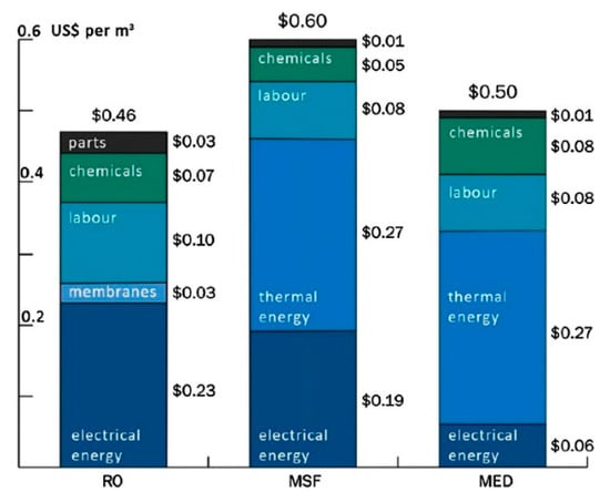
Figure 1.
The ultimate water price for each desalination technology [10].
The existence of an energy recovery system is significant; in the seawater desalination system, 40% of the seawater can permeate through the reverse osmosis membrane to get freshwater [7]. If the rest of the 60% of the high-pressure concentrated brine that cannot go through the reverse osmosis membrane is discharged directly through the pressure relief valve, then the pressure energy will be wasted.
Therefore, how to obtain freshwater resources efficiently while reducing the energy consumption of the system has become the focus of numerous research.
The energy recovery device of the seawater desalination system can be divided into two categories: the positive displacement type and centrifugal type [11]. According to the different working parts of the equipment, the positive displacement type is mainly divided into a piston type (such as DWEERTM) and a ceramic rotary type (such as PXTM). The centrifugal types are mainly divided into the Pelton turbine, hydraulic turbocharger, hydraulic pressure booster, and reverse centrifugal pump. The energy recovery devices mostly adopted the centrifugal type first in the late 20th century, to reduce the energy consumption of the high-pressure pump and recover the pressure energy at the same time. In the 21st century, positive displacement energy recovery devices began to emerge, with higher efficiency than before. At present, due to the problems with the positive displacement device, researchers have made further innovations to the centrifugal device and made various improvements to the positive displacement device [12].
The positive displacement equation is mainly applied to the recovery of residual pressure energy in large-scale integrated seawater desalination plants. Although the flow of a single device is limited, it is commonly used in combination as parallel units [13], so the unit flow rate can be adjustable and run a wide range with high recovery efficiency. However, some of the positive displacement devices have problems that the noise is loud, and equipment failures abound. The centrifugal type is mainly applied to the energy recovery of high pressure concentrated seawater in small seawater desalination equipment. Its single flow rate is larger, the operation is stable, and the operating condition can be adjusted. Meanwhile, the design, improvement, and innovation of the centrifugal type is relatively diverse [14,15].
Specific energy consumption (SEC) is a key performance index in the reverse osmosis process. It refers to the total energy consumption generated by percolating fluid per unit volume [16]. It is one of the evaluation criteria for the efficiency of energy recovery devices [17,18]. It plays a decisive role in the energy consumption of the system and is closely related to the recovery efficiency of the devices [19,20]. The application of the energy recovery unit has significantly reduced the specific energy consumption of penetration [21,22], which has promoted the development of SWRO seawater desalination [23,24].
From the perspective of reducing specific energy consumption, it is a trend to optimize the system by using optimization functions [25,26]. Each cycle of the system designed by Shayesteh [27] is composed of the power production department and the desalination water production. In order to reduce specific energy consumption and improve the recovery rate, the thermodynamic system is optimized by using the concentration disposal index (CDI) function [28]. The coordination relationship of various components in the energy recovery unit also has a great impact on the energy consumption and recovery rate [29,30]. In various energy recovery devices, the operating conditions and application conditions of various fluid machinery are different, in order to achieve the best efficiency of the system, the design, and the selection of each device crucial. Zhou et al. [31] made a comprehensive analysis of operating conditions of pump and recovery device, including motor and bypass regulating valve, so as to reach the optimal efficiency point of working together of all components, which is of great help to the selection of components of energy recovery systems under different operating conditions.
For the positive displacement energy recovery system, it is necessary to reduce the equipment floor space on the basis of high efficiency. For centrifugal types, blade optimization design and the best efficiency point (BEP) of the system will be the concern point. According to the different structures of reverse osmosis desalination systems under different operating conditions, the design principle and selection accordance of each part of the system is analyzed in this paper, to provide a theoretical and data basis for the design and selection of multiple seawater desalination energy recovery systems. The guidance of each kind of energy recovery system optimization is also provided.
2. Piston Type Energy Recovery Device
2.1. Description and Design of DWEERTM
The piston type energy recovery device (ERD) has the advantages of high efficiency, large capacity, and simple processing, and is a better choice for energy recovery in a large seawater reverse osmosis (SWRO) desalination plant [32]. A piston type ERD (such as DWEERTM) usually consists of three main components [32,33], two cylinders, a LinX valve, and a check seat (Figure 2).
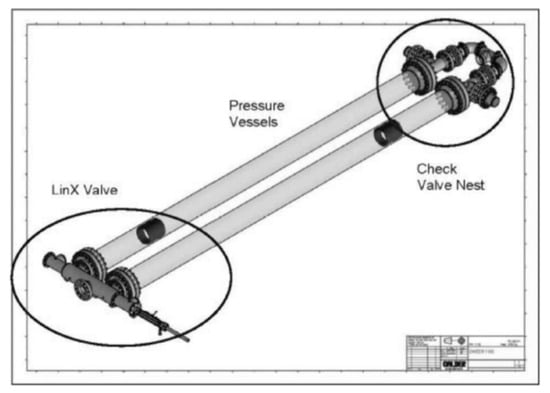
Figure 2.
The DWEERTM work exchanger [13].
The feed flow is divided into two parts, which go into the high-pressure pump and the energy recovery device, respectively. Figure 3 and Figure 4 give the scene of the recovery system. The size of the high-pressure pump is usually reduced due to the reduced flow. Booster pumps need to be installed in the system to compensate for the differential pressure on the diaphragm, and the pressure loss on the pipeline and the energy recovery unit [34]. Generally, the pump is designed for differential pressure head of approximately 30 to 40 m [13].
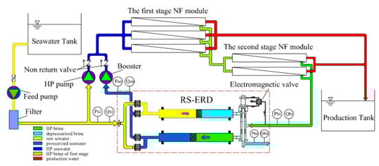
Figure 3.
The flow diagram of the RS-ERD emulated test platform [35].
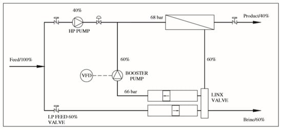
Figure 4.
Integration of the work exchanger into a RO desalination system [13].
2.2. Selection and Applications of DWEERTM
The specific energy consumption of the lines using the pressure exchanger equipment as the energy recovery system was lower than that of the lines using the Pelton turbine [36,37], and the introduction of DWEERTM reduced the total specification energy consumption by 4.82%. The unit process is shown in Figure 5. Common DWEERTM selections [13] are shown in Table 1.
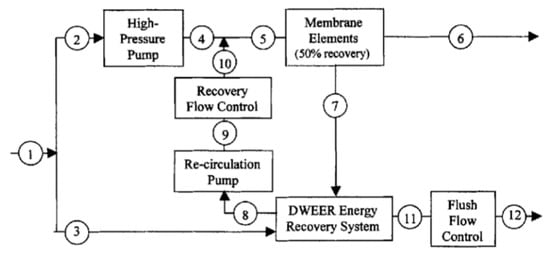
Figure 5.
SWRO unit process (DWEERTM) [38].

Table 1.
DWEERTM sizes.
At brine flows above the standard product range flow, several DWEERTMs can be grouped in a DWEERTM system, as shown in Figure 6. As Schneider [13] compared, the center design is more accepted than the train design, because the energy consumption of the center design was reduced from 2.1 to 2.01 kWh/m3. In center design, it could use three high-pressure pumps. This can run the plant at 33%, 66%, and 100% capacity, with the different quad DWEERTMs switched off.
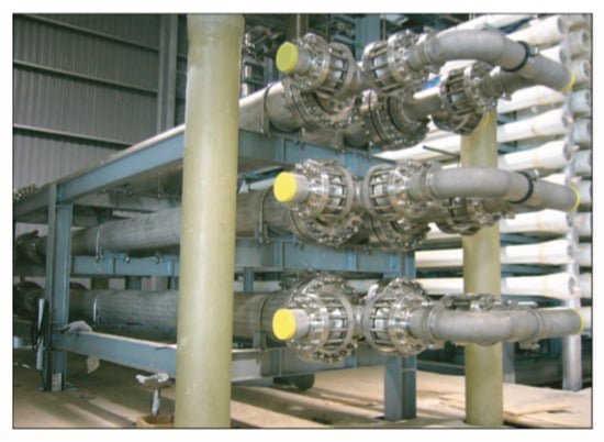
Figure 6.
Rack design of a triple DWEERTM [13].
2.3. Other Piston Type Energy Recovery Devices
Based on experimental platform research, Wang [39] developed a hydraulic control switch energy recovery device (FS-ERD), and the experimental results showed that, under the capacity of 30 m³/h and the pressure of 6.0 MPa, the efficiency of the energy recovery system was 95.9%. Song [40] experimentally studied the system adaptability of signal control and time control on the basis of FS-ERD, and developed the reciprocating switch energy recovery device (RS-ERD) with four valve plates. The experimental results showed that the efficiency of the energy recovery device was 98% under the condition of 30 m³/h and 6.5 MPa. Zhou et al. [31] mainly introduced the RS-ERD, which is a type of equal-pressure piston type ERD. It consists of three main parts: a reciprocating-switcher (RS), two hydraulic cylinders, and a passive check valve nest, as shown in Figure 7. The pressurized decompression process of low-pressure seawater and high-pressure seawater is controlled by the cooperation of a passive check seat and reciprocating-switcher (RS).
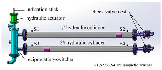
Figure 7.
The basic components of RS-ERD [31].
A single RS-ERD can run well in a capacity range of 20 m3/h to 45 m3/h, equivalent to the design 66.7% to 150.0% capacity in the stable operation. Compared to the PX products, it is the same as capacity of two PXs. Compared to the DWEERTM, the control mode of DWEERTM limits the flexibility of capacity [13].
There are two main factors affecting RS-ERD efficiency; one is the leakage rate; the other is the pressure loss in the fluid. Equation (1) is a general formula for calculating the energy recovery efficiency of ERD [31]. As shown in Figure 8, when the flow is less than 30 m³/h, leakage is the dominant factor affecting the efficiency. When the flow exceeds the designed capacity of more than 30 m³/h, the pressure loss will become the main factor, and the influence will be more obvious than leakage.
where Psi means the pressure of the feed seawater inlet, MPa. Pso means the pressure of the pressurized seawater outlet, MPa. Pbi means the pressure of high-pressure brine inlet, MPa. Pbo means the pressure of the depressurized brine outlet, MPa. Qsi means the flow rate of the feed seawater inlet, m³/h. Qso means flowrate of the pressurized seawater outlet, m³/h. Qbi means flow rate of high-pressure brine inlet, m³/h. Qbo means flowrate of the depressurized brine outlet, m³/h.
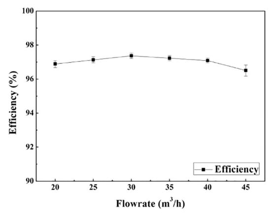
Figure 8.
The energy recovery efficiency in different capacities [31].
As for the piston type isobaric ERD, because of the vibration and other problems, it requires regular maintenance of the piston and valves [41].
3. Pressure Exchanger
3.1. Description and Design of Pressure Exchanger
The Pressure Exchanger (PX) is a typical rotary energy recovery device [42,43] that consists of three main parts: a rotating rotor for pressure exchange, a sleeve, and two end caps [44].
The working process of PX is shown in Figure 9. The liquid transmits pressure through a short period of direct contact, and the PX rotor is used to transfer the pressure from the high-pressure brine discharge to the low-pressure seawater feed stream. Transfer occurs in the rotor pipe. The rotor is mounted in a ceramic sleeve between two ceramic end covers and has a precise clearance to form a fluid sliding bearing [45,46]; high-pressure and water-filled.
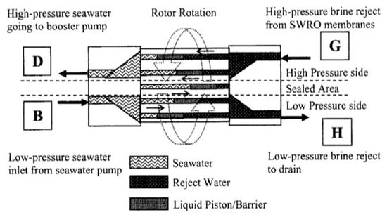
Figure 9.
PX flow schematic [45].
When the rotor rotates, the high-pressure area and the low-pressure area will form the sealing area respectively through the pipe. If the high-pressure flow is equal to the low-pressure flow, Equation (2) is used to calculate the mix proportion of flow [47].
where HP means high-pressure water, LP means low-pressure water.
PX, the direct positive displacement, makes the net transfer efficiency up to 97%, and has the behefits of a low failure rate, being not easy to corrode, and a low vibration. The relationship between system capacity (capital and operating costs) and the recovery rate is shown in Figure 10.
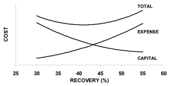
Figure 10.
The overall plant cost optimization diagram [42].
The PX energy device does not require regular maintenance [42], and if the PX rotor stops rotating for any reason, the water will flow unimpeded through the path of equipment, because there are no pistons or obstacles in the flow path through the equipment, and the damage of one of the rotors has little impact on the SWRO membrane [31,48]. This gives the equipment and maintenance staff time to buffer.
3.2. Selection and Applications of PXTM Units
PX was produced in 1989 [49,50] and first introduced as a commercial product in 1997 [51]. The processing capacity of a single rotor was increased to 50 m³/h after several generations of design improvement. The PX unit produces an almost perfect hydraulic disconnect between the high pressure and low-pressure pipelines [52,53,54]. The PX rotor rotates 500 to 2000 rotations per minute and is divided into 12 tubes with two sides. It can withstand pressures ranging from 12,000 to 48,000 per minute [45]. Multi-PX arrays are usually applied in large scale desalination plants, as Figure 11 displays the PX-120 array.
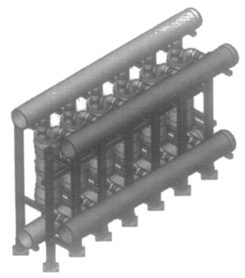
Figure 11.
Twelve PX-120 arrays [45].
The fourth-generation device was the big rotor PX-200 [55]. The size is larger, with the water hammer and cavitation phenomenon is more serious, but this can be solved by the gentle transition of pressure. The efficiency decrease caused by fluid mixing in the PX-220 is approximately 1% at balanced flow, the same as the operating pressure to increase by approximately 1.3 bar. The efficiency of PX in the greater rotor is about 95%. The largest PX, PX-220 [45], has a capacity of 220 GPM or 50 m³/h, which can be integrated and run in parallel to achieve unlimited capacity. For example, a 10,000 m³/d SWRO plant running at a 45% recovery rate would require about 10 PX-220 units.
The basic information of PX device selection is exhibited in Table 2 Manipulating PX outside the capacity range may cause the rotor to rotate unsteadily in the sleeve [52].
Table 2.
The PX sizes available [31,45].
Ashkelon seawater reverse osmosis plan [53] was the largest single-train SWRO capacity in 2007, whose full capacity of drinking water was 330,000 m3/d. It adopted a pressure center design. The Hamma (Algeria) desalination plant, designed by General Electric, Water Section, was the second largest plant at that time, was introduced by Mambrettia et al. [52] The plant adopted the train design method, utilized one array of 32 PX-220 devices on each of the nine first-pass trains for a total of 288 PX units, to minimize the high costs of processing the expected 200,000 m3/d of water [54]. The Hamma plant operates at 1084 m3/h and the efficiency is about 88%; the booster pump operates at 1351 m3/h and the efficiency is about 89% [52].
4. Pelton Turbine
4.1. Description and Design of Pelton Turbine
Although volumetric devices like DWEERTM and PX do have some interesting potential, centrifugal devices are the most widely used energy recovery technology by far and cut a figure in desalination field in uptime, flexibility, mechanical simplicity and robustness [56]. More than 98% of reverse-osmosis equipment installed worldwide has chosen centrifugal devices [41].
In centrifugal energy recovery devices, the Pelton turbine is a common counterattack turbine, widely used in seawater desalination energy recovery systems. The efficiency of the Pelton turbine at 570m³/h and 3000 rpm is shown in Figure 12.
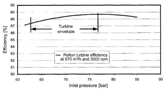
Figure 12.
Pelton turbine efficiency curve [41].
According to the turbomachinery affinity law that the Pelton turbine follows, when rotating speed accelerates, the power input approximately grows cubically as a function of the speed. And the relation between efficiency and input power is described in Equation (3) [57]. With the affinity laws applied, the efficiency curve can be normalized when the operating speed changed [58].
where η means efficiency, N means input power.
The turbine part of the energy recovery device is coaxially connected with the high-pressure pump. The pump and turbine systems can find the same operating point by intelligent design of key parts of structure or system [14,15], such as the bucket of the turbine and impeller diameter [59,60,61]. The whole turbine structure and blade structure are shown in Figure 13 and Figure 14.
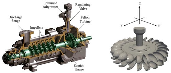
Figure 13.
ERD assembled on the high-pressure centrifugal pump (left) [29] and the geometry of the runner (right) [14].
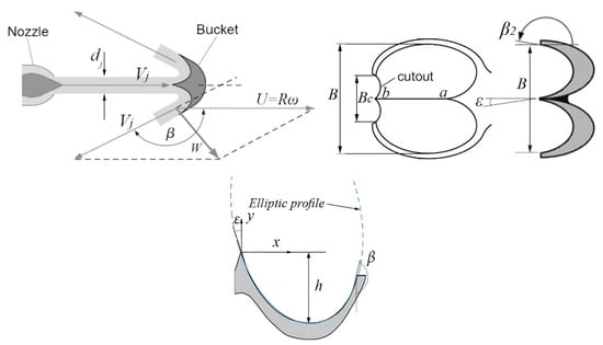
Figure 14.
Bucket design for a Pelton turbine blade [29].
The design of the turbine bucket dimension is one of the key points to blades optimization [62,63]. The detailed parameters of condition that regulate the valve calculation for full opening are listed in Table 3.
Table 3.
Regulating valve calculation for the full opening condition [29].
4.2. Selection and Application of Pelton Turbine
Manth et al. [41,64] argued that the key point to minimize the specific energy consumption (SEC) is to control the plant as a whole system and reduce throttling losses. By choosing a ring section pump, the energetic efficiency could come to 85% at the considered flow rate with the nominal speed of 3000 rpm. This pump is supplied by Duechting Pulnpen GmbH of Witten, Germany. The two-stages reverse osmosis desalination process is exhibited in Figure 15.
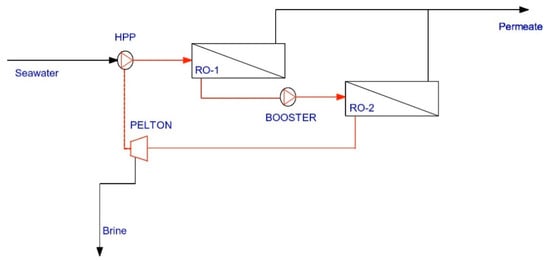
Figure 15.
Schematic of a line with a Pelton turbine [64].
Based on the principle of specific energy consumption, the impact of throttling in the system is analyzed as follows in Table 4 [41,65].
Table 4.
Two types of flowrate controlling.
The first pump is used to provide the basic energy required for PROP in the system [66,67]. The duty point, which is the best efficiency point (BEP) of the reverse osmosis package, ensures efficient progress and stable energy input [41]. Sani [29] believes that impeller geometry and operating synchronicity of the turbine between turbine speed and centrifugal pump speed are important for improving efficiency and recovering the input power of energy recovery devices. The main parts and the seawater distribution of RO package introduced by Sani are shown in Figure 16.
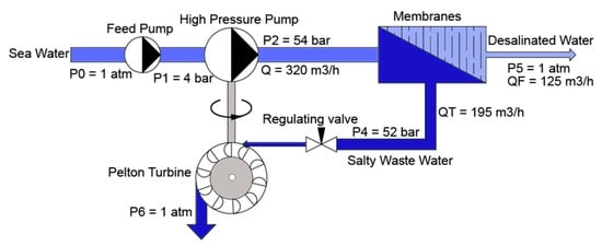
Figure 16.
Schematic diagram of the cycle performance package [29].
Nowadays, in order to make energy recovery of reverse osmosis desalination process towards the direction of efficiency, the better match between high-pressure pumps, transmembrane pressures, and permeable fluids is often found by using equations and genetic algorithms [65,68].
5. Hydraulic Turbocharger and Hydraulic Pressure Booster
5.1. Description of Hydraulic Turbocharger and Hydraulic Pressure Booster
The hydraulic turbocharger (HTC), designed and manufactured by Pump Engineering Inc. [69], consists of two parts: a turbine and a pump whose blades are mounted on the same shaft. High-pressure brine enters into the turbine parts by a nozzle, with a bypass to adjust and control the flow and pressure of brine [70,71]. A hydraulic pressure booster (HPB), produced by FEDCO companies in the United States [72], is the second generation of energy recovery device on the basis of HTC. In this device, the saltwater control valve and energy recovery device are combined as a complete part instead of the bypass regulation. Both of those two kinds of devices work under the condition of a large flow rate [73]. The residual pressure energy of recovered brine is used to further pressurize seawater to the demanded pressure, which is equivalent to the role of booster pump in the process [74]. The energy recovery unit runs in series with a high-pressure pump to decrease system energy consumption by reducing the outlet pressure of the high-pressure pump.
With the hydraulic turbocharger (HTC), its overall energy transfer efficiency was up to 71%, applied for a reject flow ratio (i.e., the brine flow rate through the hydraulic turbo-booster/feed flow rate) of 60% [75].
Compared with other centrifugal energy recovery devices, the miniaturization of motors and switches, as well as the elimination of brine pressure relief valves, can save additional costs in new systems designed specifically for energy recovery. Systems such as ROWPU can save about $2000 [76]. The equipment itself has the advantages of low cost, small floor space, and low energy consumption. By reducing the discharge pressure of the feed pump, the life of the feed pump components such as packing, valves, crossheads, and crank bearings is extended, resulting in additional cost savings [77,78].
5.2. Design and Selection of Energy Recovery Integration
The Fluid Machinery Team of Zhejiang University keeps the opinion that the efficiency of the integrated system composed of each recovery part cannot be represented by the efficiency of a single device, and the speed coordination of the primary pump, secondary pump, and turbine is more important. The energy recovery device (Figure 17) studied by Tamer et al. [30] is composed of the direct connection of the turbine, hydraulic turbocharger, and motor, which is called hydraulic energy management integration (HEMI). The study showed that where the auxiliary pipe size and valve opening were larger, the turbine inlet pressure was lower. The increase in turbine inlet pressure will lead to an increase of turbine rotating speed. In the device system set in this condition, the turbine efficiency is highest when the speed is 11,000 rpm, and the balance between the pump and turbine will be realized at about 10,000 rpm.
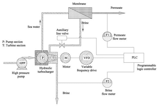
Figure 17.
The control scheme of the HEMI system [30].
In 1992, Silbernagel et al. tested the high-pressure system. The size of the energy recovery device is shown in the Table 5 [76].
Table 5.
Size of the energy recovery device.
According to the test results, in the device displaced in Figure 18, the new rotor was made of a 2205 duplex alloy [79] and contained nitrogen, so the maximum strength of the shaft was achieved; The chrome oxide coating was used instead of alumina [76]. For the integrated RO package, more improvement has been made: the thrust bearing that can transmit more power adopted [80]; increase the shell thickness by increasing the flange; the shaft was placed in tension by rotor thrust to maximizing wear ring life [8].
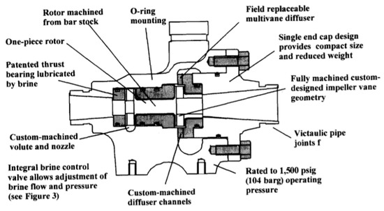
Figure 18.
The internal construction and features of the HPBTM [8].
In terms of salinity and temperature, the design data can be considered to be representative of the Arabian gulf sea conditions [41]. The hydraulic assumptions of the case study plant are summarized in Table 6.
Table 6.
Hydraulic assumptions for model calculations [41].
The heart part of the integrated RO package (IROP) or hydraulic energy management integration (HEMI) is the feed pump and the energy recovery device [81]. The feed pump could select from Designated the TONKAFLO® SW series. The rated operating speed is 4200 rpm offered by TEFC motor, which is driven by VFD, the output frequency of the motor is 70 Hz [8]. HPB™ is turbocharged with high-pressure brine, which drives the single-stage booster pump [82]. The feed pressure lift generated by HPB™ reduces the required discharge pressure of the feed pump, thereby saving energy and reducing the size of the feed pump and motor [83].
The IROP assembly excluding the VFD can pump feed at up to 20 m3/h (85 gpm) at 67 bar (950 psig). The unit is driven by a 37 kW (50 hp) TEFC motor. The IROP standardized by the VFD is widely used, capable of operating at 50 or 60 Hz electric power with the same efficiency. ERT control valves and cleaning pump kits integrate components to simplify high-pressure pipes. One package can handle feed flows from about 50 gpm (12 m3/h) to 200 gpm (45 m3/h) [84]. The system is equipped with a control function to control the flow rate of the permeable fluid and brine [85,86].
The system components are shown in Figure 19. System parameters [8] of 120 m3/d and 500 m3/d output plant are listed in Table 7 and Table 8 below.
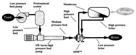
Figure 19.
Component arrangement in a typical SWRO system [8].
Table 7.
A 120 ton/d example [8].
Table 8.
A 150 ton/d example [8].
6. Discussion and Conclusions
The positive displacement type and centrifugal type are two kinds of energy recovery devices. The classification, current status, and growing trend of different devices are discussed in Table 9.
Table 9.
Comparison and conclusion of energy recovery devices.
The positive displacement energy recovery device generally recycles the energy of high-pressure concentrated seawater through the direct transfer of liquid pressure. Therefore, its operation mechanism is simple, the device is efficient, and the usage is large in the early 21st century. In recent years, people have carried out blade design and pipeline improvement optimization for centrifugal energy recovery devices and found that the synchronism of devices is the key point to the energy recovery system. According to this point, researchers designed an integrated system with an energy recovery device as the core and other equipment as the auxiliary, so as to improve the overall system efficiency and energy consumption formed by the device and pipeline.
Different energy recovery devices are applied to different operating conditions. At present, the design and development of the energy recovery device of the seawater desalination system is relatively mature. It is becoming a top trend for people to study whether device selection or design conforms to the operating conditions of the system and whether it can simultaneously reach the optimal operating conditions of all devices in the system.
Author Contributions
Conceptualization, B.H. and K.P.; methodology, P.W. and D.W.; validation, B.H. and J.L.; formal analysis, K.P. and P.W.; investigation, B.H. and K.P.; resources, P.W., D.W. and J.L.; data curation, B.H. and K.P.; writing—original draft preparation, K.P.; writing—review and editing, B.H. and K.P.; visualization, P.W.; supervision, D.W. and J.L.; project administration, B.H. and D.W.; funding acquisition, B.H. All authors have read and agreed to the published version of the manuscript.
Funding
This research was funded by National Natural Science Foundation of China, grant number 51706198 and 51839010.
Acknowledgments
The computational resource was supported by HPC Center of ZJU (ZHOUSHAN CAMPUS).
Conflicts of Interest
The authors declare no conflict of interest.
References
- Shufei, Z.; Libo, X.; Zidan, X. Analysis on the development history and current situation of seawater desalination at home and abroad. Water Treat. Technol. 2014, 40, 12–15, 23. [Google Scholar]
- Van der Bruggen, B. Desalination by distillation and by reverse osmosis—Trends towards the future. Membr. Technol. 2003, 2, 6–9. [Google Scholar]
- El-Dessouky, H.; Ettouney, H. MSF developments may reduce desalination costs. Water Wastewater Int. 2000, 15, 20–21. [Google Scholar]
- Barragán, V.M.; Bauzá, C.R.; Imaña, J.L. Effect of an AC perturbation on a desalination electrodialysis process. Desalination 2002, 142, 235–244. [Google Scholar]
- Hanshik, C.; Jeong, H.; Jeong, K.-W.; Choi, S.-H. Improved productivity of the MSF (multi-stage flashing) desalination plant by increasing the TBT (top brine temperature). Energy 2016, 107, 683–692. [Google Scholar]
- Kim, J.; Park, K.; Yang, D.R.; Hong, S. A comprehensive review of energy consumption of seawater reverse osmosis desalination plants. Appl. Energy 2019, 254, 113652. [Google Scholar] [CrossRef]
- Yanyue, L. Research on Optimal Design of Reverse Osmosis Seawater Desalination System. Ph.D. Thesis, Ocean University of China, Qingdao, China, 2004. [Google Scholar]
- Oklejas, E.; Pergande, W.F. Integration of advanced high-pressure pumps and energy recovery equipment yields reduced capital and operating costs of seawater RO systems. Desalination 2000, 127, 181–188. [Google Scholar] [CrossRef]
- Tianbao, S.; Lu, L.; Jianwei, B.; Xidong, X.; Yulian, Y.; Chunyou, P. Key points of design and equipment selection of reverse osmosis seawater desalination high-pressure system. Water Purif. Technol. 2019, 38, 131–134. [Google Scholar]
- Escobar, I.C.; Schäfer, A.I. Sustainable Water for the Future Water Recycling Versus Desalination; Academic Press, Elsevier: Cambridge, MA, USA, 2010. [Google Scholar]
- Wilf, M.; Bartels, C. Optimization of seawater RO systems design. Desalination 2005, 173, 1–12. [Google Scholar] [CrossRef]
- Okamoto, Y.; Lienhard, J.H. How RO membrane permeability and other performance factors affect process cost and energy use: A review. Desalination 2019, 470, 114064. [Google Scholar] [CrossRef]
- Schneider, B. Selection, operation and control of a work exchanger energy recovery system based on the Singapore project. Desalination 2005, 184, 197–210. [Google Scholar] [CrossRef]
- Alimirzazadeh, S.; Kumashiro, T.; Leguizamón, S.; Jahanbakhsh, E.; Maertens, A.; Vessaz, C.; Tani, K.; Avellan, F. GPU-Accelerated numerical analysis of jet interference in a six-jet Pelton turbine using Finite Volume Particle Method. Renew. Energy 2020, 148, 234–246. [Google Scholar] [CrossRef]
- Suyesh, B.; Parag, V.; Keshav, D.; Ahmed, A.M.; Abdul-Ghani, O. Novel trends in modelling techniques of Energy efficiency considerations Pelton Turbine bucket for increased renewable energy production. Renew. Sustain. Energy Rev. 2019, 112, 87–101. [Google Scholar]
- Avlonitis, S.A.; Kouroumbas, K.; Vlachakis, N. Energy consumption and membrane replacement cost for seawater RO desalination plants. Desalination 2003, 157, 151–158. [Google Scholar] [CrossRef]
- Oklejas, E.; Manth, T. Energy efficiency considerations for RO plants: A comparative study. In Proceedings of the IDA World Congress on Desalination and Water Reuse, Manama, Bahrain, 8–13 March 2002. [Google Scholar]
- Li, M. Reducing specific energy consumption in Reverse Osmosis (RO) water desalination: An analysis from first principles. Desalination 2011, 276, 128–135. [Google Scholar] [CrossRef]
- Zhu, A.; Christofides, P.D.; Cohen, Y. Effect of thermodynamic restriction on energy cost optimization of RO membrane water desalination. Ind. Eng. Chem. Res. 2008, 48, 6010–6021. [Google Scholar] [CrossRef]
- Zhu, A.; Christofides, P.D.; Cohen, Y. Energy consumption optimization of reverse osmosis membrane water desalination subject to feed salinity fluctuation. Ind. Eng. Chem. Res. 2009, 48, 9581–9589. [Google Scholar]
- Zhu, A.; Christofides, P.D.; Cohen, Y. On RO membrane and energy costs and associated incentives for future enhancements of membrane permeability. J. Membr. Sci. 2009, 344, 1–5. [Google Scholar] [CrossRef]
- Gordon, J.M.; Hui, T.C. Thermodynamic perspective for the specific energy consumption of seawater desalination. Desalination 2016, 386, 13–18. [Google Scholar] [CrossRef]
- Shannon, M.A.; Bohn, P.W.; Elimelech, M.; Georgiadis, J.G.; Marinas, B.J.; Mayes, A.M. Science and technology for water purification in the coming decades. Nature 2008, 452, 301–310. [Google Scholar] [CrossRef]
- Koutsou, C.P.; Kritikos, E.; Karabelas, A.J.; Kostoglou, M. Analysis of temperature effects on the specific energy consumption in reverse osmosis desalination processes. Desalination 2020, 476, 114213. [Google Scholar] [CrossRef]
- Abbas, A.; Al-Bastaki, N.M. Modeling of an RO water desalination unit using neural networks. Chem. Eng. J. 2005, 114, 139–143. [Google Scholar] [CrossRef]
- Busch, M.; Mickols, W.E. Reducing energy consumption in seawater desalination. Desalination 2004, 165, 299–312. [Google Scholar] [CrossRef]
- Hu, Y.D.; Lu, Y.Y. Cleaning strategy of the membrane modules in the reverse osmosis seawater desalination system. J. Chem. Ind. Eng. 2005, 56, 499–505. [Google Scholar]
- Shayesteh, A.A.; Koohshekan, O.; Ghasemi, A.; Nemati, M.; Mokhtari, H. Determination of the ORC-RO system optimum parameters based on 4E analysis. Water Energy Environ. Nexus Energy Convers. Manag. 2019, 183, 772–790. [Google Scholar]
- Sani, A.E. Design and synchronizing of Pelton turbine with centrifugal pump in RO package. Energy 2019, 172, 787–793. [Google Scholar] [CrossRef]
- El-Sayed, T.A.; Abdel Fatah, A.A. Performance of hydraulic turbocharger integrated with hydraulic energy management in SWRO desalination plants. Desalination 2016, 379, 85–92. [Google Scholar]
- Zhou, J.; Wang, Y.; Duan, Y.; Tian, J.; Xu, S. Capacity flexibility evaluation of a reciprocating-switcher energy recovery device for SWRO desalination system. Desalination 2017, 416, 45–53. [Google Scholar]
- Shumway, A.S. The work exchanger for SWRO energy recovery. Int. Desalin. Water Reuse Q. 1999, 8, 27–31. [Google Scholar]
- Shumway, S. Linear Spool Valve Device for Work Exchanger System. U.S. Patent 5797429, 25 August 1998. [Google Scholar]
- Urrea, S.A.; Reyes, F.D.; Suárez, B.P.; de la Fuente Bencomo Juan, A. Technical review, evaluation and efficiency of energy recovery devices installed in the Canary Islands desalination plants. Desalination 2019, 450, 54–63. [Google Scholar] [CrossRef]
- Song, D.; Wang, Y.; Xu, S.; Gao, J.; Ren, Y.; Wang, S. Analysis, experiment and application of a power-saving actuator applied in the piston type energy recovery device. Desalination 2015, 361, 65–71. [Google Scholar] [CrossRef]
- Jamil, F.; Ali, H.M. Sustainable desalination using portable devices: A concise review. Solar Energy 2019, 194, 815–839. [Google Scholar] [CrossRef]
- Sun, J.; Wang, Y.; Xu, S.; Wang, S.; Wang, Y. Performance prediction of hydraulic energy recovery (HER) device with novel mechanics for small-scale SWRO desalination system. Desalination 2009, 249, 667–671. [Google Scholar] [CrossRef]
- Andrews, W.T.; Pergande, W.F.; McTaggart, G.S. Energy performance enhancements of a 950 m³/d seawater reverse osmosis unit in Grand Cayman. Desalination 2001, 135, 195–204. [Google Scholar] [CrossRef]
- Wang, Z.C.; Wang, Y.; Zhang, Y.P.; Qi, B.W.; Xu, S.C.; Wang, S.C. Pilot tests of fluid-switcher energy recovery device for seawater reverse osmosis desalination system. Desalin. Water Treat. 2012, 48, 310–314. [Google Scholar] [CrossRef]
- Song, D.W.; Wang, Y.; Lu, N.Y.; Liu, H.; Xu, E.L.; Xu, S.C. Development and stand tests of reciprocating-switcher energy recovery device for SWRO desalination system. Desalin. Water Treat. 2015, 54, 1519–1525. [Google Scholar]
- Manth, T.; Gabor, M.; Oklejas, E. Minimizing RO energy consumption under variable conditions of operation. Desalination 2003, 157, 9–21. [Google Scholar]
- Stover, R.L. Seawater reverse osmosis with isobaric energy recovery devices. Desalination 2007, 203, 168–175. [Google Scholar] [CrossRef]
- Ayati, E.; Rahimi-Ahar, Z.; Hatamipour, M.S.; Ghalavand, Y. Water productivity enhancement in variable pressure humidification dehumidification (HDH) desalination systems using heat pump. Appl. Therm. Eng. 2019, 160, 114114. [Google Scholar] [CrossRef]
- Andrews, W.T.; Laker, D.S. A twelve-year history of large scale application of work exchanger energy recovery technology. Desalination 2001, 138, 201–206. [Google Scholar]
- Stover, R.L. Development of a fourth generation energy recovery device. A ‘CTO’s Notebook’. Desalination 2004, 165, 313–321. [Google Scholar] [CrossRef]
- Cameron, I.B.; Clemente, R.B. SWRO with ERI’s PX pressure exchanger device—A global survey. Desalination 2008, 221, 136–142. [Google Scholar] [CrossRef]
- MacHarg, J.P. Retro-Fitting exiting SWRO systems with a new energy recovery device. Desalination 2002, 153, 253–264. [Google Scholar] [CrossRef]
- Elimelech, M.; Phillip, W.A. The future of seawater desalination: Energy, technology, and the environment. Science 2016, 333, 712–717. [Google Scholar]
- Shumway, S. Pressure Exchanger Apparatus. U.S. Patent 6537035 B2, 25 March 2003. [Google Scholar]
- Hauge, L.J. Pressure Exchanger for Liquids. U.S. Patent 4887942, 19 December 1989. [Google Scholar]
- Hauge, L.J. The Pressure Exchanger. Desalin. Water Reuse 1999, 9, 54–60. [Google Scholar]
- Mambretti, S.; Orsi, E.; Gagliardi, S.; Stover, R. Behaviour of energy recovery devices in unsteady flow conditions and application in the modelling of the Hamma desalination plant. Desalination 2009, 238, 233–245. [Google Scholar] [CrossRef]
- Sauvet-Goichon, B. Ashkelon desalination plant—A successful challenge. Desalination 2007, 203, 75–81. [Google Scholar] [CrossRef]
- Stover, R.L.; Ameglio, A.; Khan, P.A.K. The Ghalilah SWRO plant: An overview of the solutions adopted to minimize energy consumption. Desalination 2005, 184, 217–221. [Google Scholar] [CrossRef]
- Zheng, H.; Chang, Z.; Chen, Z.; Xie, G.; Wang, H. Experimental investigation and performance analysis on a group of multi-effect tubular solar desalination devices. Desalination 2013, 311, 62–68. [Google Scholar] [CrossRef]
- Woodcock, D.J.; White, M.I. The application of Pelton type impulse turbines for energy recovery on sea water reverse osmosis systems. Desalination 1981, 39, 447–458. [Google Scholar] [CrossRef]
- Karassik, I.; McGuire, J.T. Centrifugal Pumps; Springer: Berlin/Heidelberg, Germany, 1998. [Google Scholar]
- Zhang, Z.H. Pelton Turbines; Springer: Berlin/Heidelberg, Germany, 2009. [Google Scholar]
- Kvicinsky, S.; Kueny, J.; Avellan, F.; Parkinson, E. Experimental and numerical analysis of free surface flows in a rotating bucket. In Proceedings of the 21st IAHR symposium on hydraulic machinery and systems, Lausanne, Switzerland, 21–26 March 2002. [Google Scholar]
- Perrig, A.; Avellan, F.; Kueny, J.; Farhat, M.; Parkinson, E. Flow in a Pelton turbine bucket: Numerical and experimental investigations. J. Fluid Eng. Trans. ASME 2006, 128, 350–358. [Google Scholar] [CrossRef]
- Zoppê, B.; Pellone, C.; Maitre, T.; Leroy, P. Flow analysis inside a Pelton turbine bucket. J. Turbomach. Trans. ASME 2006, 128, 500–511. [Google Scholar] [CrossRef]
- Parkinson, E.; Neury, C.; Garcin, H.; Weiss, T. Unsteady Analysis of a Pelton Runner, with Flow and Mechanical Simulations; Hydro: Villach, Austria, 2005. [Google Scholar]
- Angehrn, R. Safety engineering for the 423 MW-Pelton-runners at Bieudron. In Proceedings of the 20th IAHR Symposium, Charlotte, NC, USA, 6–9 August 2000. [Google Scholar]
- Blanco-Marigorta, A.M.; Lozano-Medina, A.; Marcos, J.D. The exergetic efficiency as a performance evaluation tool in reverse osmosis desalination plants in operation. Desalination 2017, 413, 19–28. [Google Scholar] [CrossRef]
- Lee, S.; Myung, S.; Hong, J.; Har, D. Reverse osmosis desalination process optimized for maximum permeate production with renewable energy. Desalination 2016, 398, 133–143. [Google Scholar] [CrossRef]
- Gülich, J.F. Centrifugal Pumps, 2nd ed.; Springer: Berlin/Heidelberg, Germany; London, UK, 2010. [Google Scholar]
- Shojaeefard, M.H.; Tahani, M.; Ehghaghi, M.B.; Fallahian, M.A.; Beglari, M. Numerical study of the effects of some geometric characteristics of a centrifugal pump impeller that pumps a viscous fluid. Comput. Fluids 2012, 60, 61–70. [Google Scholar] [CrossRef]
- Greenlee, L.F.; Lawler, D.F.; Freeman, B.D.; Marrot, B.; Moulin, P. Reverse osmosis desalination: Water sources, technology, and today’s challenges. Water Res. 2009, 43, 2317–2348. [Google Scholar]
- Oklejas, E., Jr. Hydraulic Energy Recovery Device. U.S. Patent WO2000043657A3, 5 May 2002. [Google Scholar]
- Lozier, J.; Oklejas, E.; Silbernagel, M. The hydraulic turbocharger (TM): A new type of device for the reduction of feed pump energy consumption in reverse osmosis systems. Desalination 1989, 75, 71–83. [Google Scholar] [CrossRef]
- Uchiyama, T.; Oklejas, M.; Moch, I. Using a Hydraulic TurboCharger and Pelton Wheel for Energy Recovery in the Same Seawater RO Plant; San Diego Proceeding, San Diego; International Desalination Association: Topsfield, MA, USA, 1999. [Google Scholar]
- Kim, S.-H.; Kim, G.-T.; Yim, S.-K. Application of energy efficient reverse osmosis system for seawater desalination. Desalination 2002, 144, 361–365. [Google Scholar] [CrossRef]
- Walsham, B.E. Alternative turbocharger systems for the automotive diesel engine. In Proceedings of the 4th International Conference Turbocharging Turbochargers, London, UK, 22–24 May 1990; IMechE: London, UK, 1990. [Google Scholar]
- Feneley, A.J.; Pesiridis, A.; Andwari, A.M. Variable geometry turbocharger technologies for exhaust energy recovery and boosting—A review. Renew. Sustain. Energy Rev. 2017, 71, 959–975. [Google Scholar] [CrossRef]
- Pump Engineering, Inc. Apparatus for Improving Efficiency of a Reverse Osmosis System. U.S. Patent 6139740, 31 October 2000. [Google Scholar]
- Silbernagel, M.; Kuepper, T.; Oklejas, E. Evaluation of a pressure boosting pump/turbine device for reverse osmosis energy recovery: Extended testing on a seawater desalination system. Desalination 1992, 88, 311–319. [Google Scholar] [CrossRef]
- Diaz, C.; Ruiz, F.; Patino, D. Modeling and control of water booster pressure systems as flexible loads for demand response. Appl. Energy 2017, 204, 106–116. [Google Scholar] [CrossRef]
- Guirguis, M.J. Energy Recovery Devices in Seawater Reverse Osmosis Desalination Plants with Emphasis on Efficiency and Economical Analysis of Isobaric Versus Centrifugal Devices. Ph.D. Thesis, University of South Florida, Tampa, FL, USA, 2011. [Google Scholar]
- Oklejas, E., Jr. Hydraulic TurboChargerTM for interstage feed pressure boosting. Impact on membrane performance, permeate quality, and feed pump energy consumption. Desalination 1992, 88, 289–300. [Google Scholar] [CrossRef]
- Plaksin, A.; Gritsenko, A.; Glemba, K. Modernization of the Turbocharger lubrication system of an internal combustion engine. Procedia Eng. 2015, 129, 857–862. [Google Scholar] [CrossRef][Green Version]
- Oklejas, E., Jr.; Leachman, L.M.; Kitzmiller, R.T.; Seisan, A.; Kadaj, E. A novel equipment centralization schema reduces the cost of permeate. In Proceedings of the International Desalination Association World Congress, Maspalomas de Gran Canaria, Spain, 21–26 October 2007. [Google Scholar]
- Li, X.; Chen, B.; Luo, X.; Zhu, Z. Effects of flow pattern on hydraulic performance and energy conversion characterisation in a centrifugal pump. Renew. Energy 2020, 151, 475–487. [Google Scholar] [CrossRef]
- Li, D.; Zuo, Z.; Wang, H.; Liu, S.; Wei, X.; Qin, D. Review of positive slopes on pump performance characteristics of pump-turbines. Renew. Sustain. Energy Rev. 2019, 112, 901–916. [Google Scholar] [CrossRef]
- Oklejas, E.J. Hunt, Integrated pressure and flow control in SWRO with a HEMI turbobooster. Desalin. Water Treat. 2011, 31, 88–94. [Google Scholar] [CrossRef][Green Version]
- Oklejas, E., Jr. Control Scheme for a Reverse Osmosis System Using a Hydraulic Energy Management Integration System; Fluid Equipment Development Company, LLC: Monroe, MI, USA, 2010. [Google Scholar]
- Escajadillo, V.R. Impact and Sensitivity of Diverse Parameters Over the Cost Structure of Reverse Osmosis Systems. Civil Engineering. Master’s Thesis, Delft University of Technology, Delft, The Netherlands, 2016. [Google Scholar]
© 2020 by the authors. Licensee MDPI, Basel, Switzerland. This article is an open access article distributed under the terms and conditions of the Creative Commons Attribution (CC BY) license (http://creativecommons.org/licenses/by/4.0/).