Article

Advanced Variable Step Size Incremental Conductance MPPT for a Standalone PV System Utilizing a GA-Tuned PID Controller

1
Department of Automation, University of Science and Technology of China, Hefei 230027, China
2
Hefei National Lab for Physical Sciences at the Microscale and the Centers for Biomedical Engineering, University of Science and Technology of China, Hefei 230027, China
3
Department of Physics and Astronomy, College of Science, King Saud University, PO Box 2455, Riyadh 11451, Saudi Arabia
*
Authors to whom correspondence should be addressed.
Energies 2020, 13(16), 4153; https://doi.org/10.3390/en13164153
Submission received: 13 July 2020 / Revised: 5 August 2020 / Accepted: 6 August 2020 / Published: 11 August 2020
(This article belongs to the Section A2: Solar Energy and Photovoltaic Systems)

Abstract

:
In this article, a novel maximum power point tracking (MPPT) controller for the fast-changing irradiance of photovoltaic (PV) systems is introduced. Our technique utilizes a modified incremental conductance (IC) algorithm for the efficient and fast tracking of MPP. The proposed system has a simple implementation, fast tracking, and achieved steady-state oscillation. Traditional MPPT techniques use a tradeoff between steady-state and transition-state parameters. The shortfalls of various techniques are studied. A comprehensive comparative study is done to test various existing techniques against the proposed technique. The common parameters discussed in this study are fast convergence, efficiency, and reduced oscillations. The proposed method successfully addresses these issues and improves the results significantly by using a proportional integral deferential (PID) controller with a genetic algorithm (GA) to predict the variable step size of the IC-based MPPT technique. The system is designed and tested against the perturbation and observation (P&O)-based MPPT technique. Our technique effectively detects global maxima (GM) for fast-changing irradiance due to the adopted GA-based tuning of the controller. A comparative analysis of the results proves the superior performance and capabilities to track GM in fewer iterations.

1. Introduction

Nonrenewable fossil fuel-based energy has been the driving force of economies, recent advancements in technology, the availability of resources, global warming, and changing economic models and the depletion of conventional resources [1] has pushed governments and researchers to come up with novel ideas to address all the issues in single solution [2]. Renewable resources are nowadays a significant addition to the ever-increasing demand for energy [3]. Biogas, wind, solar, and wave energy are emerging at a fast pace and, among these, solar stands out due to its high efficiency, low maintenance cost, and scalability. Renewable energy is the need of the hour. Solar energy is expected to provide 1/3 of the world’s electrical energy demands by the year 2060. All other forms of renewable energy resources are highly restricted to geographical availability. Wind, geothermal, and tidal wave energy are highly localized. The only form abundant enough throughout the globe is solar energy. Rapidly falling manufacturing prices, technological improvement, favorable governmental legislation, job creation, environmental concerns, and a low carbon footprint are the reasons we have seen in recent years a tremendous increase in solar energy utility [4]. Academics have researched it in this regard. In the year 2018, an 8.3% increase in renewable generation was recorded. In solar energy, the focus of research work is on photovoltaics, concentrated solar power, manufacturing, and scalability.
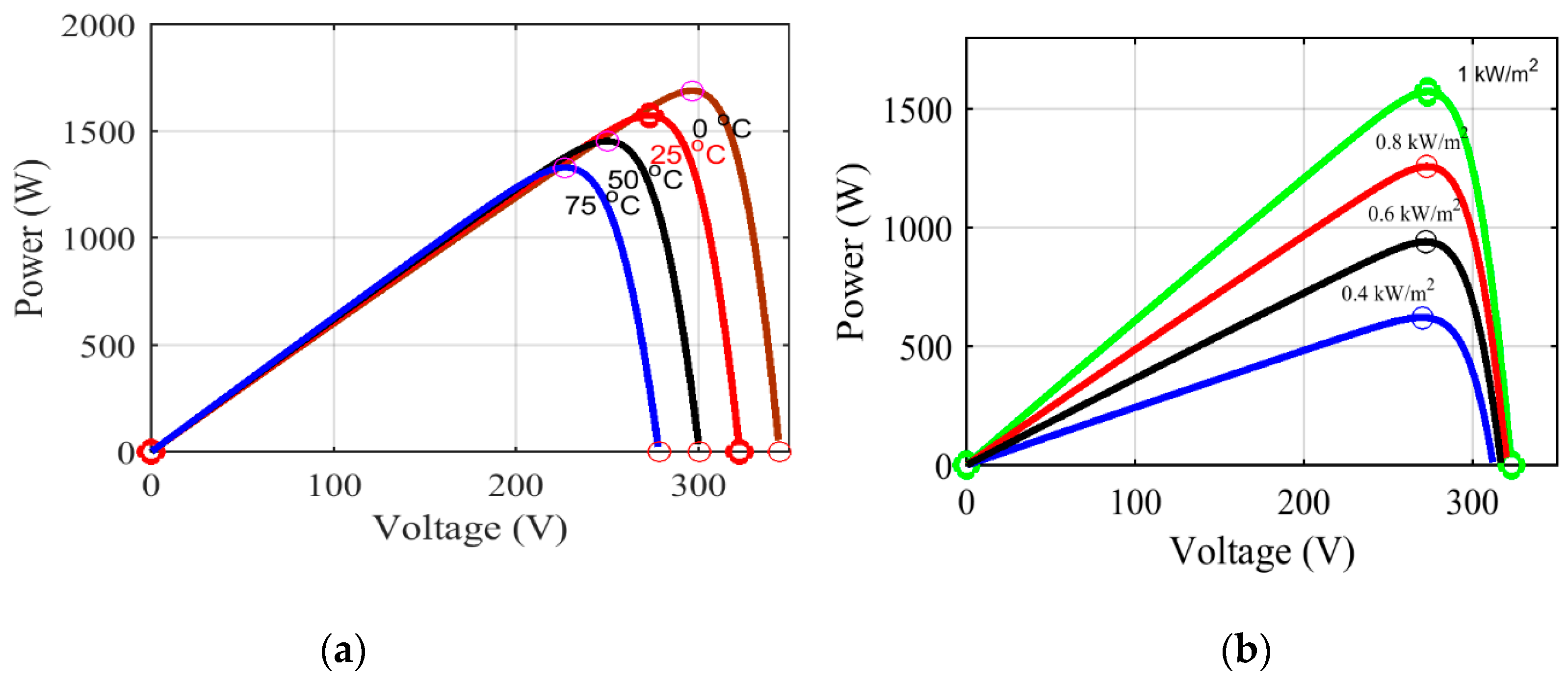
Among all renewable energy sources (RESs), solar is a noise-free, pollution-free, and inexhaustible resource. PV systems are a growing industry. Since the advent of the solar cell in the 1970s, the efficiencies of solar cells increased significantly. Solar energy is reliable, cheap, and abundant. Operating temperature and irradiance significantly affect the power an array can deliver [5]. The solar cell parameters are nonlinear by nature [6]. For a given pattern of shaded irradiance, the maximum available power is associated with a unique point on the power-voltage (P–V) curve, commonly known as the global maximum power point (GMPP), as shown in Figure 1 and Figure 2. The control action is applied to force the PV system to operate at the GMPP with the highest efficiency possible. MPPT increases output power significantly. Dynamic irradiance complicates the task of maximum power point tracking (MPPT) due to the existence of multiple local maxima (LM) [7]. The classical perturb and observe (P&O) and incremental conductance (IC) cannot distinguish between local solutions due to a single point of operation. At LM, P&O and IC produce oscillations and cause the dissipation of available power. To minimize oscillations, the step size is reduced, which takes a toll on convergence speed. On the other hand, a larger step size, although increasing rise time, results in higher oscillations in the steady state. So, there is a tradeoff between convergence speed and efficiency.
The effects of changes in temperature and irradiance are shown in Figure 1 and Figure 2. The irradiance has significant effects upon the current output ( I ). The magnitude of output power is directly proportional to irradiance intensity. The temperature has a predominant effect upon the MPP point and voltage, specifically open-circuit voltage ( V o c ). The output power is inversely proportional to the operating temperature [8].
A PV system is shown in Figure 3. A DC-DC boost converter is utilized for load interface and control action via a pulse width-modulated (PWM) control action provided by the duty cycle.
Photovoltaic characteristics are dependent upon irradiance, weather conditions, operating temperature, manufacturing technology, and mounting techniques [9]. Photovoltaic resources have been utilized in domestic PV systems, commercial solar parks, satellites, and remote small-scale utilities [10]. The efficiency of a PV system is a combination of the PV array (17–42%), inverter (up to 95%), and MPPT (98%) [11]. Modern control systems focus on MPPT to improve efficiency. Already existing systems also utilize improvised control with updated algorithms to maximize output. MPPT techniques are classified into offline, online, and hybrid methods. The offline methods make use of predefined parameters and mathematical models of a PV array to track MPPT and do not consider actual output power. The drawbacks of such systems are that they cannot detect the maximum power point during rapidly changing irradiance. Online methods, i.e., incremental conductance (IC) [12], perturb and observe (P&O) [13], and hill climbing (HC), measure the actual output power. The input and output power difference is utilized for decision making. Direct control is utilized to decide to either increase or decrease control parameters. The hybrid methods are applied in two steps. In the first step, general regression neural networks (GRNN), genetic algorithms (GAs), fuzzy, or artificial neural networks (ANNs) integrated with PID controllers are optimized according to the desired parameters. The second step involves the usage of optimized parameters for typical MPPT control action [11,12,14,15,16,17,18,19,20,21,22,23].
Although these methods are effective in tracking GM, there are some problems, like multiple LM, steady-state fluctuations, and oscillations that cannot be tackled. Heuristic algorithms like particle swarm optimization (PSO) and multiple knapsack (MKP) are successfully used for the accurate identification of global maxima (GM) [24]. In hybrid models of MPPT, advanced methods are used to maximize PV outputs. P&O, HC, and IC are the most common MPPT techniques because of their simplicity of implementation and integration with multiple heuristic algorithms to utilize power management controllers with renewable energy resources effectively.
Starting from the development of the PV mathematical model, different techniques are used to develop a comprehensive mathematical model of PV cells and arrays. This modeling is done based on the predefined characteristics of the module. A more advanced approach also considers the real-time changes in P–V characteristics due to temperature, changes in resistances due to load, etc. however, a PV cell equivalent circuit model, single diode model, double diode model, simplified PV model, and current source model are used to emphasize different controlling techniques in different types of MPPT algorithms [25].
The development of intelligent control and nature-inspired heuristic algorithms has enabled us to tackle problems like hotspot formation, non-uniform temperature spikes, partial shading, and other encapsulation failures that cause a loss of output power in a standard module. A defected module degrades the performance of the array, and consequently the whole system starts to underperform.
A PID controller is utilized independently or in combination with P&O and IC to enhance the transient and steady-state responses. To further enhance the output power and find global maxima, PSO, GAs, and ant colony optimization (ACO) are used. The hybrid approach to tune PID-PI controllers and DC-DC converters to obtain maximum power has been studied in several papers and they show the superior performance in terms of computation power [26,27,28].
Modern controlling action includes robustness, accuracy, and the fast tracking of MPP. Variable step size, fuzzy logic controllers (FLZ), Hybrid particle swarm optimization (HPSO), neural networks (NNs), and GRNNs are utilized to implement real-time control action. Our study focuses on the utilization of a modified GA to fine-tune a PID controller to optimize boost converter output for tracking MPP [29].
An ANN-PI [30] controller is compared with IC in [31]. GMMPT PSO [32]-based models are reviewed. An MPPT controller and its results are compared, exhibiting a better performance of ANN-PI, especially under partial shading conditions (PSCs). An ANN-PI controller in [30] is compared with an IC MPPT controller, and the results show a better performance of ANN-PI, especially under PSCs. In [33], a GA-based MPPT is utilized. The work focuses on avoiding LM conventional MPPT issues with a GA-based GM-based algorithm to avoid trapping the controller in LM. As for a P&O system embedded in a GA, this system does not need pre-setup and can be applied to any PV model. The successful tracking of MPP is achieved by locating global maxima [34]. In [35], a GA is resettled/reinitialized at the start of every population, raising the question of genetic pool and crossover. The initial population is reset in case of a large change in parameters like irradiance, temperature, or load, which have to be compensated. The method of introducing an extremely small series resistance in the mathematical model along with high crossover and mutation probabilities provides similar functionality. Although it can help to find global maxima in a very small population, in case of higher mutation and crossover steady-state responses, overshoot can be significantly higher. The larger population requires more computational power. Ahmed et al. in [36] compared the performance of a GA with GA-ANN power tracking efficiency while providing a better solution. Still, a lag in initial controlling action by the GA-ANN is observed because of the first few iterations, during which control action is not optimized. Although there are transient state lags, the steady-state response is better as compared to an ANN. This is the reason PID-GA tuning has been preferred, which makes use of not only predefined control action initially but it is also fine-tuned as the control action time progresses [37]. Chicken swarm optimization (CSO) is a new genetic algorithm based upon a biological algorithm in which initial positions are arranged in chaotic sequence. Using this technique, the risk of falling into an LM trap is avoided. Multiple peak curves are detected effectively and global maxima tracking is done in a stable manner [38].
In light of the literature review, the existing techniques lack efficient MPPT tracking, slow convergence, and exhibit oscillations around MPP. The common requirement from an MPPT controller is fast GM tracking, high efficiency, robustness, and zero oscillations around MPP. The proposed GAIC MPPT controllers successfully overcome the shortcomings of existing P&O controllers by the adaptive change in step size of the modified IC. This is achieved by the offline tuning of PID gains by the GA to enhance the online step size of the IC using GA. The comparative analysis shows the effectiveness under fast varying irradiance and temperature case studies.

2. PV System Model and Characteristics

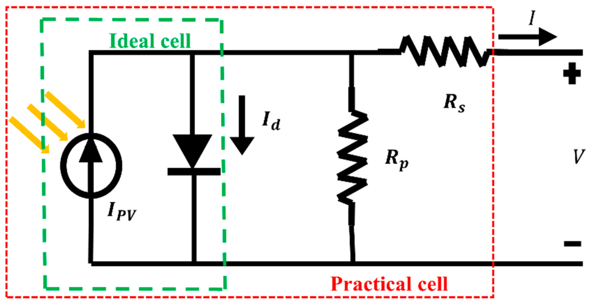
A single-diode equivalent model is presented in Figure 4. The nonlinear characteristics of operating temperature and irradiance dynamics are also incorporated. The PV cell acts as a current source when sunlight falls upon it. Ideally, it can be presented as a single diode model. To practically incorporate real behavior of the PV cell, a series ( R s ) and a parallel resistance ( R s h ) are added [11]. This edition incorporates the leakage current losses, junction resistances, etc. The ideal is given in Equation (1) and practical models are given by Equation (2) [39].
I = I p v I o exp ( V d n V t 1 )
I = I p v I o exp ( V d I R s n V t 1 ) ( V I R s R s h )
where I is the output current, I o is the saturation current, V stands for voltage, k is the Boltzmann constant (1.6021 × 10⁻²³ J/K), V t is the thermal voltage, and q is the electron charge (1.6021 × 10⁻¹⁹ C). the parameters of Figure 4 are presented in Table 1.
V t = n k T q
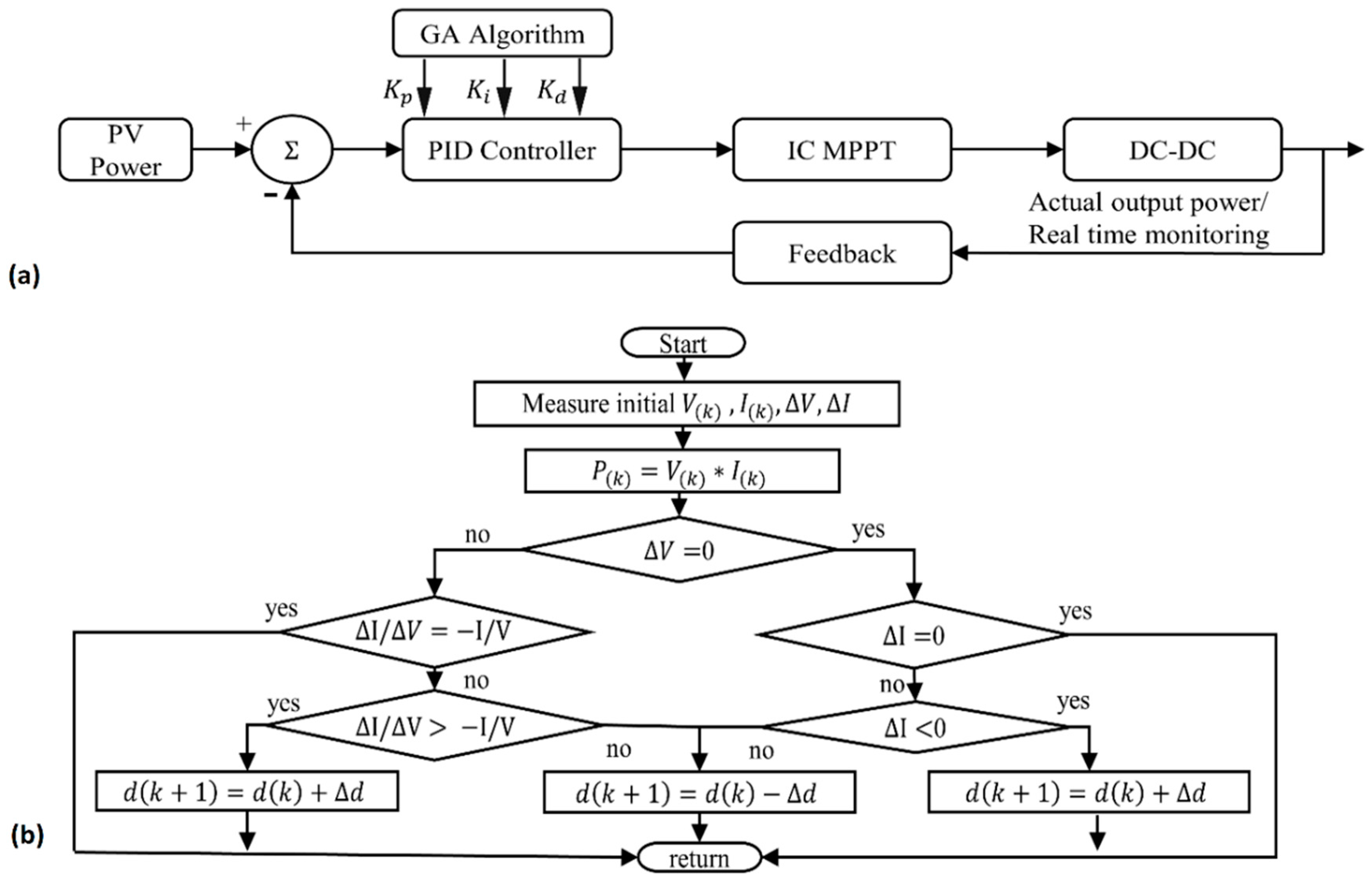
The drawback of a large step size is handled in modified IC-based step size MPPT. Improved tracking in both the dynamic and steady state is still an issue. A new PID controller with a GA is proposed in this paper to tune boost the converter’s input duty cycle for maximizing PV output power, as shown in Figure 5. The results of the comparative study are studied and show remarkable improvement as compared to classical MPPT in terms of response time, overshoot, and ripple [25]. A brief comparative study of literature review is given in Table 2.

Boost Converter

The boost converter, as the name suggests, steps up the voltage. In the boost DC-DC converter, the output voltage is higher than the input, including in the floating boost topology, where the input does not share the reference to the input voltage. Converters are utilized in supply rails that require a higher voltage as compared to the available DC sources similar to our case where we have to generate a standard voltage output with high efficiency and an ultralow standby current with small size wearable, portable, and reliable functionality in a PV module grid system. The PV module used in this study is SunPower SPR-315E-WHT-D and its electrical characteristics are given in Table 3. The PV panel used in this study is Equation (4) gives the relationship between control action and output [44].
D = 1 V i n V o

3. Modified GA-IC

Many researchers have successfully implemented the P&O algorithm for MPPT [22,45]. Although P&O successfully tracks with reasonable efficiency, in MPPT, it oscillates back and forth and causes significant steady-state errors [12]. On the other hand, the new IC has the advantage of the determination of MPP and the IC-based algorithm proposed has overcome the shortfall of P&O. The ratio of change in output conductance is equal to the negative output conductance. Conductance is an electrical term and is a ratio of current to voltage as given by Equation (5). At the MPP, the slope of the curve is zero [46].
d V / d I = V / I   ( = V / I a t   M P P > V / I l e f t   o f   M P P < V / I r i g h t   o f   M P P )
The change in output power with respect to voltage is given by Equation (6).
d P d V = I + V x d I d V

3.1. Proposed GA-Based Adaptive Step Size IC MPPT

The main objective of the PV control system is to provide maximum output power for given weather irradiation and temperature conditions. Energy optimization for the load is done by using a DC-DC converter that provides a controlling interface between the PV array and load. The duty cycle is utilized to produce a reference voltage for DC-DC boost converter pulse width modulation (PWM). The duty cycle is modified by adding a fixed step size change to perform the controlling action. This works presents a novel modified step size technique that utilizes a modification in the step size of classical IC. GA is used to optimize the gain of the PID controller, which alters the magnitude of step change (∆d) in both transition and steady states. This system is presented in the form of a block diagram in Figure 5a.

3.2. Genetic Algorithm

In biological evolution, species, depending upon their positive or negative success in reproduction and survival in a particular environment, are successfully able to reproduce further and pass their traits to future generations. Because the generation of variety and differential survival through reproduction, evolution takes place. This is the basic biological evolution concept inspired by evolutionary computation (EC). Genetic algorithms are computational models inspired by evolution. The potential solution to a problem is encoded in chromosomes. Each chromosome carries a unique set of traits, i.e., a solution for the application of recombination operators to preserve critical information. Just like NNs, the GA is also considered as a function optimizer. To date, GAs have been applied to a broad range of applications. The widespread applicability, inherent parallelism, and global perspective are the main reasons for the popularity of GAs in the search for and optimization of problems.

3.3. GA-Based Tuning of PID Controller

A PID controller is utilized as an indirect control action. Each control parameter is encoded as a binary string of chromosomes. The PID controller is mathematically given by Equation (7) [47].
u ( t ) = K p e ( t ) + K i 0 t e ( t ) d τ + K d d e ( t ) d t
where K p is the proportional gain, K i is the integral gain, and K d is the derivative gain. Optimization is done to minimize the e ( t ) given by Equation (8).
e ( t ) = S P P V ( t )
where e ( t ) is the error in terms of reference or set point (SP) and process value (PV), t is the instantaneous time, and τ is the variable of integration that takes values from 0 t at the instant of operation.
A genetic algorithm is used to tune the gains of the PID controller. Parameters K p ,   K d , and K i are encoded as chromosome binary strings. Each chromosome is assigned 16 bits. The total length of the string is 48 bits. Selection is applied to a group of chromosomes to obtain a mating pool. In the GA, the main reason for obtaining a mating pool is to select healthy individuals for reproduction. In our case, the selection of parents is done on the basis of fitness proportionate selection, roulette selection assigns a fitness to a possible solution in a population which is associated with the probability of the selection of each chromosome. The solutions with higher fitness are less likely to be eliminated. It gives a healthy first generation to begin with.

3.4. Operation of the GA

The GA starts with a string of fixed length code, representing possible solutions. Potential solutions are known as chromosomes. Each chromosome is tested against a fitness function and is assigned a fitness value. Afterward, three different operations are applied to the population of chromosomes. These operations are:
  • Selection: the selection is applied to the population to obtain the fittest mating pool.
  • Crossover: crossover is an operation applied to the strings of the mating pool in which two randomly selected strings swap some portion of the string between each other.
  • Mutation: in mutation, the lower bits of string data of an individual chromosome are inverted, 0–1 and 1–0, which generates newer traits and diversity in the solution space.
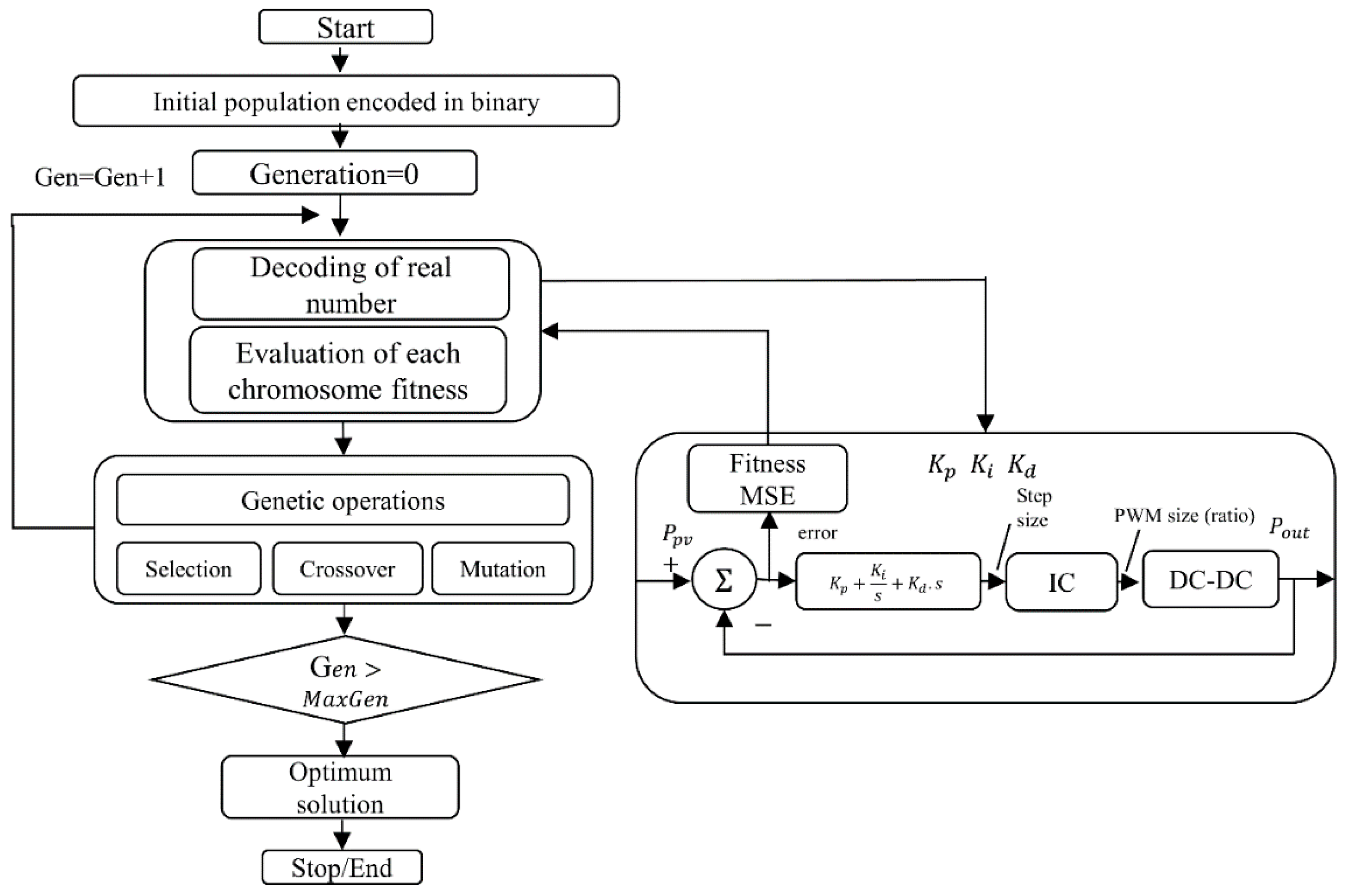
The iteration of these operations gives rise to a new generation. Every new generation represents a better result or optimization of the solution. At the end of one iteration, the stopping criterion is checked. The stopping criterion can be a predefined time limit, the number of iterations, or population convergence. A flowchart of a GA is shown in Figure 6.

3.4.1. Crossover

For the next generation, crossover is performed, and new individuals contain genetic material from both of the parents. We applied single point crossover in our case, as illustrated by Figure 7. Mutation, as shown in Figure 8, is a genetic operation by means of which it is ensured that bio-genetic diversity in next generation is preserved.

3.4.2. Mutation

The fitness is calculated for each chromosome by an equivalent real number binary magnitude representing the gain signal of the PID signal. Each iteration gives a set of values passed to the PID controller in order to compute the control signal of the system, as shown in Figure 9. The role of mutation is to help us explore more of the solution space. Mutation is introduced by complementing the lower nibble bits of the binary string. It stops the population from falling into local minima.

3.4.3. Fitness Function

The fitness function is presented by Equation (9). Most fitness functions make use of overshoot, rise time, settling time, steady-state error, or a combination of any of these criteria, and any one of these can be potential fitness function. We have made use of a combination of scaling factor and integral square error (ISE) [40]. The parameters α and β are both given equal preference, i.e., α = β = 0.5 .
F = α · o v e r s h o o t + β · I S E
Peak overshoot is calculated using Equation (10).
p e a k   o v e r s h o o t = o v p e a k o v s s   o v s s · 100 %
Overshoot is calculated using Equation (11).
o v e r s h o o t = m a x ( P o u t P r e f )
ISE is calculated using Equation (12).
I S E = 0 τ ( P r e f P o u t ) 2 d t

3.5. Experimental Implementation of Modified GA-IC MPPT

Table 4 gives the parameters of the GA under implementation. Table 5 presents the optimized sets of the PID controller. The size of the population increases efficiency but takes a toll on computation, so it does iterations. The crossover probability makes use of the transfer of characteristics being transferred to the next generation. Mutation introduces new traits. It diversifies the solution and eliminates stagnation in each iteration. Figure 9 gives the detailed flow of proposed MPPT control action.
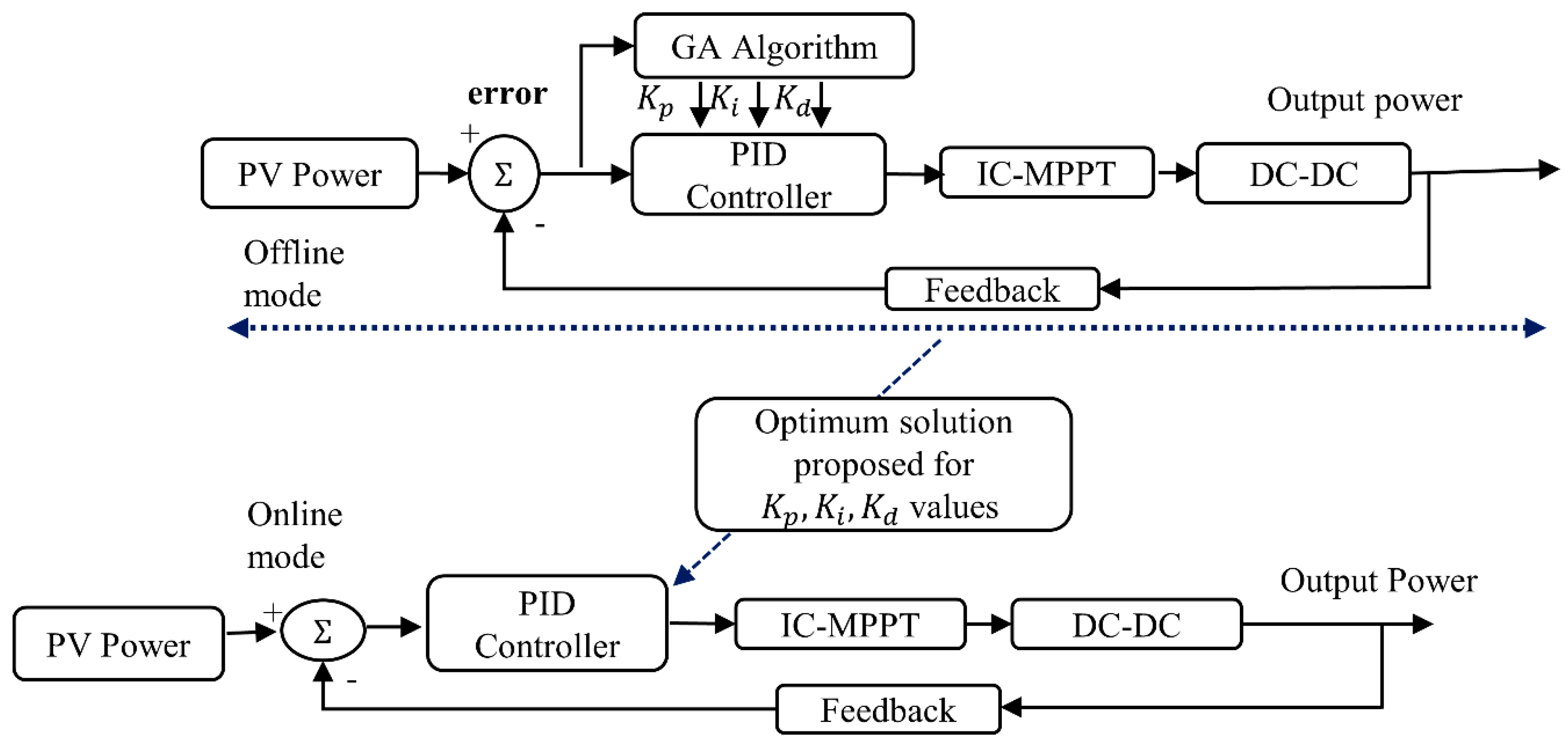
Up till now, the GA has been utilized to optimize the performance of the PID controller, and at this stage, the PID controller and GA are operated in offline and online modes.
  • Offline mode: utilized in tuning PID gains (Figure 10).
  • Online mode: tested PID parameters are applied to track GM via incremental conductance. The output of the PID controller controls the step size of incremental conductance block.
The updated IC block on each step generates the corresponding variable duty cycle signal. The ratio of the duty cycle is the controlling factor of the DC-DC boost converter, which regulates the output of the PV array at MPP.
4. Results and Discussion

The proposed technique is extensively tested for the validation of robustness and applicability. A comparison is made with classical P&O algorithm. The P-V and I-V curves represent the intrinsic nonlinearity of the PV system. Two cases of irradiance and one for temperature will be discussed. The input patterns of irradiance and temperature are given for case 1, case 2, and case 3 and are presented in Figure 11, Figure 12 and Figure 13, respectively. Table 6 gives the test pattern of the results. Case 1 deals with sudden large change in input irradiance. Figure 11 shows the irradiance pattern. Sudden changes in input irradiance are observed at random intervals. In case 2, a gradual change in irradiance at certain random intervals is observed and dynamic operating temperature is dealt with in case 3. Figure 2 mimics the effects of changing temperature upon the standalone PV system.
The results of experimental simulations show that a significant improvement is achieved in minimizing oscillations, overshoot, and tracking time. Maximum average power, efficiency, response time, tracking, ripple, and overshoot are discussed in this section. The maximum average power is calculated for the entire period of simulation. Ripple and overshoot are observed and calculated at the point where each algorithm first reaches closest to the MPP and then settles at the MPP. These values vary in certain parameters, i.e., initialization, error signals, the rate of change of irradiance, and initial step sizes. Response time shows the robustness of the control system. Meanwhile, settling time represents the convergence of the applied technique. Faster settling improves the transient and convergence steady-state responses of the implemented techniques.

4.1. Case 1

The pattern of irradiance is given in Figure 11, and initially in time period zero to 1.5 s, 1000 W/m2 irradiance is applied. Afterwards, abrupt changes in irradiance levels are observed at 1.5 s, 3 s, and 4.5 s. The corresponding changes in irradiance are from 1000 W/m2 to 400 W/m2, 400 W/m2 to 800 W/m2 to 600 W/m2 to 400 W/m2 to 800 W/m2 respectively. GA-IC and P&O reach the MPP in 0.012854 and 0.0289 s, respectively, and the settling times around the MPP are 0.1754 s and 0.3285 s, respectively. Similarly, the changes in irradiance at 1.5 s from 1000 W/m2 to 400 W/m2 forces both algorithms to re-track the MPP. GA-IC takes 0.09 seconds, 0.03 seconds faster as compared to P&O, which takes 0.12 seconds to re-track the MPP. The overshoot at 0.01285 s for GA-IC is 49.2% less than the 100.6 watts dissipated by P&O at 0.0289 s. The robustness of the proposed technique is evident from the faster tracking and even faster settling time at the MPP. Ripples are reduced by 94.77%, which is a significant reduction. At 0.3142 s, ripples are observed in Figure 14 and Figure 15 with a magnitude that varies from 18–23 watts by P&O. GA-IC ripples are reduced to 1–2 watts as shown in Figure 15 and Figure 16, reducing ripple size by up to 94%. A smoother output power is achieved as shown in Figure 17 power zoom. The voltage and current transients are given by Figure 18, Figure 19, Figure 20 and Figure 21.

4.2. Case 2

This case gives the most effective test pattern for P&O to compete with the proposed GA-IC technique. The irradiance pattern is presented by Figure 12, showing the gradual and continuous increase in irradiance levels. Starting from t = 0 to 1 s and 700 W/m2, from 1–1.5 s it is gradually changed from 700 W/m2 to 790 W/m2 and remains constant till 2.5 s. Similarly, it changes from 790 to 898 W/m2 in the next 0.5 s. Eventually, it reaches 1000 W/m2. The rate of change of in the irradiance is kept at 216 watt/s. Fast recovery is needed to minimize power loss due to lag in tracking the MPP. Tracking the MPP with efficiency is the desired outcome of this test pattern. The control action given by duty cycle is compared in Figure 22 and detailed zoom in Figure 23. The efficiency of P&O and GA-IC is 98.5% and 99.2%, respectively, for power conversion as shown in Figure 24 and Figure 25. The response time of the proposed GA-IC is 14.78% faster. This indicates that the proposed technique is faster in terms of tracking a gradually changing MPP. Moreover, the oscillations caused by P&O, which continuously dissipate, on average, 26.8 watts of power, are reduced by 97.3%. This significant improvement in design saves up to 25 watts of power, adding another 1% of efficiency in power conversion by MPPT. Overshoot in both cases is designed to be at a minimum. This is done by gradually adding irradiance from a lower to a high level. The reason for such a choice is to provide a good understanding of the tracking capability of the GA-IC under a transitioning MPP. The voltage and current transients are given by Figure 26, Figure 27, Figure 28 and Figure 29.

4.3. Case 3

Case 3 deals with the effects of temperature on the PV system. The duty cycle is given in Figure 30 and Figure 31. The voltage of the PV cell is inversely dependent upon the operating temperature. An increase in temperature reduces the output voltage of the PV module, hence taking a toll on the extractable PV power. A comparison between P&O and the GA-IC under test case 3 is given in Figure 32. The results indicate the superior performance of the proposed technique over traditional P&O. The GA-IC response time is 0.00365 s and the settling time is 0.062 s. P&O, on the other hand, takes 0.0135 s and 0.1153 s, respectively. The GA-IC is, on average, 39% faster in tracking the MPP in comparison to P&O. The overshoot for the GA-IC is 34.8% less as compared to P&O as shown in Figure 33. Ripples are almost negligible, i.e., <1 watt. The GA-IC successfully reduced the oscillations produced by P&O by 92.8%, adding 1.72% more power. The overall efficiency achieved by the proposed technique is up to 98.4%, hence making this case another result for the superior performance in terms of power convergence, robustness, and MPPT. The voltage and current transients along with detailed behavior are given by Figure 34, Figure 35, Figure 36 and Figure 37.

5. Performance Comparison

This section deals with the overall comparison of the proposed GA-IC-based MPPT controller with P&O in terms of tracking time, settling time, steady-state oscillations, ripples, and algorithm complexity. Table 7 gives a comprehensive summary of the results.

5.1. Tracking

The tracking of the MPP is the main objective of the PV control system. Figure 33 depicts the relative performance for power, similarly, Figure 31 shows the duty cycle comparison. Mostly, the comparisons made do not utilize absolute values. Rather they provide a range of operation which gives indications of the relative superior performance. In this article, absolute values, the range of operation, and statistical data analysis are done in order to establish the dominance of the proposed technique based on strong evidence. All figures numerically indicate a superior performance in tracking MPP and hence effectively maximizing absolute power. In terms of power, P&O performs reasonably, yet the proposed GA-IC technique is proven to be better in attaining the MPP rapidly. P&O step size can be increased or decreased to further enhance its tracking capability. P&O has a fairly effective dynamic tracking but the proposed technique still outperforms P&O. The GA-IC takes 0.00365–0.062 s as compared to P&O, which takes 0.0135–0.3285 seconds to reach the MPP in the transient state from zero output power to the MPP in applied cases. The GA-IC is 46.8–47% faster in tracking the MPP.

5.2. Settling Time

Tracking and re-tracking need to be done when a sudden large change in irradiance or temperature shifts the MPP significantly. Settling time is the time needed by a technique or algorithm to generate its best output and consistently stay at the same point under a similar set of system conditions. The sudden change in input parameters causes the displacement of the MPP, while already being at the MPP. The robustness of an algorithm is tested when it re-tracks the MPP. P&O can detect a change in any sampling time and hence provides good competition to the GA-IC. P&O and the GA-IC tackle this problem by reinitializing control action to reach a new MPP. The control signal of P&O only tackles the direction of change. It has the lowest compatibility with the scale of change. Re-initiation is mostly avoided for small-scale changes in input conditions of the system under consideration. The good re-tracking capability of the GA-IC is due to the control signal generated, which also takes the scale of parameters to change, and a larger change generates a larger control signal change and it gradually decreases as the difference between the operating point and the MPP decrease. The effect of this scheme is quicker re-tracking. It takes 0.004–0.01 seconds to re-track as compared to P&O (0.05–0.35 s). The GA-IC is up to 47% faster in re-tracking.

5.3. Steady-State Oscillations

The most advantageous region of operation for the PV system is in the steady-state region. P&O loses 1.5% to 5.4% of PV array power. P&O has an efficiency average of up to 96.5% depending upon the irradiance pattern and temperature. The proposed GA-IC, due to the effective exploitation mechanism, reaches a maximum efficiency of up to 98.89%, significantly outperforming P&O. Usually, the fluctuations and power oscillation amount to 0.018% of the total output power losses, hence it is negligible at larger scales.

5.4. Ripples

P&O case 1, case 2, and case 3 generated ripple magnitudes of 15.6 W, 26.8 W, and 14 W, respectively. The performance enhancement in output power is depicted in Figure 17 for case 1 and Figure 25 for case 2. Analysis yields that power fluctuations continuously cause a loss of power. It amounts to a minimum of 35 W at any instance of operation. Oscillations produced by the GA-IC are negligibly small and cause a power dissipation of 1–5 W. Comparatively, the GA-IC achieves ripples/oscillations up to 17 times smaller.

5.5. Algorithm Complexity

The complexity of an algorithm is gauged for the MPPT problem by implementing it in a programming language according to the tuning of the number of parameters. The number of tunable parameters in both cases is different. P&O has only one tunable parameter, which is step size Δ d . Hence, it is said to be fairly simple. However, the GA-IC makes use of PID gains fine-tuned by the GA. The process is described in Section 2. The gain parameters of the PID controller, K p ,   K d , and K i , are tuned by the GA. The complexity of the algorithm also contributes to its implementation in a programming language, the computational power, and the hardware needed. The proposed technique makes use of the same sensors as P&O and is executable in low-cost 8-bit microcontrollers. Hence, it is evident that its cost-effective implementation is doable.

5.6. Results Summary

A new MPPT technique is introduced using GA-based PID tuning for the GA-IC MPPT control system of a standalone PV system. The technique is tested against traditional P&O. A comprehensive study is done and the results are discussed in detail in Table 7 and Table 8. Case 1 and 2 tackle the phenomenon of abruptly changing irradiance and gradually varying irradiance. Case 3 takes into account the effects of varying the operating temperature. A detailed study in terms of statistical analysis and experimental simulations are done, which shows that the proposed GA-IC technique outperforms traditional P&O in performance, reliability, and efficiency. The main objectives achieved by this study are:
  • Establishment of new GA-IC-based MPPT technique.
  • Application and validation of the GA-IC by experimental simulations.
  • Improvising power gain under gradually changing irradiance.
  • Setting up a cost-effective and easy to implement MPPT controller for small-scale standalone PV systems.
  • Minimization of response time, overshoot, and ripples.
  • Successful integration of a variable IC with a GA for PV MPPT.

6. Conclusions

In this study, a new MPPT technique is presented for standalone PV systems. GA is used to tune the PID controller to generate the varying step size of the IC. The simulations and results validate the reliability, functionality, and validity of the proposed model. The presented work successfully overcomes the shortcomings of P&O. The simulation environment of varying irradiance and temperature is compared with the fixed-step P&O algorithm. Three case studies, namely fast-varying irradiance, continuously varying irradiance, and temperature are done. The results solidify the superior performance of the proposed MPPT controller. In light of the results, it is safe to conclude that the proposed MPPT controller outperforms the existing techniques in power tracking efficiency by 4.49%, it achieves a 56.4% quicker response time, and ripples are reduced by 94.77%, along with a 49.2% overshoot reduction as compared to optimized P&O.
The contributions of the article are:
  • Implementation of new MPPT technique for a standalone PV system.
  • The proposed technique successfully tracks the MPP for varying irradiance and temperature conditions.

Author Contributions

Conceptualization, A.F.M., Q.L.; methodology, A.F.M., Q.L., M.M.; software, A.F.M., M.M., M.I.K.; validation, A.F.M., M.M., M.I.K.; formal analysis, A.F., M.M., M.I.K.; investigation, A.F., M.M., M.I.K.; resources, Q.L., O.M.A.; data curation, A.F.M.; writing—original draft preparation, A.F.M.; writing—review and editing, A.F.M., M.M., M.I.K.; visualization, M.I.K.; supervision, Q.L., O.M.A.; project administration, Q.L., O.M.A.; funding acquisition, O.M.A. All authors have read and agreed to the published version of the manuscript.

Funding

The authors would like to extend their sincere appreciation to the researchers supporting project number (RSP-2020/61), King Saud University, Riyadh, Saudi Arabia.

Conflicts of Interest

The authors declare no conflicts of interest.

Abbreviations

List of Abbreviations
PSPartial shading
GAGenetic algorithm
PIDProportional integral differential
MPPTMaximum power point tracking
ICIncremental conductance
P&OPerturb and observe
Variables and Constants
I Output current
V Output voltage
I PV Cell current produced by actual solar arrays
I d Diode current
R   s   eq Equivalent series resistance
R s Series resistance
R p   eq Equivalent parallel resistance
R p Parallel resistance
I o Reverse saturation current
V T Thermal voltage of PV module
α Diode ideality factor
N s Number of cells connected in series
N p Number of cells connected in parallel
k Boltzmann constant = 1.38073 × 10 23   J / K
T Temperature of the p-n junction
q Electron charge = 1.6022 × 10 19   C
D Duty cycle
Δ d Step change

References

  1. Márquez-Ramos, L. The environmental impact of renewables. Int. J. Glob. Warm. 2018, 14, 143–158. [Google Scholar] [CrossRef]
  2. Du, P.; Matevosyan, J. Forecast system inertia condition and its impact to integrate more renewables. IEEE Trans. Smart Grid 2018, 9, 1531–1533. [Google Scholar] [CrossRef]
  3. Hafner, R.J.; Elmes, D.; Read, D. Promoting behavioural change to reduce thermal energy demand in households: A review. Renew. Sustain. Energy Rev. 2019, 102, 205–214. [Google Scholar] [CrossRef] [Green Version]
  4. Nuortimo, K.; Härkönen, J.; Karvonen, E. Exploring the global media image of solar power. Renew. Sustain. Energy Rev. 2018, 81, 2806–2811. [Google Scholar] [CrossRef] [Green Version]
  5. Borowy, B.S.; Salameh, Z.M. Optimum photovoltaic array size for a hybrid wind/PV system. IEEE Trans. Energy Convers. 1994, 9, 482–488. [Google Scholar] [CrossRef]
  6. Zhu, L.; Li, Q.; Chen, M.; Cao, K.; Sun, Y. A simplified mathematical model for power output predicting of Building Integrated Photovoltaic under partial shading conditions. Energy Convers. Manag. 2019, 180, 831–843. [Google Scholar] [CrossRef]
  7. Hua, C.-C.; Kuo, W.-Y. A new maximum power point tracking method for PV string under PS condition. In Proceedings of the IEEE Conference on Energy Conversion (CENCON), Lumpur, Malaysia, 30–31 October 2017; IEEE: New York, NY, USA, 2017; pp. 1–4. [Google Scholar]
  8. Mansoor, M.; Mirza, A.F.; Ling, Q. Harris hawk optimization-based MPPT control for PV Systems under Partial Shading Conditions. J. Clean. Prod. 2020, 274, 122857. [Google Scholar] [CrossRef]
  9. Zsiborács, H.; Pintér, G.; Bai, A.; Popp, J.; Gabnai, Z.; Pályi, B.; Farkas, I.; Baranyai, N.H.; Gützer, C.; Trimmel, H. Comparison of thermal models for ground-mounted south-facing photovoltaic technologies: A practical case study. Energies 2018, 11, 1114. [Google Scholar] [CrossRef] [Green Version]
  10. Karki, R.; Billinton, R. Reliability/cost implications of PV and wind energy utilization in small isolated power systems. IEEE Trans. Energy Convers. 2001, 16, 368–373. [Google Scholar] [CrossRef]
  11. Javed, M.Y.; Murtaza, A.F.; Ling, Q.; Qamar, S.; Gulzar, M.M. A novel MPPT design using generalized pattern search for partial shading. Energy Build. 2016, 133, 59–69. [Google Scholar] [CrossRef]
  12. Liu, F.; Duan, S.; Liu, F.; Liu, B.; Kang, Y. A variable step size INC MPPT method for PV systems. IEEE Trans. Ind. Electron. 2008, 55, 2622–2628. [Google Scholar]
  13. Al-Diab, A.; Sourkounis, C. Variable step size P&O MPPT algorithm for PV systems. In Proceedings of the 12th International Conference on Optimization of Electrical and Electronic Equipment (OPTIM), Brasov, Romania, 20–22 May 2010; IEEE: New York, NY, USA, 2010; pp. 1097–1102. [Google Scholar]
  14. Boutasseta, N. PSO-PI based control of photovoltaic arrays. Int. J. Comput. Appl. 2012, 48, 36–40. [Google Scholar] [CrossRef]
  15. Hadjaissa, A.; Ameur, K.; Essounbouli, N. A GA-based optimization of a fuzzy-based MPPT controller for a photovoltaic pumping system, Case study for Laghouat, Algeria. IFAC-PapersOnLine 2016, 49, 692–697. [Google Scholar] [CrossRef]
  16. Jiang, L.L.; Maskell, D.L.; Patra, J.C. A novel ant colony optimization-based maximum power point tracking for photovoltaic systems under partially shaded conditions. Energy Build. 2013, 58, 227–236. [Google Scholar] [CrossRef]
  17. Karaboga, D.; Basturk, B. Artificial bee colony (ABC) optimization algorithm for solving constrained optimization problems. In Foundations of Fuzzy Logic and Soft Computing, Proceedings of the International Fuzzy Systems Association World Congress, Cancun, Mexico, 18–21 June 2007; Springer: Berlin/Heidelberg, Germany, 2007; pp. 789–798. [Google Scholar]
  18. Karaboga, D.; Gorkemli, B.; Ozturk, C.; Karaboga, N. A comprehensive survey: Artificial bee colony (ABC) algorithm and applications. Artif. Intell. Rev. 2014, 42, 21–57. [Google Scholar]
  19. Mirjalili, S. Dragonfly algorithm: A new meta-heuristic optimization technique for solving single-objective, discrete, and multi-objective problems. Neural Comput. Appl. 2016, 27, 1053–1073. [Google Scholar] [CrossRef]
  20. Mirjalili, S.; Hashim, S.Z.M. A new hybrid PSOGSA algorithm for function optimization. In Proceedings of the International Conference on Computer and Information Application (ICCIA), Tianjin, China, 2–4 November 2010; IEEE: New York, NY, USA, 2010; pp. 374–377. [Google Scholar]
  21. Rizzo, S.A.; Scelba, G. ANN based MPPT method for rapidly variable shading conditions. Appl. Energy 2015, 145, 124–132. [Google Scholar] [CrossRef]
  22. Xiao, W.; Dunford, W.G. A modified adaptive hill climbing MPPT method for photovoltaic power systems. In Proceedings of the IEEE 35th Annual Power Electronics Specialists Conference PESC, Aachen, Germany, 20–25 June 2004; IEEE: New York, NY, USA, 2004; pp. 1957–1963. [Google Scholar]
  23. Yang, X.-S.; Deb, S. Cuckoo search via Lévy flights. In Proceedings of the World Congress on Nature & Biologically Inspired Computing (NaBIC), Coimbatore, India, 9–11 December 2009; IEEE: New York, NY, USA, 2009; pp. 210–214. [Google Scholar]
  24. Mendez, E.; Ortiz, A.; Ponce, P.; Macias, I.; Balderas, D.; Molina, A. Improved MPPT Algorithm for Photovoltaic Systems Based on the Earthquake Optimization Algorithm. Energies 2020, 13, 3047. [Google Scholar] [CrossRef]
  25. Mirza, A.F.; Mansoor, M.; Ling, Q.; Yin, B.; Javed, M.Y. A Salp-Swarm Optimization based MPPT technique for harvesting maximum energy from PV systems under partial shading conditions. Energy Convers. Manag. 2020, 209, 112625. [Google Scholar] [CrossRef]
  26. Mansoor, M.; Mirza, A.F.; Ling, Q.; Javed, M.Y. Novel Grass Hopper optimization based MPPT of PV systems for complex partial shading conditions. Sol. Energy 2020, 198, 499–518. [Google Scholar] [CrossRef]
  27. Mirza, A.F.; Ling, Q.; Javed, M.Y.; Mansoor, M. Novel MPPT techniques for photovoltaic systems under uniform irradiance and Partial shading. Sol. Energy 2019, 184, 628–648. [Google Scholar] [CrossRef]
  28. Javed, M.Y.; Mirza, A.F.; Hasan, A.; Rizvi, S.T.H.; Ling, Q.; Gulzar, M.M.; Safder, M.U.; Mansoor, M. A Comprehensive Review on a PV Based System to Harvest Maximum Power. Electronics 2019, 8, 1480. [Google Scholar] [CrossRef] [Green Version]
  29. Gil-Antonio, L.; Saldivar, B.; Portillo-Rodríguez, O.; Ávila-Vilchis, J.C.; Martínez-Rodríguez, P.R.; Martínez-Méndez, R. Flatness-based control for the maximum power point tracking in a photovoltaic system. Energies 2019, 12, 1843. [Google Scholar] [CrossRef] [Green Version]
  30. Paul, S.; Thomas, J. Comparison of MPPT using GA optimized ANN employing PI controller for solar PV system with MPPT using incremental conductance. In Proceedings of the International Conference on Power Signals Control and Computations (EPSCICON), Thrissur, India, 6–11 January 2014; IEEE: New York, NY, USA, 2014; pp. 1–5. [Google Scholar]
  31. Liu, Y.-H.; Chen, J.-H.; Huang, J.-W. A review of maximum power point tracking techniques for use in partially shaded conditions. Renew. Sustain. Energy Rev. 2015, 41, 436–453. [Google Scholar] [CrossRef]
  32. Abdourraziq, M.A.; Maaroufi, M.; Ouassaid, M. A new variable step size INC MPPT method for PV systems. In Proceedings of the International Conference on Multimedia Computing and Systems (ICMCS), Marrakech, Morocco, 14–16 April 2014; IEEE: New York, NY, USA, 2014; pp. 1563–1568. [Google Scholar]
  33. Ramaprabha, R.; Gothandaraman, V.; Kanimozhi, K.; Divya, R.; Mathur, B. Maximum power point tracking using GA-optimized artificial neural network for Solar PV system. In Proceedings of the 1st International Conference on Electrical Energy Systems (ICEES), Chennai, India, 3–5 January 2011; IEEE: New York, NY, USA, 2011; pp. 264–268. [Google Scholar]
  34. Shaiek, Y.; Smida, M.B.; Sakly, A.; Mimouni, M.F. Comparison between conventional methods and GA approach for maximum power point tracking of shaded solar PV generators. Sol. Energy 2013, 90, 107–122. [Google Scholar] [CrossRef]
  35. Deshkar, S.N.; Dhale, S.B.; Mukherjee, J.S.; Babu, T.S.; Rajasekar, N. Solar PV array reconfiguration under partial shading conditions for maximum power extraction using genetic algorithm. Renew. Sustain. Energy Rev. 2015, 43, 102–110. [Google Scholar] [CrossRef]
  36. Ali, A.; Twala, B.; Marwala, T. Performance of MPPT in Photovoltaic Systems Using GA-ANN Optimization Scheme. In Artificial Intelligence and Evolutionary Computations in Engineering Systems; Springer: New York, NY, USA, 2018; pp. 39–49. [Google Scholar]
  37. Wu, Z.; Yu, D.; Kang, X. Application of improved chicken swarm optimization for MPPT in photovoltaic system. Optim. Control. Appl. Methods 2018, 39, 1029–1042. [Google Scholar] [CrossRef]
  38. Li, S. A variable-weather-parameter MPPT control strategy based on MPPT constraint conditions of PV system with inverter. Energy Convers. Manag. 2019, 197, 111873. [Google Scholar] [CrossRef]
  39. Anani, N.; Ibrahim, H. Adjusting the Single-Diode Model Parameters of a Photovoltaic Module with Irradiance and Temperature. Energies 2020, 13, 3226. [Google Scholar] [CrossRef]
  40. Harrag, A.; Messalti, S. Variable step size modified P&O MPPT algorithm using GA-based hybrid offline/online PID controller. Renew. Sustain. Energy Rev. 2015, 49, 1247–1260. [Google Scholar]
  41. Shankar, G.; Mukherjee, V. MPP detection of a partially shaded PV array by continuous GA and hybrid PSO. Ain Shams Eng. J. 2015, 6, 471–479. [Google Scholar] [CrossRef] [Green Version]
  42. Huynh, D.C. An Improved Incremental Conductance Maximum Power Point Tracking Algorithm for Solar Photovoltaic Panels. Int. J. Sci. Res. 2014, 3, 342–347. [Google Scholar]
  43. Gupta, A.; Kumar, P.; Pachauri, R.K.; Chauhan, Y.K. Performance Analysis of Neural Network and Fuzzy Logic Based MPPT Techniques for Solar PV Systems. In Proceedings of the 6th IEEE Power India International Conference (PIICON), Delhi, India, 5–7 December 2014; IEEE: New York, NY, USA, 2014; pp. 1–6. [Google Scholar]
  44. Zhang, Y.; Ren, J.; Pu, Y.; Wang, P. Solar energy potential assessment: A framework to integrate geographic, technological, and economic indices for a potential analysis. Renew. Energy 2020, 149, 577–586. [Google Scholar] [CrossRef]
  45. Femia, N.; Petrone, G.; Spagnuolo, G.; Vitelli, M. A technique for improving P&O MPPT performances of double-stage grid-connected photovoltaic systems. IEEE Trans. Ind. Electron. 2009, 56, 4473–4482. [Google Scholar]
  46. Ali, A.; Almutairi, K.; Malik, M.Z.; Irshad, K.; Tirth, V.; Algarni, S.; Zahir, M.; Islam, S.; Shafiullah, M.; Shukla, N.K. Review of Online and Soft Computing Maximum Power Point Tracking Techniques under Non-Uniform Solar Irradiation Conditions. Energies 2020, 13, 3256. [Google Scholar] [CrossRef]
  47. Pathak, D.; Sagar, G.; Gaur, P. An Application of Intelligent Non-linear Discrete-PID Controller for MPPT of PV System. Procedia Comput. Sci. 2020, 167, 1574–1583. [Google Scholar] [CrossRef]
Figure 1. P-V characteristics curve of a PV solar cell (a) Temperature (b) Irradiance
Energies 13 04153 g001
Figure 2. Current-Voltage (I-V) characteristics curve of a PV solar cell (a) Temperature (b) Irradiance.
Energies 13 04153 g002
Figure 3. PV system with the proposed methodology block diagram.
Energies 13 04153 g003
Figure 4. Single-diode equivalent circuit of PV cell.
Energies 13 04153 g004
Figure 5. (a) Generalized block diagram of the proposed system, (b) detailed IC flowchart.
Energies 13 04153 g005
Figure 6. Basic flowchart of a genetic algorithm.
Energies 13 04153 g006
Figure 7. Crossover in a GA.
Energies 13 04153 g007
Figure 8. Mutation in a GA.
Energies 13 04153 g008
Figure 9. Detailed block diagram of the proposed system and tuning scheme.
Energies 13 04153 g009
Figure 10. Offline tuning and real-time utilization of PID controller.
Energies 13 04153 g010
Figure 11. Case 1, fast-changing irradiance.
Energies 13 04153 g011
Figure 12. Case 2, continuously changing irradiance.
Energies 13 04153 g012
Figure 13. Case 3, fast-changing temperature.
Energies 13 04153 g013
Figure 14. Case 1 duty cycle comparison.
Energies 13 04153 g014
Figure 15. Case 1 duty cycle, zoomed in view of modified GA-IC vs. P&O.
Energies 13 04153 g015
Figure 16. Case 1 power comparison of modified GA-IC vs. P&O.
Energies 13 04153 g016
Figure 17. Case 1 power comparison of modified GA-IC vs. P&O.
Energies 13 04153 g017
Figure 18. Case 1 voltage comparison of modified GA-IC vs. P&O.
Energies 13 04153 g018
Figure 19. Case 1 voltage comparison of modified GA-IC vs. P&O.
Energies 13 04153 g019
Figure 20. Case 1 current comparison of modified GA-IC vs. P&O.
Energies 13 04153 g020
Figure 21. Case 1 current, detailed comparison of modified GA-IC vs. P&O.
Energies 13 04153 g021
Figure 22. Case 2 duty cycle comparison of modified GA-IC vs. P&O.
Energies 13 04153 g022
Figure 23. Case 2 duty cycle, zoomed in comparison of modified GA-IC vs. P&O.
Energies 13 04153 g023
Figure 24. Case 2 power comparison of modified GA-IC vs. P&O.
Energies 13 04153 g024
Figure 25. Case 2 power, detailed comparison of modified GA-IC vs. P&O.
Energies 13 04153 g025
Figure 26. Case 2 voltage comparison of modified GA-IC vs. P&O.
Energies 13 04153 g026
Figure 27. Case 2 voltage, detailed comparison of modified GA-IC vs. P&O.
Energies 13 04153 g027
Figure 28. Case 2 current, detailed comparison of modified GA-IC vs. P&O.
Energies 13 04153 g028
Figure 29. Case 2 current, detailed comparison of modified GA-IC vs. P&O.
Energies 13 04153 g029
Figure 30. Case 3 duty cycle comparison of modified GA-IC vs. P&O.
Energies 13 04153 g030
Figure 31. Case 3 duty cycle, detailed comparison of modified GA-IC vs. P&O.
Energies 13 04153 g031
Figure 32. Case 3 power comparison of modified GA-IC vs. P&O.
Energies 13 04153 g032
Figure 33. Case 3 power, detailed comparison of modified GA-IC vs. P&O.
Energies 13 04153 g033
Figure 34. Case 3 voltage comparison of modified GA-IC vs. P&O.
Energies 13 04153 g034
Figure 35. Case 3 voltage, detailed comparison of modified GA-IC vs. P&O.
Energies 13 04153 g035
Figure 36. Case 3 current comparison of modified GA-IC vs. P&O.
Energies 13 04153 g036
Figure 37. Case 3 current, detailed comparison of modified GA-IC vs. P&O.
Energies 13 04153 g037
Table 1. Symbols of PV cell nomenclature.
SymbolDescription
I Output current
I d Diode current
I p h Cell current proportional to irradiance
R s h Shunt resistance (parallel resistance)
R s Series resistance
V Cell voltage
N Diode ideality factor
Table 2. Comparative study.
ReferenceTechniqueContent Remarks
Abdelghani [40]Adoptive P&O MPPT using GA-tuned PID controller of variable step size. P&O algorithm for steady-state and dynamic response.
P. Seena [30]ANN-PI-based GAANN-PI controller is compared with the IC MPPT controller, and results are compared, showing superior performance of ANN-PI, especially under partial shading conditions.
Ramaprabha [33]GA-based MPPTWork focuses on avoiding LM, a conventional MPPT issue, with GA-based GM-based algorithm to avoid trapping of the controller in LM.
Shaikh Y. Y. et al. [34]GA-P&OA P&O system is embedded in a GA, this system does not need pre-setup and can be applied to any PV model, it exhibited successful tracking of MPP, successfully locating global maxima.
Shankar et al. [41]CGA-PSO for MPPTDeals with LM and successfully applied CGA-based HPSO algorithm for MPPT. HPSO outperforms fixed-step tracking algorithms (P&O).
Deshkar et al. [35]GA, P&O vs. IC GA is resettled/reinitialized at the start of every population, raising the question of genetic pool and crossover, which means the authors give the idea to reset the initial population in the case of any parameter like irradiance, temperature, or load. Utilization of extremely small series resistance in a mathematical model along with high crossover and high mutation probabilities. It can help to find global maxima using a small population, but because of higher mutation and crossover steady-state responses, the overshoot can be significantly higher. A larger population will require a lot of computational power.
Liu et al. [31]GMMPT PSO based models reviewGMPPT is extensively studied, and various aspects are highlighted, which conclude the superiority of PSO for the fast and accurate identification of GM
Duy C. Huynh [42] P&O and ICImplements a modified IC and CV algorithm to increase convergence speed. Simulation results exhibit the superior performance of IC over P&O under partial shading conditions.
Zhong Qiang Wu et al. [37]CSO-GAChicken swarm optimization uses a chaotic sequence to initialize the population in search space. Hence, the risk of falling into the LM trap is minimized.
Ankit et al. [43]FLC-ICShortcomings of classical P&O are minimized by utilizing an FLC-based IC controller, steady-state response loss reduction in the oscillation of power around MPP.
Ahmed et al. [36]GA-ANNA comparison of GA and GA-ANN efficiency. The lag of initial controlling action by the GA-ANN during initial iterations is not optimized in transient state. The steady-state response is better as compared to ANN. Due to this reason, PID-GA is preferred for tuning of the duty cycle.
Table 3. Electric characteristics of SunPower SPR-315E-WHT-D 17.9 W/ft2 (192.9 W/m2).
DescriptionSunPower SPR-315E-WHT-D
Maximum power ( P m ¬ a x ) 315 W
Peak efficiency19.3%
Temperature coefficient of power−0.38%/K
Nominal operating cell temperature45 °C
Voltage power ( V m ¬ a x ) 54.7 V
Open circuit voltage ( V o c ) 64.6 V
Current at maximum power ( I m ¬ a x ) 5.76 A
Short circuit current ( I S C ¬ ) 6.14 A
Temperature coefficient of I s c (0.065 ± 0.01)%/K
Temperature coefficient of V o c −0.18 V/K
Table 4. GA parameters.
DescriptionValues
Population size20
Bits per chromosome 16
α = β 0.5
Maximum iterations50
Mutation probability0.01
Crossover probability0.5
Table 5. Optimized sets of PID.
PID Optimized Sets K p K i K d
PID set 11.1035005.1003530.317901
PID set 21.4108776.3701680.795014
PID set 31.6043506.5183040.320705
PID set 40.5512187.2061470.251951
PID set 50.7058546.6283100.196550
Table 6. Test pattern signals.
Signal Duration (Time in s)Values
IrradianceTemperature
Irradiation0–1.5100025
1.5–340025
3–4.580025
3.5–660025
Temperature12–141000Random
14–161000Random
16–181000Random
18–201000Random
20–221000Random
22–241000Random
Table 7. Quantitative performance comparison of the GA-IC with P&O.
CaseParametersP&OGA-IC%age (Imp.)
Case 1Efficiency (%)94.6%99.09%4.49%
Energy loss (%)5.4%0.91%83%%
Response time (s)0.02890.0128556.4%
Settling time (s)0.32850.175446.605%
Ripple (%) 15.60.894.77%
Overshoot (%)100.651.149.2%
Case 2Efficiency (%)98.5%99.2%0.7%
Energy loss (%)1.5%0.8%20%
Response time (s)0.0230.019614.782%
Settling time (s)0.06040.0351547.8%
Ripple (%)26.85 (w) 97.38%
Overshoot (%)9 (w)7.6 (w)15.5%
Case 3Efficiency (%)96.68%98.4%1.72%
Energy loss (%)3.32%1.6%51.81%
Response time (s)0.01350.0036532.83%
Settling time (s)0.11530.06246.34%
Ripple (%)14 watt1 watt 92.8%
Overshoot (%)125 w81.5 watt34.8%
Table 8. Qualitative analysis of MPPT technique for a variable step GA-IC.
Criterion Fixed Step Size P&OVariable Step Size P&OProposed Variable Step GA-IC Model
Initial parameter requirementYesYesYes
Periodic tuningNoYesNo
Analog/digitalBothDigitalDigital
PV array dependenceYes YesNo
Sensors YesYesYes
ComplexityLeastModerateModerate
Ability to track GMNoNoYes
Steady-state power lossesHighModerateZero
Convergence speedLowHighHigh
Computation powerLowLowLow
ImplementationSimpleModerateModerate
SensitivityLowModerateHigh