Review

Prospects of Fuel Cell Combined Heat and Power Systems

by
A.G. Olabi
1,2,3,*,
Tabbi Wilberforce
2,*,
Enas Taha Sayed
3,4,
Khaled Elsaid
5 and
Mohammad Ali Abdelkareem
1,3,4
1
Department of Sustainable and Renewable Energy Engineering, University of Sharjah, Sharjah 27272, UAE
2
Mechanical Engineering and Design, School of Engineering and Applied Science, Aston University, Aston Triangle, Birmingham B4 7ET, UK
3
Centre for Advanced Materials Research, University of Sharjah, Sharjah 27272, UAE
4
Chemical Engineering Department, Faculty of Engineering, Minia University, AlMinya 61512, Egypt
5
Chemical Engineering Department, Texas A&M University, College Station, TX 77843-3122, USA
*
Authors to whom correspondence should be addressed.
Energies 2020, 13(16), 4104; https://doi.org/10.3390/en13164104
Submission received: 19 July 2020 / Revised: 2 August 2020 / Accepted: 4 August 2020 / Published: 7 August 2020
(This article belongs to the Special Issue Polymer Electrolyte Membrane Fuel Cell Systems)

Abstract

:
Combined heat and power (CHP) in a single and integrated device is concurrent or synchronized production of many sources of usable power, typically electric, as well as thermal. Integrating combined heat and power systems in today’s energy market will address energy scarcity, global warming, as well as energy-saving problems. This review highlights the system design for fuel cell CHP technologies. Key among the components discussed was the type of fuel cell stack capable of generating the maximum performance of the entire system. The type of fuel processor used was also noted to influence the systemic performance coupled with its longevity. Other components equally discussed was the power electronics. The thermal and water management was also noted to have an effect on the overall efficiency of the system. Carbon dioxide emission reduction, reduction of electricity cost and grid independence, were some notable advantages associated with fueling cell combined heat and power systems. Despite these merits, the high initial capital cost is a key factor impeding its commercialization. It is, therefore, imperative that future research activities are geared towards the development of novel, and cheap, materials for the development of the fuel cell, which will transcend into a total reduction of the entire system. Similarly, robust, systemic designs should equally be an active research direction. Other types of fuel aside, hydrogen should equally be explored. Proper risk assessment strategies and documentation will similarly expand and accelerate the commercialization of this novel technology. Finally, public sensitization of the technology will also make its acceptance and possible competition with existing forms of energy generation feasible. The work, in summary, showed that proton exchange membrane fuel cell (PEM fuel cell) operated at a lower temperature-oriented cogeneration has good efficiency, and is very reliable. The critical issue pertaining to these systems has to do with the complication associated with water treatment. This implies that the balance of the plant would be significantly affected; likewise, the purity of the gas is crucial in the performance of the system. An alternative to these systems is the PEM fuel cell systems operated at higher temperatures.

Graphical Abstract

1. Introduction

The quest for a paradigm shift from the high dependence of fossil fuel due to its harmful effect on the environment has increased in the last couple of years [1,2,3,4,5,6]. Factors like unstable fossil commodities prices and the depletion of the ozone layer are key factors encouraging the research community to consider and alternative energy generation medium. Increasing the efficiency of the current technologies through waste heat recovery [7,8,9] and/or using renewable energy sources, such as geothermal energy [10], solar thermal energy [11], solar PV [12,13], hydro energy [14,15], biomass energy [16,17], and wind energy [18,19], are gaining much attention because of their friendly nature to the environment. The main issue pertaining to the high reliance of energy from renewable sources has to with the intermittency associated with the energy generation process [20,21]. One of the ideal energy carriers particular for stationary purpose is hydrogen [22,23]. Hydrogen is also useful for other applications associated with transportation [23]. Application of hydrogen for these purposes is considered to be very cheap, especially for large scale purposes, as well as in applications for storing energy over a longer period of time [24,25]. Energy density is another added advantage of hydrogen. Promoting renewables in effect via a robust energy storage method foster their growth, which will substantially reduce GHG emissions [26,27,28,29]. The advantage of greenhouse gas emission reduction could be noticed in systems that function using hydrogen [29]. For example, hydrogen-based cogeneration systems obtained through natural gas steam reform to supply fuel cells with energy can still minimize carbon emissions, as well as nitrogen oxides (NOx) [30]. No-emission can be accomplished by producing hydrogen via mediums that are renewable. In a fuel cell, fuel’s chemical energy is transformed instantly, generating electrical power at such a reasonably good actual energy efficiency of up to approximately 55%, dependent on hydrogen’s high heating value (HHV) [31,32].
Several types of fuel cell technology are primarily classified subject to the operating temperature, type of the membrane, fuel, or application [33,34,35,36,37,38,39,40,41]. Proton exchange membrane fuel cells (PEMFCs) have been widely recognized as promising technologies among the various fuel cell types [42,43,44,45,46,47,48]. PEMFCs are ideal for stationary, transportation, and auxiliary purposes [37,49,50,51,52].
PEMFCs have several merits over traditional energy systems like starting very fast (less than 30 s) [53,54,55], relatively lower operational temperature, high electrical energy efficiency, and rapid response [56,57,58,59]. It is imperative to recognize that a high quantity of heat energy is also produced due to the proton exchange membrane operation, equivalent to approximately 45–60% of the total energy content of hydrogen [60,61,62].
Low-temperature fuel cells are designed to function between 60–80 °C to prevent any overheating likely to cause dryness in the cell likely to reduce the overall performance of the cell [63,64,65]. In order to extend the proton exchange membrane fuel cells lifetime, as well as efficiency, the heat generated should be eliminated.
Considering the amount of heat produced during the operation of a PEMFC, heat recovery from PEMFC systems becomes an interesting concept for increasing the efficiency of the cells, reducing their cost of operation, and providing a novel technique to minimize greenhouse gas emissions. Heat retrieved from PEMFCs could be utilized for low-temperature heating like heating a room and providing hot water in the home, which requires low-grade heat [66,67,68,69,70,71,72]. Several researchers have shown that the performance of PEMFC combined heat and power (CHP) configuration will surge up to approximately 60–90% via absorption of the fuel cell heat [73].
The heat produced from the stack of fuel cells can also be retrieved to control the sorption cooling processes [74,75,76]. In addition, heat obtained from PEMFC stacks was also utilized for improving the metal hydride (MH) canister hydrogen discharge rate, as well as preheating the inlet air. It is similarly ideal for preheating inlet air, as well as hydrogen, particularly during cold conditions [77]. Generally speaking, the perception of waste heat recovery has been mainly utilized for several years [77,78,79]. Besides that, the ability of waste heat usage is being investigated in fuel cell systems and has received considerable attention from scientists, particularly in recent years, to increase their overall energy conversion efficiency [80,81,82]. This investigation presents the latest trends in fuel cell combined heat and power, and critically reviews the key parameters impeding their commercialization. Components of fuel cell combined heat and power systems are thoroughly discussed holistically with their merits and demerits clearly ascertained. In this report, the next sections will further explore the classifications of fuel cell combined heat and power based on their operational characteristics, as well as material compositions. This investigation will serve as the basis for future research activities in fuel cell combined heat and power systems. Currently, hydrogen is the commonly used fuel, and it’s imperative that other sources of fuel are considered in future investigations. Similarly, optimization of the fuel cell in terms of material characterization will also go a long way to reduce the overall cost of the system; hence, should be an active research direction in future investigations within this field. The systemic design should also be a key research direction, which will impact on the cost of the system, as well as modularity. A well-documented and robust risk assessment strategy should critically be looked into in future works. Finally, public sensitization on the viability of this novel technology will also accelerate its commercialization and possible competition with existing forms of energy generation.

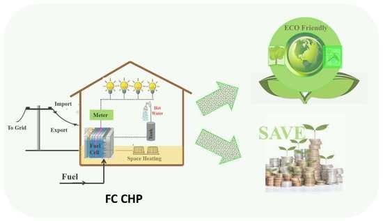
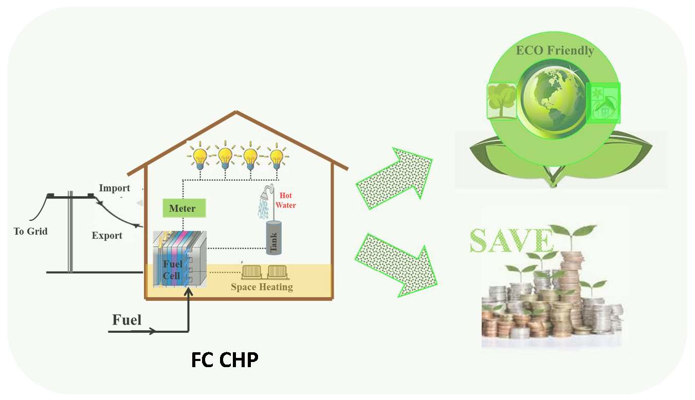
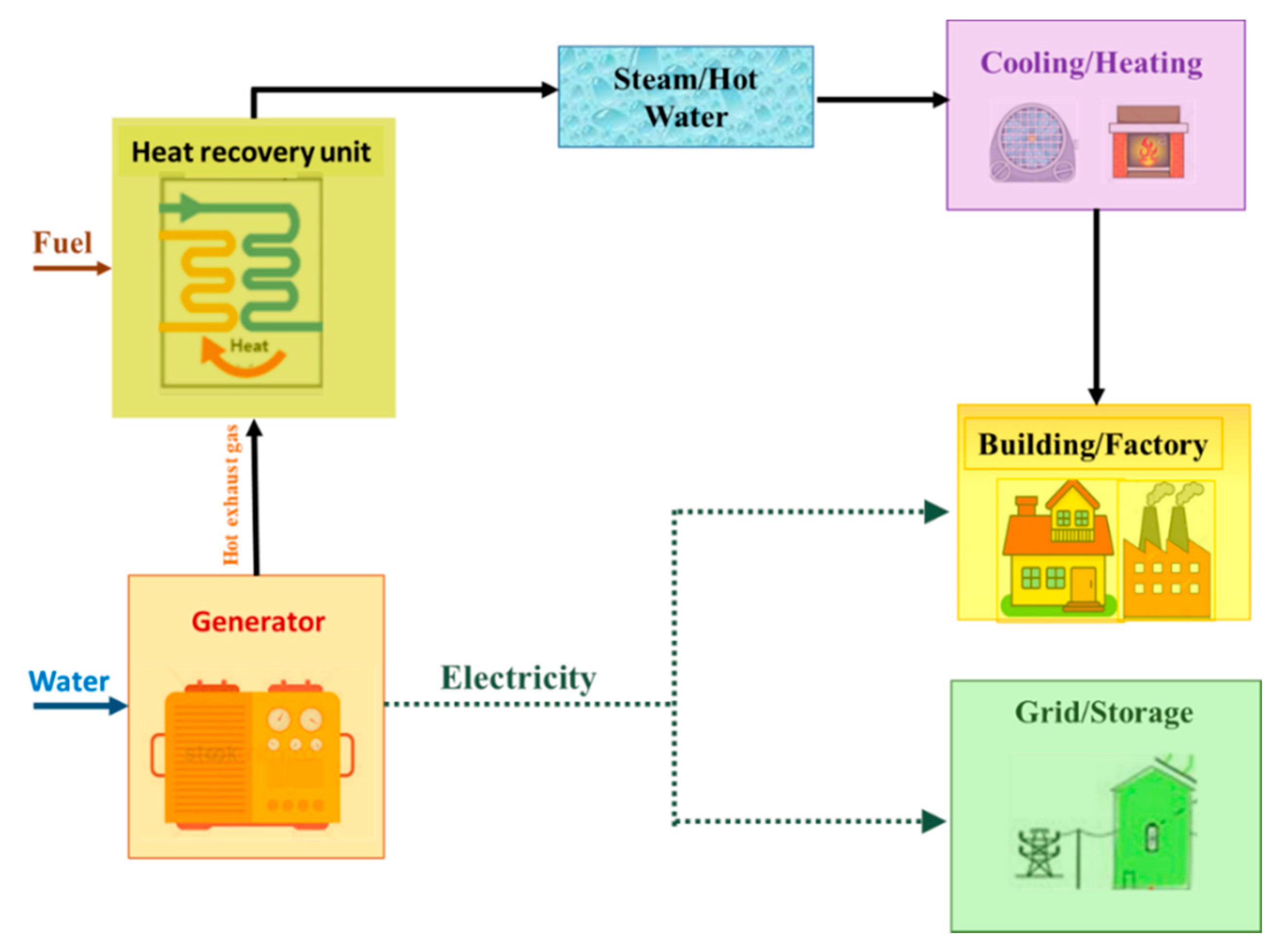
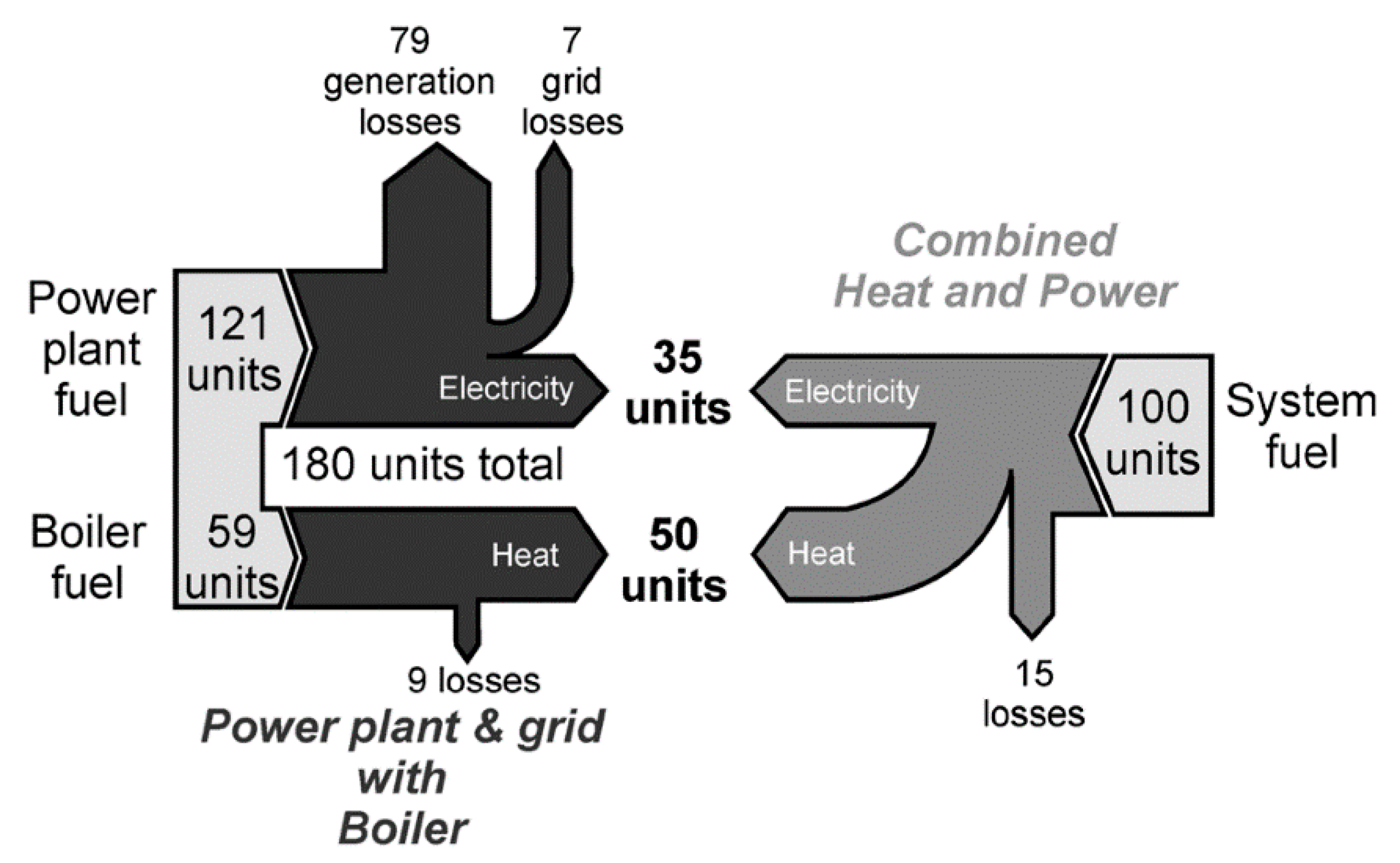
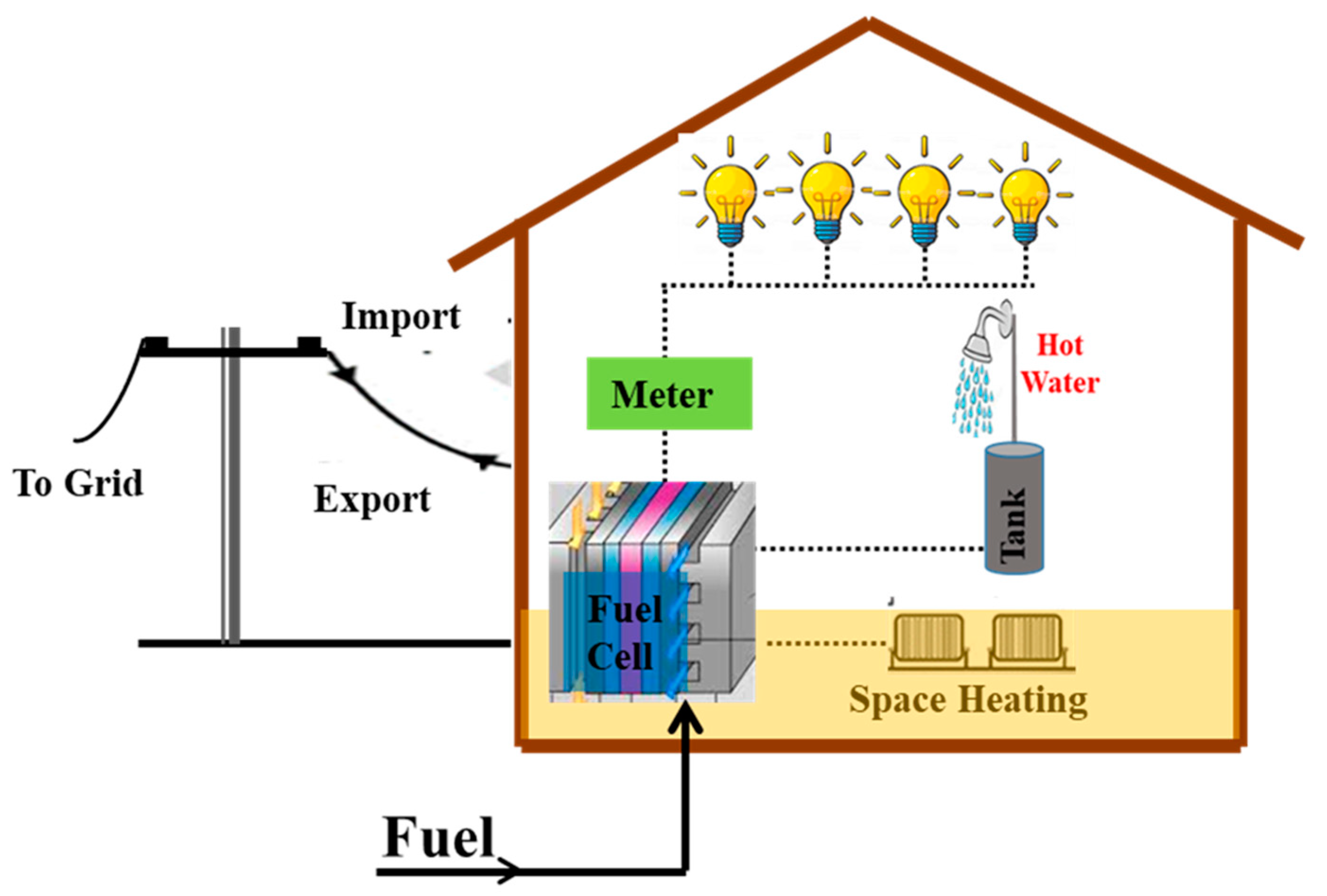
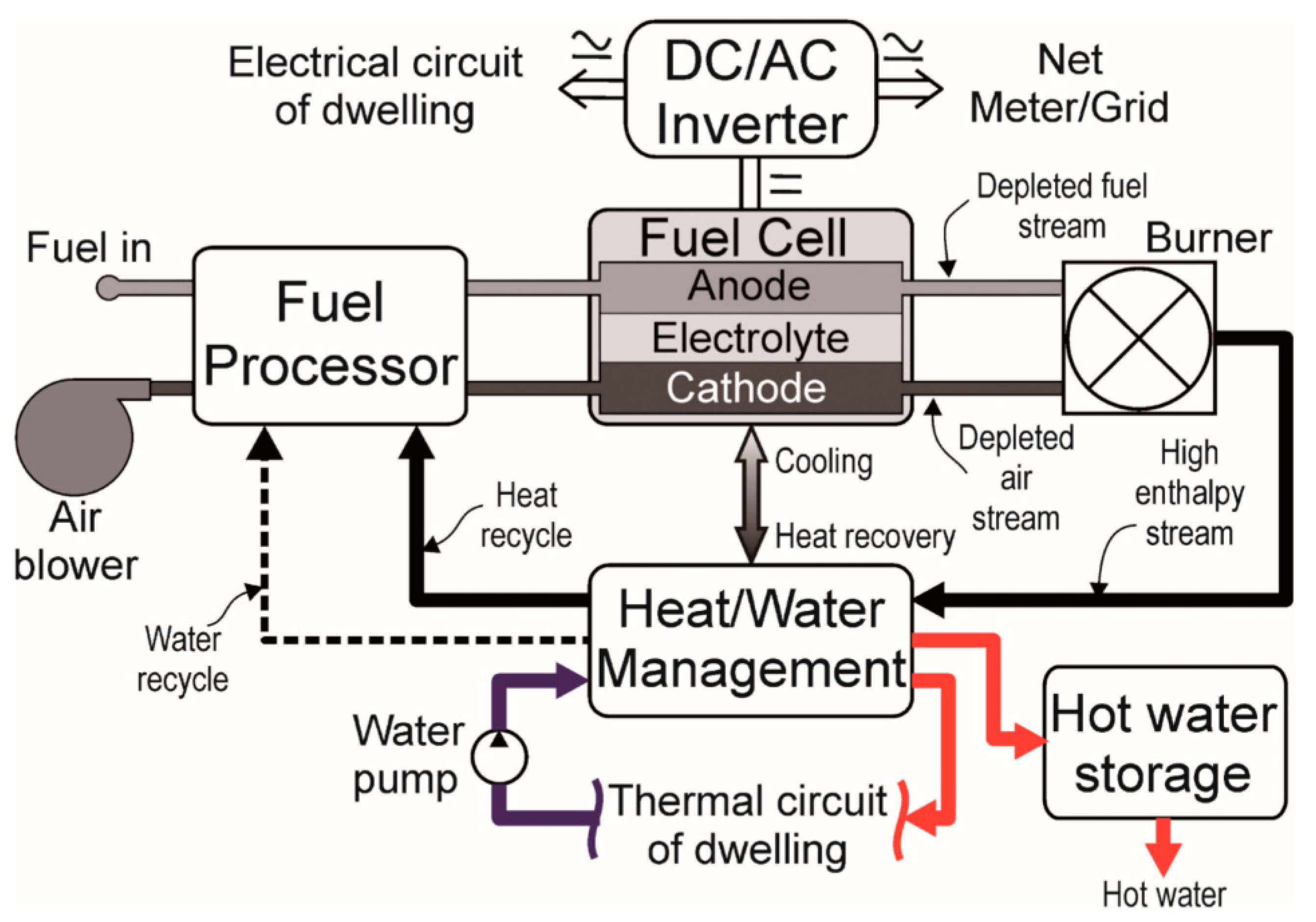
2. Fuel Cell Combined Heat and Power Systems

Fuel cell operates via electrolytic medium purposely for transforming chemical energy of hydrogen, as well as oxygen to power. The byproduct of the electrochemical reaction is water and heat [57,83]. Operating theory resembles that of batteries, but then provides constant energy, from the hydrogen and oxygen supplied to the cell [84]. Fuel cells are able to generate power, releasing no toxic gases into the atmosphere; production of power in fuel cell occurs silently and requires the fuel cell to be frequently disposed of when the fuel is completely utilized [85,86].
Fuel cells could further possibly be utilized in many applications that demand power. Fuel cells could be utilized by substituting the ICEs or batteries in transport applications and portable applications for generating energy. Fuel cells can equally generate power for residential or industrial purposes.
Fuel processor changes the fuel to hydrogen-rich feed streams like natural gas or methanol. The stack then produces electricity, as well as thermal energy, once the hydrogen gas is supplied to it. The power required by the end-user is obtained using the power conditioning system in the form of non-linear DC voltage. Combined heat and power systems are usually made up of a generator, as well as a heat recovery module, as shown in Figure 1, adapted from Reference [29].
A heat exchanger serving as a heat recovery subsystem absorbs the waste heat. The energy that is retained can then be used for heating. Electricity is produced as a result of the generator transforming the chemical energy in the fuel. It is possible to classify cogeneration systems for domestic and industrial institutional applications per their prime mover. Combined heat and power technologies subject to the Stirling engines, as well as fuel cells, are considered to be ideal for cogeneration, especially for household infrastructure. That of the fuel cells is perceived by the research community to have higher efficiency coupled with lower emission levels. Still, presently the cost for internal combustion engines are cheaper compared to the others. Similarly, internal combustion engines can be suitable for combined heat and power systems because they are naturally robust, as well as considered advanced technologies. The microturbine based technologies are ideal for domestic applications [30].
One of the main issues associated with the development of combined heat and power is the challenge relating to the distribution of thermal energy for a longer distance. Due to this, the combined heat and power system must be built near where it is required, and this becomes an extra cost to the system. The fuel cells combined heat and power system have become active research directions because they produce high efficiency for many types of load profiles, as well as low emissions in the absence of any controls. Fuel cells combined heat and power systems achieve greater efficiencies compared to other low-scale power range combined heat and power technologies, which are typical for household uses.
Similarly, for household and industrial areas requiring lower energy (generally less than 10 kW), fuel cell combined heat and power can be used as well. The types of fuel cell combined heat and power based on their power range is captured in Table 1. The heat quality is subject to the fuel cell type used in the system, which directly affects the operating temperatures.
Phosphoric acid fuel cells’ electrical output varies from 37% to 42%, and when working in combined heat and power systems can hit approximately 85%. Systemic performance can surge up to 90%, provided the system makes use of the thermal output. As stand-alone power plant, molten carbonate fuel cell can achieve approximately 47% electrical output, and therefore, can achieve an output of 85% in combined heat and power mode.
The 45% electrical output goal is likely to be attainable with high-temperature PEMFC and solid oxide fuel cells (SOFCs), but low-temperature cells may not be able to attain these efficiencies. Only SOFC systems at required electrical efficiency can achieve targeted combined heat and power efficiency of 90%.
It can be deduced from Table 1 that PEMFCs, as well as SOFCs, are the ideal and often utilized fuel cell systems for domestic purposes. Estimated 138,000 fuel cells combined heat and power systems under 1 kW was developed in Japan by 2014 [87]. Many of the developed combined heat and power systems are based on PEMFCs (85%), and remaining systems are based on SOFCs [88].
Elcore and PlugPower are focusing on designing, as well as demonstrating, high temperature combined heat and power systems. Fuel cells have undergone massive development and demonstration in the last five decades; however, fuel cell systems are still immature. The cost of implementing fuel cell combined heat and power systems are also very high, hence impeding their commercialization [89].

3. Technological Advancement for a Combined Heat and Power System

Fuel cells are starting to gain significant market share, and in the last decade, have switched from the research laboratories to the industrial showroom. Table 2 displays commercially available fuel cell micro (m) combined heat and power devices available on the market. The combined heat and power systems market keeps increasing appreciable over the last couple of years, but there is a huge difference between existing technologies, and these combined heat and power systems [90].
As depicted in Figure 2, the fuel cell combined heat and power systems keep increasing appreciably worldwide, and these values have increased twice-yearly [91]. For instance, the fuel cell commercial shipments increased to 45,700 units as of 2012 [92]. It has been deduced that since 2013, the global market sales for fuel cell combined heat, as well as storage, always exceeded the internal combustion engine system in terms of purchasing capacity. Japan continues to dominate the market share for global fuel cell combined heat and power systems [93]. The Japanese government is nearly meeting its targets in terms of installing 1.4 million fuel cell systems. The basic goal laid down by the South Korean government is to establish a 1 million fuel cell systems, and that of the European Union is 50,000 fuel cells installed.

3.1. Technical Evaluation of Microgeneration and Combined Heat and Power

The production of zero or low carbon heat by small businesses, individuals, and the community, which will supply their own demand is microgeneration. The local generation, for example, can reduce the cost of operation, as well as carbon savings, through the application of renewable energy sources or the retrieval of waste heat, as seen in combined heat and power systems. It curbs the losses relating to producing power through the grid for longer distances. The heat, coupled with power produced, are usually utilized on the spot. Fuel poverty can equally be restrained via lower operating cost, and add to the supply of energy. There are different types of microgeneration that can use the energy already in existence in the environment or produce power, as well as heat from the fuel. The importance of micro combined heat and power in terms of energy-saving is summarized in Figure 3.
A two Sankey diagrams capturing the benefits associated with micro-combined heat and power systems are captured in Figure 3. The diagram compares the delivery and losses of energy for a house with the aid of micro combined heat power systems instead of relying on thermal power plants. Losses via waste heat liberated and losses relating to the transmission of electricity over a longer distance supports the conventional generation scenario. The distance between the load and the generator determines the transmission losses. There are other factors like the voltage used, as well as the number of voltage transformation stages. The losses vary from 6.1% in Germany to 24.2% in Croatia, and 3% to 13% in the United States [95]. The highest efficiency gas subject to heating is provided by the condensing boiler. Some producers of these boilers suggest their efficiency to be nearly 98%. It has been reported that a seasonal efficiency of 91.5% higher heating value was recorded, while 5% efficiency was recorded from an independent study [96]. Figure 4 (adapted from Reference [94]) shows micro combine heat and power system for domestic application.
The gas distribution network from Figure 4 supports the transmission of natural gas. The fuel cell, on the other hand, generates heat for space, as well as water heating coupled with electricity for the light and other appliances. The electricity is sometimes exported to the grid when it is produced in excess and imported as well when demand is high. A storage tank for hot water is also used for storing excess heat. It is equally possible for them to be operated in places where there no electric grid or even a network for distributing natural gas. In an instance like that battery storage is needed. During situations like this, battery storage is required, and the fuel will be supplied in cylinders. European Union cogeneration directive explains micro combine heat and power systems as being made up of below 50 kW. Other authors similarly restricted these values to 15 kWe, and this is ideal for single-family houses and small business.
The Carbon Trust initiated its micro-combined heat and power accelerator program by explaining that micro combine heat and power systems are between 0–3 kWe. To be in conformity to the European Union directive, domestic has been added as a prefix. Microgeneration technologies are caped to 16 A/phase when not connected to relays utilized for domestic purposes in the United Kingdom. Hence applications more than approximately 3.7 kWe need 3—phase G59 relay. This is likely to increase the cost of installation, and line rental [97].
These types of technologies are not suitable for district heating. This is because district heating demands the presence of heat distribution networks that his not available in single-family homes. There are some limitations created on the units running hours when the thermal output is more than the typical requirement for a single house. Combined heat and power at a larger scale in terms of an economic case is very common, especially for schools, hospitals, industry etc. This industrial sector is considered to be advanced. The challenge occurs when considering the same system for residential purposes. The installation of micro combined heat and power is likely to decrease overall emissions by 15–20%. According to Carbon trust, these values were marginal for some micro combine heat and power systems [96].
Figure 5 above depicts a generic fuel cell system for domestic micro combined heat and power systems. The next section will explore the composition of the various elements in the system.

3.1.1. Fuel Cell Stack

Fuel cell stack is the costliest part of the system. It is made up of cells connected in series. The cell stack is made up of an anodic and cathodic electrode with an electrolyte serving as a barrier between the electrode. Bipolar plates support the dissemination of the reactants to the electrodes [98]. The proton exchange membrane fuel cells normally have cooling plates for demineralized water, but the SOFCs depends on air, reducing the cell operating temperature. Precious metal electrocatalysts are needed in PEMFCs to speed up chemical reactions for higher cell efficiency. This often requires graphite powders and resins being used. Other researchers have equally explored the application of membranes that are fluorinated. To ensure the higher performance of the cell, the purity of the hydrogen fuel must be very high because the electrocatalyst can become contaminated by carbon monoxide, as well as other impurities [99]. Humidification of the polymer electrolyte demands complex and expensive engineering solutions.
Recent investigations are aimed at increasing the operating temperature beyond 100 °C [100]. Solid oxide fuel cells utilize ceramics to support their higher cell operating conditions [101]. For micro combined heat and power systems, there is currently an effort to go from the high-temperature region (850–1000 °C) to intermediate temperatures range between 500–750 [102]. It accounts for a wider variety of materials that can be utilized, allowing inexpensive processing and enhanced resilience between ambient and operating temperatures for cycling ceramic components. Operating the cell at lower conditions equally supports the cell to be able to start operation very fast. The rate of corrosion of the metallic part in the cell is also reduced [102]. Pressuring the reactants is likely to enhance the performance of the fuel.

3.1.2. Fuel Processor

In terms of electrochemical efficiency and longevity, hydrogen is a suitable fuel for all types of fuel cells. Similarly, due to lack of supply infrastructure, as well as difficulty in its storage, natural gas is considered as excellent fuel for combined heat and power systems. Methane gas is inexpensive and readily available, hence its patronage. Fuel processors are designed to transform the methane gas, for instance, to hydrogen with low contaminants.
The key distinction between PEMFC and SOFC systems is in the fuel processor design; while the PEMFCs need higher purity fuel, the solid oxide is able to reform hydrocarbon fuels internally. Typically, a solid oxide fuel processor consists of a desulfurizer, and a pre-reformer. SOFCs ability to operate on hydrocarbon fuels at high efficiency is a massive benefit over low-temperature fuel cells [103].
Natural gas is capable of being transformed into hydrogen through a variety of methods. Steam reforming is usually recommended as it generates better hydrogen concentrations [104]. The hydrogen-rich stream that leaves the reformer will be made up of carbon monoxide, as well as sulfur compounds. Both molecules are toxic to PEMFCs, although SOFCs are capable of using carbon monoxide as a fuel. Therefore, sulfur compounds should be eliminated, typically by reacting with zinc oxide. The unit will have to be regularly checked. This, therefore, becomes an extra cost to the system maintenance costs.
Other methods of desulfurization are available. The majority of these techniques are not appropriate for usage in some applications on a small scale [105]. For proton exchange membrane fuel cells, to avoid poisoning the platinum-based anode electrocatalyst, the level of carbon monoxide accessing the fuel cell must be reduced to the order of less than 100 ppm. Carbon monoxide generated during the process of steam reforming can subsequently be transformed into carbon dioxide in a shift reactor.
Methods, such as selective carbon monoxide oxidation, could be utilized to decrease the concentration of carbon monoxide to safe proton exchange membrane levels [106]. Consequently, the fuel processor for a proton exchange membrane fuel cell is quite complex and needs good temperature control. Above all, the turndown ratio is mostly affected since maintenance of thermal homogeneity remains a considerable problem. Solid oxide fuel cell systems have a strong benefit over proton exchange membrane fuel cell systems, as they are able to change hydrocarbons entirely internally.

3.1.3. Inverter/Power Electronics

For a 1 kWe system, the voltage generated by the stack is low. There is also high direct current (DC) output, usually more than 15 V to a maximum of 40 V. Therefore, it requires an inverter to transform this into alternating current appropriate for other devices, as well as being sold to the grid. The inverter performance is normally between 85–95% at the sub-10 kW level [107].

3.1.4. Water Management

Steam reforming, as well as ensuring proper water management in the cell, will require high purity water to support the conduction of the protons. Heat exchanger removes water from stack exit, harvest heat, and provide process water, which can be utilized for steam reforming or for proton exchange membrane fuel cell water management.

3.1.5. Heat Management

Efficient heat retrieval is crucial for a micro-combined heat and power system’s environmental and economic performance. There is significantly different heat separation from the PEMFCs, as well as that from the solid oxide systems. Heat is normally derived from the circulating cooling liquid for the PEMFCs, which moves via the cooling plates. This leaves the stack at 80 °C approximately, an optimal temperature for heating up room and hot water.
Coolant for the stack is the cathode air flow for SOFCs and requires a heavily over-stochiometric amount of air. The air and unconsumed fuel end up leaving the stack at its operating temperature, as well as heated up in the afterburner. Given that exhaust stream temperature is more than that of proton exchange membrane fuel cells cooling circuit (around 80 °C), transfer of heat to the dwelling’s thermal circuit is much more efficient. It is worth noting that both an afterburner and an abstract higher temperature heat from unused fuel exiting the fuel cell may also be used by the proton exchange membrane fuel cell.

3.1.6. System for Delivering the Reactants

As all micro combined heat and power systems are not pressurized, blower instead of the compressor is utilized to deliver air to the machine. The mains gas pressure entering a home, and of course the tanked storage pressure, is necessary to supply a micro-CHP system. The high-temperature operation of solid oxide fuel cells implies preheating of the fuel, as well as air approaching the stack to a degree, which prevents thermal shock to the stack’s ceramic portion. Fuel cell producing no noise during its operation is considered as an advantage.

3.1.7. Afterburner/Auxiliary Burner

Heat energy could be produced with the aid of an auxiliary burner via the burning of unreacted fuel. It is a choice for adjusting the system’s heat-to-power ratio. At the maximum, the stack can be fully bypassed. This would imply an over-sizing burner as opposed to regular combined heat and power operation, increasing the cost. For PEMFC, adequate heat is needed for serving the fuel processor’s endothermic reforming level. Likewise (or moreover) CH4 could be directly combusted to serve the reformer [108]. In the worst-case scenario, the stack of fuel cells can be completely avoided. For PEMFCs, sufficient heat is needed to serve the fuel processor’s endothermal reforming level, so the stack must operate with a fuel usage of no more than approximately 70% to burn the unused hydrogen and serve the reformer.

3.2. Summary of Merits of Fuel Cell Combined Heat and Power Systems

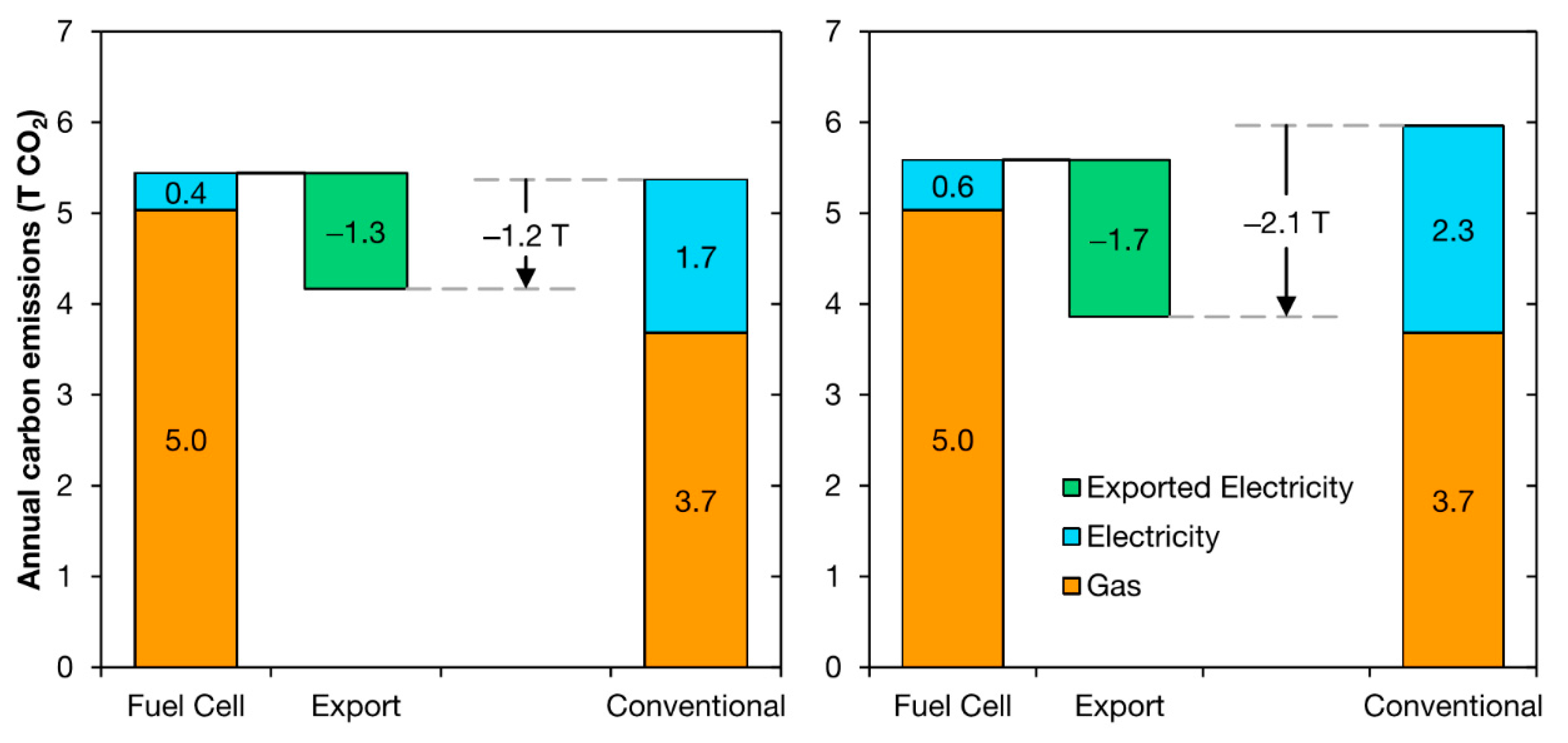
3.2.1. Carbon Dioxide Emission Reduction

Global total carbon dioxide emissions in 2018 increased by 1.7%, which is 33.1 Gt carbon dioxide. This was as a result of the increasing power demand largely generated from fossil commodities. The emissions from this sector are anticipated to continue to rise to 37 Gt in 2035 [109]. A substantial share of greenhouse gas toxic gaseous release increased as a result of higher demand for coal [110]. The growth and development of combined heat and power systems could decrease carbon dioxide release into the atmosphere from the new generation by more than 4% (170 Mt/year), although the saving may boost to more than 10% (950 Mt/year) in 2030 [111]. Therefore, combined heat and power systems can make a significant contribution to achieving emission stabilization, which is needed to avoid major climate disruption. Crucially, combined heat and power near-term emission cuts are achievable, and hence, can provide major chances for low cost greenhouse gas emission decrement [112]. Yearly carbon dioxide emissions reductions are hard to determine.
It is anticipated that residential fuel cell combined heat and power systems of about 1 kW will decrease domestic gaseous release into the atmosphere by 1.3–1.9 tons of carbon dioxide yearly in Japan and Germany. Fuel cells combined heat and power producer CFCL reports to save around 3tonnes per year because of its larger capacity on its BlueGen [112]. A fuel cell and micro combined heat and power systems having an electrical output of 1 kW can produce daily savings estimated at 4.5+ kg carbon dioxide in winter, and 3+ kg carbon dioxide in the summer. The total carbon emissions annually subject to the performance of PEMFCs in UK home has been compared to traditional heating systems as captured in Figure 6 [113]. It was, however, deduced that for a country that relies on coal-fired power, the yearly carbon savings from the fuel cell is likely to be higher [114,115,116]. Residential proton exchange membrane fuel cells produce 553 g of carbon dioxide to generate 1 kWh of power and 1.4 kWh of heat [116]. The fuel processor is the source for the emission of carbon dioxide. The fuel processor splits the hydrocarbon fuel to hydrogen gas, carbon dioxide, as well as other impurities, with few amounts of fuel being produced for the generation of heat required for reforming.

3.2.2. Carbon Footprint for Construction

A fuel cell’s ‘carbon footprint’ or ‘embodied carbon’ is a measure of the greenhouse gas emissions which its development causes. Various assessments approximated these toxic gaseous release by taking into account the manufacturing of the fuel cell, the quantity of material used, as well as the production process of the materials. The production of metals, such as nickel and platinum, requires lots of energy. The generation of 1 kW of power for domestic purposes using fuel cell combined heat and power will also lead to the production of 0.5–1 tons of carbon dioxide emissions. On the other hand, 100 kW commercial system leads to 25–100 tons being emitted [117,118,119]. The toxic gaseous release from manufacturing the cell can be ‘levelized’ by averaging. The development of domestic proton exchange membrane fuel cells, as well as solid oxide fuel cells, results in the gaseous release of 10–20 g of carbon dioxide for every kW generated [118,119,120,121].

3.2.3. Decrease in Pollutant

Combustion of fossil fuel usually leads to the emission of many toxic substances into the atmosphere, such as nitrogen oxides (NOx), as well as sulfur dioxide (SO2). Sulfur dioxide emissions are from the production of energy, and this, according to literature, contributes to more than 40% of the total emissions gathered annually [122]. Sulfur dioxide emissions are usually associated with the combustion of coal and diesel fuel, but nitrous oxide pollutants are generated from the combustion of different types of fuels.
These types of emissions tend to have a detrimental effect on the environment like causing acid rain. In terms of power generating methods for the fuel cell, the amount of gaseous toxic substances produced in the fuel cell are few. For combined heat and power systems, pollutions due to the presence of nitrous oxide is few compared to that of coal-fired electricity production mediums. Nitrous gas emissions from diesel engines are usually between 1.27–15 kg MWh−1. For natural gas, nitrous gas emissions are between 1–12.7 kg MWh−1. Microturbine engines, on the other hand, also generate 0.18–1 kg MWh−1, as well as for fuel cell combined heat and power; they are lower than 0.01 kg MWh−1 [122,123]. Emissions of nitrous oxide source from fuel cell combined heat and power is simply a burner responsible for the supply of thermal energy mainly for endothermic reaction to occur due to the burning of the gas. Various types of burner development have been explored to limit the total gaseous toxic substances generated. There is also the possibility for methane emissions due to incomplete burning or leakage, as well as losses due to gas transport. The emission of sulfur dioxide, as well as mercury compounds from the combustion of natural gas, can be neglected. Sulfur dioxide emissions are removed during the operation of fuel cell combined heat and power [124,125,126].
The average industrial level for airborne pollutants like nitrous oxide, carbon mono oxide, as well as particulates from the fuel cells, boilers, and combined heat power engines, are summarized in Table 3. Measuring the emissions from fuel cells are always lower compared to other combustion technologies, hence their huge recommendation by the research community.

3.2.4. Reduction of Electricity Cost

The owner of the household having the micro combined heat and power system, enjoys lots of benefits compared to large energy suppliers. The cost in generating the electricity cost related to subsidies for energy technologies, electrical transmission, as well as the distribution cost through the grid network coupled with the final retail customer all determines the cost of the electricity being generated for the end-user. The cost of electricity in Europe varies between £0.087–0. 298 per kWh for households having their consumption between 2500–5000 kWh [127]. The economic value for the energy generated from fuel cell combined heat and power systems tend to have higher economic value. This is 3–3.5 times more compared to power plants powered using natural gas. Fuel cell combined heat and power transforms lower cost of fuel. This helps in reducing the bills in most households. The efficiency of the power produced in the power plant is between 35–37%. Combine the efficiency of nearly 45% is recorded for centralized power generation. Cogeneration systems can attain performance levels of 80%. Distribution, coupled with the transmission of electricity from the central power stations, add an extra loss of 9%. It implies that the end-user gets one—third of the power supplied. Distribution, as well as transmission losses, therefore, varies subject to distances. From the world data, transmitting electricity and losses associated with distributing the power varies between 1.82–54.60%, with an average of 8.10% [128].

3.2.5. Grid Independence

There has been an appreciable increase in the market potential for fuel cell systems, hence recommended widely by scientists as suitable for solving grid outages. From the United states statistics, 80–90% of energy fiasco comes during the process of distributing the power [129]. The cost associated with these electricity failures is projected to $119 billion annually. More than 45, 000 end-users are affected during these power outages [130]. Failure is associated with some computers, as well as electronic devices, in power fluctuations contributes to power outages. The prices of the yearly cost of power failure linked small industrial structure is summed up in Table 4 [130]. Price for these power cuts varies between $4000–6800 USD.

4. Challenges Associated to Fuel Cell Combined Heat and Power Systems

The main challenge associated with fuel cell combined heat and power system is the high initial capital required for the development of the project, compared with competing with other existing combined heat and power generation technologies. The selection of combined heat and power technology is associated with the cost of generation and system availability. The number of combined heat power units sold is low, but most fuel cell systems for portable applications enjoy huge government subsidies, hence their patronage compared to other combined heat and power systems [131]. The original price for fuel cell combined micro heat and power system is nearly 30–50 times more than the targets laid down by the United States Department of Energy. The cost of 1 kW PEMFCs or SOFCs in Japan was between $21,000–27000 USD.
The cost of the residential system has declined massively in the last decade. In Japan, government subsidy forms nearly 50% of the price for installing the unit. The cost of the system can decrease significantly with respect to time, but this is subject to the economies of scale provided due to producing them in larger quantities. Figure 7 summarizes the cost in terms of reduction for proton exchange membrane fuel cells in Japan and South Korea.

5. Conclusions

Micro-CHP systems are appealing, high-efficiency technologies for decentralized electric power generation. This investigation explores and focuses on micro fuel cell combined heat and power systems. Fuel cell combined heat and power has become the most beneficial and effective cogeneration technology. The system has many strengths that can overcome current power generation problems, but it comes with some challenges.
The main drawback at the moment is the initial capital cost, which is expensive. In several demonstration projects, the Japanese scenario demonstrates that it is imperative to reduce the price of fuel cell combined heat and power systems by approximately 25% by doubling the output, and a further 13% reduction after commercialization can be obtained. Several countries are formulating policies, for example, through the implementation of subsidies, which encourage and enhance the applications of fuel cells combined heat and power systems.
Most research activities are geared towards the goals of manufacturing thousands (1000′s) of fuel cell combined heat and power systems worldwide for development and deployment. From techno-economic evaluation and energy needs, the appropriate and directed market for fuel cell combined heat and power systems is for domestic purposes, where units up to 1 kWel of power may be utilized for electric power and heat production.
These two fuel cell systems (PEMFCs and SOFCs) are at the moment being used for residential applications in fuel cell combined heat and power systems. SOFCs offer high-quality, high-temperature heat operation. The main issues associated with SOFCs have to do with the time it takes for it to start. Low-temperature PEMFC-oriented cogeneration systems exhibit quite high efficiencies and reliability. The low-temperature PEMFC high power density is undoubtedly the biggest benefit; however, one of the key challenges is the complicated water management. It is imperative that future research work keenly considered novel systemic designs that will make the entire unit very robust in terms of size and weight to reduce the cost of the system. Material characterization and optimization of the fuel cell will significantly reduce the initial capital cost required for establishing such projects. Furthermore, to foster healthy competition with existing technologies, a well-documented risk assessment strategy for the individual components and the entire system, coupled with effective public sensitization about the validity of the technology should be an active research direction.

Author Contributions

Conceptualization, T.W., M.A.A., E.T.S., A.G.O., and K.E.; methodology, T.W. and M.A.A.; formal analysis, T.W., M.A.A.; investigation, E.T.S., A.G.O., K.E., T.W.; resources, T.W., E.T.S.; data curation, K.E., M.A.A., T.W., A.G.O.; writing—original draft preparation, E.T.S., T.W., M.A.A.; writing—review and editing, T.W., M.A.A., K.E., A.G.O.; supervision, A.G.O., M.A.A.; project administration, T.W.; All authors have read and agreed to the published version of the manuscript.

Funding

This research received no external funding.

Conflicts of Interest

The authors declare no conflict of interest.

References

  1. Elsaid, K.; Sayed, E.T.; Abdelkareem, M.A.; Baroutaji, A.; Olabi, A.G. Environmental impact of desalination processes: Mitigation and control strategies. Sci. Total Environ. 2020, 740, 140125. [Google Scholar] [CrossRef]
  2. Elsaid, K.; Sayed, E.T.; Abdelkareem, M.A.; Mahmoud, M.S.; Ramadan, M.; Olabi, A.G. Environmental impact of emerging desalination technologies: A preliminary evaluation. J. Environ. Chem. Eng. 2020, 8, 104099. [Google Scholar] [CrossRef]
  3. Wilberforce, T.; Baroutaji, A.; Soudan, B.; Al-Alami, A.H.; Olabi, A.G. Outlook of carbon capture technology and challenges. Sci. Total Environ. 2019, 657, 56–72. [Google Scholar] [CrossRef] [PubMed] [Green Version]
  4. Singh, D.; Sharma, D.; Soni, S.; Sharma, S.; Sharma, P.K.; Jhalani, A. A review on feedstocks, production processes, and yield for different generations of biodiesel. Fuel 2020, 262, 116553. [Google Scholar] [CrossRef]
  5. Vakulchuk, R.; Overland, I.; Scholten, D. Renewable energy and geopolitics: A review. Renew. Sustain. Energy Rev. 2020, 122, 109547. [Google Scholar] [CrossRef]
  6. Seruga, P.; Krzywonos, M.; Seruga, A.; Niedźwiecki, Ł.; Pawlak-Kruczek, H.; Urbanowska, A. Anaerobic digestion performance: Separate collected vs. mechanical segregated organic fractions of municipal solid waste as feedstock. Energies 2020, 13, 3768. [Google Scholar] [CrossRef]
  7. Elsaid, K.; Taha Sayed, E.; Yousef, B.A.A.; Kamal Hussien Rabaia, M.; Ali Abdelkareem, M.; Olabi, A.G. Recent progress on the utilization of waste heat for desalination: A review. Energy Convers. Manag. 2020, 221, 113105. [Google Scholar] [CrossRef]
  8. Olabi, A.G.; Elsaid, K.; Rabaia, M.K.H.; Askalany, A.A.; Abdelkareem, M.A. Waste heat-driven desalination systems: Perspective. Energy 2020, 118373, in press. [Google Scholar] [CrossRef]
  9. Jouhara, H.; Olabi, A.G. Editorial: Industrial waste heat recovery. Energy 2018, 160, 1–2. [Google Scholar] [CrossRef]
  10. Yousef, B.A.A.; Rezk, H.; Abdelkareem, M.A.; Olabi, A.G.; Nassef, A.M. Fuzzy modeling and particle swarm optimization for determining the optimal operating parameters to enhance the bio-methanol production from sugar cane bagasse. Int. J. Energy Res. 2020. [Google Scholar] [CrossRef]
  11. Rezk, H.; Alsaman, A.S.; Al-Dhaifallah, M.; Askalany, A.A.; Abdelkareem, M.A.; Nassef, A.M. Identifying optimal operating conditions of solar-driven silica gel based adsorption desalination cooling system via modern optimization. Sol. Energy 2019, 181, 475–489. [Google Scholar] [CrossRef]
  12. Rezk, H.; Sayed, E.T.; Al-Dhaifallah, M.; Obaid, M.; El-Sayed, A.H.M.; Abdelkareem, M.A.; Olabi, A.G. Fuel cell as an effective energy storage in reverse osmosis desalination plant powered by photovoltaic system. Energy 2019, 175, 423–433. [Google Scholar] [CrossRef] [Green Version]
  13. Fathy, A.; Elaziz, M.A.; Sayed, E.T.; Olabi, A.G.; Rezk, H. Optimal parameter identification of triple-junction photovoltaic panel based on enhanced moth search algorithm. Energy 2019, 188, 116025. [Google Scholar] [CrossRef]
  14. Soudan, B. Community-scale baseload generation from marine energy. Energy 2019, 189, 116134. [Google Scholar] [CrossRef]
  15. Wilberforce, T.; El Hassan, Z.; Durrant, A.; Thompson, J.; Soudan, B.; Olabi, A.G. Overview of ocean power technology. Energy 2019, 175, 165–181. [Google Scholar] [CrossRef] [Green Version]
  16. Sayed, E.T.; Shehata, N.; Abdelkareem, M.A.; Atieh, M.A. Recent progress in environmentally friendly bio-electrochemical devices for simultaneous water desalination and wastewater treatment. Sci. Total Environ. 2020, 141046, in press. [Google Scholar] [CrossRef]
  17. Inayat, A.; Nassef, A.M.; Rezk, H.; Sayed, E.T.; Abdelkareem, M.A.; Olabi, A.G. Fuzzy modeling and parameters optimization for the enhancement of biodiesel production from waste frying oil over montmorillonite clay K-30. Sci. Total Environ. 2019, 666, 821–827. [Google Scholar] [CrossRef] [PubMed] [Green Version]
  18. Mahmoud, M.; Ramadan, M.; Olabi, A.-G.; Pullen, K.; Naher, S. A review of mechanical energy storage systems combined with wind and solar applications. Energy Convers. Manag. 2020, 210, 112670. [Google Scholar] [CrossRef]
  19. Mohamed, M.A.; Diab, A.A.Z.; Rezk, H.; Jin, T. A novel adaptive model predictive controller for load frequency control of power systems integrated with DFIG wind turbines. Neural Comput. Appl. 2020, 32, 7171–7181. [Google Scholar] [CrossRef]
  20. Abdelkareem, M.A.; El Haj Assad, M.; Sayed, E.T.; Soudan, B. Recent progress in the use of renewable energy sources to power water desalination plants. Desalination 2018, 435, 97–113. [Google Scholar] [CrossRef]
  21. Wilberforce, T.; Baroutaji, A.; El Hassan, Z.; Thompson, J.; Soudan, B.; Olabi, A.G. Prospects and challenges of concentrated solar photovoltaics and enhanced geothermal energy technologies. Sci. Total Environ. 2019, 659, 851–861. [Google Scholar] [CrossRef] [PubMed] [Green Version]
  22. Shabani, B.; Andrews, J. Standalone solar-hydrogen systems powering fire contingency networks. Int. J. Hydrog. Energy 2015, 40, 5509–5517. [Google Scholar] [CrossRef]
  23. Yilanci, A.; Dincer, I.; Ozturk, H.K. A review on solar-hydrogen/fuel cell hybrid energy systems for stationary applications. Prog. Energy Combust. Sci. 2009, 35, 231–244. [Google Scholar] [CrossRef]
  24. Maniatopoulos, P.; Andrews, J.; Shabani, B. Towards a sustainable strategy for road transportation in Australia: The potential contribution of hydrogen. Renew. Sustain. Energy Rev. 2015, 52, 24–34. [Google Scholar] [CrossRef]
  25. Kharel, S.; Shabani, B. Hydrogen as a long-term large-scale energy storage solution to support renewables. Energies 2018, 11, 2825. [Google Scholar] [CrossRef] [Green Version]
  26. Brandon, N.; Kurban, Z. Clean energy and the hydrogen economy. Philos. Trans. R. Soc. A Math. Phys. Eng. Sci. 2017, 375, 20160400. [Google Scholar] [CrossRef] [PubMed]
  27. Andrews, J.; Shabani, B. The role of hydrogen in a global sustainable energy strategy. Wiley Interdiscip. Rev. Energy Environ. 2014, 3, 474–489. [Google Scholar] [CrossRef]
  28. Elmer, T.; Worall, M.; Wu, S.; Riffat, S.B. Fuel cell technology for domestic built environment applications: State of-the-art review. Renew. Sustain. Energy Rev. 2015, 42, 913–931. [Google Scholar] [CrossRef]
  29. Ellamla, H.R.; Staffell, I.; Bujlo, P.; Pollet, B.G.; Pasupathi, S. Current status of fuel cell based combined heat and power systems for residential sector. J. Power Sources 2015, 293, 312–328. [Google Scholar] [CrossRef]
  30. Onovwiona, H.; Ugursal, V.I. Residential cogeneration systems: Review of the current technology. Renew. Sustain. Energy Rev. 2006, 10, 389–431. [Google Scholar] [CrossRef]
  31. Wilberforce, T.; El-Hassan, Z.; Khatib, F.; Al Makky, A.; Mooney, J.; Barouaji, A.; Carton, J.G.; Olabi, A.-G. Development of Bi-polar plate design of PEM fuel cell using CFD techniques. Int. J. Hydrog. Energy 2017, 42, 25663–25685. [Google Scholar] [CrossRef] [Green Version]
  32. Wilberforce, T.; Ijaodola, O.; Ogungbemi, E.; Khatib, F.; Leslie, T.; El-Hassan, Z.; Thomposon, J.; Olabi, A. Technical evaluation of proton exchange membrane (PEM) fuel cell performance–A review of the effects of bipolar plates coating. Renew. Sustain. Energy Rev. 2019, 113, 109286. [Google Scholar] [CrossRef]
  33. Wilberforce, T.; El Hassan, Z.; Ogungbemi, E.; Ijaodola, O.; Khatib, F.; Durrant, A.; Thompson, J.; Baroutaji, A.; Olabi, A. A comprehensive study of the effect of bipolar plate (BP) geometry design on the performance of proton exchange membrane (PEM) fuel cells. Renew. Sustain. Energy Rev. 2019, 111, 236–260. [Google Scholar] [CrossRef]
  34. Abdelkareem, M.A.; Sayed, E.T.; Mohamed, H.O.; Obaid, M.; Rezk, H.; Chae, K.-J. Nonprecious anodic catalysts for low-molecular-hydrocarbon fuel cells: Theoretical consideration and current progress. Prog. Energy Combust. Sci. 2020, 77, 100805. [Google Scholar] [CrossRef]
  35. Sayed, E.T.; Eisa, T.; Mohamed, H.O.; Abdelkareem, M.A.; Allagui, A.; Alawadhi, H.; Chae, K.-J. Direct urea fuel cells: Challenges and opportunities. J. Power Sources 2019, 417, 159–175. [Google Scholar] [CrossRef]
  36. Abdelkareem, M.A.; Sayed, E.T.; Alawadhi, H.; Alami, A.H. Synthesis and testing of cobalt leaf-like nanomaterials as an active catalyst for ethanol oxidation. Int. J. Hydrog. Energy 2020, 45, 17311–17319. [Google Scholar] [CrossRef]
  37. Ijaodola, O.; El-Hassan, Z.; Ogungbemi, E.; Khatib, F.; Wilberforce, T.; Thompson, J.; Olabi, A. Energy efficiency improvements by investigating the water flooding management on proton exchange membrane fuel cell (PEMFC). Energy 2019, 179, 246–267. [Google Scholar] [CrossRef]
  38. Abdelkareem, M.A.; Allagui, A.; Sayed, E.T.; El Haj Assad, M.; Said, Z.; Elsaid, K. Comparative analysis of liquid versus vapor-feed passive direct methanol fuel cells. Renew. Energy 2019, 131, 563–584. [Google Scholar] [CrossRef]
  39. Olabi, A.G.; Wilberforce, T.; Sayed, E.T.; Elsaid, K.; Rezk, H.; Abdelkareem, M.A. Recent progress of graphene based nanomaterials in bioelectrochemical systems. Sci. Total Environ. 2020, 141225. [Google Scholar] [CrossRef]
  40. Sayed, E.T.; Abdelkareem, M.A. Yeast as a biocatalyst in microbial fuel cell. Old Yeasts New Quest. Intech 2017, 41–65. [Google Scholar]
  41. Alami, A.H.; Abdelkareem, M.A.; Faraj, M.; Aokal, K.; Al Safarini, N. Titanium dioxide-coated nickel foam photoelectrodes for direct urea fuel cell applications. Energy 2020, 208, 118253. [Google Scholar] [CrossRef]
  42. Fathy, A.; Abdelkareem, M.A.; Olabi, A.G.; Rezk, H. A novel strategy based on salp swarm algorithm for extracting the maximum power of proton exchange membrane fuel cell. Int. J. Hydrog. Energy 2020, in press. [Google Scholar] [CrossRef]
  43. Larminie, J.; Dicks, A.; McDonald, M.S. Fuel Cell Systems Explained; J. Wiley: Chichester, UK, 2003; Volume 2. [Google Scholar]
  44. Wilberforce, T.; Khatib, F.; Ijaodola, O.; Ogungbemi, E.; El-Hassan, Z.; Durrant, A.; Thompson, J.; Olabi, A. Numerical modelling and CFD simulation of a polymer electrolyte membrane (PEM) fuel cell flow channel using an open pore cellular foam material. Sci. Total Environ. 2019, 678, 728–740. [Google Scholar] [CrossRef] [PubMed]
  45. Baroutaji, A.; Wilberforce, T.; Ramadan, M.; Olabi, A.G. Comprehensive investigation on hydrogen and fuel cell technology in the aviation and aerospace sectors. Renew. Sustain. Energy Rev. 2019, 106, 31–40. [Google Scholar] [CrossRef] [Green Version]
  46. Abdelkareem, M.A.; Sayed, E.T.; Nakagawa, N. Significance of diffusion layers on the performance of liquid and vapor feed passive direct methanol fuel cells. Energy 2020, 209, 118492. [Google Scholar] [CrossRef]
  47. Jiao, F.; Xu, B. Electrochemical Ammonia Synthesis and Ammonia Fuel Cells. Adv. Mater. 2019, 31, 1805173. [Google Scholar] [CrossRef]
  48. Boldrin, P.; Brandon, N.P. Progress and outlook for solid oxide fuel cells for transportation applications. Nat. Catal. 2019, 2, 571–577. [Google Scholar] [CrossRef] [Green Version]
  49. Rezk, H.; Nassef, A.M.; Abdelkareem, M.A.; Alami, A.H.; Fathy, A. Comparison among various energy management strategies for reducing hydrogen consumption in a hybrid fuel cell/supercapacitor/battery system. Int. J. Hydrog. Energy 2019, in press. [Google Scholar] [CrossRef]
  50. Ogungbemi, E.; Wilberforce, T.; Ijaodola, O.; Thompson, J.; Olabi, A. Selection of proton exchange membrane fuel cell for transportation. Int. J. Hydrog. Energy 2020, in press. [Google Scholar] [CrossRef]
  51. Mohideen, M.M.; Liu, Y.; Ramakrishna, S. Recent progress of carbon dots and carbon nanotubes applied in oxygen reduction reaction of fuel cell for transportation. Appl. Energy 2020, 257, 114027. [Google Scholar] [CrossRef]
  52. Rath, R.; Kumar, P.; Mohanty, S.; Nayak, S.K. Recent advances, unsolved deficiencies, and future perspectives of hydrogen fuel cells in transportation and portable sectors. Int. J. Energy Res. 2019, 43, 8931–8955. [Google Scholar] [CrossRef]
  53. Zhang, G.; Kandlikar, S.G. A critical review of cooling techniques in proton exchange membrane fuel cell stacks. Int. J. Hydrog. Energy 2012, 37, 2412–2429. [Google Scholar] [CrossRef]
  54. Zaman, S.F.; Jolaoso, L.A.; Podila, S.; Al-Zahrani, A.A.; Alhamed, Y.A.; Driss, H.; Daous, M.M.; Petrov, L. Ammonia decomposition over citric acid chelated g-Mo2N and Ni2Mo3N catalysts. Int. J. Hydrog. Energy 2018, 43, e17258. [Google Scholar] [CrossRef]
  55. Rosli, R.; Sulong, A.; Daud, W.; Zulkifley, M.; Husaini, T.; Rosli, M.; Majlan, E.; Haque, M. A review of high-temperature proton exchange membrane fuel cell (HT-PEMFC) system. Int. J. Hydrog. Energy 2017, 42, 9293–9314. [Google Scholar] [CrossRef]
  56. Wilberforce, T.; Ijaodola, O.; Khatib, F.; Ogungbemi, E.; El Hassan, Z.; Thompson, J.; Olabi, A. Effect of humidification of reactive gases on the performance of a proton exchange membrane fuel cell. Sci. Total Environ. 2019, 688, 1016–1035. [Google Scholar] [CrossRef] [PubMed]
  57. Ijaodola, O.; Ogungbemi, E.; Khatib, F.N.; Wilberforce, T.; Ramadan, M.; El Hassan, Z.; Thompson, J.; Olabi, A.G. Evaluating the effect of metal bipolar plate coating on the performance of proton exchange membrane fuel cells. Energies 2018, 11, 3203. [Google Scholar] [CrossRef] [Green Version]
  58. Wilberforce, T.; Alaswad, A.; Palumbo, A.; Dassisti, M.; Olabi, A.-G. Advances in stationary and portable fuel cell applications. Int. J. Hydrog. Energy 2016, 41, 16509–16522. [Google Scholar] [CrossRef] [Green Version]
  59. Wilberforce, T.; Ijaodola, O.; Ogungbemi, E.; El Hassan, Z.; Thompson, J.; Olabi, A.G. Effect of bipolar plate materials on performance of fuel cells. In Reference Module in Materials Science and Materials Engineering; Elsevier Inc.: Amsterdam, The Netherlands, 2018; pp. 1–15. [Google Scholar]
  60. Islam, M.R.; Shabani, B.; Rosengarten, G. Nanofluids to improve the performance of PEM fuel cell cooling systems: A theoretical approach. Appl. Energy 2016, 178, 660–671. [Google Scholar] [CrossRef]
  61. Islam, M.; Shabani, B.; Rosengarten, G.; Andrews, J. The potential of using nanofluids in PEM fuel cell cooling systems: A review. Renew. Sustain. Energy Rev. 2015, 48, 523–539. [Google Scholar] [CrossRef]
  62. Wilberforce, T.; El-Hassan, Z.; Khatib, F.; Al Makky, A.; Baroutaji, A.; Carton, J.G.; Olabi, A.G. Developments of electric cars and fuel cell hydrogen electric cars. Int. J. Hydrog. Energy 2017, 42, 25695–25734. [Google Scholar] [CrossRef] [Green Version]
  63. Wilberforce, T.; El-Hassan, Z.; Khatib, F.; Al Makky, A.; Baroutaji, A.; Carton, J.G.; Thompson, J.; Olabi, A.G. Modelling and simulation of Proton Exchange Membrane fuel cell with serpentine bipolar plate using MATLAB. Int. J. Hydrog. Energy 2017, 42, 25639–25662. [Google Scholar] [CrossRef] [Green Version]
  64. Omrani, R.; Shabani, B. Gas diffusion layer modifications and treatments for improving the performance of proton exchange membrane fuel cells and electrolysers: A review. Int. J. Hydrog. Energy 2017, 42, 28515–28536. [Google Scholar] [CrossRef]
  65. Li, H.; Tang, Y.; Wang, Z.; Shi, Z.; Wu, S.; Song, D.; Zhang, J.; Fatih, K.; Zhang, J.; Wang, H. A review of water flooding issues in the proton exchange membrane fuel cell. J. Power Sources 2008, 178, 103–117. [Google Scholar] [CrossRef]
  66. Hwang, J.J.; Zou, M.L.; Chang, W.R.; Su, A.; Weng, F.B.; Wu, W. Implementation of a heat recovery unit in a proton exchange membrane fuel cell system. Int. J. Hydrog. Energy 2010, 35, 8644–8653. [Google Scholar] [CrossRef]
  67. Briguglio, N.; Ferraro, M.; Brunaccini, G.; Antonucci, V. Evaluation of a low temperature fuel cell system for residential CHP. Int. J. Hydrog. Energy 2011, 36, 8023–8029. [Google Scholar] [CrossRef]
  68. Gigliucci, G.; Petruzzi, L.; Cerelli, E.; Garzisi, A.; La Mendola, A. Demonstration of a residential CHP system based on PEM fuel cells. J. Power Sources 2004, 131, 62–68. [Google Scholar] [CrossRef]
  69. Shabani, B.; Andrews, J. An experimental investigation of a PEM fuel cell to supply both heat and power in a solar-hydrogen RAPS system. Int. J. Hydrog. Energy 2011, 36, 5442–5452. [Google Scholar] [CrossRef]
  70. Oh, S.-D.; Kim, K.-Y.; Oh, S.-B.; Kwak, H.-Y. Optimal operation of a 1-kW PEMFC-based CHP system for residential applications. Appl. Energy 2012, 95, 93–101. [Google Scholar] [CrossRef]
  71. Gandiglio, M.; Lanzini, A.; Santarelli, M.; Leone, P. Design and optimization of a proton exchange membrane fuel cell CHP system for residential use. Energy Build. 2014, 69, 381–393. [Google Scholar] [CrossRef]
  72. Barelli, L.; Bidini, G.; Gallorini, F.; Ottaviano, A. An energetic–exergetic comparison between PEMFC and SOFC-based micro-CHP systems. Int. J. Hydrog. Energy 2011, 36, 3206–3214. [Google Scholar] [CrossRef]
  73. Aleknaviciute, I.; Karayiannis, T.; Collins, M.; Xanthos, C. Towards clean and sustainable distributed energy system: The potential of integrated PEMFC-CHP. Int. J. Low Carbon Technol. 2016, 11, 296–304. [Google Scholar] [CrossRef] [Green Version]
  74. OH, S.T.; Saha, B.B.; Kariya, K.; Hamamoto, Y.; Mori, H. Fuel cell waste heat powered adsorption cooling systems. Int. J. Air Cond. Refrig. 2013, 21, 1350010. [Google Scholar] [CrossRef]
  75. He, T.; Shi, R.; Peng, J.; Zhuge, W.; Zhang, Y. Waste heat recovery of a PEMFC system by using organic rankine cycle. Energies 2016, 9, 267. [Google Scholar] [CrossRef] [Green Version]
  76. Lee, W.-Y.; Kim, M.; Sohn, Y.-J.; Kim, S.-G. Power optimization of a combined power system consisting of a high-temperature polymer electrolyte fuel cell and an organic Rankine cycle system. Energy 2016, 113, 1062–1070. [Google Scholar] [CrossRef]
  77. Hasani, M.; Rahbar, N. Application of thermoelectric cooler as a power generator in waste heat recovery from a PEM fuel cell–an experimental study. Int. J. Hydrog. Energy 2015, 40, 15040–15051. [Google Scholar] [CrossRef]
  78. Tetuko, A.P.; Shabani, B.; Andrews, J. Thermal coupling of PEM fuel cell and metal hydride hydrogen storage using heat pipes. Int. J. Hydrog. Energy 2016, 41, 4264–4277. [Google Scholar] [CrossRef]
  79. Tetuko, A.; Shabani, B.; Andrews, J. Passive fuel cell heat recovery using heat pipes to enhance metal hydride canisters hydrogen discharge rate: An experimental simulation. Energies 2018, 11, 915. [Google Scholar] [CrossRef] [Green Version]
  80. Reddy, E.H.; Jayanti, S. Thermal coupling studies of a high temperature proton exchange membrane fuel cell stack and a metal hydride hydrogen storage system. Energy Procedia 2012, 29, 254–264. [Google Scholar] [CrossRef] [Green Version]
  81. Mohamed, W.; Kamil, M.H.M. Hydrogen preheating through waste heat recovery of an open-cathode PEM fuel cell leading to power output improvement. Energy Convers. Manag. 2016, 124, 543–555. [Google Scholar] [CrossRef]
  82. Ganapathy, V. Industrial Boilers and Heat Recovery Steam Generators: Design, Applications, and Calculations; CRC Press: Boca Raton, FL, USA, 2002. [Google Scholar]
  83. Ogungbemi, E.; Ijaodola, O.; Khatib, F.; Wilberforce, T.; El Hassan, Z.; Thompson, J.; Ramadan, M.; Olabi, A. Fuel cell membranes–Pros and cons. Energy 2019, 172, 155–172. [Google Scholar] [CrossRef] [Green Version]
  84. Wilberforce, T.; Olabi, A.G. Performance Prediction of Proton Exchange Membrane Fuel Cells (PEMFC) Using Adaptive Neuro Inference System (ANFIS). Sustainability 2020, 12, 4952. [Google Scholar] [CrossRef]
  85. Wilberforce, T.; Olabi, A.G. Design of Experiment (DOE) Analysis of 5-Cell Stack Fuel Cell Using Three Bipolar Plate Geometry Designs. Sustainability 2020, 12, 4488. [Google Scholar] [CrossRef]
  86. Abdelkareem, M.A.; Tanveer, W.H.; Sayed, E.T.; Assad, M.E.H.; Allagui, A.; Cha, S.W. On the technical challenges affecting the performance of direct internal reforming biogas solid oxide fuel cells. Renew. Sustain. Energy Rev. 2019, 101, 361–375. [Google Scholar] [CrossRef]
  87. Dodds, P.E.; Hawkes, A.D.; McDowall, W.; Li, F.; Staffell, I.; Grünewald, P. The Role of Hydrogen and Fuel Cells in Providing Affordable, Secure Lowcarbon Heat, H2FC SUPERGEN, London. 2014. Available online: http://goo.gl/hLJ0Rp (accessed on 17 July 2020).
  88. Maru, H.; Singhal, S.C.; Stone, C.; Wheeler, D. 1e10 KW Stationary Combined Heat and Power Systems Status and Technical Potential, National Renewable Energy Laboratory, USA. 2010. Available online: http://goo.gl/T6c3C0 (accessed on 17 July 2020).
  89. 4th Energy Wave, Fuel Cell Annual Review. 2014. Available online: http://tinyurl.com/pm5qfhw (accessed on 17 July 2020).
  90. Staffell, I.; Green, R. The cost of domestic fuel cell micro-CHP systems. Int. J. Hydrog. Energy 2013, 38, 1088–1102. [Google Scholar] [CrossRef] [Green Version]
  91. Dodds, P.E.; Staffell, I.; Hawkes, A.D.; Li, F.; Grünewald, P.; McDowall, W.; Ekins, P. Hydrogen and fuel cell technologies for heating: A review. Int. J. Hydrog. Energy 2015, 40, 2065–2083. [Google Scholar] [CrossRef] [Green Version]
  92. The Fuel Cell Industry Review, Fuel Cell Today. 2013. Available online: http://goo.gl/tUjvG9 (accessed on 23 March 2020).
  93. Country Update of Japan, Current Statusof H2 and Fuel Cell Programs of Japan, in: 20th International Partnership for Hydrogen and Fuel Cells (IPHE) Steering Committee Meeting. 2013. Available online: http://goo.gl/AaD2lb (accessed on 23 March 2020).
  94. Hawkes, A.; Staffell, I.; Brett, D.; Brandon, N. Fuel cells for micro-combined heat and power generation. Energy Environ. Sci. 2009, 2, 729–744. [Google Scholar] [CrossRef]
  95. Sauter, R.M.; Pehnt, M.; Cames, C.; Fischer, B.; Praetorius, L.; Schneider, K. Schumacher and JP Vo [ss], Editors, Micro Cogeneration. Towards Decentralized Energy Systems, Springer, Heidelberg (2006) ISBN 3-540-25582-6 (346pp., 59 illus., Hardcover, [euro] 106.95). Energy Policy 2007, 35, 2018–2020. [Google Scholar] [CrossRef]
  96. Carbon Trust, N. Micro-CHP Accelerator: Interim Report; Carbon Trust London: London, UK, 2007. [Google Scholar]
  97. Devices, R. Swift rooftop wind energy system: Technical and planning information—Rev F1. Available online: http://www.olino.org/blog/nl/wp-content/uploads/2008/articles/energyhouse-swift-technical-information-pack.pdf (accessed on 5 August 2020).
  98. Brett, D.J.; Brandon, N.P. Review of materials and characterization methods for polymer electrolyte fuel cell flow-field plates. J. Electrochem. En. Conv. Stor. 2007, 4, 29–44. [Google Scholar] [CrossRef]
  99. Baschuk, J.; Li, X. Carbon monoxide poisoning of proton exchange membrane fuel cells. Int. J. Energy Res. 2001, 25, 695–713. [Google Scholar] [CrossRef]
  100. Zhang, J.; Xie, Z.; Zhang, J.; Tang, Y.; Song, C.; Navessin, T.; Shi, Z.; Song, D.; Wang, H.; Wilkinson, D.P. High temperature PEM fuel cells. J. Power Sources 2006, 160, 872–891. [Google Scholar] [CrossRef]
  101. Tanveer, W.H.; Rezk, H.; Nassef, A.; Abdelkareem, M.A.; Kolosz, B.; Karuppasamy, K.; Aslam, J.; Gilani, S.O. Improving fuel cell performance via optimal parameters identification through fuzzy logic based-modeling and optimization. Energy 2020, 204, 117976. [Google Scholar] [CrossRef]
  102. Brett, D.J.; Atkinson, A.; Brandon, N.P.; Skinner, S.J. Intermediate temperature solid oxide fuel cells. Chem. Soc. Rev. 2008, 37, 1568–1578. [Google Scholar] [CrossRef] [PubMed]
  103. Kolb, G. Fuel Processing: For Fuel Cells; John Wiley & Sons: Hoboken, NJ, USA, 2008. [Google Scholar]
  104. Hubert, C.-E.; Achard, P.; Metkemeijer, R. Study of a small heat and power PEM fuel cell system generator. J. Power Sources 2006, 156, 64–70. [Google Scholar] [CrossRef]
  105. Lohsoontorn, P.; Brett, D.; Brandon, N. The effect of fuel composition and temperature on the interaction of H2S with nickel–ceria anodes for Solid Oxide Fuel Cells. J. Power Sources 2008, 183, 232–239. [Google Scholar] [CrossRef]
  106. Brett, D.; Aguiar, P.; Brandon, N.; Kucernak, A. Measurement and modelling of carbon monoxide poisoning distribution within a polymer electrolyte fuel cell. Int. J. Hydrog. Energy 2007, 32, 863–871. [Google Scholar] [CrossRef]
  107. Schmidt, D.S. In Status of the Acumentrics SOFC Program; Fuel Cell Seminar & Exposition: Long Beach, CA, USA, 2006. [Google Scholar]
  108. Colella, W. Design options for achieving a rapidly variable heat-to-power ratio in a combined heat and power (CHP) fuel cell system (FCS). J. Power Sources 2002, 106, 388–396. [Google Scholar] [CrossRef]
  109. IEA. Global Energy and Carbon Dioxdie Staus Report 2019. The Latest Trends in Energy and Emissions; IEA: Paris, France, 2019. [Google Scholar]
  110. Callux, Practical Tests for Fuel Cells in a Domestic Setting. Available online: http://www.callux.net/home.English.html (accessed on 13 July 2020).
  111. World Energy Outlook. Available online: http://www.callux.net/home.English.html (accessed on 13 July 2020).
  112. Foger, K. CFCL: Challenges in Commercialising An Ultra-Efficient SOFC Residential Generator, In: International Partnership for Hydrogen and Fuel Cells (IPHE) Workshop on Stationary Fuel Cells, Tokyo. 2011. Available online: http://tinyurl.com/82eqw7h (accessed on 25 March 2020).
  113. Statistical Data Set: Annual Domestic Energy Bills. UK. 2014. Available online: http://tinyurl.com/o8zybas (accessed on 14 February 2020).
  114. Brooks, K.; Pilli, S.; Makhmalbaf, A.; Srivastava, V.; Anderson, D.; Upton, J. Business Case for a Micro-Combined Heat and POWER FUEL-CELL SYSTEM In Commercial Applications, Pacific Northwest National Laboratory, USA. 2013. Available online: http://goo.gl/b2xX1T. (accessed on 18 July 2020).
  115. Staffell, I. The Energy and Fuel Data Sheet. 2011. Available online: http://goo.gl/hvByt9 (accessed on 19 July 2020).
  116. Hawkes, A.D. Estimating marginal CO2 emissions rates for national electricity systems. Energy Policy 2010, 38, 5977–5987. [Google Scholar] [CrossRef]
  117. Staffell, I. Zero carbon infinite COP heat from fuel cell CHP. Appl. Energy 2015, 147, 373–385. [Google Scholar] [CrossRef]
  118. Staffell, I.; Ingram, A.; Kendall, K. Energy and carbon payback times for solid oxide fuel cell based domestic CHP. Int. J. Hydrog. Energy 2012, 37, 2509–2523. [Google Scholar] [CrossRef]
  119. Staffell, I.; Ingram, A. Life cycle assessment of an alkaline fuel cell CHP system. Int. J. Hydrog. Energy 2010, 35, 2491–2505. [Google Scholar] [CrossRef]
  120. Moomaw, W.; Burgherr, P.; Heath, G.; Lenzen, M.; Nyboer, J.; Verbruggen, A. Annex II: Methodology; Edenhofer, O., Pichs-Madruga, R., Sokona, Y., Seyboth, K., Matschoss, P., Kadner, S., Eds.; IPCC Special Report on Renewable Energy Sources and Climate Change Mitigation; Cambridge University Press: Cambridge, UK, 2011. [Google Scholar]
  121. Carbon Footprint of Electricity Generation. London. 2011. Available online: https://www.parliament.uk/documents/post/postpn_383-carbon-footprint-electricity-generation.pdf (accessed on 18 July 2020).
  122. Pollutant Information: Sulphur dioxide. Available online: http://www.epa.gov/air/sulfurdioxide (accessed on 23 May 2020).
  123. Review of Combined Heat and Power Technologies, Department of Energy (DOE), USA. 1999. Available online: http://goo.gl/hnCNXl (accessed on 23 May 2020).
  124. Staffell, I.; Baker, P.; Barton, J.P.; Bergman, N.; Blanchard, R.; Brandon, N.P.; Brett, D.J.; Hawkes, A.; Infield, D.; Jardine, C.N. UK microgeneration. Part II: Technology overviews. Proc. Inst. Civ. Eng. Energy 2010, 163, 143–165. [Google Scholar] [CrossRef] [Green Version]
  125. Staffell, I. Fuel Cells for Domestic Heat and Power: Are they Worth it? University of Birmingham. 2009. Available online: http://goo.gl/JB4Yjp (accessed on 11 April 2020).
  126. European Energy Price Statistics. Available online: http://ec.europa.eu/eurostat (accessed on 25 May 2020).
  127. Greene, D.L.; Duleep, K.G.; Upreti, G. Status and Outlook for the U.S. Nonautomotive Fuel Cell Industry: Impacts of Government Policies and Assessment of Future Opportunities. 2011. Available online: http://goo.gl/bIA7GV (accessed on 30 March 2020).
  128. Electric Power Transmission and Distribution Losses. 2011. Available online: http://data.worldbank.org/indicator/EG.ELC.LOSS.KH (accessed on 21 May 2020).
  129. Chen, A. Berkeley Lab Study Estimates $80 Billion Annual Cost of Power Interruption, Berkeley lab, USA. 2005. Available online: http://goo.gl/tRVT9F (accessed on 18 June 2020).
  130. Patterson, T.U.S. Electricity Blackouts Skyrocketing. 2010. Available online: http://goo.gl/M7vcc2 (accessed on 21 May 2020).
  131. Wing, J. Handling the Cost of Residential Fuel Cells, Fuel Cell Today 2013. Available online: http://goo.gl/Py0JN4 (accessed on 20 February 2020).
  132. Staffell, I.; Scamman, D.; Velazquez Abad, A.; Balcombe, P.; Dodds, P.E.; Ekins, P.; Shah, N.; Ward, K.R. The role of hydrogen and fuel cells in the global energy system. Energy Environ. Sci. 2019, 12, 463–491. [Google Scholar] [CrossRef] [Green Version]
Figure 1. Composition of combined heat and power systems.
Energies 13 04104 g001
Figure 2. The number of residential fuel cell micro combined heat and power systems [91].
Energies 13 04104 g002
Figure 3. Sankey diagrams capturing the merits associated with producing heat. The performances captured here are descriptive subject to the system, as well as the country [94].
Energies 13 04104 g003
Figure 4. Fuel cell micro combined heat and power (CHP) for importing and exporting electricity.
Energies 13 04104 g004
Figure 5. The schematic diagram for fuel cell micro CHP systems [94].
Energies 13 04104 g005
Figure 6. Yearly carbon emission for a UK household [113].
Energies 13 04104 g006
Figure 7. PEMFCs system cost for domestic purposes [132].
Energies 13 04104 g007
Table 1. Classification of fuel cell combined heat and power “FC—CHP” subject to the range of power [29].
RatingMegawattSub Megawatt-Class Micro Combined Heat and Power
Category of fuel cellMCFCsPFCsSOFCsPEMFCsSOFCs
Electrical capacity300 KW–2.8 MW400 kWUp to 200 kWLess than 10 kW700–1000
Operational temperature600–700160–220700–100060–80
100–200
ElectrolyteLi2CO3/K2CO3 materialsH3PO4ZrO2Nafion Polybenzimidazole electrolytesZrO2
UseDomestic and industrial purposesIndustrial purposesIndustrial purposesDomestic and industrial purposes
Source of hydrogenCH4CH4CH4CH4
Types of fuel that can be usedHydrogen gas, methaneHydrogen gasHydrogen gas, methaneHydrogen gas, methanolHydrogen gas, methane
Source of oxygenPure oxygen gas and airPure oxygen gas and airPure oxygen gas and airPure oxygen gas and air
MeritsHigher performance can be scaled down, and varying fuel cells are applicablecogeneration performance is highCell performance is highHigher performance
Power performance (%)42–4840–4350–6521–4040–60
Combine heat and power performance (%)8585–909087–90 (low temperature fuel cells)
85–90 (high temperature fuel cell)
90
Combine heat and power applicationsSpace heating and heating waterheating waterSubject to the technology adoptedSuitable for space heating
Possible pollutantSulfurCarbon monoxide is less than 1%SulfurCarbon monoxide is less than 10 part per million (low-temperature fuel cell).
Carbon monoxide is less than 5 ppm, and only traces of sulfur and ammonia are detected (High-temperature PEMFC).
Sulfur
Table 2. Commercially available fuel cell combined heat and power [90].
Production CompanyName of ProductCategory of Cell UsedPower Generated (W)
Ceramic fuel cellsBlueGenSolid oxide fuel cell1500
PanasonicENE-FARMPEMFCs operated at lower temperatures250–750
ToshibaENE-FARMPEMFCs operated at lower temperatures250–700
EneosCellTechENE-FARMPEMFCs operated at lower temperatures250–700
KyoceraENE-FARMSOFCs200–700
Aisin SeikiENE-FARMSOFCs200–700
JxEneosENE-FARMSOFCs250–700
Table 3. Emissions from fuel cells in comparison to condensing boilers and combined heat and power engines [124,125].
Fuel CellsCondensing BoilerCombine Heat and Power Engines
Nitrous oxide1–45830–270
Carbon monoxide1–84310–50
Methane1–313
Sulphur dioxide0–22
Table 4. Cost of 100 kWh small industrial structure [130].
Power FailureTimeTime Facility StoppedFailure Numbers in the YearInterruptions Created YearlyPrice Estimate
US$
Annual Estimate
US$
Brief interruptions5.3 s15 min51 h40004000
Extensive time interruption1 h2 h12 h40008000
Total 53 h 12,000

