Article

Control Analysis of a Real-World P2 Hybrid Electric Vehicle Based on Test Data

1
Department of Mechanical Engineering, Hanyang University, Ansan, Gyeonggi-do 15588, Korea
2
Department of Mechanical and Aerospace Engineering, Seoul National University, Seoul 08826, Korea
3
Eco-Friendly Vehicle R&D Division, Korea Automotive Technology Institute, Cheonan, Chungcheongnamdo 31214, Korea
*
Author to whom correspondence should be addressed.
Energies 2020, 13(16), 4092; https://doi.org/10.3390/en13164092
Submission received: 12 July 2020 / Revised: 31 July 2020 / Accepted: 4 August 2020 / Published: 7 August 2020
(This article belongs to the Special Issue Modeling and Control of Hybrid Electric Vehicles)

Abstract

:
The control strategy of a hybrid electric vehicle (HEV) is generally not disclosed to public because it is a significant factor in determining the performance of the system. However, engineers desiring to understand the control concept of real-world HEVs can gain knowledge in various ways. In this study, we used test data obtained from a bench dynamometer and real driving to analyze the supervisory control strategy of Hyundai Ioniq Hybrid. This research can be described in three steps. First, an understanding of the mode control strategy is obtained by investigating the engine on/off behavior, which determines when the pure electric driving mode is used. Second, the shifting patterns are studied by observing the speed ratios according to the vehicle speed and the torque demand. Third, the strategy for distributing the torque between the engine and the motor is analyzed by studying the motor assistant operation. Based on the analyzed control concept, it is possible to understand the technical strategy for improving the fuel efficiency of the parallel hybrid system. This study would be useful for engineers who want to design controllers for HEVs, in that it provides the analyzed control concept and the real-world operating behaviors.

1. Introduction

In the past few decades, Original Equipment Manufacturers (OEMs) have made great efforts to attract customers to eco-friendly vehicles because of the regulations limiting total exhaust emissions. The sales volume of eco-friendly vehicles is increasing every year, but is still smaller than that of conventional vehicles. For Fuel Cell Electric Vehicles (FCEVs) to become popular, the infrastructure, including charging sustain and extra need to be built, and the cost of building this infrastructure needs to be less than it is now. Battery Electric Vehicles (BEVs) require a fast charging time, and the problem of shortening its driving distance in winter should be resolved to increase sales. Hybrid Electric Vehicles (HEVs) have the advantages of both conventional and electric vehicles, with two different power sources such as the engine and motors. Therefore, HEVs do not need new infrastructure, and thus have excellent potential for attracting customers. For this reason, some OEMs have been developing new technologies for HEVs. Toyota has been developing a power-split hybrid system, similar to the Prius series, that has high fuel efficiency in the city [1,2,3]. Research on a high-performance hybrid system similar to the Lexus has also been conducted in recent years [4,5,6]. General Motors (GM) has been researching multi-mode hybrid systems in their the Voltec series, as well as for the Malibu and Cadillac CT6 models [7,8,9,10]. This system can choose the optimal mode observing power transmission efficiency with some clutches and planetary gears according to the vehicle speed [11]. This system mainly uses the fixed mode for minimizing power conversion loss, and has high performance with multi-mode. Hyundai Motors Company (HMC) has been developing a parallel hybrid system. This system can have from P0 to P4 structure, according to the position of the clutch [12,13,14,15,16,17]. The Sonata and Ioniq hybrid systems with P2 structure have a high fuel economy on the highway, and these systems are similar to powertrain systems as found in conventional vehicles. Therefore, when these systems are generated, it is easy to modularize.
As diverse powertrain systems exist, HEVs have various control strategies. The power split system has a planetary gear that can be working like a Continuously Variable Transmission (CVT) and it can make the engine is operated on the Optimal Operating Line (OOL). In addition, this system can keep the State of Charge (SOC) well balanced with two motors. The Toyota Prius determines the battery power first for SOC balancing and the engine meets the surplus power of the insufficient power [18,19]. However, this system has a problem with the power recirculation at high speed, which lowers the fuel economy [4]. The multi-mode system is similar to the power split system. Unlike the power split system, it can minimize the loss of the power recirculation by selecting the optimal mode with a high power transmission efficiency according to the vehicle speed [11]. However, there are some losses from planetary gears and clutches. The parallel system has a motor and clutch with non-continuous transmission. The shifting map is important to control the engine operation with high efficiency because the engine speed depends on the vehicle speed. In addition, this system can have a high fuel economy at high speed without power recirculation.
In the design of the control strategies for HEVs, many variables need to be considered, depending on the structure of the powertrain system. Engineers who want to develop a new control logic should analyze how other vehicles are controlled. The Ioniq HEV has the best combined fuel economy, with a parallel powertrain system that is certified by the Environmental Protection Agency (EPA) [20]. In this paper, we have analyzed the control strategies of the Ioniq HEV with a dynamometer and real driving test data to determine how it could be ranked first in terms of a fuel economy. This paper is organized as follows: Section 2 introduces the powertrain system of the Ioniq HEV and explains how it was tested. Section 3 demonstrates the control strategies of the Ioniq HEV, based on the data from the dynamometer and the real driving tests. Finally, in Section 4, the conclusions derived from this paper are presented.

2. Powertrain System and Vehicle Test

To analyze the control strategy of the Ioniq HEV, both chassis dynamometer and real driving tests were conducted by the Korea Automotive Technology Institute and Korea Energy Agency, which has environmental thermal chamber tests. After testing, there are several things that need to be conducted beforehand to use the data. This section will introduce the powertrain system of the Ioniq HEV, and how to test the vehicle.

2.1. Powertrain System of Ioniq HEV

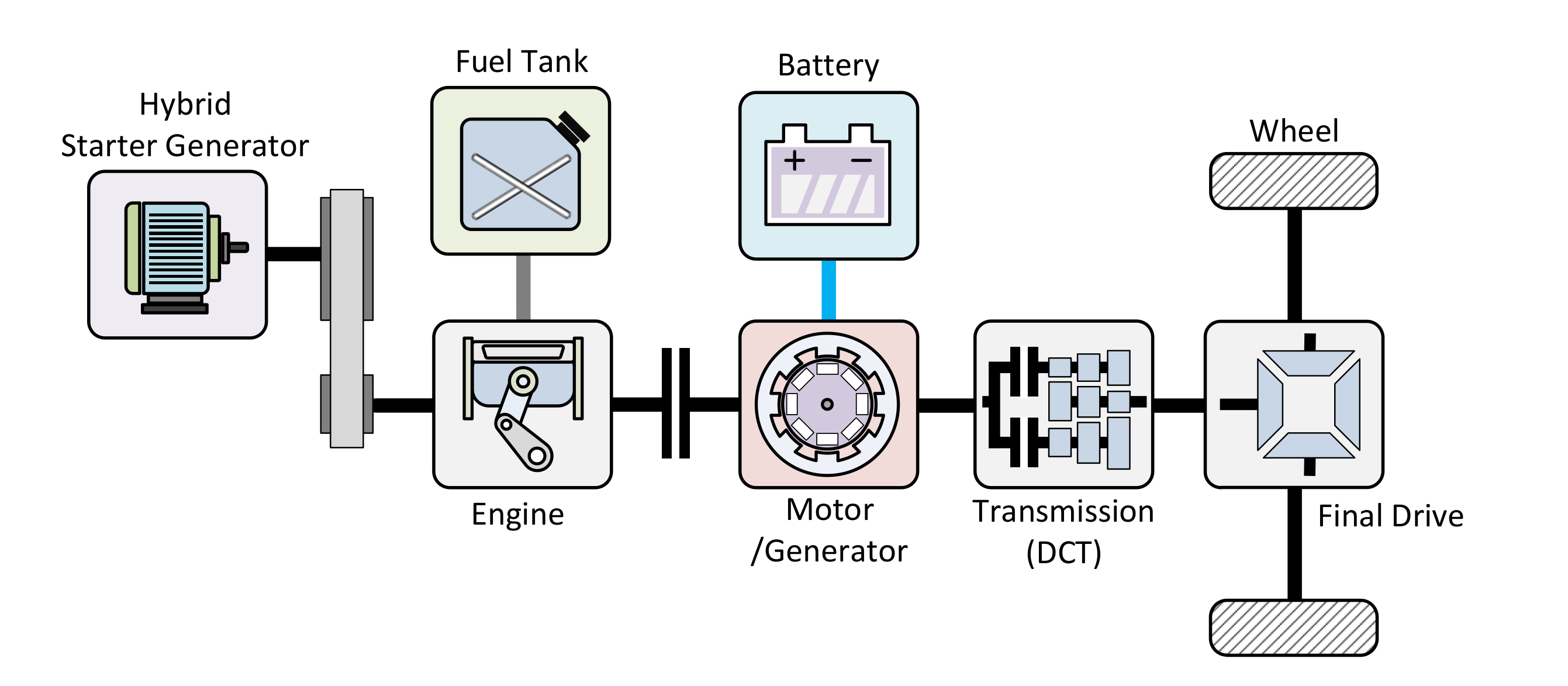
As mentioned in the previous section, HMC has been developing a parallel hybrid system similar to the Sonata and Ioniq HEV. This parallel hybrid system, as shown in Figure 1, can implement various structures of the powertrain system, such as P0 to P4, depending on the position of the motor. In the P0 system, the motor is connected with the internal combustion engine, with a belt as a starter. In the P1 system, the motor is located between the engine and the clutch. The motor can be operated in synchronization with the engine speed, while assisting power. In the P2 system, the position of the motor is between the clutch and the transmission, known as a Transmission Mounted Electric Device (TMED). This system can implement the EV mode independently of the engine. In the P3 system, the motor is assigned to the transmission output shaft; this can improve driving performance. In the P4 system, the motor is connected to the rear axle of the vehicle and it can enable All Wheel Drive (AWD). In many ways, the P0 system is a micro hybrid, the P1 system is a mild hybrid, and the P2 to P4 systems are full hybrids. The powertrain system of the Ioniq HEV is the P2 structure with dual clutches, and its configuration is shown in Figure 2. The Ioniq HEV has a main motor for traction and a hybrid generator for starting the engine. In the EV mode, the traction motor generates the demand power for driving, and if specific conditions are met, the hybrid generator starts the engine. Then, hybrid mode, in which the motor and engine produce the demand power would be operated. The specifications of the Ioniq HEV tested in this paper are shown in Table 1. This vehicle has two final drive ratios, which use the 4.188 ratio with the first to fourth gear and the 3.045 ratio with the fifth and sixth gear.

2.2. Vehicle Test

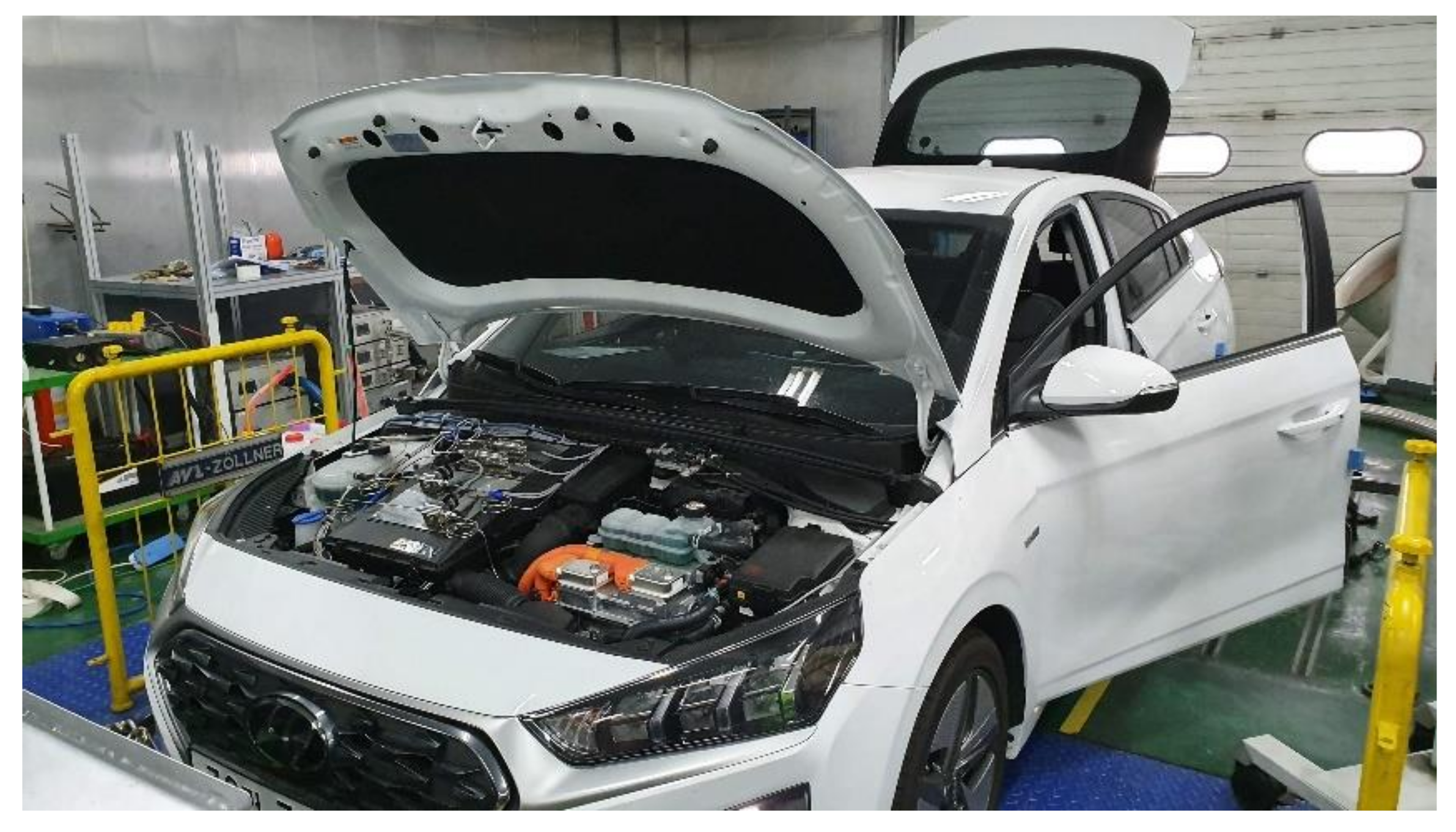
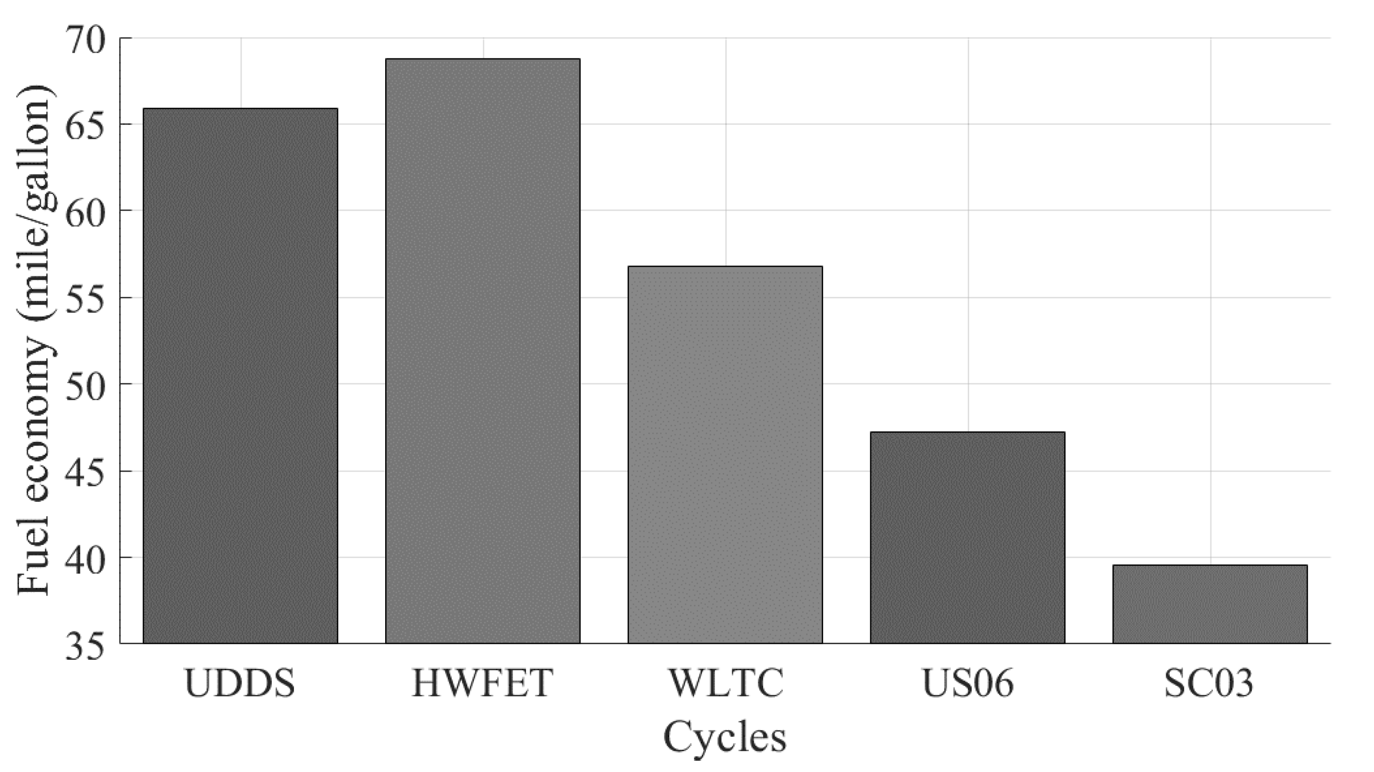
To collect the Ioniq HEV data, tests were conducted by the Korea Automotive Technology Institute and Korea Energy Agency, as shown in Figure 3. First, sensors were mounted on the vehicle to measure signals from the engine, motor, battery, etc. Then, dynamometer tests were executed including the partial load, full load, five cycles, low temperature, and extra tests. The purpose of the partial load tests is to observe the behavior of the engine in the steady state. In the partial load test, the dynamometer is set in constant speed mode and the engine speed to be measured is applied to the dynamometer. For this test, the vehicle should be in a manual mode. The load is gradually increased by adjusting the opening degree of the accel pedal, and the characteristics of the engine are measured. The purpose of the full load test is to measure the acceleration performance of the vehicle. In this test, the accel pedal is fully opened to gauge the maximum torque of the engine and motor. The five-cycle testing (including the FTP, HWFET, US06, SC03, and Cold FTP) was carried out with the environmental thermal chamber tests, and the EPA document was referenced for this test [21]. Additionally, other cycles such as the WLTC, NEDC and NIER were executed, and low temperature tests were performed for several cycles. After the dynamometer tests, the real driving tests were conducted. The real driving test data were collected on a remote storage system with data logging devices. Sixty test records were obtained from the research institutions; these data are summarized in Table 2. The fuel economy results, over several cycles, are shown in Figure 4. There are some differences between the fuel economy we measured for the UDDS and HWFET cycles and those certified by the EPA [20]. It is presumed that the reason for this is that the wheel specifications are different from those of the EPA vehicle. The Ioniq HEV has used two wheel types (196/65R15 and 225/45R17), and the wheel with 225/45R17 was used in this paper.

2.3. Precalculation for Control Analysis

Before analyzing the control strategies of the vehicle, there are several processes that need to be performed. The first is the signal alignment between the Controller Area Network (CAN) and the dynamometer signals. Since these signals have been collected through different data logging devices, the time of each signal is misaligned. For accurate control strategy analysis, signal alignment is required. For example, the wheel demand torque from the dynamometer and the engine torque from the CAN should be considered simultaneously in order to analyze the engine on/off strategies. If there is no signal alignment, it is difficult to understand the strategy. Therefore, signal alignment has been performed, by finding a shifting time that maximizes the correlation coefficient based on the vehicle speed signals from the dynamometer and the CAN. The result of signal alignment is shown in Figure 5. The equation used for signal alignment is as follows:
t s h i f t = argmax t x 1 τ · x 2 t + τ   d τ
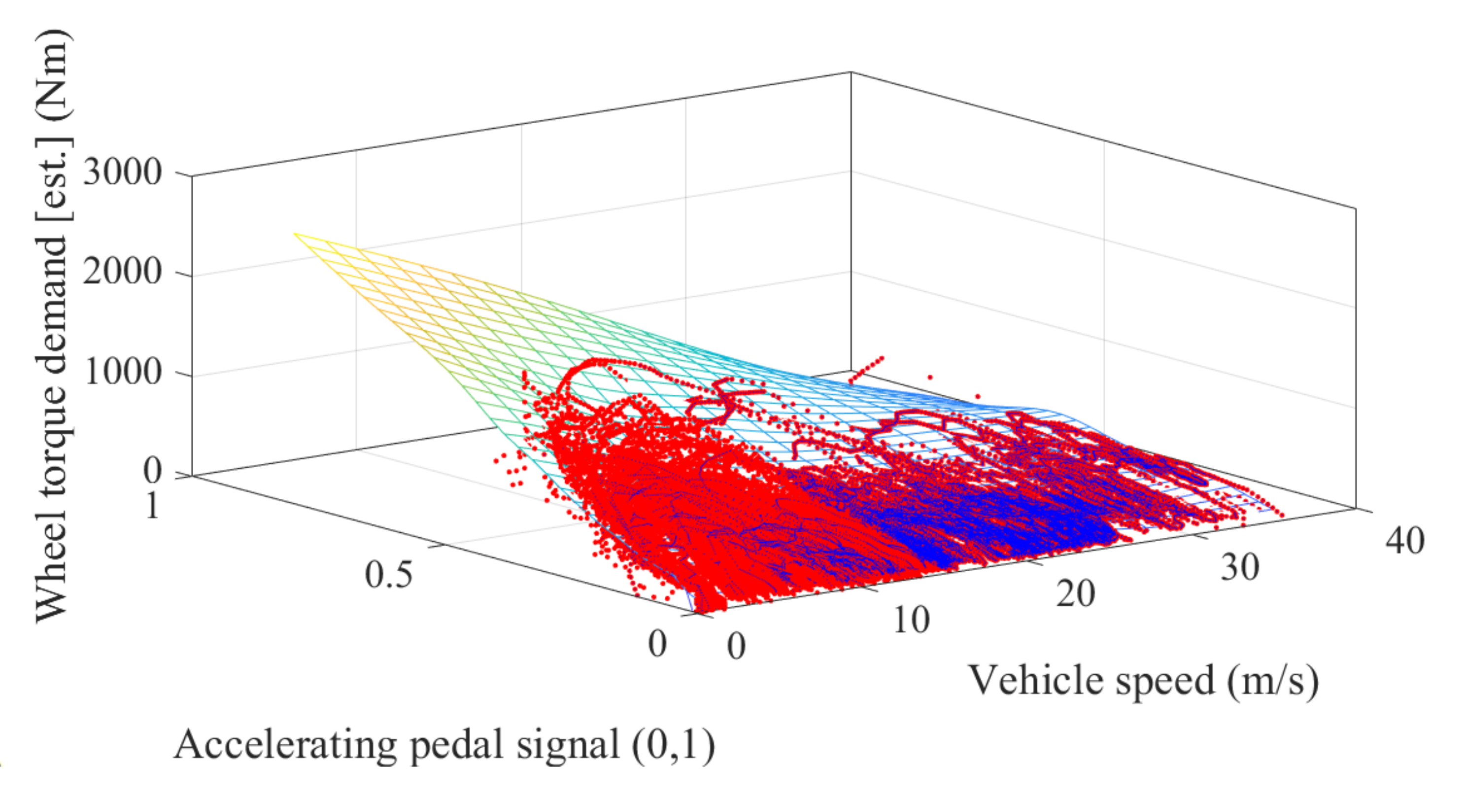
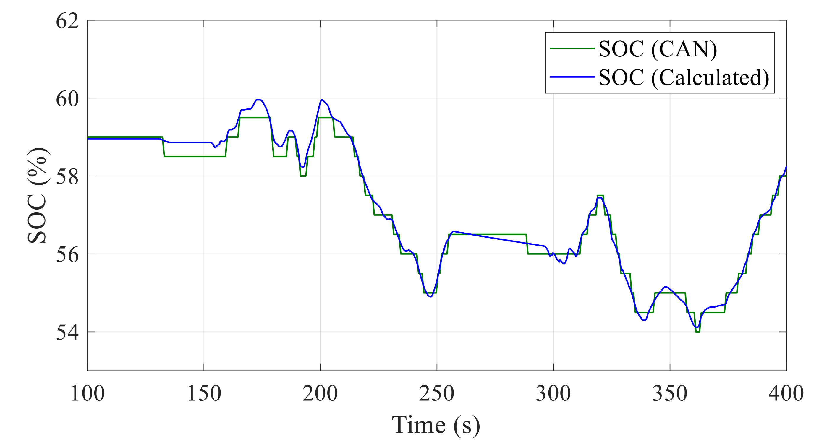
The second process is to make a wheel torque demand map. The wheel torque demand is important in analyzing control strategies for HEVs. In real driving tests, signals can be obtained via the CAN and sensors. Since the wheel torque demand signal cannot normally received from the CAN, the signal cannot be obtained without wheel torque sensors. However, it is difficult to use the sensors because they are expensive. Therefore, the wheel torque demand map has been generated, with accel pedal and vehicle speed based on the dynamometer test data, to estimate the wheel torque demand of the real driving test. The demand map is shown in Figure 6. The last item to calculate is the SOC. The SOC signal from the CAN does not accurately represent the real SOC. Therefore, the SOC has been calculated from the battery current. The equations are as follows:
S O C t = S O C 0 1 C b a t 0 t I b a t τ d τ
S O C 0 = argmin S O C 0 0 t f S O C t S O C C A N t 2 d t
where S O C 0 is the initial value of the   S O C , and C b a t is the capacity of the battery. The initial value of the SOC is determined to minimize the discrepancy between the calculated C A N signal and the calculated SOC, as shown in Figure 7.

3. Control Strategy

Unlike ICEVs and BEVs, HEVs have two power sources: an engine and a motor. Therefore, their performance depends on how the power sources are controlled. There are several control strategies, based on deterministic optimal control [22,23,24,25], intelligent optimal control [26,27,28,29], and rule-based control [30,31]. Furthermore, recently, the concept of adaptive optimal control has been proposed [32,33,34]. In all of these control strategies, it is important to determine when to turn on the engine while driving, and how to set the operating points of the engine and the electric machine. This section will discuss the control strategies of the Ioniq HEV.

3.1. Engine On/Off Control

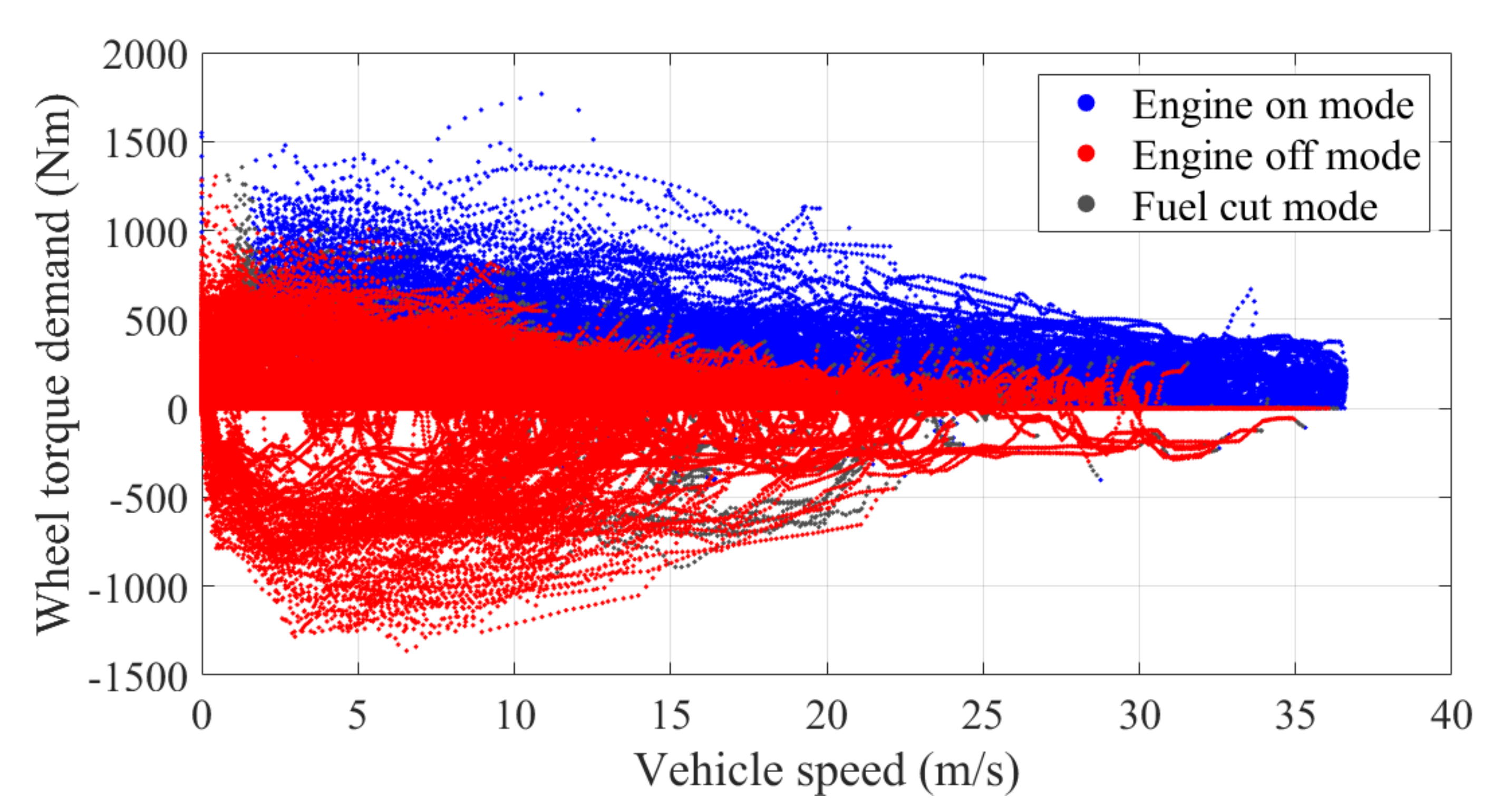
The Ioniq HEV starts driving in the EV mode and, if specific conditions are satisfied, the engine is turned on by the Hybrid Starting Generator (HSG). All operating points of the vehicle according to the engine status with all test data except the partial and full load tests are shown in Figure 8.
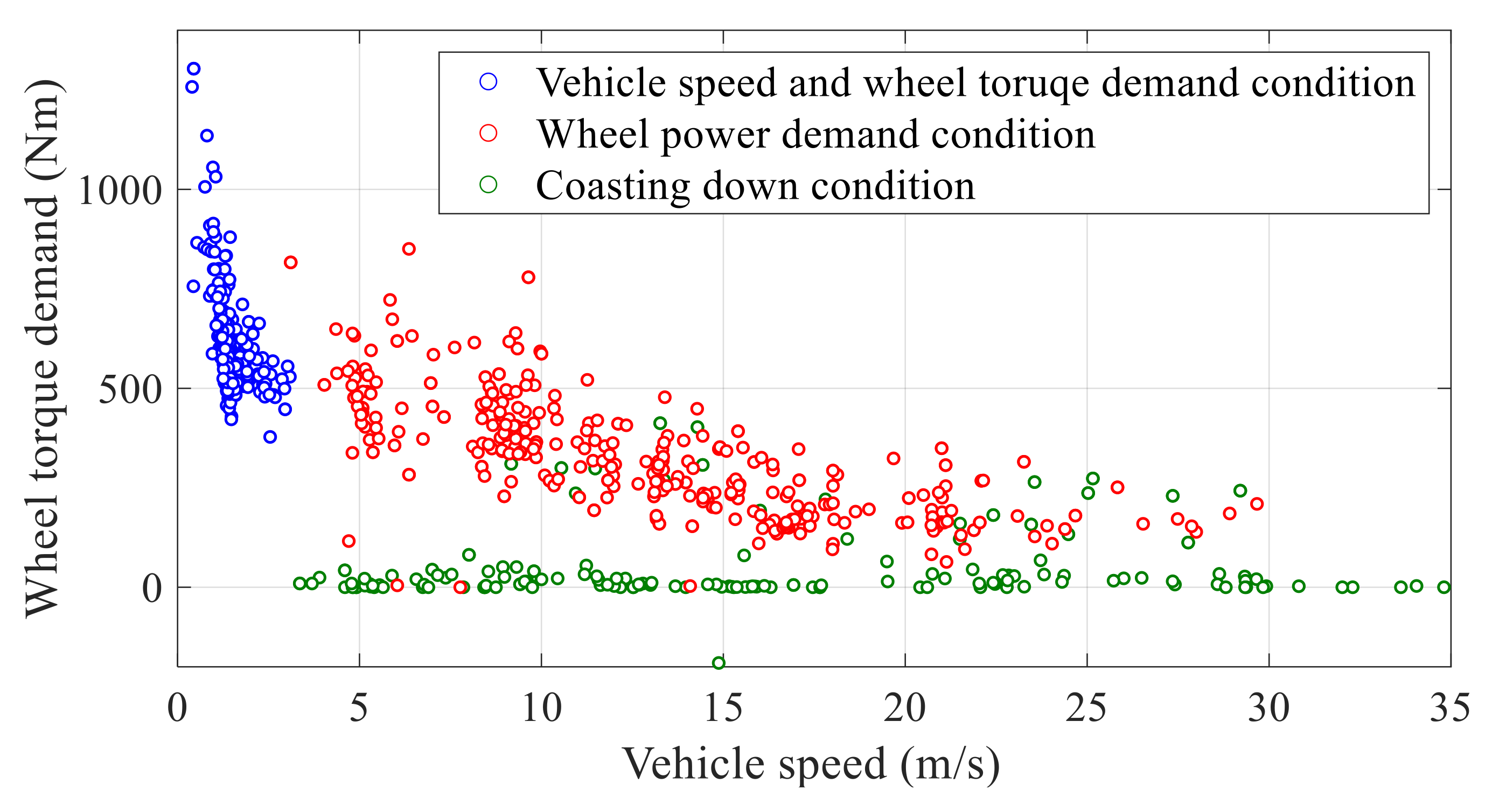
The red and blue points indicate whether the state of the engine is “on” or “off.” The gray points denote that the engine is in “fuel cut” mode. In the “fuel cut” state, the engine does not provide power but rotates at a specific speed via the motor. Based on all operating points, the points at the moment the engine is turned on are plotted in Figure 9. To understand the general “engine on” condition, some filters have been used. First, only points with the engine coolant temperature above 70 °C were considered, for excluding the effects of the engine temperature because the engine tends to turn on at the low temperature. Second, to rule out the effects of the SOC, the points with SOC values between 0.54 and 0.65 were considered. The three rules for “engine on” have been analyzed in Figure 9.
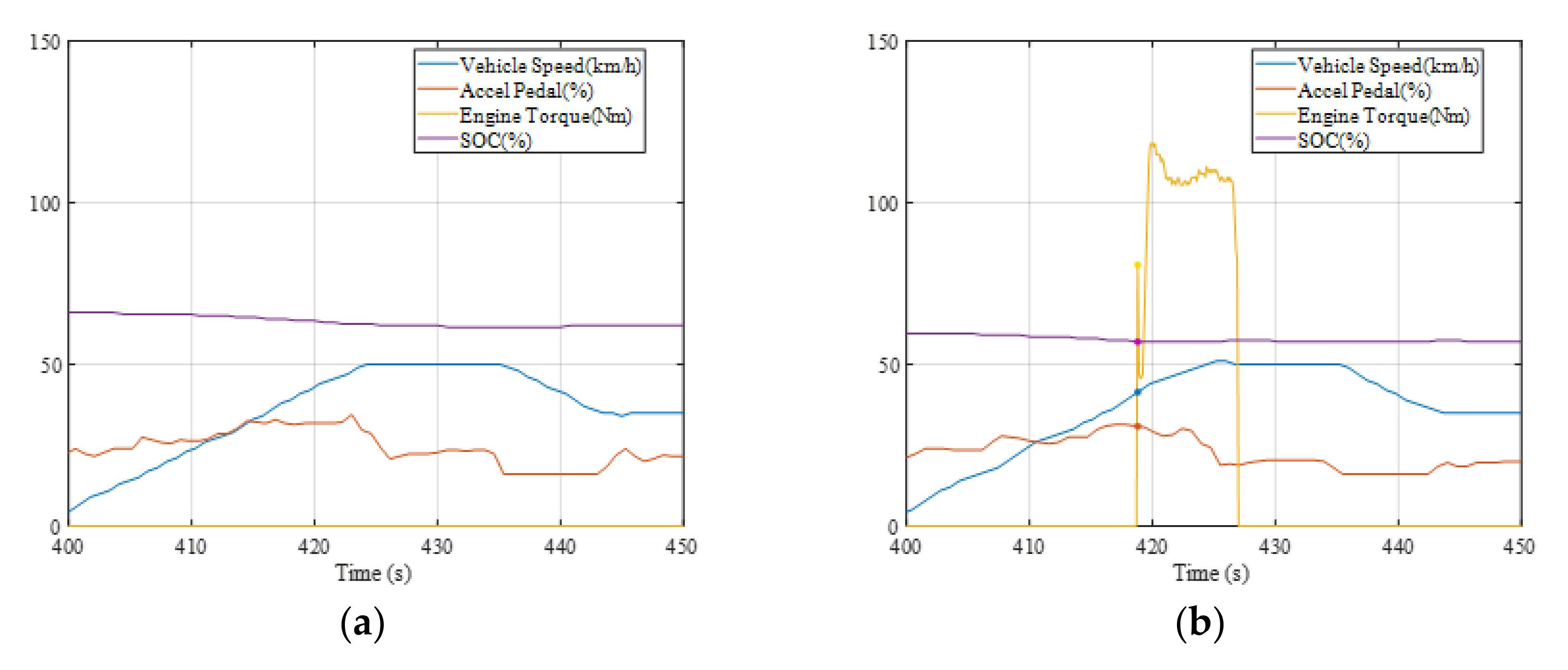
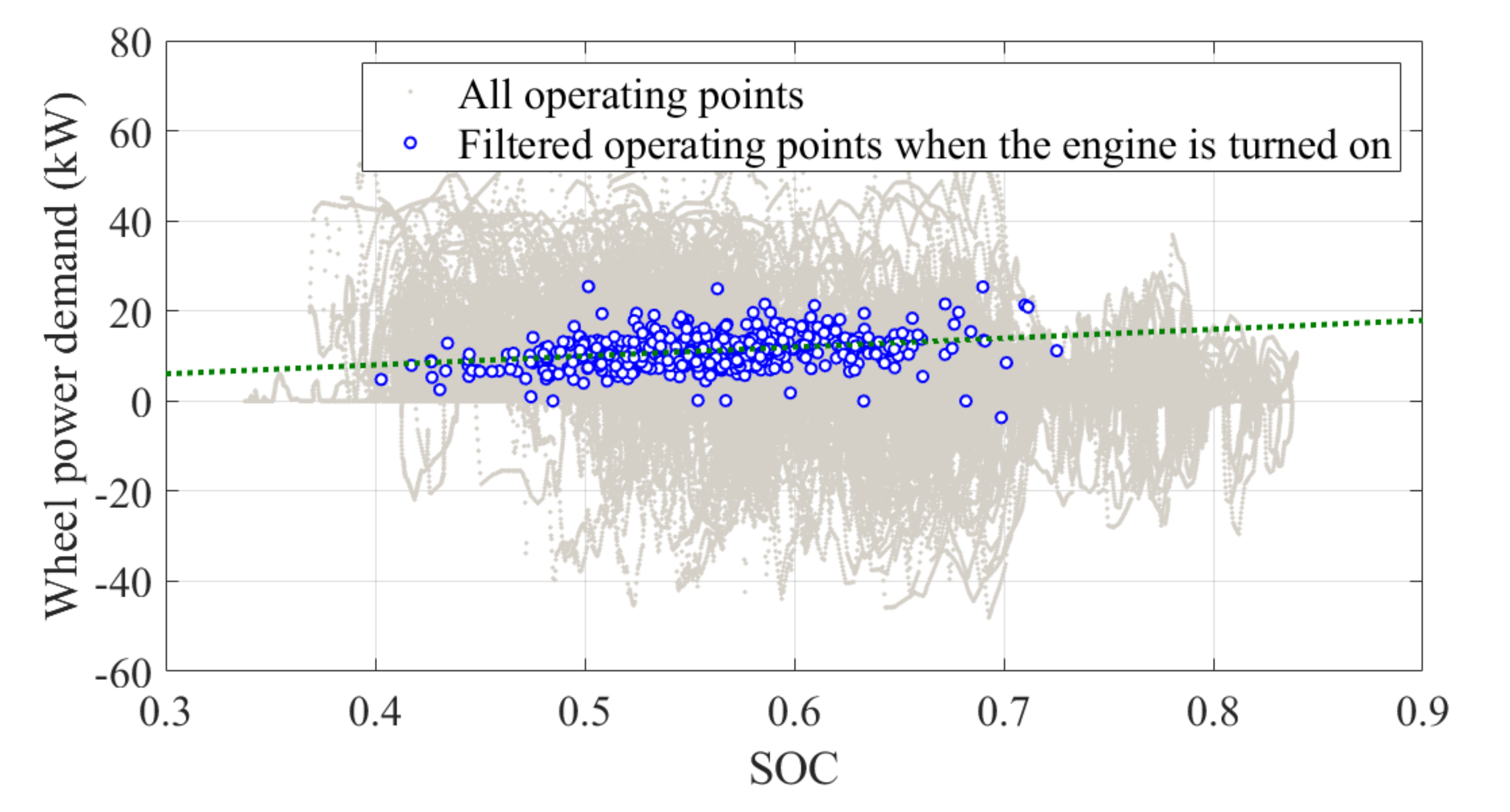
The first condition is related to the vehicle speed and wheel torque demand. It is shown that, at low speeds, the engine is turned on when the vehicle speed and wheel torque demand are above certain values. The second condition concerns the wheel power demand. It is illustrated that the engine is turned on when the wheel power demand is above a certain threshold. The last condition is associated with coasting down. If the driver steps on the accel pedal while the Ioniq HEV is coasting down, the engine would be turned on, although the value of the wheel torque is low. Commonly, HEVs have some control strategies concerning the engine on/off condition for SOC balancing. If the SOC cannot be balanced, HEVs are similar to conventional vehicles with battery and motor weight added. The engine on/off conditions related to the SOC were analyzed. Figure 10 shows the results of the dynamometer tests with the NEDC cycle. The tests have been conducted with the same external conditions, and all conditions such as the engine coolant and ambient temperature are the same. For the two tests, only the SOC results are different. The engine was not turned on at the high SOC, and the engine was turned on at the low SOC. Based on the results, it can be assumed that the engine on/off condition is related to the SOC. Figure 11 shows all operating points of the test data (in grey), as well as the operating points when the engine is turned on (in blue). To see only the impact of the SOC, several filters have been applied, such as engine temperature over 70 °C, vehicle speed over about 10km/h and engine on points exclusion due to coasting down condition. Figure 11 shows that as the SOC increases, the wheel power demand for turning on the engine increases.
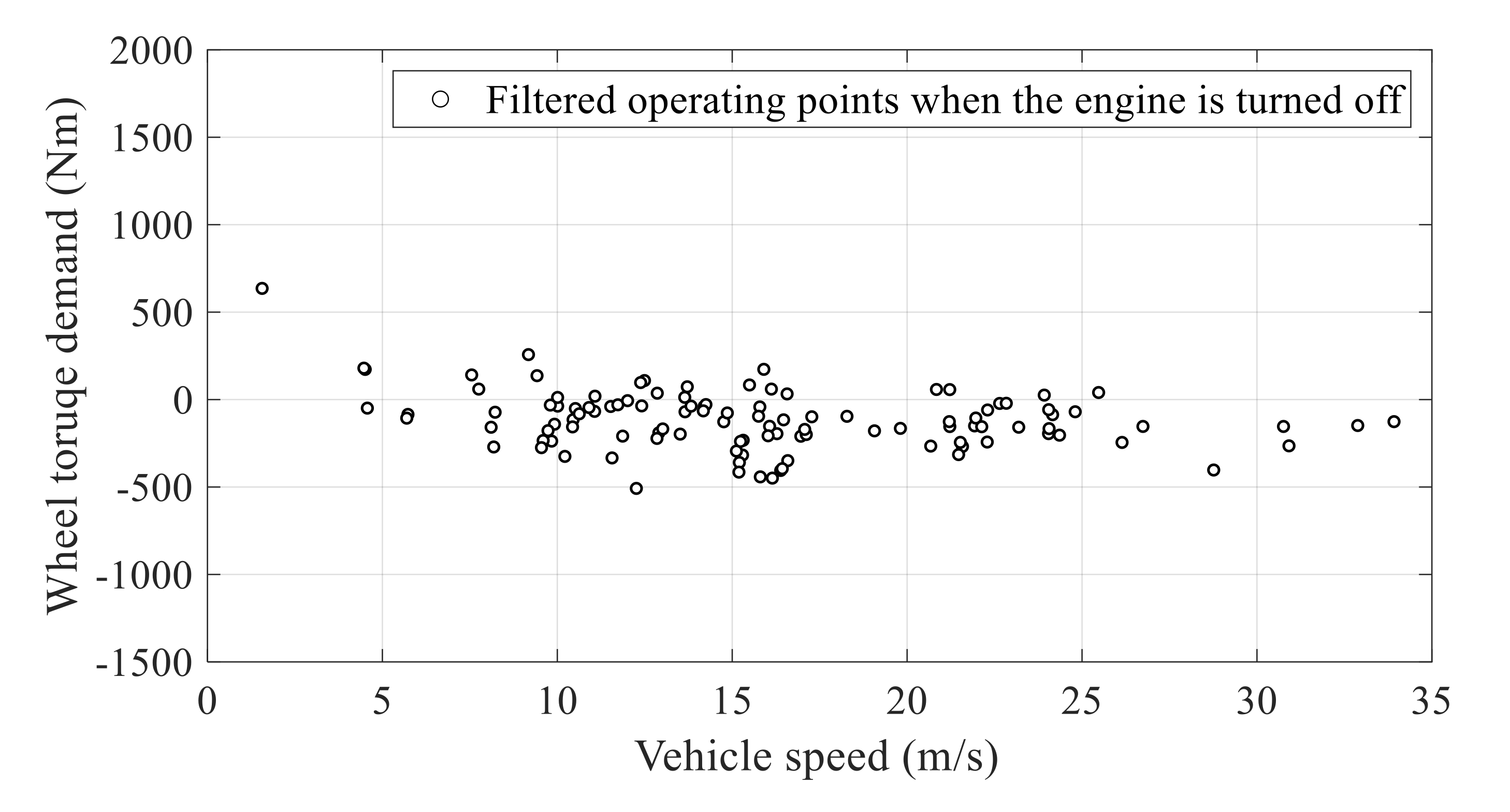
Unfortunately, it is difficult to analyze the “engine off” conditions clearly because the wheel power demand drops sharply when a driver steps off the pedal. Based on the dynamometer tests, the operating points at which the engine is turned off are shown in Figure 12. These operating points are near the zero or negative value of the wheel torque demand. For this reason, it can be assumed that conditions related to the amount of deceleration time are included, in order to recognize the occasions when a driver decelerates briefly due to the occurrence of a specific event such as a speed bump. In these cases of brief deceleration, the vehicle is often accelerated immediately afterward. However, if the engine is turned off at that time, it is unlikely to provide the desired amount of acceleration. Therefore, it is assumed that while the vehicle is decelerating, the engine is not turned off for a certain time, even though the wheel torque demand is zero.

3.2. Shifting Control Strategy

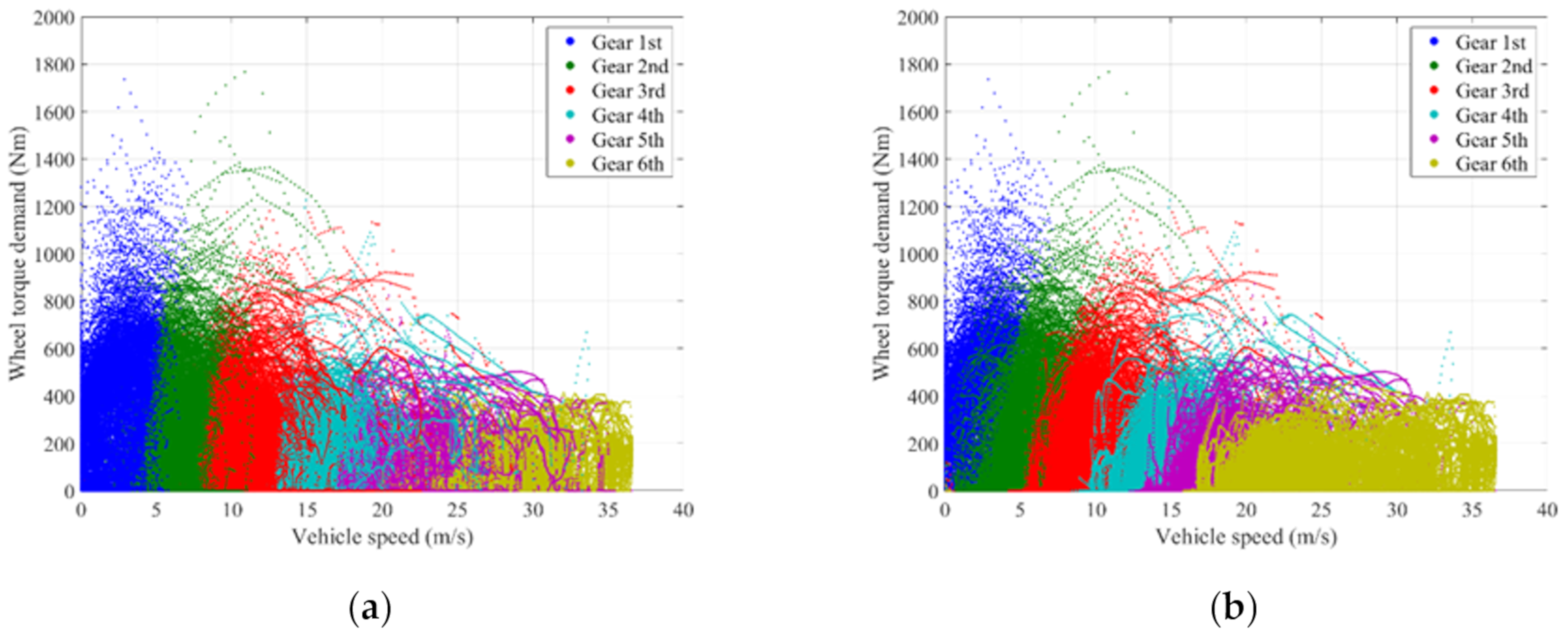
Due to the structure of the parallel hybrid system, the speeds of the motor and engine of the Ioniq HEV depend on the vehicle speed, and the operating point of the engine can be optimized by its shifting map. In particular, the Ioniq HEV has two final drive ratios, and the choice of final ratio used is determined by the gearbox. Thus, the shifting map is important in improving the efficiency and performance of the vehicle. Based on all test data except the partial and full load tests, the shifting map of the Ioniq HEV has been estimated, as shown in Figure 13. In our test results, the target gear signal cannot be found. The shifting map has been approximated based on the ratio of the motor and wheel speed, and the Ioniq HEV specifications shown in Table 1. Figure 13 shows the up and down shifting maps with hysteresis (the hysteresis can help prevent busy shifting.) These shifting maps could be utilized to develop a simulation model.

3.3. Engine and Motor Control Strategy

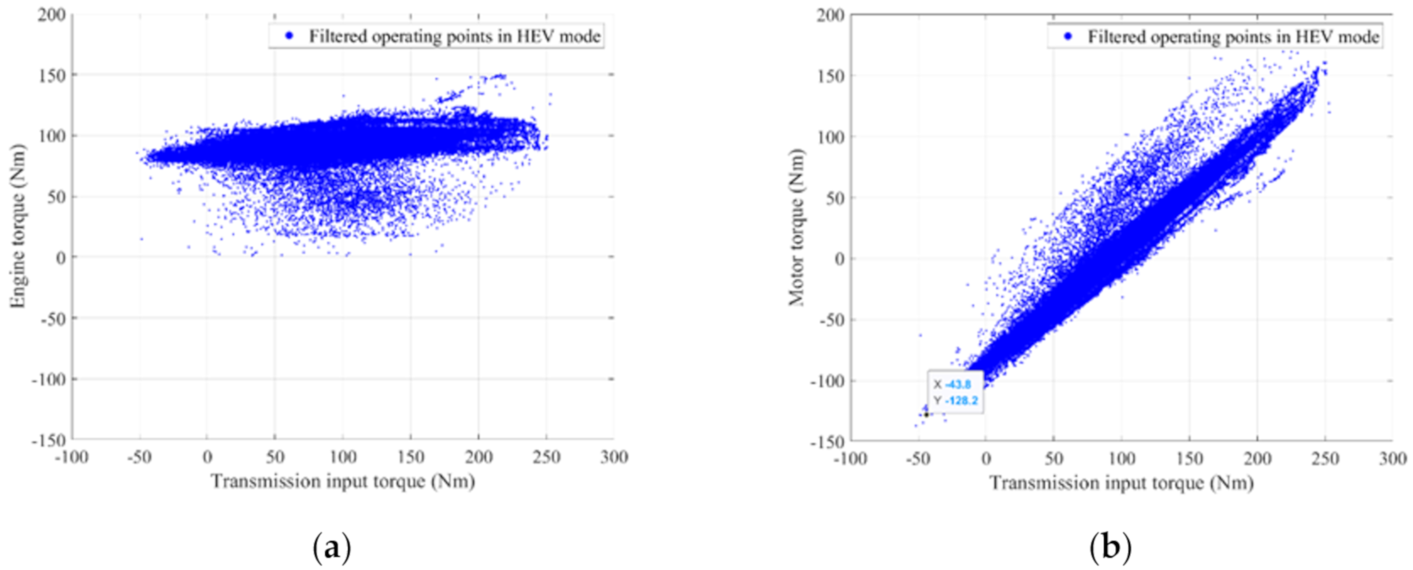
In the preceding sections, the engine on/off control and the shifting map of the Ioniq HEV have been explored. This section demonstrates how power is distributed to the engine and motor in hybrid mode. In the EV mode, all the power is produced by the motor. However, in hybrid mode, there are several combinations of engine and motor power that can fulfill the demand power for driving, and the performance depends upon which pair is selected. The Toyota Prius sets the motor power for SOC balancing, and the engine generates the remaining power on the OOL for driving [19]. The engine and motor torque of the Ioniq HEV, according to the transmission input torque, are shown in Figure 14 (based on all test data except the cold, partial, and full load tests), to analyze the power source control strategy.
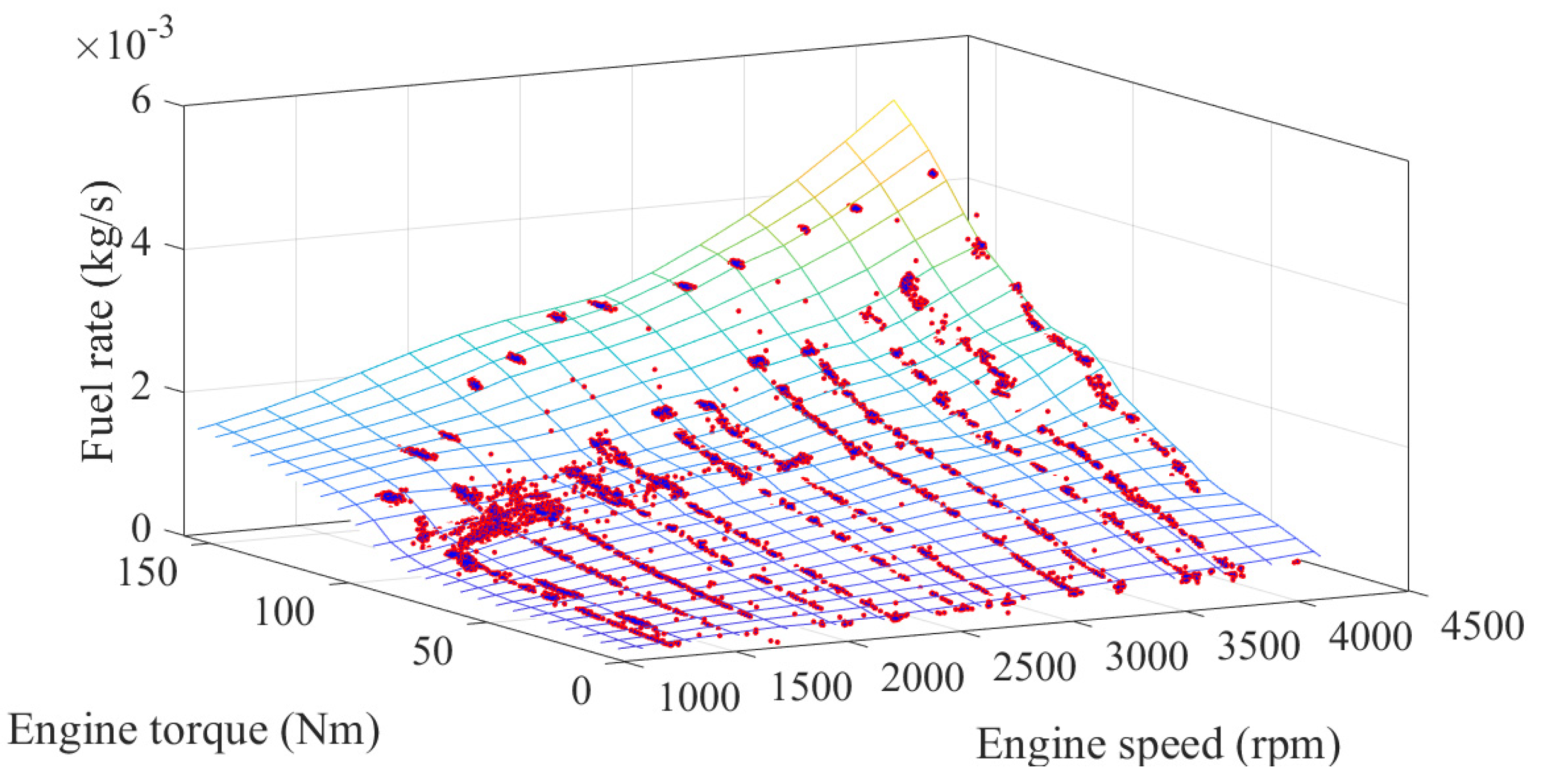
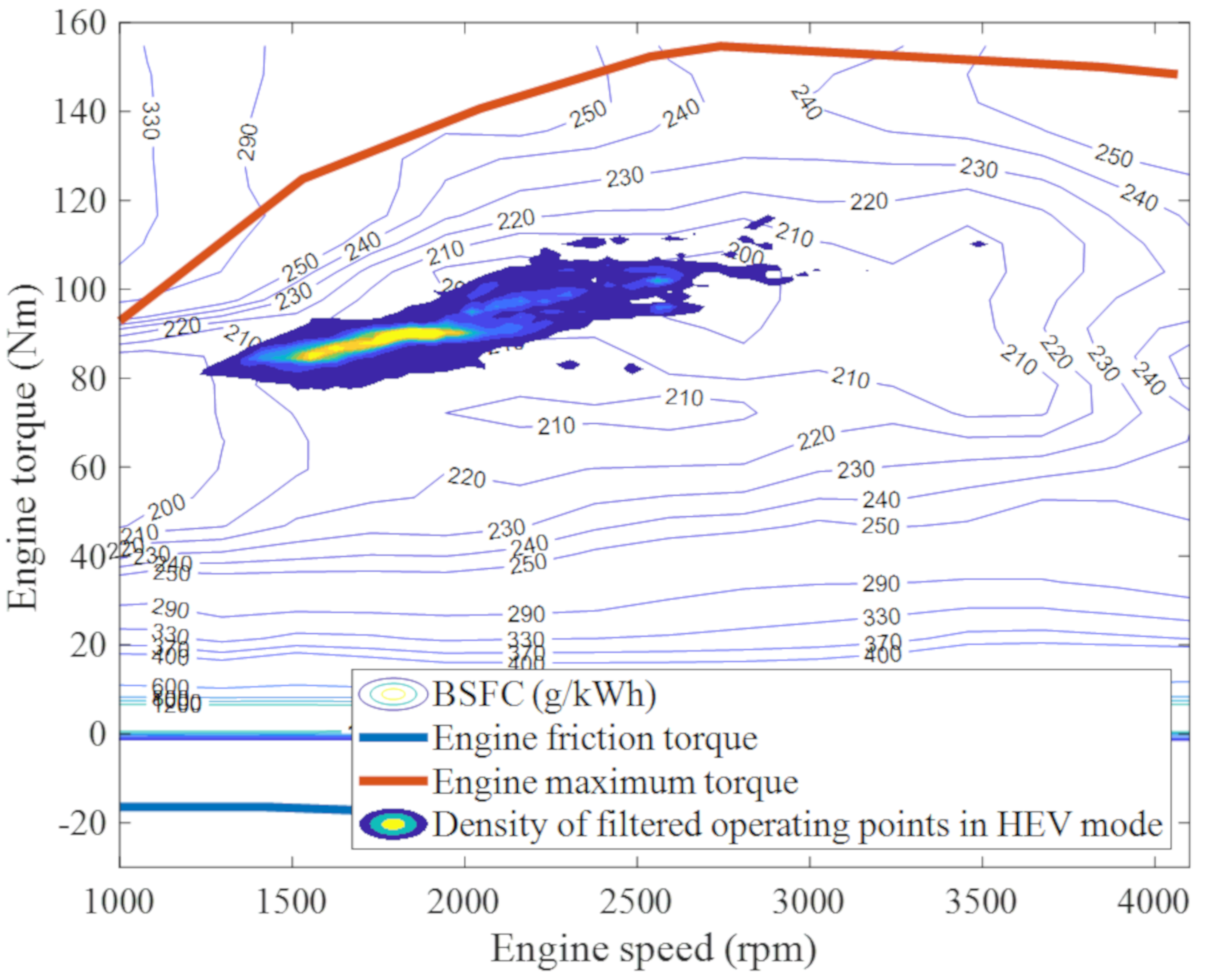
With increasing transmission input torque, the engine tends to continue to stay a specific torque, while the motor torque changes to meet the demand torque of the vehicle. That is, it can be demonstrated that the operating point of the engine is determined first, and the motor produces enough power to attain surplus or has insufficient power for driving. This is somewhat different from the way the Toyota Prius operates. It can be easily inferred that the engine will work at highly efficient points, but it is worth verifying this. The engine fuel map shown in Figure 15 was produced based on the partial load, steady state tests. The brake specific fuel consumption (BSFC) was estimated from the fuel map, and the maximum torque line of the engine was calculated from the full load test results. Section 2 demonstrates how the partial and full load tests were conducted.
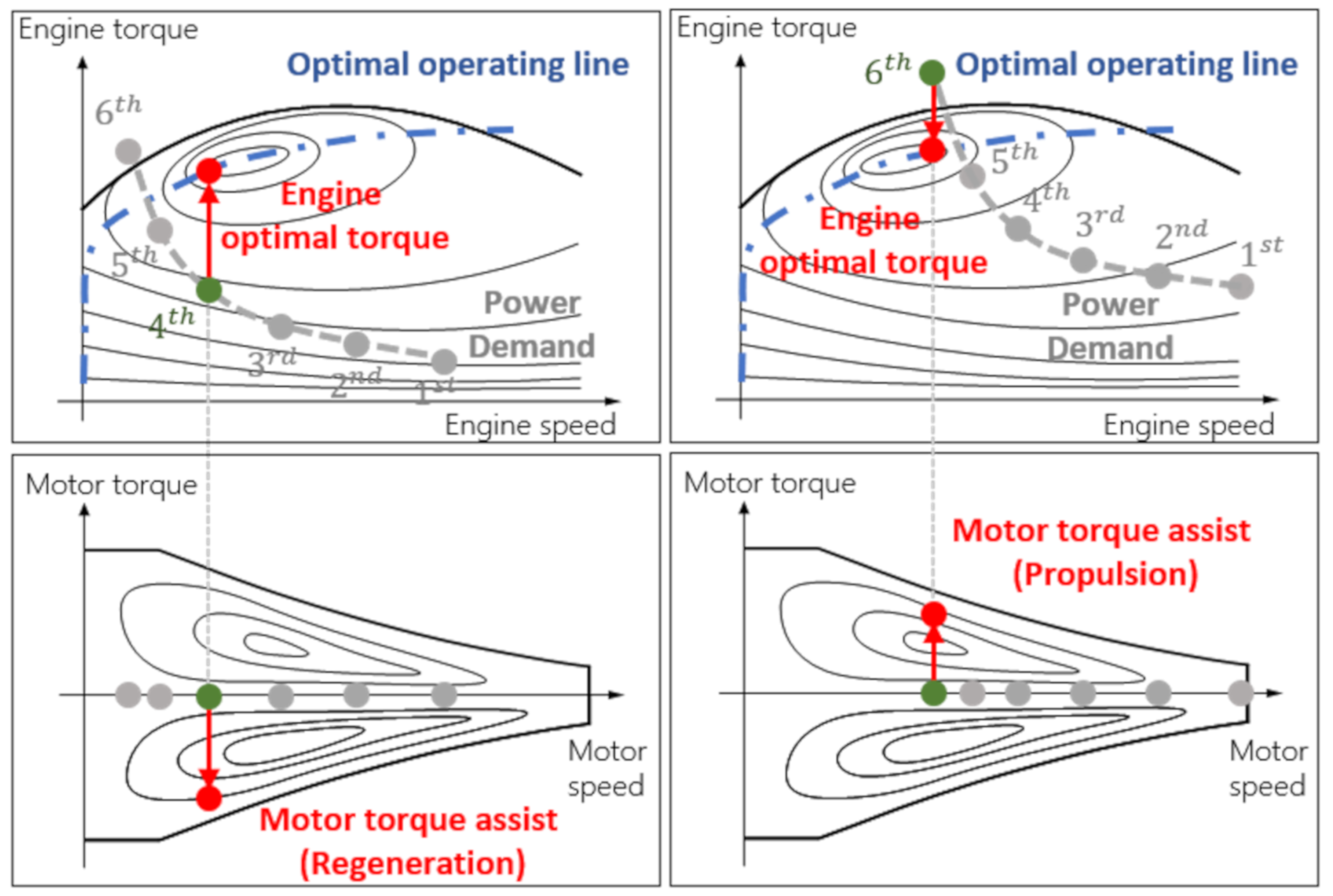
Figure 16 and Figure 17 show the operating points of the engine with the BSFC map and motor in Figure 14. With so much test data, it is not easy to tell where the power sources are mainly working by drawing the operating points as they are. To determine the engine operating area, the function that can derive the density of its operating points has been applied. It has been verified that the engine of the Ioniq HEV works in a highly efficient area with the BSFC. It can be seen that the working area of the motor is wider than that of the engine because the operating point of the engine is determined as a high efficiency area and motor torque changes according to the demand torque for driving. In most driving scenarios, if the engine is operated near the OOL, the power generated by the engine would be greater than that required for driving, and surplus power would be regenerated by the motor. That is why the main working area of the motor is the negative torque range, as shown in Figure 17. The power source control strategy analyzed in this paper is conceptually illustrated in Figure 18.
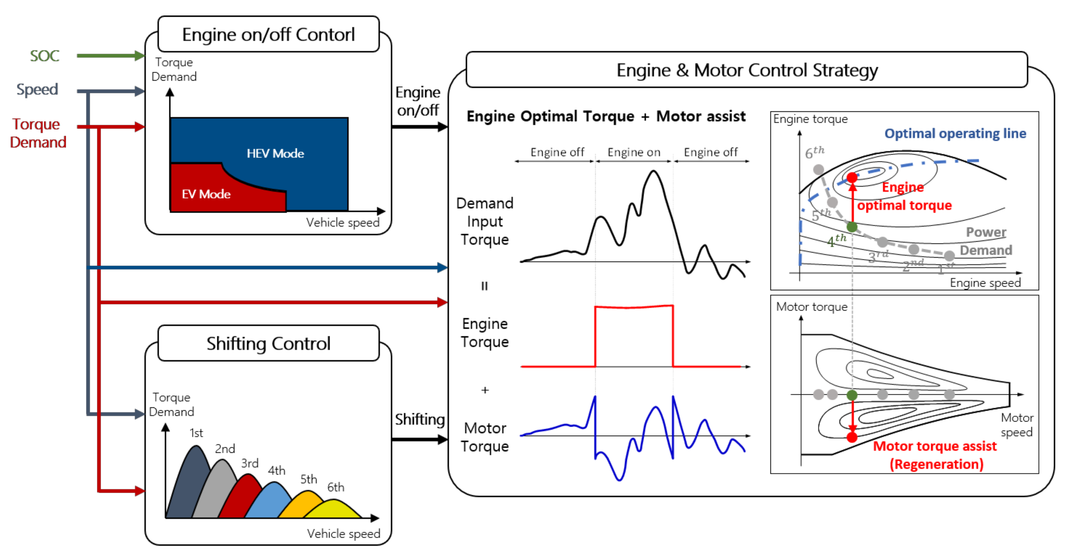
The engine speed is determined with a specific gear ratio and the engine torque would be controlled so that it is operated on the OOL. At this time, if the engine optimal torque is greater than the torque demand for driving, the motor would be regenerated; otherwise, the motor would generate the positive torque for propulsion. An overview of the control strategies analyzed in this paper is shown in Figure 19. First, the target gear is determined, and whether the engine is turned on or off. Then, if the engine is turned off, the vehicle would be driving in the EV mode. If the engine is turned on, it would be operated near the OOL and the motor would assist the engine.

4. Conclusions

This study provides analyzed results for the control strategy of Hyundai’s Ioniq Hybrid, based on test data obtained from a chassis dynamometer and real driving. The parallel hybrid system implements an electric motor, which enables the pure electric driving mode under low power demand. As the engine clutch is engaged, the engine turns on if the demand power increases, and the system goes into the hybrid driving mode. The motor is assisting the engine in hybrid mode, so that the engine can operate in a high efficiency region, in which the speed of the engine is determined by the predefined shifting map. The operating target of the engine is selected to maximize the engine efficiency; this has been shown by comparing the operating points with the obtained engine fuel consumption map. The overall control concept is summarized in the flow chart, from which all control targets of powertrain components can be determined. This paper could be useful to engineers who want to develop simulation models or to understand the control concept of HEVs, in that it not only provides operating behaviors, but also analyzes the supervisory concept of heuristic control applied in the real-world HEV.

Author Contributions

Conceptualization, W.L. and N.K.; Data curation, B.L., J.C. and D.K.; Formal analysis, W.L., T.K. and J.J.; Methodology, W.L., T.K. and J.J.; Funding acquisition, N.K., J.C., D.K., and B.L.; Investigation, B.L., J.C. and D.K.; Project administration, N.K.; Software, W.L. and T.K.; Visualization, W.L.; Writing-original draft, W.L.; Writing-review and editing, N.K. All authors have read and agreed to the published version of the manuscript.

Funding

This work was supported by the Technology Innovation Program (20011834, Development of application technologies for heavy duty fuel cell electric trucks using multi-input motor based 400kW class multi speed electrified powertrain system) funded by the Ministry of Trade, Industry and Energy (MOTIE, Korea). This work was also supported by “Human Resources Program in Energy Technology” of the Korea Institute of Energy Technology Evaluation and Planning (KETEP), granted financial resource from the Ministry of Trade, Industry &Energy, Republic of Korea (No. 20194010201740).

Conflicts of Interest

The authors declare no conflict of interest.

References

  1. Taniguchi, M.; Yashiro, T.; Takizawa, K.; Baba, S.; Tsuchida, M.; Mizutani, T.; Endo, H.; Kimura, H. Development of New Hybrid Transaxle for Compact-Class Vehicles. SAE Techn. Pap. 2016. [Google Scholar] [CrossRef]
  2. Furukawa, T.; Ibaraki, R.; Kimura, H.; Kondo, K.; Watanabe, M.; Mizutani, T.; Hattori, H.; Takasaki, A. Development of New Hybrid Transaxle for Sub-Compact-Class Vehicles. SAE Techn. Pap. 2012. [Google Scholar] [CrossRef]
  3. Fushiki, S. The new generation front wheel drive hybrid system. SAE Int. J. Altern. Powertrains 2016, 5, 109–114. [Google Scholar] [CrossRef]
  4. Imamura, T.; Tabata, A.; Matsubara, T.; Iwase, Y.; Kumazaki, K.; Imai, K. Concept and Approach of Multi Stage Hybrid Transmission. SAE Techn. Pap. 2017. [Google Scholar] [CrossRef]
  5. Kato, S.; Ando, I.; Ohshima, K.; Matsubara, T.; Hiasa, Y.; Furuta, H.; Mori, Y. Development of multi stage hybrid system for new Lexus Coupe. SAE Int. J. Altern. Powertrains 2017, 6, 136–144. [Google Scholar] [CrossRef]
  6. Okuda, K.; Yasuda, Y.; Adachi, M.; Tabata, A.; Suzuki, H.; Takagi, K.; Atarashi, T.; Horie, R. Development of multi stage hybrid transmission. SAE Int. J. Altern. Powertrains 2017, 6, 77–83. [Google Scholar] [CrossRef]
  7. Miller, M.A.; Holmes, A.G.; Conlon, B.M.; Savagian, P.J. The GM “Voltec” 4ET50 Multi-mode electric transaxle. SAE Int. J. Engines 2011, 4, 1102–1114. [Google Scholar] [CrossRef]
  8. Zhang, X.; Li, S.E.; Peng, H.; Sun, J. Design of multimode power-split hybrid vehicles—A case study on the voltec powertrain system. IEEE Trans. Veh. Technol. 2016, 65, 4790–4801. [Google Scholar] [CrossRef]
  9. Conlon, B.M.; Blohm, T.; Harpster, M.; Holmes, A.; Palardy, M.; Tarnowsky, S.; Zhou, L. The next generation “Voltec” extended range EV propulsion system. SAE Int. J. Altern. Powertrains 2015, 4, 248–259. [Google Scholar] [CrossRef]
  10. Holmes, A.; Liu, J.; Ames, D.; Neelakantan, V.; Rahman, K.; Grewe, T. General Motors Electric Variable Transmission for Cadillac CT6 Sedan. SAE Tech. Pap. 2016. [Google Scholar] [CrossRef]
  11. Lee, W.; Park, J.; Kim, N. Analysis of transmission efficiency of a plug-in hybrid vehicle based on operating modes. Int. J. Precis. Eng. Manuf. Green Technol. 2019. [Google Scholar] [CrossRef]
  12. Wi, J.; Kim, H.; Yoo, J.; Son, H.; Kim, H.; Kim, B. Energy consumption of parallel type hybrid electric vehicle with continuously variable transmission using electric oil pump. In Proceedings of the 2018 Thirteenth International Conference on Ecological Vehicles and Renewable Energies (EVER), Monte Carlo, Monaco, 10–12 April 2018. [Google Scholar] [CrossRef]
  13. Jeoung, H.; Lee, K.; Kim, N. Methodology for finding maximum performance and improvement possibility of rule-based control for parallel type-2 hybrid electric vehicles. Energies 2019, 12, 1924. [Google Scholar] [CrossRef] [Green Version]
  14. Aoyama, M.; Deng, J. Visualization and quantitative evaluation of eddy current loss in bar-wound type permanent magnet synchronous motor for mild-hybrid vehicles. CES Trans. Electr. Mach. Syst. 2019, 3, 269–278. [Google Scholar] [CrossRef]
  15. Biswas, P. Adapting SUV AWD powertrain to P0/P2/P4 hybrid EV architecture: Integrative packaging and capability study. IEEE Transp. Electrif. Conf. (ITEC-India) 2017. [Google Scholar] [CrossRef]
  16. Haußmann, M.; Barroso, D.; Vidal, C.; Bruck, L.; Emadi, A. A Novel Multi-Mode Adaptive Energy Consumption Minimization Strategy for P1-P2 Hybrid Electric Vehicle Architectures. IEEE Trans. Electrif. Conf. Expo (ITEC) 2019. [Google Scholar] [CrossRef]
  17. Tian, X.; He, R.; Xu, Y. Design of an energy management strategy for a parallel hybrid electric bus based on an IDP-ANFIS scheme. IEEE Access 2018, 6, 23806–23819. [Google Scholar] [CrossRef]
  18. Kim, N.; Rousseau, A. Thermal impact on the control and the efficiency of the 2010 Toyota Prius hybrid electric vehicle. Proc. Inst. Mech. Eng. Part D J. Automob. Eng. 2016, 230, 82–92. [Google Scholar] [CrossRef]
  19. Kim, N.; Rousseau, A.; Rask, E. Vehicle-level control analysis of 2010 Toyota Prius based on test data. Proc. Inst. Mech. Eng. Part D J. Automob. Eng. 2012, 226, 1483–1494. (In English) [Google Scholar] [CrossRef]
  20. US Environmental Protection Agency (EPA). Fuel Economy Data. 2020. Available online: https://www.fueleconomy.gov/feg/download.shtml (accessed on 5 August 2020).
  21. US Environmental Protection Agency (EPA). Final Rule for Fuel Economy Labeling of Motor Vehicles: Revisions To Improve Calculation of Fuel Economy Estimates. 2006. Available online: https://www.epa.gov/regulations-emissions-vehicles-and-engines/final-rule-fuel-economy-labeling-motor-vehicles-revisions (accessed on 5 August 2020).
  22. Kim, N.; Rousseau, A. Sufficient conditions of optimal control based on Pontryagin’s minimum principle for use in hybrid electric vehicles. Proc. Inst. Mech. Eng. Part D J. Automob. Eng. 2012, 226, 1160–1170. [Google Scholar] [CrossRef]
  23. Kim, N.; Cha, S.; Peng, H. Optimal control of hybrid electric vehicles based on Pontryagin’s minimum principle. IEEE Trans. Control Syst. Technol. 2011, 19, 1279–1287. [Google Scholar]
  24. Kim, N.; Cha, S.W.; Peng, H. Optimal equivalent fuel consumption for hybrid electric vehicles. IEEE Trans. Control Syst. Technol. 2012, 20, 817–825. [Google Scholar]
  25. Kim, N.W.; Lee, D.H.; Zheng, C.; Shin, C.; Seo, H.; Cha, S.W. Realization of PMP-based control for hybrid electric vehicles in a backward-looking simulation. Int. J. Automot. Technol. 2014, 15, 625–635. (In English) [Google Scholar] [CrossRef]
  26. Wu, J.; Zou, Y.; Zhang, X.; Liu, T.; Kong, Z.; He, D. An online correction predictive EMS for a hybrid electric tracked vehicle based on dynamic programming and reinforcement learning. IEEE Access 2019, 7, 98252–98266. [Google Scholar] [CrossRef]
  27. Lee, H.; Song, C.; Kim, N.; Cha, S.W. Comparative analysis of energy management strategies for HEV: Dynamic programming and reinforcement learning. IEEE Access 2020, 8, 67112–67123. [Google Scholar] [CrossRef]
  28. Lin, X.; Wang, Y.; Bogdan, P.; Chang, N.; Pedram, M. Reinforcement learning based power management for hybrid electric vehicles. IEEE/ACM Int. Conf. Comput. -Aided Des. (ICCAD) 2014. [Google Scholar] [CrossRef]
  29. Liu, C.; Murphey, Y.L. Power management for Plug-in Hybrid Electric Vehicles using Reinforcement Learning with trip information. In Proceedings of the 2014 IEEE Transportation Electrification Conference and Expo (ITEC), Dearborn, MI, USA, 15–18 June 2014; pp. 1–6. [Google Scholar]
  30. Sorrentino, M.; Rizzo, G.; Arsie, I. Analysis of a rule-based control strategy for on-board energy management of series hybrid vehicles. Control Eng. Pract. 2011, 19, 1433–1441. [Google Scholar] [CrossRef]
  31. Banvait, H.; Anwar, S.; Chen, Y. A rule-based energy management strategy for plugin hybrid electric vehicle (PHEV). Proc. Am. Control Conf. 2009. [Google Scholar] [CrossRef]
  32. Lee, W.; Jeoung, H.; Park, D.; Kim, N. An adaptive concept of PMP-based control for saving operating costs of extended-range electric vehicles. IEEE Trans. Veh. Technol. 2019, 68, 11505–11512. [Google Scholar] [CrossRef]
  33. Liu, Y.; Li, J.; Lei, Z.; Li, W.; Qin, D.; Chen, Z. An Adaptive Equivalent Consumption Minimization Strategy for Plug-In Hybrid Electric Vehicles Based on Energy Balance Principle. IEEE Access 2019, 7, 67589–67601. [Google Scholar] [CrossRef]
  34. Kim, N.; Jeong, J.; Zheng, C. Adaptive Energy Management Strategy for Plug-in Hybrid Electric Vehicles with Pontryagin’s Minimum Principle Based on Daily Driving Patterns. Int. J. Precis. Eng. Manuf. Green Technol. 2019. [Google Scholar] [CrossRef]
Figure 1. Parallel Hybrid System Configuration.
Energies 13 04092 g001
Figure 2. Powertrain System Configuration of Ioniq HEV.
Energies 13 04092 g002
Figure 3. Dynamometer Test of Ioniq HEV.
Energies 13 04092 g003
Figure 4. Fuel Economy according to Cycles with Hot Test: Urban Dynamometer Driving Schedule (UDDS), Highway Fuel Economy Test (HWFET), Worldwide Harmonized Light Vehicles Test Cycles (WLTC), High Acceleration Aggressive Driving Schedule (US06), Use of Air Conditioning Driving Schedule (SC03).
Energies 13 04092 g004
Figure 5. Signal Alignment of Vehicle Speed Signals.
Energies 13 04092 g005
Figure 6. Estimated Wheel Demand Torque Map.
Energies 13 04092 g006
Figure 7. Comparing SOC Signal from CAN with SOC Calculated.
Energies 13 04092 g007
Figure 8. All Operating Points According to the Engine Status.
Energies 13 04092 g008
Figure 9. “Engine on” Conditions with Filters Applied.
Energies 13 04092 g009
Figure 10. Dynamometer Test Results with NEDC Cycle: (a) NEDC Cycle Test Results with High SOC, (b) NEDC Cycle Test Results with Low SOC.
Energies 13 04092 g010
Figure 11. Operating Points When the Engine is Turned on According to the SOC.
Energies 13 04092 g011
Figure 12. Operating Points When the Engine is Turned off.
Energies 13 04092 g012
Figure 13. Estimated Shifting Map of Ioniq HEV: (a) Up Shifting Map, (b) Down Shifting Map.
Energies 13 04092 g013
Figure 14. Engine and Motor Torque According to the Transmission Input Torque: (a) Engine Torque in Hybrid Mode, (b) Motor Torque in Hybrid Mode.
Energies 13 04092 g014
Figure 15. Engine Fuel Map Based on Load Tests.
Energies 13 04092 g015
Figure 16. Density of Operating Points of the Engine with BSFC.
Energies 13 04092 g016
Figure 17. Density of Operating Points of the Motor.
Energies 13 04092 g017
Figure 18. Concept of Power Source Control Strategy.
Energies 13 04092 g018
Figure 19. Control Strategies of the Ioniq HEV.
Energies 13 04092 g019
Table 1. Specifications of Ioniq HEV.
ComponentsValue
Model Year2020 Year
Curb Weight1410 kg
Engine1.6 L, 78 kW@5700 rpm
Motor32 kW/170 Nm
BatteryLi-ion, 1.56 kWh
Gear Ratio3.867/2.217/1.371/0.930/0.956/0.767
Final Drive Ratio4.188@1~4Gear/3.045@5,6Gear
Wheel225/45R17
Table 2. Dynamo and Real Driving Test Data.
TypeComponentsNumber
Dynamometer TestPartial Load Test5
Full Load Test9
Cold Test13
Hot Test26
Real Driving TestCold Test5
Hot Test2