1. Introduction
Real-time digital simulation and hardware-in-the-loop (HIL) testing has been used in the power industry for over twenty-five years [
1]. Originally developed as a solution for flexibly testing the control and protection associated with high-voltage direct current (HVDC) projects, the application of the technology is now more varied. Hardware-in-the-loop testing is used by electric utilities, educational and research institutions, and consultants. Much of the recent application of real-time simulation has been related to grid modernization technologies and projects.
Real-time simulators run an electromagnetic transient (EMT) model of the power system. EMT simulation tools are well-established in the power industry. In providing a time-varying, instantaneous value output, EMT models represent the behavior of the network over a wide frequency range and allow for a greater depth of analysis than traditional phasor-based modelling approaches such as load flow or transient stability analysis. As the modern power system continues to move away from a conventional synchronous machine-based structure, EMT simulation results become increasingly relevant due to their ability to provide results over a large range of frequencies. For systems containing generation or load interfaced via power electronic converters, phasor-based modelling tools can provide optimistic results, as they lack the ability to represent low-level converter controls or capture fast network dynamics during transient conditions [
2]. EMT simulation overcomes these issues and is thus increasingly used from a power systems planning and operations perspective. Many established EMT tools, including real-time simulators, are based on the Dommel Algorithm for network solution [
3]. Real-time simulators are distinct from PC-based EMT software tools in that they make use of dedicated parallel processing hardware to execute the simulation in real time. Continuous real-time operation allows for external equipment to be connected to the simulated network in a closed loop—referred to as HIL testing. HIL testing offers the ability to test multiple devices simultaneously, the ability to represent and study the behavior of power electronics (and their interaction with protection and control), and the flexibility and safety that comes with testing in a controlled laboratory environment rather than on site. Testing real equipment rather than a model of the device allows for greater confidence in equipment behavior and reduces issues experienced during commissioning and field operation.
The term “timestep” is used to describe the time between consecutive instantaneous outputs of the EMT simulation. The timestep is related to the sampling frequency of the simulation and determines the frequency bandwidth of signals that can be accurately reproduced. Real-time simulators must complete all calculations related to solving the network in real world time equal to or less than the simulation timestep. For protection and control testing, a timestep in the 30 to 60 microsecond (µs) range is generally used. The required timestep should be determined by the user based on their required results and dynamics of interest and can be adjusted as necessary.
Real-time simulators capable of HIL testing have several components: the parallel processing hardware platform for running the simulation, input/output (I/O) facilities in order to create the closed-loop interface with the device(s) being tested, and the graphical user interface which runs on the user’s PC and allows for dynamic interaction with the simulation in real time. The graphical user interface includes the power system modelling library, another key component of the real-time simulator.
As the technology gains popularity and widespread use, it is critical that the manufacturers of real-time simulators develop the technology on a continual basis to improve simulation capability, simulation fidelity, application diversity, interfacing considerations, and ease of use. This requires advancements from the simulation hardware, graphical user interface, and power system modelling perspectives. Development is also particularly important given the rapidly-changing state of the power system. Increasing penetration of converter-connected distributed energy resources (DERs) and loads, widespread use of communication protocols and the growing reliance on information and operational technology, and decentralization of control are just a few of the many aspects of grid modernization that are changing the power system as we know it. Providing a modelling platform that accurately represents the modernized system and allows for the testing of existing and novel devices in this environment is critical to real-time simulator manufacturers.
This paper details several recent advancements to the RTDS
® Simulator (NovaCor™, RTDS Technologies Inc., Winnipeg, MB, Canada), a real-time simulator which was originally developed in the 1980s and is now commercially available and used widely [
4]. The major original contributions to the field of real-time power system simulation presented in this paper are summarized as follows:
An original predictive switching technique allowing for the real-time switched-resistance representation of power electronic converters as part of small-timestep circuits without the need for a numerical interface.
Direct support for streaming routable (R-) versions of GOOSE and Sampled Values (compliant with IEC Technical Report 61850-90-5) in real time.
A field-programmable gate array (FPGA)-based implementation of real-time IEC 61850-9-2LE/IEC 61869-9 data streaming that allows for output stream sampling rates as high as 250 kHz.
An improved real-time phase domain synchronous machine (PDSM) model with a stator-ground fault option and access to all phases of the stator terminals, the machine neutral, and up to two points in each phase of the field winding.
An improved real-time transformer model based on a terminal duality equivalent.
A frequency-dependent transmission line model capable of running in real-time at a timestep sufficiently small for the testing of travelling wave-based protective relays sampling in the 1 MHz range.
These advancements will support the work of power systems engineers in several ways:
Improving the accuracy and fidelity with which power electronics and power system components are represented in real-time. This improves the fidelity of the HIL testing process, increases the range of events that can be replicated, and increases the range of functionalities that can be tested in protection, automation, and control devices. For example, the enhanced PDSM model presented in this paper will allow engineers to perform HIL testing of 100% stator-ground fault protection. The predictive switching algorithm presented in this paper will allow for the controls of converters with higher switching frequencies to be tested with greater accuracy.
Expanding the types of devices and schemes which can be tested in a closed loop via communication protocols without requiring protocol converters or compromising the validity of the test setup. For example, the implementation of routable (R-) GOOSE messages presented in this paper will allow engineers to test automation schemes requiring IEC 61850-based substation-to-substation communication.
Allowing engineers to test more state-of-the-art device features and schemes at relatively early stages of development. For example, the small timestep frequency-dependent transmission line model presented in this paper allows for the closed-loop testing of emergent travelling wave-based protection systems for the first time.
Examples of recent user experiences are available as case studies in the
Supplementary Materials section. Further documentation on the advancements presented in this paper are available in the References section or upon request.
2. Advancements in Real-Time Simulation
2.1. Expanding the Tightly-Coupled Network Solution
As digital processing technology has become more advanced and accessible, the parallel processing hardware of real-time simulators has improved in terms of the size and complexity of the networks that can be represented and the simulation timesteps that can be maintained in real time. The current generation (2017 to time of writing) of processing hardware for the RTDS Simulator is based on a multicore processor: IBM
®’s POWER8™, which has ten available cores [
5]. The processor has been custom-integrated at the embedded level for the real-time application. Running the simulation’s executable code directly on the processor, without an intermediary operating system, allows for efficient simulation and a high level of control in implementation. This involved approach to design and development has enabled many of the advancements mentioned in this document.
One major area of importance to users of real-time simulators is the quantity of power system nodes that can be simulated with a given timestep using a given configuration of simulation hardware. Each node contributes to the size of the network admittance matrix. It is processor-intensive but advantageous to decompose the admittance matrix in each timestep in order to complete the nodal analysis of the circuit in the real time. Dynamic matrix decomposition in each timestep allows for the representation of non-linear components as variable admittance elements. It also allows for power system models to be embedded into the main network solution without requiring a numerical interface.
As the network (and, consequently, its admittance matrix) grows in size, the time required to decompose the matrix increases exponentially. Naturally then, there is a practical limit to the size of network which can be simulated in real-time with a given timestep. This limit is influenced by the available processing power of the simulation hardware. As a result of this, users with access to a limited quantity of simulation hardware are often required to consider the size of the network they are simulating, which sometimes means judiciously reducing the network so that it “fits” on the simulation hardware. Techniques or advancements rolled out by simulator developers which effectively reduce the processing requirements for a given network are therefore of interest.
The RTDS Simulator uses an “embedded node” approach, meaning that breaker nodes on transmission line, transformer, and machine models are solved by the component model rather than included as explicit nodes in the admittance matrix. This means that these “embedded nodes” do not count toward the node total for a given network (the “network solution” size). For example, refer to
Figure 1, which shows how embedded nodes are identified in the IEEE 39 bus network [
6]. Fully expanded, this network contains a total of 366 power system nodes (i.e., 122 three phase buses), but 276 of those nodes (92 buses) are embedded in component models—these buses are counted in red. Considering this, the circuit would only require a 90-node (30 bus) network solution containing the buses counted in green.
Typically, one core of the RTDS Simulator’s processor is reserved for the network solution, completing the nodal analysis of the system, while other cores compute power system component contributions (for lines, transformers, machines, etc.) in parallel. This is one mode of scalability in the real-time simulator environment: within the multi-core processor, the quantity of licensed cores can determine the size and complexity of the network that can be represented. The second mode of scalability becomes relevant when the above-mentioned network size limit is reached. In this case, the larger network can be split into multiple subsystems which can then be solved independently and in parallel, exchanging data in real time. This decoupling is achieved via a travelling-wave transmission line model whose travel time is greater than or equal to the simulation timestep [
7]. In the past, it has been possible to use this subsystem splitting technique by simulating a second subsystem either on a separate simulation hardware unit or on a second core of the original multi-core processor (i.e., within the same simulation hardware unit).
A recent advancement in this area was made possible by the higher clock rate, open design architecture, and low-latency inter-core communication of the current processor. Two cores on the same multi-core processor can now be dedicated to the network solution without decoupling into multiple subsystems. This means that the size of tightly-coupled network that can be simulated on one simulation hardware unit has doubled.
It should be noted that in many transmission networks, transmission lines of the minimum length required (i.e., with a travel time greater than or equal to the simulation timestep) are existent in the network, so no modification is required to create a subsystem split. However, in some distribution networks or other situations where longer transmission lines are not available, a line may need to be artificially lengthened in order to create a subsystem split. For high-fidelity simulation, decoupling elements such as this should be avoided if possible. Increasing the size of fully-connected network that can be represented on one unit via advancements such as the network solution using multiple cores (currently two) is helpful to users who wish to simulate larger systems where longer transmission lines may not be available.
2.2. Processor-Based Multi-Rate Simulation
As converter-based assets increasingly dominate many power systems worldwide, the ability to accurately and conveniently simulate power electronics—whether in the form of a kilowatt-scale renewable energy inverter or a modular multilevel converter-based HVDC station—is increasingly important. Using a real-time simulator to represent the electronics allows for HIL testing of the controls. This method has been used by manufacturers of HVDC equipment, but it is also applicable to modern controls for converter-based generation. For example, emergent aspects of grid-forming controllers such as fault current injection, harmonic sinking, and inertial characteristic can be tested in a closed loop with a simulated network prior to deployment.
There are several technical considerations when testing low-level control of power electronic schemes using a real-time simulator. In order to accurately test firing pulse control and provide information on harmonic behavior over a sufficiently high bandwidth, the simulation must proceed with an appropriately small real-time timestep. For voltage source converters, this is typically in the range of 1 to 3 µs [
8]. Maintaining a stable long-term real-time simulation at these timesteps presents a challenge for off-the-shelf processing hardware. The custom integration of the RTDS Simulator’s central processor at the embedded level enables the simulation of power electronics directly on the CPU. This circumvents the need for auxiliary hardware (e.g., FPGA) and any interface between hardware platforms, improving ease of use and stability.
Frequently, it is not only the behavior of the power electronic circuit but also its interactions with the AC system that are of interest to the user. While the AC system can theoretically be entirely represented with the same timestep as the power electronic circuit, this is only economically practical when the AC system of interest is relatively small. For larger networks, the processing power required to represent complex network components (including numerous complex elements such as transformers with saturation, detailed machines models, etc.) in the 1 µs range is prohibitively large. Therefore, it is advantageous to have the ability to designate a larger timestep for the AC network and run the power electronics network in parallel with a relatively small constant timestep. This is referred to as multi-rate simulation.
A multi-rate simulation environment was developed for the RTDS Simulator. This allows the user to interface multiple subnetworks running at various user-defined timesteps. These subnetworks are referred to as Substep (timestep is smaller than main timestep) and Superstep (timestep is larger than the main timestep) networks. Each subnetwork runs on a dedicated core on the central multicore processor and is interfaced with the main timestep network via a travelling wave transmission line model. Multiple Substep and Superstep networks are permitted in a given simulation case.
where 5 ≤
n ≤ 64
where 2 ≤
N ≤ 5
The Substep and Superstep timesteps are user configurable and should be selected based on the phenomena of interest in the various parts of the network. When used judiciously, the multi-rate environment allows the user to control the level of detail provided by the simulation and the quantity of simulation hardware required to run a given network. In general, subnetworks running at a smaller timestep require a greater quantity of simulation hardware (are more “processor-intensive”) and those running at a larger timestep are less processor-intensive.
For example, a user with access to a limited quantity of simulation hardware may choose to represent part of the AC network in the Superstep environment, which, due to the increased timestep, can simulate larger networks per core. In this way, the Superstep environment can act as a much better-performing alternative to a system equivalent. Superstep retains the detail of EMT simulation, providing significantly more detail than an infinite source. It also maintains the ability to represent control elements and frequency deviations. In some situations, using Superstep to increase the simulation timestep and represent a larger area may be preferable to using co-simulation with a lower-detail simulation tool.
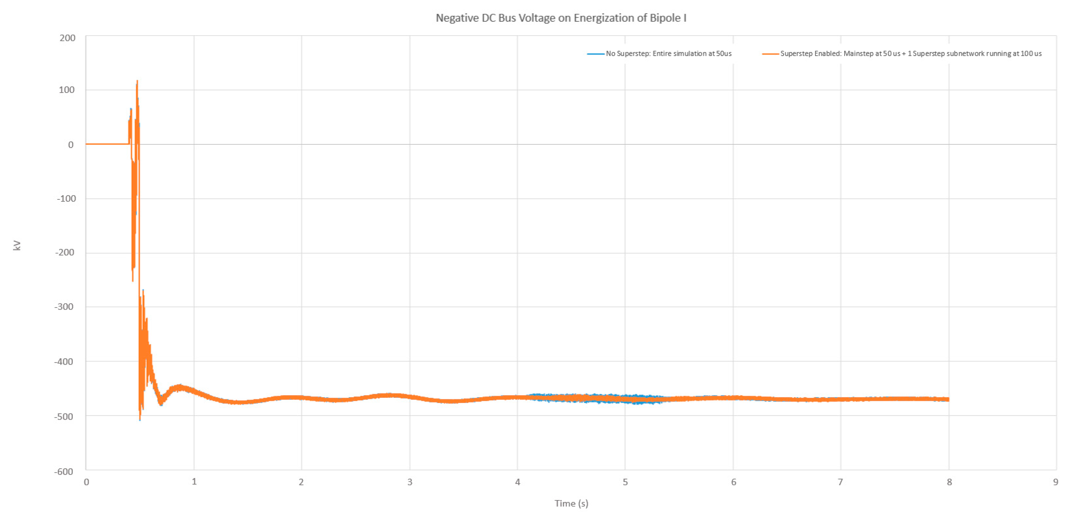
Figure 2 shows simulation results for a model which was developed to reflect the real-world network of a utility. The network includes over 200 three-phase buses, over fifty transmission lines, over twenty generators, an HVDC bipole (including DC line, converters, and switched filters) a static VAR compensator, and series capacitors. The network was first simulated using the main timestep environment to represent the entire network at a timestep of 50 µs (single-rate simulation). Then, a second simulation was run using the Superstep environment to simulate a portion of the network at two times the rate of the main timestep (multi-rate simulation). The results show the negative DC bus voltage upon energization of the first HVDC bipole.
The Pearson correlation coefficient for the signals shown in
Figure 2 is 0.999897361872902.
Table 1 below shows the Pearson correlation coefficient for several variables from the same simulation.
The ability to conveniently divide the network into subnetworks running at different timesteps on the central processor for numerically stable multi-rate simulation is an advancement for this technology category.
2.3. Predictive Switching Algorithm for Switched-Resistance Representation of Power Electronic Converters
Maintaining a full conductance matrix decomposition for a power electronic circuit in each and every timestep (~1 to 3 µs) is challenging from a processing perspective, but doing so allows each switching instance to be represented by a change in conductance at the switching point (sometimes called switched-resistance representation or resistive switching), which is advantageous in terms of simulation accuracy and flexibility. Due to the processing challenges, an alternative modelling approach [
9] was established and adopted by EMT tools in which discrete circuits using inductors and capacitors, referred to as L/C-associated discrete circuits, are used to emulate different switching states. Using L/C circuits instead of switched resistances means the network’s conductance matrix does not need to be decomposed in each timestep, significantly decreasing the active processing power required to simulate a given circuit. Using this method, the matrix decomposition can instead occur prior to running the simulation, resulting in computational savings, allowing for a much more complex power electronic circuit to be simulated with the given hardware. However, there are several technical challenges associated with the L/C switching approach. When a switching event occurs, the abrupt change from one representation to the other results in an artificial energy loss. This loss increases with switching frequency and effectively limits the frequency at which a converter model can be switched if modelled using the L/C approach. Beyond a ~3 kHz switching rate, the losses become too great for results to remain valid. This method also creates some noise on the output waveforms due to current oscillations within the discrete circuits, and requires that the R, L, and C parameters are selected properly by the user to ensure a well-damped transient response and a respectively large and small impedance for the L/C circuits over the entire bandwidth of interest.
To overcome these challenges, converters of interest can typically be simulated using resistive switching, but they must be decoupled from the surrounding power electronic circuit using a traveling wave transmission line model. This can introduce significant error into the simulation. A recent advancement for the RTDS Simulator allows for the user to circumvent both L/C switching and travelling-wave-interfaced converter models when simulating power electronic networks.
In order to enable the dynamic decomposition of the network matrix for power electronic circuits, an algorithm was developed which uses predictive switching to reliably determine the ON/OFF status of a converter’s switch devices before each simulation timestep [
10]. The algorithm allows for several fixed-topology converter models to be simulated in the Substep environment with resistive switching, without requiring an interfacing transmission line model. The following models are available for predictive switching at the time of writing:
Embedding these resistively-switched models into the fully decomposed Substep network rather than using an L/C modelling approach also has the benefit of eliminating fictitious power losses and oscillations. The reduction in oscillations achieved through the use of resistively-switched models for a neutral point clamped (NPC) converter over an L/C discrete circuit approach can be seen in
Figure 3. A high-frequency transient response is observed when the status of the switch is changed (and the representation is changed from an inductor to capacitor or vice versa). This response results from the energy loss created by the modelling approach. The reduction in power losses achieved through using the resistively-switched models, shown in
Table 2, results in a cleaner waveform and increases the switching frequency bandwidth over which a converter can be accurately represented. If necessary, power losses of the converter can be defined by the user during the parametrization process in order to reflect those of the physical device being modelled.
2.4. Co-Simulation with a Real-Time Simulator and PC-Based TSA Program
As mentioned in
Section 1 above, the several different power system modelling approaches that are popular today are variable in the level of detail they provide and the type of systems and dynamics they can reliably represent. Historically, phasor-based approaches such as transient stability analysis/assessment (TSA) have been widely used for system planning and operational studies. TSA simulations can run in real-time on a regular PC, as they offer phasors as an output and typically use a timestep of ¼ or ½ of the system cycle (i.e., 4 to 10 ms—in the order of 100 times greater than the timestep of a typical real-time EMT simulation) [
11]. The output of a TSA simulation lacks the wide frequency bandwidth offered by EMT solutions and the ability to represent subcycle phenomena associated with fast transients. However, the ability to represent larger systems with greater efficiency on a regular PC makes them ideal for many high-level power system studies.
The concept of co-simulation, in which the global representation of a given system can be achieved by composing simulations of its subsystems that are completed via different platforms or means, has been explored for some time. In a power systems context, the co-simulation of phasor-based TSA and EMT solutions could potentially be impactful for the user [
12]. For users who are looking to model large-scale networks with a reasonable level of detail but who have limited access to real-time simulation hardware, EMT-TSA co-simulation could reduce the hardware requirement while maintaining a high level of detail for a portion of the network. It is important to note that the level of detail available for the portion of the network represented via TSA will be lower. Any study completed via real-time EMT-TSA co-simulation should be judiciously selected for such a study based on technical requirements and the acceptable bandwidth of results for various areas of the network.
To benefit cases where the variance in timestep and output is acceptable and co-simulation is appropriate, a TSA co-simulation platform was developed for the RTDS Simulator. Called the TSAT-RTDS Interface (TRI), this tool provides an interface between the TSAT program (part of the DSATools™ suite of power systems analysis tools) and the real-time simulator. TSAT is familiar to many power system engineers and can represent over 5000 three-phase buses in real-time in addition to (and in parallel with) the portion of the network that is represented on the real-time simulator.
The TSAT-RTDS Interface is achieved via an FPGA that is installed in the PCIe slot of the user’s PC. This creates a continuous, synchronized real-time interface, meaning that TSAT and the real-time simulator exchange outputs at the end of every TSAT timestep. The software aspect of the tool was developed with the user in mind, and is able to automatically identify potential boundaries for partitioning between the EMT and TSA portions of the simulation and provide metrics that quantify their validity. The user may also manually select boundaries and have their validity assessed by the program. While the program is capable of such calculations, boundary selection is another aspect of co-simulation that must be judiciously approached by the user in order to ensure the technical validity of the simulation.
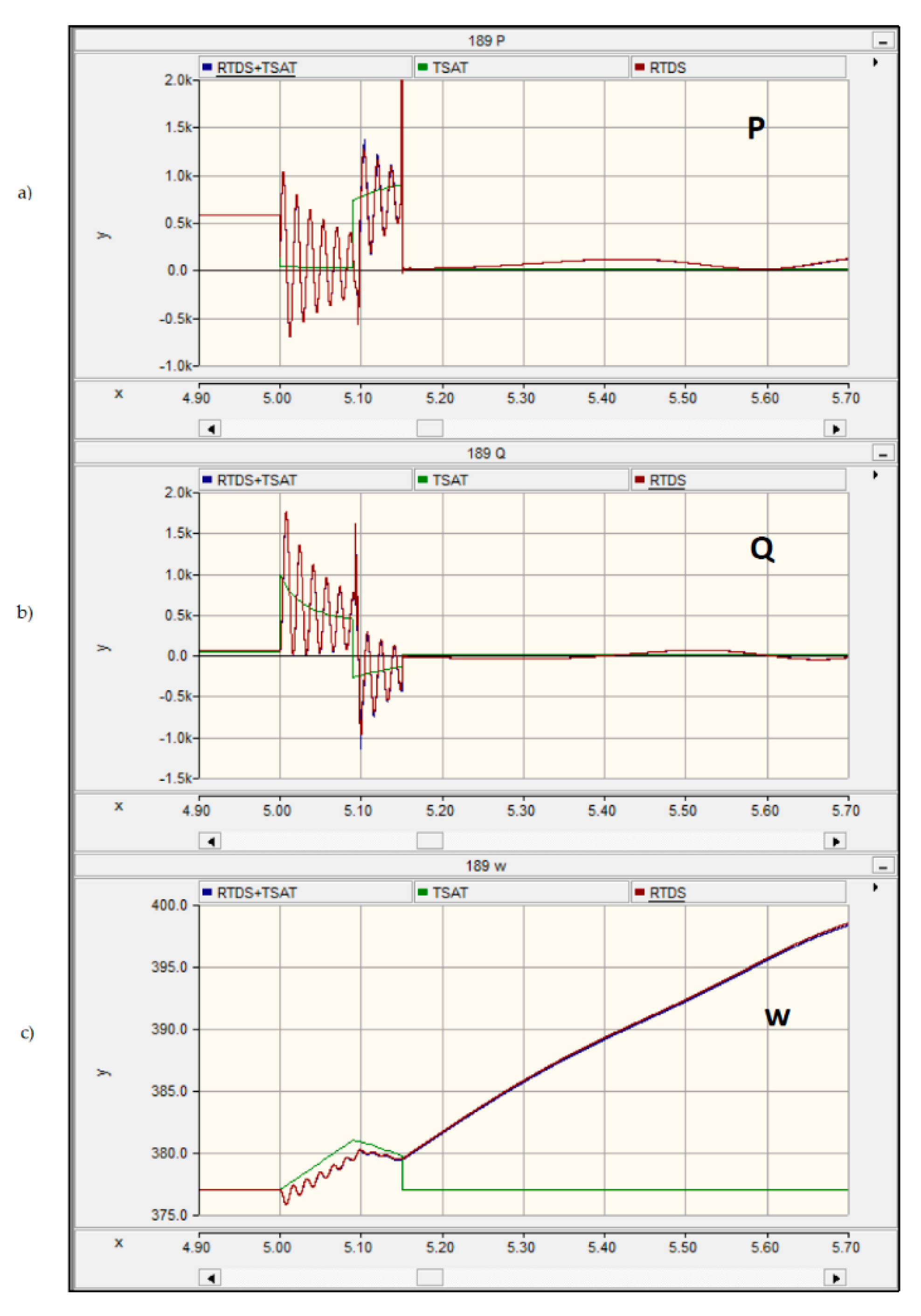
Figure 4 shows simulation results for the Illinois 200-Bus System [
13], which was divided for an EMT-TSA hybrid simulation. A 43-bus section was defined as the internal system to be modelled with the RTDS Simulator, with the remainder of the system modelled using TSAT [
14]. A fault was applied at a bus within the EMT-simulated area and a nearby generator—the largest one in the system—was tripped after a short delay, causing a large disturbance to the network. The results obtained for the hybrid simulation were compared with those from a full EMT simulation and those from a full TSA simulation. The results show the active power, reactive power, and speed of the generator closest to the disturbance.
In general, EMT-TSA co-simulation can be advantageous in its ability to analyze interactions between system-wide events on a large network and detailed device behavior, such as fault analysis in HVDC systems or sub-synchronous resonance studies. For users migrating to co-simulation from TSA-only simulation, another benefit is the ability to run detailed models that are not typically available in the TSA environment, including renewable energy components and HVDC or flexible alternating current transmission system (FACTS) devices. For those migrating to co-simulation from EMT-only simulation, the inclusion of a TSA-based representation of the larger surrounding system (rather than utilizing an infinite source in the real-time environment in order to reduce network matrix size) may increase the capability to accurately represent low-frequency oscillations (e.g., generator swings, inter-area dynamics, etc.).
As mentioned above in
Section 2.2, in situations when an EMT-TSA co-simulation is deemed inappropriate, using the Superstep feature of the RTDS Simulator may be an alternative solution.
2.5. Advancements in Real-Time Communication Protocol Implementation
The use of information exchange for power systems management and control is growing. The use of Ethernet-based communication protocols to develop a hardware-in-the-loop interface is now an established practice. Software models, built-in configuration tools, and hardware for streaming standard-compliant power system data in real time are all available for the RTDS Simulator [
15]. In order to allow users to test a wider variety of devices and schemes given industry advancements in automation, several recent developments have been made for the RTDS Simulator’s communication protocol facilities.
Existing publish/subscribe models for IEC 61850 Sampled Values (SV) and GOOSE Messaging protocols have been expanded to include support for routable versions (R-SV and R-GOOSE), which are popular for distribution automation applications [
16]. R-SV and R-GOOSE features are provided by IEC Technical Report 61850-90-5 [
17] for IEC 61850-9-2 SV and IEC 61850-8-1 GOOSE packets. When using R-SV and R-GOOSE, the user specifies a destination multicast IP address. The transport protocol used in these implementations is User Datagram Protocol (UDP).
The existing processor-based model for SV was also updated to include the output sample rates specified in IEC 61869-9 and the Chinese National Standard for merging units. These are shown in
Table 3.
Another advancement for real-time IEC 61850 Sampled Values implementation is the improvement of the existing FPGA-based model for SV streaming. In this case, FPGA-based hardware running the SV model is interfaced with the central processor via optical fiber. This model was updated for support from both the main timestep and Substep environments of the RTDS Simulator. Running the model at the Substep timestep (typically in the 1–3 µs range) allows for higher output sample rates than have previously been possible with a real-time simulator. The supported SV sample rates on the FPGA-based hardware are listed in
Table 4. Sampling rates as high as 96 and 250 kHz are available, supporting users interested in DC instrument transformer applications.
The implementation of Distributed Network Protocol 3 (DNP3) and IEC 60870-5-104 for the RTDS Simulator has also been improved. Rather than providing data exchange between the real-time simulator and a single external device, the user can now interface the simulator with up to four external devices simultaneously using a single instance of these protocol models. Using multiple instances of the models allows for connection to many external devices at once. The real-time simulator acts as a slave device connected to external masters. These protocols are commonly used by users for SCADA and distribution automation applications.
2.6. Digital Interface for Power-Hardware-in-the-Loop Simulation
Power-hardware-in-the-loop (PHIL) simulations have gained popularity due to their potential for analyzing and characterizing the response of physical converters, DERs, motors, and loads to a huge variety of system conditions in the safety of the lab [
18]. However, PHIL simulations can be challenging to implement in a technically sound manner. Developments for the RTDS Simulator in this area will improve the PHIL experience for users.
Establishing a valid and stable PHIL interface is not trivial, and selecting an appropriate four quadrant amplifier is a crucial step of the process, with several technical considerations including response times, slew rate, harmonic distortion, frequency resolution, and input/output ratings and impedances. Filtering is also a major technical consideration in order to reduce the impact of noise (introduced by voltage and current sensors, physical wiring, and electromagnetic coupling between devices) on the simulation. Any error introduced by noise can be amplified in the interface via positive feedback until hardware limits are exceeded. Filters for noise reduction introduce challenges of their own, including additional delays that may be added to the interface, so filter parameters should be determined carefully.
In order to reduce noise and delay and to simplify the PHIL interface, RTDS Technologies worked with four quadrant amplifier manufacturers to develop a digital interface between the real-time simulator and the amplifier. This eliminates the need for digital to analogue conversion in the interface via analogue input and output cards.
The digital interface was developed via Aurora, an open source high-speed serial protocol developed by Xilinx. Two different interfacing methods are currently available and are selected based on the manufacturer of the amplifier being used: a direct link between the real-time simulator and amplifier using an optical cable, or intermediary FPGA-based hardware which is programmed to buffer the Aurora data at the required rate for the amplifier.
The corresponding PHIL interfacing model within the simulation software also includes embedded voltage and current sources. This reduces loop delay and improves ease of use for PHIL applications.
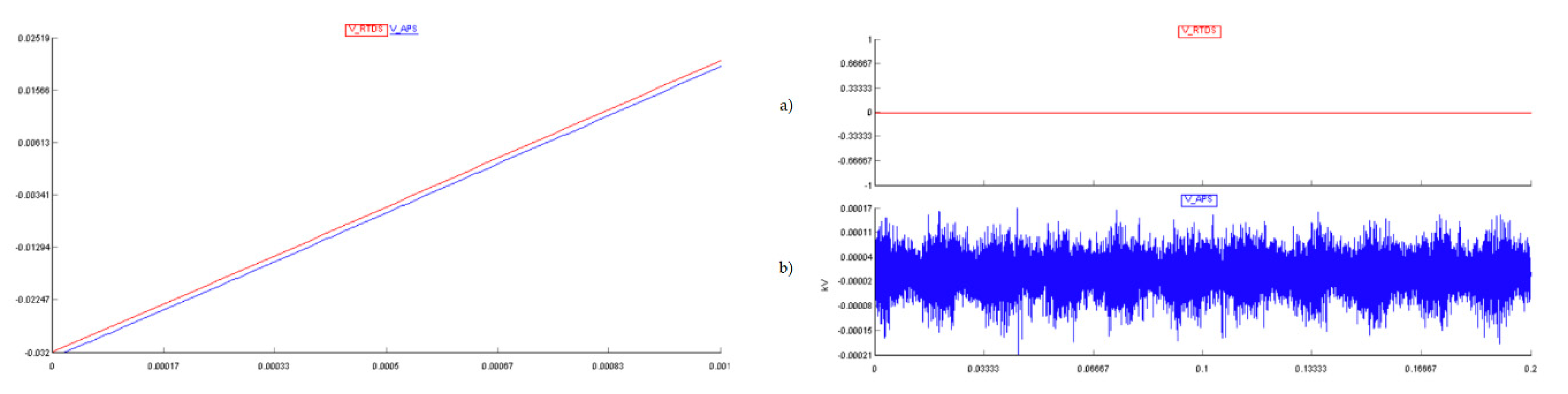
Figure 5 includes simulation results which show the loop delay and noise associated with the improved digital interface [
19]. Loop delay is case-dependent and is always less than one simulation timestep. In this example, the current is read back from the amplifier prior to the network solution calculation so that it can be used to calculate the new voltage to send out to the amplifier. The network solution therefore sees the amplifier as simply another component of the simulation. The low loop delay in the PHIL setup enables the user to mimic a fully digital simulation.
2.7. Enhanced Power System Component Models
2.7.1. Faulted Transformer Model Based on Terminal Duality Principle
A recent advancement in real-time power system component modelling is the development of an improved transformer model for the RTDS Simulator. This model is based on a terminal duality equivalent [
20] rather than the star equivalent [
21] which is frequently used in power systems simulation. The star equivalent, while providing accurate representation of the terminal conditions, is generally inaccurate in its representation of the physical transformer leakages via the inductance branches. The terminal duality model provides a more realistic representation of a transformer’s magnetic circuit. It includes a leakage branch representing the gap between the first winding and the transformer limb, providing a more accurate prediction of the maximum magnetization inrush current. It also considers the mutual coupling between branches, allowing for an improved representation of terminal conditions when compared to the star equivalent.
Internal faults, tap changers, or winding offsets may create asymmetrical conditions for the model. The short circuit reactance in these situations can be evaluated with relative accuracy as the terminal duality model decomposes the leakage flux into both axial and transverse components.
This model introduces a new degree of accuracy in real-time transformer modelling, providing improved results for the transient behavior of transformers. This will in turn increase the accuracy of closed-loop tests performed on transformer protection devices via a real-time simulator.
2.7.2. Faulted Phase Domain Synchronous Machine
A phase domain synchronous machine (PDSM) model capable of modelling internal faults has also been developed for the RTDS Simulator [
22]. The model allows for access (the ability to connect components) to all phases of the stator terminals, the machine neutral, and up to two points in each phase of the field winding. This allows users to apply turn-to-turn faults on the stator and on the field winding, faults between phases, and faults between phases and the field winding. The model is also appropriate for the testing of 100% stator-ground fault detection in protective devices.
With the phase domain approach, new machine inductance values are calculated every timestep in order to represent possible changes in rotor position and saturation. The self and mutual inductances of the windings are calculated as functions of rotor position and saturation to represent internal faults. The machine’s differential equations are solved as an embedded part of the simulation’s network solution. This embedded phase domain approach shows better performance in terms of numerical stability when compared to the approach of dq0-based models interfaced to the network (used traditionally by transient simulation programs) [
23]. The interfacing delays inherent with these conventional models can cause issues with numerical stability in the presence of other interfaced components in real time.
The PDSM model allows the user to simulate the following fault scenarios and place the fault anywhere between 1% and 99% of the windings:
Turn-to-turn faults in individual phases
Turn-to-ground faults in individual phases
Phase-to-phase faults
Phase-to-ground faults
Turn-to-turn faults in the field winding
Turn-to-ground faults in the field winding
Series faults in the stator and field windings
Inherent imbalance in the windings
This model can be used to test generator protection schemes under an unprecedented range of internal fault conditions.
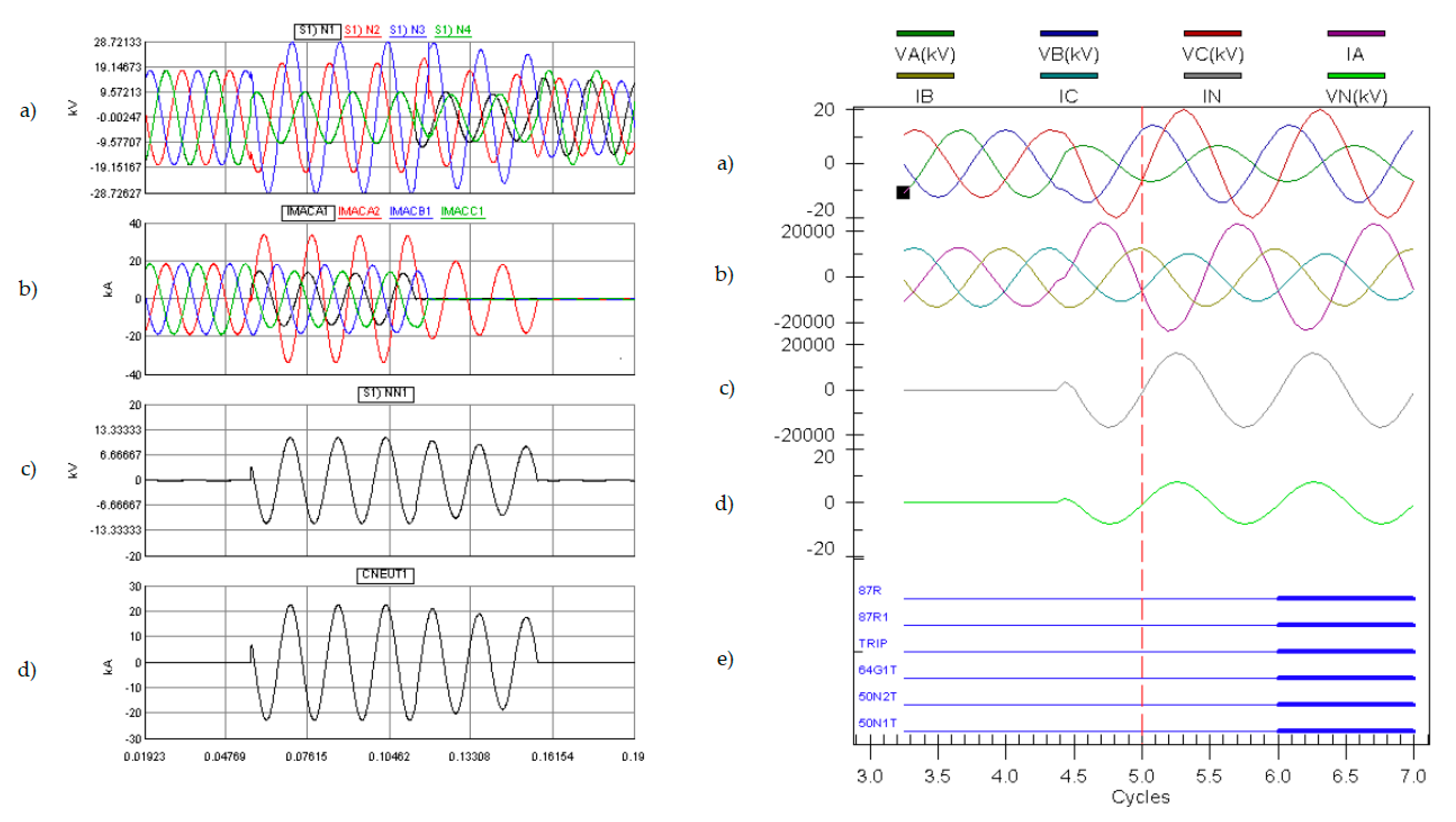
Figure 6 shows the results of testing a commercial relay by simulating a stator-ground fault. The plot on the left shows the simulation results, including terminal voltages, machine currents, and neutral voltage and current. The plot on the right shows the relay’s recorded events, indicating that the phase differential (87), neutral overvoltage (64G1), and neutral overcurrent (50N) elements were activated.
2.7.3. Substep Frequency-Dependent Transmission Line
The emergence of travelling wave-based relays is a recent advancement in the field of power systems protection. The protective devices incorporating these techniques trip securely in as fast as a few ms, record events in the MHz sampling rate range, and locate faults with relatively high accuracy [
24]. In order to accurately test such a relay in a hardware-in-the-loop situation, a corresponding advancement must be made in the real-time modelling library.
A frequency-dependent phase domain (FDPD) transmission line model has long been available for the RTDS Simulator in the main timestep environment. This model uses an established method known as the universal line model [
25] to represent the line and its frequency-dependent properties without the need to compute a modal transformation matrix as is necessary with a frequency-dependent modal domain model [
26]. The phase domain model has also been shown to be more accurate than the modal domain model when modelling non-transposed line segments [
27]. For the FDPD model, curve-fitting techniques are used to represent the frequency dependence (including damping) of the line’s characteristic admittance and propagation constant. This model is more processor-intensive than both the common modal domain Bergeron transmission line model (which does not represent frequency dependence) and the frequency-dependent modal domain model.
In order to accurately test travelling-wave-based protection, the Bergeron model cannot be used, as it is a single-frequency model and cannot accurately represent travelling waves which contain a wide range of frequencies. A frequency-dependent line model must be used to properly represent the full bandwidth of behavior of the travelling wave. However, the typical main timestep (30 to 60 µs) is not sufficient for testing these protection algorithms, which are based on a relay sampling frequency in the MHz range. To overcome this challenge, a frequency-dependent transmission line model (based on the universal model) was developed for use in the Substep environment. This Substep FDPD model, capable of running in real time in the 2 µs timestep range, was used to test the first-ever travelling-wave relays used developed for primary protection of a high-voltage line [
28]. It should be noted that an FDPD line model running at timesteps appropriate for travelling-wave relay testing is also available for the RTDS Simulator via FPGA. In this case, FPGA-based hardware running the frequency-dependent line model is interfaced with the central processor via optical fiber.
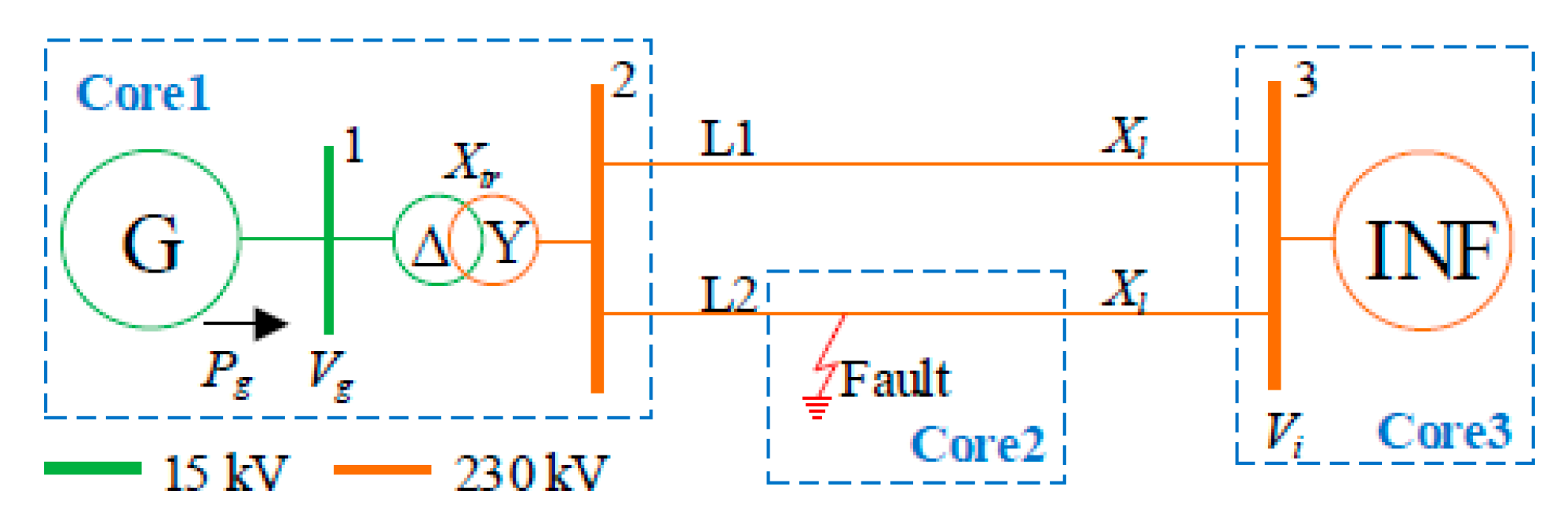
Figure 7 shows a simple system model that was used for testing travelling-wave relays to demonstrate the Substep frequency-dependent transmission line model [
29]. A generator is connected to an infinite bus via a transformer and double-circuit transmission line. The model was run on the central processor at a 3.1 µs real-time timestep for this particular example. Timesteps as low as 1.4 µs have been used to test travelling-wave relays using the RTDS Simulator.
A permanent three-phase to ground faults was applied on L2 close to the generator side.
Figure 8 includes test results from the real-time simulator (top) and relay recording (bottom). The simulation results, which show the three-phase currents on L2 at Bus 3 (from the real-time simulation running at 3.1 µs), include validation against a non-real-time simulation program in which the model was run with a 0.1 µs timestep. The relay results show the fault inception point, current variable activity, and trip signal point. The fault detection time of the relays in this test is around 1.1 ms.
3. Discussion
Real-time simulators are under continual development by their manufacturers in order to remain reflective of the modern power system and industry practices. This paper describes a non-exhaustive selection of recent developments rolled out by a particular manufacturer: RTDS Technologies Inc.
Many of the advancements detailed in this paper were enabled by growth in the high-performance processing space and the emerging availability of high-end processors with an open design architecture (e.g., the OpenPOWER™ Foundation). Others were initiated or supported by developer participation in power industry working groups and study committees.
It should also be noted that several of the advancements in this paper were motivated by needs identified by users of the real-time simulator in question. In this sense, the advancement of this technology is partially anticipatory and partially responsive. Users of real-time simulators are utilities, consulting companies, universities, research institutions, or manufacturers of power system protection and control equipment. Technical expertise combined with a high degree of control over both the hardware and the software aspects of this technology are necessary to deliver reliable and accurate solutions to these users.


