Article

RANS Simulation of the Effect of Pulse Form on Fluid Flow and Convective Heat Transfer in an Intermittent Round Jet Impingement

Laboratory of Thermal and Gas Dynamics, Kutateladze Institute of Thermophysics, Siberian Branch of Russian Academy of Sciences, Acad. Lavrent’ev Avenue 1, 630090 Novosibirsk, Russia
*
Author to whom correspondence should be addressed.
Energies 2020, 13(15), 4025; https://doi.org/10.3390/en13154025
Submission received: 11 July 2020 / Revised: 31 July 2020 / Accepted: 31 July 2020 / Published: 4 August 2020
(This article belongs to the Special Issue Enhancement of Heat Transfer in Power Plants)

Abstract

:
The of effect pulse form (rectangular, sinusoidal and triangular) on the fluid flow and heat transfer of an intermittent jet impingement was studied numerically. It was shown in a non-steady-state jet, both an increase and decrease in heat transfer are possible compared with steady-state jet for all investigated pulse forms. For small distances between the pipe edge and obstacle (H/D ≤ 6) in the pulsed jet, heat transfer around the stagnation point increases with increasing pulse frequency, while for H/D > 8 an increase in frequency causes a heat transfer decrease. A growth in the Reynolds number causes a decrease in heat transfer, and data for all frequencies approach the steady-state flow regime. The numerical model is compared with the experimental results. Satisfactory agreement on the influence of the form and frequency of pulses on heat transfer for the pulsed jet on the obstacle surface is obtained.

Graphical Abstract

1. Introduction

Many works deal with the study of aerodynamics and heat transfer in turbulent impinging jets. High values of heat and mass transfer are observed around the stagnation point at the interaction of a jet with an obstacle surface. Such studies are used in many practical applications (cooling various power equipment, turbine blades, coating, drying, and hardening various materials, etc.). Detailed theoretical and numerical studies of the heat and mass transfer in steady-state jets impingements have been performed. The main advantages and disadvantages of such flows can be found in a number of comprehensive monographs [1,2] and reviews [3,4,5,6,7,8].
A pulsed (non-steady-state) impinging jets are one of the methods for active control of the fluid flow and heat transfer characteristics. A lot of experimental and numerical papers over the past 30 years were performed. It was found that the main features of pulsed impinging jets are the thinner dynamic and thermal boundary layers compared with steady-state one, a turbulence production, and the flow instability. Data from various authors are often contradictory. Heat transfer enhancement, decrease or absence of influence were revealed. The increase in heat transfer can vary from 10 to 100% around the stagnation point and up to 50% in the wall jet development area. Heat transfer reduction can reach 30% along the impinging surface.
The experimental study of an intermittent impinging water jet was obtained in [9,10]. The decrease in heat transfer by about 20% in the region of low Strouhal numbers (St = 0.012–0.14) and to an increase of up to 50% at St = 0.15–0.26. Heat transfer was studied experimentally in [11] in the jet Reynolds numbers Re = (4–40) × 103 for frequencies f = 0–200 Hz. Heat transfer suppression up to 20% was obtained in comparison with steady flow in the entire frequency range. It was shown in [12] that, in addition to the pulse frequency f, heat transfer is influenced by the duty cycle parameter: the ratio between pulse on-time ton and total cycle time tc: DC = ton/(ton + toff) (see Figure 1a). A new type of self-excited precession jet nozzle was designed in [13], and this device has little effect on heat transfer. Measurements of the effect of pulse frequency and amplitude were carried out in [14]. The authors of [14] also observed heat transfer increase and decrease in a pulsed impinging jet.
The pulse form (rectangular, triangular, sinusoidal, and their combinations) (see Figure 1b) also has a noticeable effect on the heat transfer intensity over the entire length of the surface (see [15,16,17,18,19]). An experimental study of the flow structure and heat transfer in a pulsed impinging jet on a smooth impact surface and in the presence of a ring mounted on the obstacle surface was performed in [15,16]. The authors [15] suggested that the effect of a synthetic impinging jet can be initiated when the frequency of pulses imposed on the jet coincides with the natural frequency of the nozzle. A significantly higher average flow rate was achieved due to the strong effect of the synthetic jet. The presence of a ring causes a strong suppression of heat transfer in pulsed impinging jet (up to 80%) in comparison with a smooth surface. In experimental works [15,16,17,19], the influence of the pulse forms on heat transfer for low frequencies (f ≤ 40 Hz) was measured. The maximum heat transfer enhancement, up to 30% in comparison to steady-state flow, was achieved using a rectangular pulse form, while other pulses shapes give similar values for the heat transfer increase (up to 15%).
The experimental study of heat transfer was carried out in [18] for 1 ≤ H/D ≤ 6, 6000 ≤ Re ≤ 14 000, and 9 ≤ f ≤ 55 Hz. The interaction of a pulsed jet with an obstacle surface differs significantly both around the stagnation point (r/D ≤ 1) and in the wall jet development zone (r/D ≥ 3). Heat transfer intensification was higher in the wall jet zone than near the stagnation point. An experimental and numerical study of an intermittent jet impingement in the presence of a confined upper wall was carried out in [20]. The experiments were carried out in the following range of parameters: 2 ≤ H/D ≤ 10, 5000 ≤ Re ≤ 15000, and 5 ≤ f ≤ 40 Hz. A special transition chamber was installed between the nozzle edge and the upper wall. The numerical simulations were carried out using the FLUENT package. The heat transfer was higher in the case of its presence, than that in the case of its absence due to a change in the profile shape of the velocity of pulsed jet.
The numerical studies of flow patterns and heat transfer in pulsed jet impingement were carried out in [21,22,23,24,25]. The RANS predictions were performed on the commercial CFD package FLUENT in a slot impinging jet in the presence of a confined upper wall with varying pulse frequencies. Heat transfer intensification was shown due to an increase in the flow velocity in the pulsed regime during the pulse and in the presence of the zone of intensive flow recirculation. In [22], the heat transfer was studied in a pulsed slot jet impingement.
The authors of [23,25] numerically studied heat transfer in a pulsed impinging jet using the RANS approach and the Reynolds stress transport model. In the region of small distances between the pipe outlet and impinging surface (H/D ≤ 6) in the pulsed jet, heat transfer at the stagnation point increases with increasing pulse frequency, while for H/D > 8, an increase in frequency causes a decrease in heat transfer. The authors of [24] numerically studied the heat transfer in a jet impingement onto a spherical surface. The simulation was carried out using the commercial package FLUENT. The RANS approach and various modifications of isotropic turbulence models were used. The heat transfer suppression is obtained up to 10%, and its increase is up to 40% [24]. For rectangular pulses, the heat transfer enhancement is higher than for the sinusoidal pulses [24].
The experimental and computational works presented in the literature answer only a part of the questions. Therefore, further detailed studies are necessary to accumulate new results of heat transfer in impinging intermittent jet. This work is aimed at the numerical study of the influence of pulse form (rectangular, triangular, and sinusoidal) on heat transfer in an axisymmetric non-steady-state impinging jet. This work is a continuation of [23,25], where heat transfer was studied in a pulsed impinging jet only for rectangular pulses. This study may be of interest to scientists and engineers dealing with problems of heat and mass transfer augmentation in power equipment.

2. Mathematical Model and Numerical Realization

The fluid flow and heat transfer of an intermittent axisymmetric flow, the non-steady-state Reynolds-averaged Navier–Stokes (RANS) equations system [23,25] is employed. A schematic of impinging jet development is shown in Figure 2. To describe the gas turbulence, the model of Reynolds stress transport [26] is used. It includes a set of equations for second moments u i u j and the equation of dissipation of turbulent kinetic energy ε. A numerical solution is obtained using the finite volume method on a staggered grid. The QUICK procedure of second-order accuracy is employed for the convective terms of differential equations. The central differences of the second order of accuracy are used for diffusion terms. The pressure field is corrected using the finite-volume SIMPLEC procedure.
A computational non-uniform grid in both axial and radial directions was applied with a high-resolution impinging surface and in the jet axis zone. The computational domain was a cylinder with a size of 10 pipe diameters and height H. The first computational node from the wall was at a distance y+ = yU*/ν = 0.3–0.5, where y is the distance normal from the surface and U* is the friction velocity. At least 10 control volumes were generated to resolve the mean velocity field and turbulence quantities in the viscosity-affected near-wall region (y+ < 10). Grid sensitivity studies were carried out to determine the optimum grid resolution that gives the mesh-independent solution. For all the numerical computations, a basic grid with 200 × 256 = 5.12 × 10⁴ control volumes (CVs) along the axial and radial directions was employed. Grid convergence was verified for three grid sizes, 100 × 128 = 1.28 × 10⁴, 200 × 256, and 400 × 400 = 1.6 × 10⁴ CVs. The difference in the Nusselt number is up to 1%. The time step was ∆t = 10−5 s.
At the pipe outlet cross-section, the results of preliminary simulations of a single-phase flow in the pipe with length x/D = 75 were used for the gas phase. Thus, in the pipe outlet cross-section, there was fully developed turbulent gas flow. Symmetry conditions were set on the jet axis. Impenetrable and adherence conditions were set on the wall. The boundary conditions at the external boundary of the computational domain were set in the form of zero values of the derived parameters in the direction parallel to the impact surface.

3. Numerical Results and Its Discussion

All simulations were performed for air at atmospheric pressure. The pipe outlet I.D. was D = 20 mm and the distance to the obstacle was H/D = 1–10 (see Figure 2 and Figure 3). The mean-mass time-averaged gas flow velocity at the pipe outlet cross-section, both for steady-state and pulsed flow regimes, varied in the Um1 = 5–50 m/s range, and the jet Reynolds number, Re = DUm1/ν = (1–8) × 104. The wall temperature was constant at TW = 373 K. The gas temperature at the pipe edge was T1 = Te = 293 K, and it coincides with the temperature in the ambient medium. The predictions were performed for the pulse frequencies f = 0–300 Hz for all pulse forms. The Strouhal number, determined by the pipe diameter, varied in the range St = fD/Um1 = 10−5–0.5. All computations were carried out at an equality of time-averaged mass flow rate for the pulsed and steady-state impinging jets.

3.1. Fluid Flow Characteristics
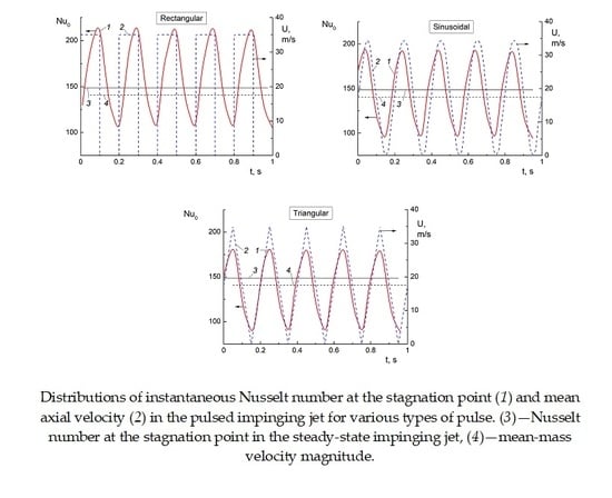
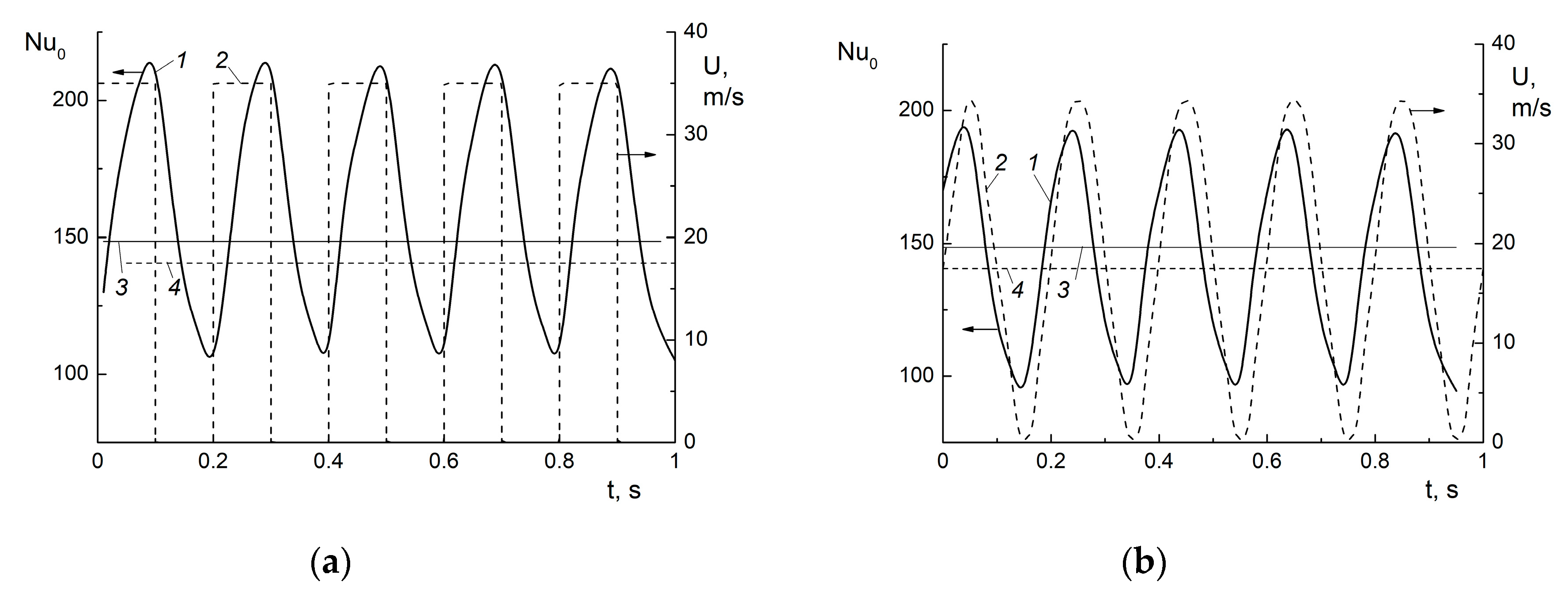
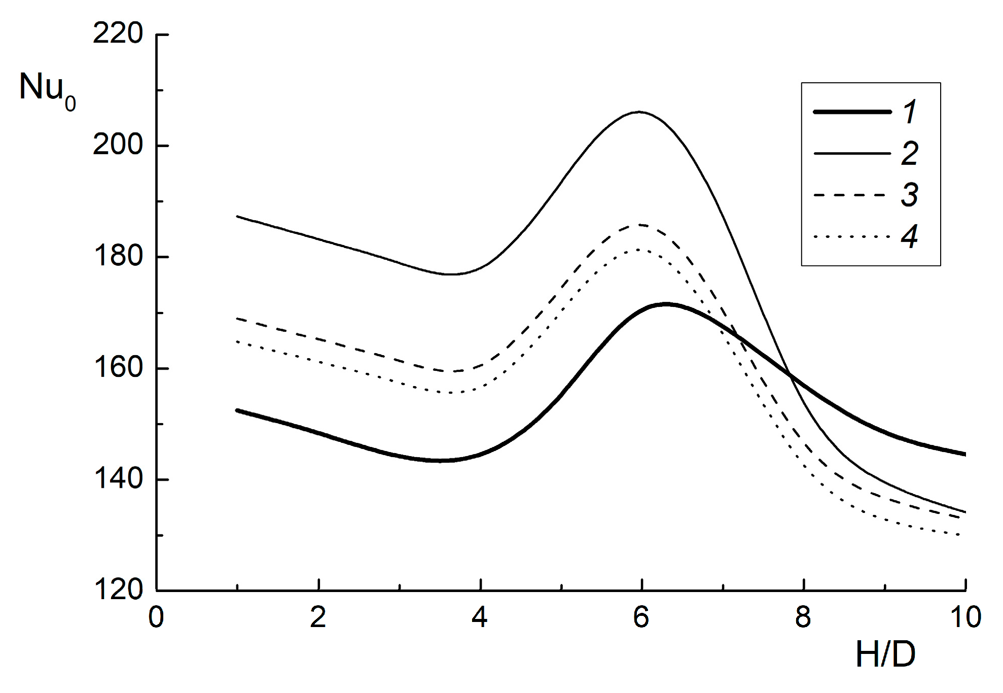
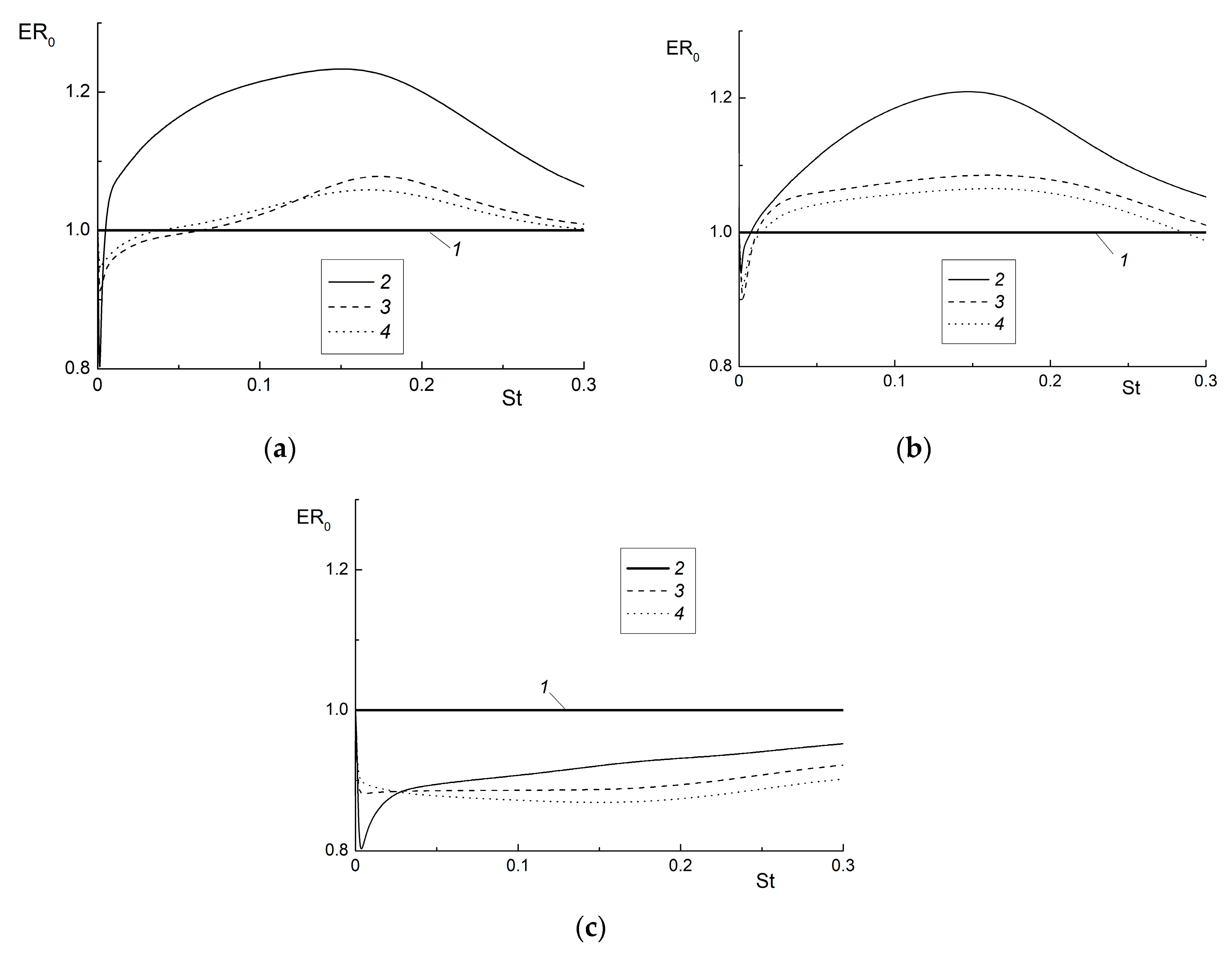
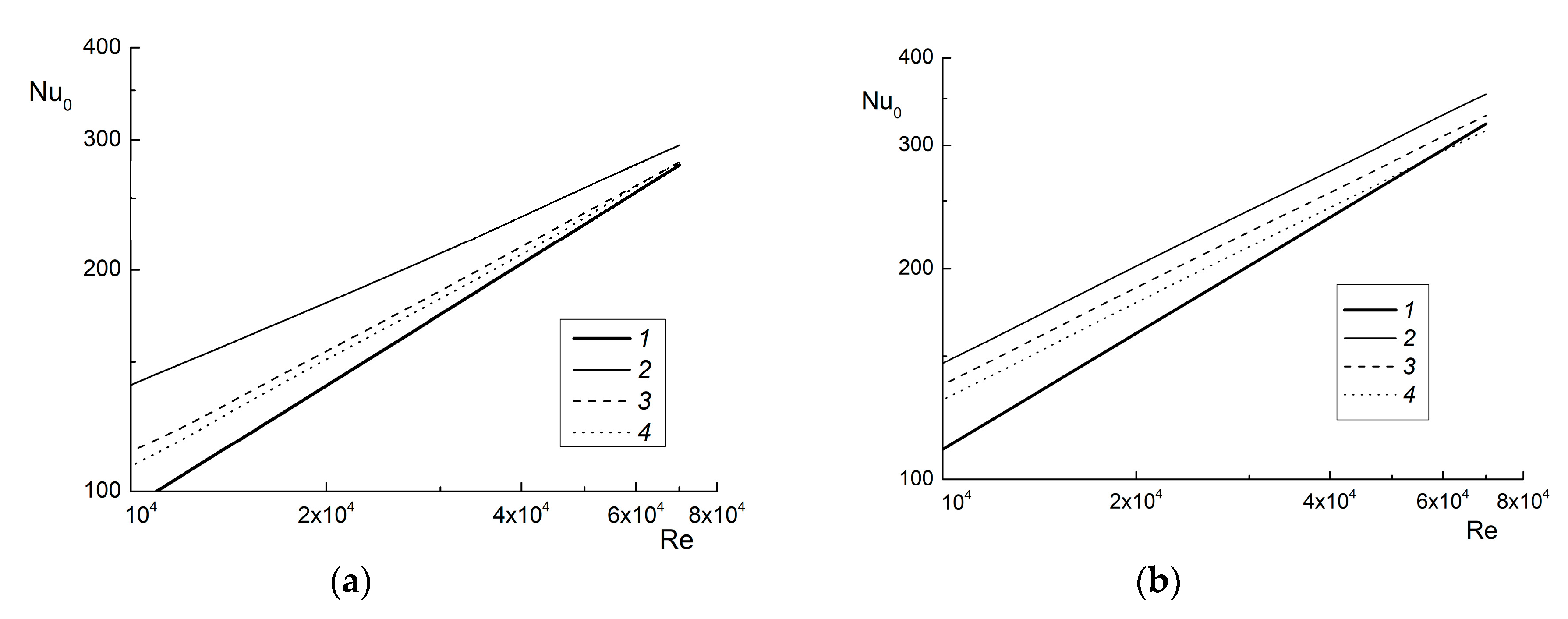
The transverse distributions of the total fluid velocity (a), turbulent kinetic energy (b) and temperature (c) at r/D = 1 are shown in Figure 4. Here U = ( U 2 + V 2 ) 0.5 is the mean total gas velocity and U m 1 S t is the mean-mass velocity of the steady-state impinging jet in the inlet cross-section and y is the distance normal to the wall. Lines 1 represent simulations for the steady-state impinging jet. The results are given for time t = 0.5tc (see Figure 1a), i.e., at the moment when the fluid velocity is maximum for the case of a rectangular pulse (immediately before the flow-off) and at the time t = 0.5tc = π for the sinusoidal and triangular pulses (see Figure 1b).
The mean total velocity U and turbulence of the intermittent impinging jet for all investigated pulse forms at t = 0.5tc (lines 2–4) were higher than the corresponding values for a steady-state impinging jet (line 1) (see Figure 4a,b). Here, U and V are the mean axial and radial velocity components. The maximum growth was obtained for a rectangular pulse (line 2); the minimum growth was obtained for a triangular pulse (line 4). The turbulence of the carrier fluid flow was determined by the formula for an axisymmetric flow:
k = u i u i / 2 = ( u i 2 + v i 2 + w i 2 ) / 2 ( u i 2 + 2 v i 2 ) / 2
The gas temperature in the pulsed flow for all pulse forms has a smaller value than that for a stationary flow Θ = ( T T W ) / ( T 1 T W ) (see Figure 4c). This explains the increase in heat transfer in the non-stationary impinging jet in comparison with the steady-state impinging jet. The minimal temperature is obtained for rectangular pulses (line 2), and the highest was obtained for triangular pulses (line 4).

3.2. Heat Transfer

The distributions of the axial mean velocity (dashed line) and the Nusselt number Nu0 at the stagnation point (continuous lines) are shown in Figure 5 for rectangular (a), sinusoidal (b) and triangular (c) pulse forms. Data for five consecutive cycles (f = 5 Hz) with equal average mass flow rates in stationary and pulsed flows over time are also presented in Figure 5. The Nusselt number value for steady-state flow was Nu0 = 150.3 for the distance H/D = 2. For all the studied pulse forms, a change in the Nusselt number Nu0 in time was harmonic. Local heat transfer maxima and minima were at the end of the flow-on time and at the moment before the start of a new pulse, respectively. The minimum heat transfer value at the frequency f = 5 Hz did not vanish, but is about two-thirds of the magnitude in a steady-state impinging jet. This indicates that the inertia of the jet and the thin boundary layer developed on the wall surface. The maximum heat transfer value was achieved for the rectangular pulse form, and the minimum value was achieved for the triangular one. The heat transfer intensity for the sinusoidal form was close in magnitude of the triangular form. This is in qualitative agreement with the measurement data of [15,16]. The triangular and sinusoidal pulse forms have a shift in the Nusselt maximum position relative to the rectangular pulse. The maximum velocity and maximum of heat transfer rate for a rectangular form of pulse is obtained at t = 0.5tc, while for the triangular and sinusoidal forms, the maxima of velocity and heat transfer observe earlier, at t = 0.25tc.
The time-averaged Nusselt numbers at the stagnation point for various pulse forms are shown in Figure 6. Here Nu 0 = 1 T C 0 T C Nu 0 ( t ) d t is the time-averaged Nusselt number, TC is the averaging time (at least 5 periods). The time-averaged gas mass flow rates at the pipe outlet for the data shown in Figure 6 is unchanged. Curve 1 corresponds to the stationary impinging jet. The predictions were performed at f = 150 Hz (St = 0.17). In our earlier simulations [25], it was shown that for rectangular pulses at such a pulse frequency and Reynolds number of the flow, the maximum value of heat transfer is obtained around the stagnation point.
The distance between pipe outlet and the impinging surface has a significant influence on heat transfer in an impinging pulsed jet, and the same trends were obtained for steady-state impinging jets [1,2,3]. The dependence of heat transfer intensity on the nozzle-to-plate distance for all pulse forms has a qualitatively similar form. The heat transfer suppresses at small distances to the obstacle (3 < H/D < 4). The maximum value of heat transfer at the stagnation point is achieved at the distances H/D ≈ 6. This was observed both in the stationary and non-steady-state cases and for all three pulse forms. This distance is roughly equal to the length of the potential core of the jet, and a similar picture is noted in [1,3,4] for a steady-state impinging jet. The heat transfer decreases again due to a decrease in velocity on the axis of the jet with a further increase in the nozzle-to-plate distance. For H/D < 7, the heat transfer coefficient in the pulsed impinging jet significantly exceeds the corresponding value for steady-state flow for all pulse forms. The magnitude of heat transfer augmentation is up to 30%, and it was observed for rectangular pulses at relatively small distances H/D < 2. The suppression of heat transfer in pulsed jet impingement becomes noticeable in comparison with a steady-state jet at large distances from the obstacle (H/D > 8).
The effect of the pulse form on heat transfer enhancement ratios of the impinging jet ER0 = Nu0, p/Nu0, st is shown in Figure 7. Here Nu0, p and Nu0, st are the heat transfer in non-stationary and steady-state impinging jets, respectively. The Nusselt number value at the stagnation point for steady-state flow is Nu0, st = 150.3 at distance H/D = 2; Nu0, st =174.5 at H/D = 6; and Nu0, st =144.6 at H/D = 10. The heat transfer intensification is ~20% for a rectangular pulse form and ~10% for sinusoidal and triangular pulse forms. The heat transfer reduction is ~20% for a rectangular pulse form (f = 1–3 Hz and St ≤ 3 × 10⁻³) and ~10% for sinusoidal and triangular pulse forms (almost in all the studied ranges of pulse frequencies).
Both heat transfer intensification and its suppression can be obtained in an impinging jet in comparison to steady-state flow for all studied pulse forms and pulse frequency values. For the very low frequencies (f ≤ 3 Hz and St ≤ 3 × 10⁻³), all the curves for all pulse forms studied in this work have a characteristic minimum (see Table 1). This is consistent with the measurement data of [15,16] and our calculations for rectangular pulses [23,25]. At low frequencies, the predicted values approach the quasi-stationary limit, which suggests the possibility of using a simpler method [23] to estimate the level of heat transfer. The heat transfer enhancement ratio also increases for all pulse forms with a further increase in the Strouhal number (pulse frequency). The maximum increase in heat transfer in the pulsed flow was obtained in the Strouhal number range St = 0.17 (f = 150 Hz) for all types of pulse forms. Furthermore, a decrease in the heat transfer intensity at higher pulse frequencies (St ≥ 0.2) is also typical. This can be explained by the fact that at short pulses, the surface does not have time to restore due to the pulses closely following each other, which causes an increase in the thickness of the thermal boundary layer.
The distributions of maximal heat transfer at stagnation point vs. jet Reynolds numbers is shown in Figure 8 for H/D = 2 (a) and 6 (b). Line 1 here corresponds to a steady-state impinging jet (f = 0 Hz), which is described by Nu0 ~ Re0.57. The exponent n varies in the range n = 0.55–0.68 [1,27,28] and n = 0.5–0.62 [29,30,31], which is quite close to the results this work. The heat transfer in the pulsed jet is higher than that one for the steady-state impinging jet.
The radial distributions of local heat transfer are shown in Figure 9 for all three pulse forms at a frequency of f = 150 Hz and for three different distances from the jet stagnation point. The heat transfer intensification occurs along the length of the obstacle for H/D = 2 and 6 (see Figure 9a,b) and heat transfer suppression along the entire length of the surface is characteristic is predicted for H/D = 10 (see Figure 9c). An increase in heat transfer in the flow stagnation region r/D <1 is obtained. This is explained by significantly smaller thermal boundary layer thickness in the pulsed jet in comparison with stationary jet impingement. The second heat transfer maximum at distance r/D ≈ 2 at H/D = 2 is observed in pulsed impinging jet. The two local maxima in heat transfer observed are explained by the small distance between the cooled surface and the pipe edge [1,2,4]. We note that the main increase in heat transfer is predicted in the region of r/D < 2, the flow stagnation region, and the gradient zone. Downstream for r/D > 3 (the wall jet propagation region), heat transfer in the pulsed impinging jet decreases markedly. On the whole, the distribution of the heat transfer along the radial coordinate is in qualitative agreement with those for steady-state impinging jets [1,2,3].

4. Comparison with the Experimental Results in the Pulsed Impinging Jet

The experiments of [15,16] are used for comparison with the results of authors’ numerical simulations. The experiments are carried out for an axisymmetric impinging pulsed jet at Re = 7500, f = 0–40 Hz, St = (0.2–7.6) × 10−2, qW = 420 W/m2, DC = 0.5, H/D = 3 [16] and 6 [15]. Distributions of the heat transfer enhancement ratio (HTER) ER0 = Nu0, p/Nu0, st is shown in Figure 10. All predicted curves and experimental results [15] have a characteristic minimum for low-frequencies (f = 1–2 Hz and St = (2–4) × 10−3). The value of heat transfer intensification increases as the Strouhal number growth. Heat transfer suppression is observed for a rectangular pulse for the frequencies (f ≤ 5 Hz and St = 0.01). Heat transfer suppression is observed for larger values of frequencies (f ≤ 20 Hz and St = 0.02) for the triangular and sinusoidal pulses. It is characteristic for both the experiments in [15] and our predictions. The maximum increase in heat transfer is 25% for the rectangular pulse form, and for the triangular and sinusoidal forms, this increase is up to 10% for our simulations and 5% for the measurements of [15]. A satisfactory agreement between our numerical results and the experiments of [15] for all studied range of frequencies and pulse forms.
A radial change in HTER is shown in Figure 11 for three pulse forms and for f = 1.25 Hz. The heat transfer suppression in a quasi-steady-state flow is characteristic for all pulse forms. The heat transfer reduction is noted in the axial zone and this value is 12% for the sinusoidal pulses. Heat transfer in the pulsed impinging jet increases for all pulse forms at distance along the surface radius. Only rectangular pulses are characterized by both deterioration of heat transfer up to 10% (r/D ≤ 9) and its increase (up to 5% in our predictions and up to 10% according to the experiments of [16]) for r/D > 9.
The maximal effect on heat transfer in intermittent impinging jet is obtained for rectangular pulses, according to the authors’ numerical analysis and the measurements of [15,16]. Therefore, a detailed comparison with the experimental results of [16] on the influence of the pulse frequency on heat transfer along the target is shown in Figure 12. The increase in heat transfer along the obstacle is revealed in the pulsed impinging jet at low frequencies f = 5 Hz. The maximum position of heat transfer is shifted from the stagnation point downstream in pulsed jet impingement. The heat transfer maximum is obtained at r/D = 16–18 for f = 5 Hz, and for frequency f = 40 Hz, the heat transfer maximum is at r/D = 4–5. This is obtained both in the measurements of [16] and in our numerical simulations. The most probable reason for this is the process of formation and motion of large-scale vortices in a non-steady-state impinging jet.

5. Conclusions

The effect of the pulse form on heat transfer in a pulsed impinging jet is studied numerically using the unsteady RANS model and the second-moment closure. In the intermittent impinging jet, both an increase and suppression of heat transfer are possible in comparison with a steady-state jet for all studied pulse forms. The heat transfer at the stagnation point increases with increasing pulse frequency in the region of relatively small distances between the pipe edge and the obstacle (H/D ≤ 6). The heat transfer decreases with the increase in pulse frequencies for large distances H/D > 8. An increase in the Reynolds number weakens the effect of heat transfer intensification, and the data for all frequencies approach the stationary flow regime. A comparison with the experimental data by other authors is performed and satisfactory agreement on the influence of the form and pulse frequencies on heat transfer in an intermittent impinging jet surface is obtained.

Author Contributions

M.A.P. and V.I.T. developed the numerical model and performed the numerical simulations presented in the paper. All authors have read and agreed to the published version of the manuscript.

Funding

This work was supported by the Russian Scientific Foundation (Project No. 19-79-30075) and the turbulence model for the single-phase flow was developed in the framework of the program AAAA-A17-117030310010-9.

Conflicts of Interest

The authors declare that they have no known competing financial interests or personal relationships that could have appeared to influence the work reported in this paper.

Nomenclature

CPspecific heat capacity, (J kg−1 K−1)
Dpipe I.D., (m)
DCDC = ton/(ton+ toff) duty cycle
ERheat transfer enhancement ratio
ffrequency of pulsation, (Hz)
H/Dnormalized distance between pipe outlet and impinging flat plate
k k = u u / 2 turbulent kinetic energy, (m2 s−2)
NuNu = αD/λ Nusselt number
Ppressure, (Pa)
Pr Pr =μCP/ λ Prandl number
R ¯ specific gas constant, (J kg−1 K−1)
ReDUm1/ν Reynolds number
rradial coordinate, (m)
StSt = fD/Um1 Strouhal number, based on pipe diameter
Ttemperature, (K)
ttime, (s)
tonflow-on time (the time of open state), (s)
toffflow-off time (the time of closed state), (s)
Uiaxial and radial mean velocity components, (m s−1)
Um1mean-mass velocity in the initial cross-section, (m s−1)
U*friction velocity, obtained for the flow in the pipe, (m s−1)
u 2 , v 2 r.m.s. velocity fluctuation in axial and radial directions, (m2 s−2)
u j t turbulent heat flux, (m K s−1)
u v Reynolds stress, (m2 s−2)
Wslot width (m)
xaxial coordinate, (m)
x/Hdistance between the pipe outlet and impinging surface
ydistance normal to the wall, (m)
Greek letters
αheat transfer coefficient, (W m−2)
εdissipation of the turbulent kinetic energy, (m2 s−3)
λheat conductivity, (W K−1 m−1)
μdynamic viscosity, (kg m−1 s−1)
νkinematic viscosity, (m2 s−1)
ρdensity, (kg m−3)
Subscripts
0stagnation point
1initial conditions
ppulsed (non-steady-state impinging jet)
Tturbulent
Wwall
mmean-mass
ststeady-state impinging jet

Acronym

HTERheat transfer enhancement ratio
RANSReynolds averaged Navier-Stokes
RMSroot-mean-squire

References

  1. Dyban, E.P.; Mazur, A.I. Convective Heat Transfer in Jet Flows around Bodies; Naukova Dumkova: Kiev, Ukraine, 1982. (In Russian) [Google Scholar]
  2. Mujumdar, A.S. Impingement drying. In Handbook of Industrial Drying, 3rd ed.; Mujumdar, A.S., Ed.; Taylor & Francis Group: New York, NY, USA, 2007; pp. 385–395. [Google Scholar]
  3. Martin, H. Heat and mass transfer between impinging gas jets and solid surface. Adv. Heat Transf. 1977, 13, 1–60. [Google Scholar]
  4. Jambunathan, K.; Lai, E.; Moss, M.A.; Button, B.L. A review of heat transfer data for single circular jet impingement. Int. J. Heat Fluid Flow 1992, 13, 106–115. [Google Scholar]
  5. Viskanta, R. Heat transfer to impinging isothermal gas and flame jets. Int. J. Exp. Therm. Fluid Sci. 1993, 6, 111–134. [Google Scholar]
  6. Webb, B.W.; Ma, C.F. Single-phase liquid jet impingement heat transfer. Adv. Heat Transfer. 1995, 26, 105–217. [Google Scholar]
  7. Zuckerman, N.; Lior, N. Jet impingement heat transfer: Physics, correlations, and numerical modeling. Adv. Heat Transf. 2006, 39, 565–631. [Google Scholar]
  8. Carlomagno, G.M.; Ianiro, A. Thermo-fluid-dynamics of submerged jets impinging at short nozzle-to-plate distance: A review. Int. J. Exp. Therm. Fluid Sci. 2014, 58, 15–35. [Google Scholar]
  9. Zumbrunnen, D.A.; Aziz, M. Convective heat transfer enhancement due to intermittency in an impinging jet. ASME J. Heat Transf. 1993, 115, 91–98. [Google Scholar]
  10. Sheriff, H.; Zumbrunnen, D. Effect of flow pulsations on the cooling effectiveness of an impinging jet. ASME J. Heat Transf. 1994, 116, 886–895. [Google Scholar]
  11. Azevedo, L.F.A.; Webb, B.W.; Queiroz, M. Pulsed air jet impingement heat transfer. Int. J. Exp. Therm. Fluid Sci. 1994, 8, 206–213. [Google Scholar]
  12. Sailor, D.J.; Rohli, D.J.; Fu, Q.L. Effect of variable duty cycle flow pulsations on heat transfer enhancement for an impinging air jet. Int. J. Heat Fluid Flow 1999, 20, 574–580. [Google Scholar]
  13. Herwig, H.; Mocikat, H.; Guertler, T.; Goeppert, S. Heat transfer due to unsteadily impinging jets. Int. J. Therm. Sci. 2004, 43, 733–741. [Google Scholar]
  14. Hofmann, H.M.; Movileanu, D.L.; Kind, M.; Martin, H. Influence of a pulsation on heat transfer and flow structure in submerged impinging jets. Int. J. Heat Mass Transf. 2007, 50, 3638–3648. [Google Scholar]
  15. Herwig, H.; Middelberg, G. The physics of unsteady jet impingement and its heat transfer performance. Acta Mech. 2008, 201, 171–184. [Google Scholar]
  16. Middelberg, G.; Herwig, H. Convective heat transfer under unsteady impinging jets: The effect of the shape of the unsteadiness. Heat Mass Transf. 2009, 45, 1519–1532. [Google Scholar]
  17. Zhou, J.W.; Wang, Y.G.; Middelberg, G.; Herwig, H. Unsteady jet impingement: Heat transfer on smooth and non-smooth surfaces. Int. Commun. Heat Mass Transf. 2009, 36, 103–110. [Google Scholar]
  18. Persoons, T.; Balgazin, K.; Brown, K.; Murray, D.B. Scaling of convective heat transfer enhancement due to flow pulsation in an axisymmetric impinging jet. ASME J. Heat Transf. 2013, 135, 111012. [Google Scholar]
  19. Geng, L.P.; Zheng, C.B.; Zhou, J.W. Heat transfer characteristics of impinging jets: The influence of unsteadiness with different waveforms. Int. Comm. Heat Mass Transf. 2015, 66, 105–113. [Google Scholar]
  20. Tang, C.; Zhang, J.Z.; Lyu, Y.W.; Tan, X.M. Convective heat transfer on a flat target surface impinged by pulsating jet with an additional transmission chamber. Heat Mass Transf. 2020, 56, 183–205. [Google Scholar]
  21. Liewkongsataporn, W.; Patterson, T.; Ahrens, F. Pulsating jet impingement heat transfer enhancement. Dry. Technol. 2008, 26, 433–442. [Google Scholar]
  22. Xu, P.; Yu, B.; Qiu, S.X.; Poh, H.J.; Mujumdar, A.S. Turbulent impinging jet heat transfer enhancement due to intermittent pulsation. Int. J. Therm. Sci. 2010, 49, 1247–1252. [Google Scholar]
  23. Pakhomov, M.A.; Terekhov, V.I. Effect of pulse frequency on heat transfer at the stagnation point of an impinging turbulent jet. High Temp. 2013, 51, 256–261. [Google Scholar]
  24. Mohammadpour, J.; Rajabi-Zargarabadi, M.; Mujumdar, A.S.; Ahmadi, H. Effect of intermittent and sinusoidal pulsed flows on impingement heat transfer from a concave surface. Int. J. Therm. Sci. 2014, 76, 118–127. [Google Scholar]
  25. Pakhomov, M.A.; Terekhov, V.I. Numerical study of fluid flow and heat transfer characteristics in an intermittent turbulent impinging round jet. Int. J. Therm. Sci. 2015, 87, 85–93. [Google Scholar]
  26. Craft, T.J.; Launder, B.E. New wall-reflection model applied to the turbulent impinging jet. AIAA J. 1992, 30, 2970–2972. [Google Scholar]
  27. Baughn, J.W.; Shimizu, S. Heat transfer measurements from a surface with uniform heat flux and an impinging jet. ASME J. Heat Transf. 1989, 111, 1096–1098. [Google Scholar]
  28. Baughn, J.W.; Hechanova, A.; Yan, X. An experimental study of entrainment effects on the heat transfer from a flat surface to a heated circular impinging jet. ASME J. Heat Transf. 1991, 113, 1023–1025. [Google Scholar]
  29. Behnia, M.; Parneix, S.; Durbin, P.A. Prediction of heat transfer in an axisymmetric turbulent jet impinging on a flat plate. Int. J. Heat Mass Transf. 1998, 41, 1845–1855. [Google Scholar]
  30. Merci, B.; Dick, E. Heat transfer predictions with a cubic k-ε model for axisymmetric turbulent jets impinging onto a flat plate. Int. J. Heat Mass Transf. 2003, 46, 469–480. [Google Scholar]
  31. Volkov, K.N. Unsteady-state heat transfer in the region of interaction between a turbulent jet and an obstacle. High Temp. 2007, 45, 818–825. [Google Scholar]
Figure 1. Duty cycle (DC) parameter determination DC = t o n / t c = t o n / ( t o n + t o f f ) (a) and forms of pulses (b) R is a rectangular, S is a sinusoidal and T is a triangular form of pulses.
Energies 13 04025 g001
Figure 2. Computational domain with relevant boundary conditions.
Energies 13 04025 g002
Figure 3. Scheme for the round impinging jet.
Energies 13 04025 g003
Figure 4. Velocity magnitude U (a), turbulent kinetic energy k (b) and temperature Θ (c) transverse distributions in the pulsed impinging jet normal to the surface at t = 0.5tc. Re = 23000, H/D = 2, TW = 373 K, T1 = 293 K, f = 60 Hz, St = 0.069, r/D = 1. 1—steady-state impinging jet (f = 0 Hz), 2—rectangular, 3—sinusoidal, 4—triangular.
Energies 13 04025 g004
Figure 5. Distributions of instantaneous Nusselt number at the stagnation point Nu0 (1) and mean axial velocity U (2) in the pulsed impinging jet for rectangular (a), sinusoidal (b) and triangular (c) signal forms. Re = 23000, H/D = 2, TW = 373 K, T1 = 293 K, f = 5 Hz, St = 0.006. 1—instantaneous Nusselt number at the stagnation point, 2—mean axial velocity, 3—Nusselt number at the stagnation point in the steady-state impinging jet, 4—mean-mass velocity magnitude.
Energies 13 04025 g005aEnergies 13 04025 g005b
Figure 6. Heat transfer in stagnation point in the pulsed impinging jet for various pulse forms. Re = 23000, Um1 = 17.5 m/s, DC = 0.5, f = 150 Hz, St = 0.17. 1—steady-state jet (f = 0 Hz); 2—rectangular; 3—sinusoidal, 4—triangular.
Energies 13 04025 g006
Figure 7. Heat transfer enhancement ratio at the stagnation point of an impinging pulsed jet vs. the Strouhal number at H/D = 2 (a), 6 (b) and 10 (c) Re = 23000. 1—steady-state impinging jet (f = 0 Hz), 2—rectangular, 3—sinusoidal, 4—triangular.
Energies 13 04025 g007
Figure 8. The effect of jet Reynolds number on heat transfer at the stagnation point at H/D = 2 (a) and 6 (b). DC = 0.5, f = 150 Hz, St = 0.17. 1—steady-state impinging jet (f = 0 Hz), 2—rectangular, 3—sinusoidal, 4—triangular.
Energies 13 04025 g008
Figure 9. Radial distributions of local Nusselt numbers along the plate length of various forms of signal at H/D = 2 (a), 6 (b) and 10 (c). Re = 23000, Um1 = 17.5 m/s, TW = 373 K, T1 = 293 K, DC = 0.5, f = 150 Hz, St = 0.18. 1—steady-state impinging jet, 2—rectangular; 3—sinusoidal, 4—triangle.
Energies 13 04025 g009
Figure 10. The effect of pulses frequencies on heat transfer enhancement ratios for rectangular (1), sinusoidal (2) and triangular (3) types of signal. Points are the measurements results of [15] and lines are authors’ predictions. Re = 7500, D = 15 mm, H/D = 6, qW = 420 W/m2, St = (0.2–8) × 10−2.
Energies 13 04025 g010
Figure 11. Heat transfer enhancement ratios along the radial distance for various types of signal. Points are the measurements results of [16] and lines are authors’ simulations. Re = 7500, D = 15 mm, H/D = 3, qW = 420 W/m2, f = 1.25 Hz. 1—rectangular; 2—sinusoidal, 3—triangular.
Energies 13 04025 g011
Figure 12. Heat transfer enhancement ratios along the radial distance for rectangular type of unsteadiness. Points are the measurements results of [16], lines are authors’ predictions. Re = 7500, D = 15 mm, H/D = 3, qW = 420 W/m2, St = (0.2–8) × 10−2. 1f = 1.25 Hz, 2—5 Hz, 3—10 Hz, 4—40 Hz.
Energies 13 04025 g012
Table 1. Measured and predicted values of Nusselt number at the stagnation point.
Forms of PulsesMeasurements of [15,16]Authors’ Numerical Predictions
Rectangular0.750.8
Sinusoidal0.910.88
Triangular0.940.91

