Abstract
Today, self-excited synchronous machines are the object of increasing interest because they use neither brushes nor permanent magnets. In fact, the price of rare earth metals is considerably high and still raising. This is the main reason why researchers are looking for suitable alternatives to permanent magnets in the construction of rotating electrical machinery. This paper deals with the design and laboratory testing of a synchronous machine with an efficient layout and an economic construction. The proposed self-excited machine exploits the space harmonics of the magneto-motive force to produce the excitation field. The model analysis is based on the computation of the back EMFs that are associated to the magneto motive force components. The mathematical model suggests an easy way to decouple the rotor windings. The machine has been built and experimental tests have been performed in order to validate the electrical behavior.
1. Introduction
Self-excited Synchronous Machines (SESM) represent a valid alternative to PM machines, because they do not need any additional supply to produce the excitation field; moreover, they can be used both as generators and as motors. In this paper, a self-excited machine, which exploits the space harmonics of magneto-motive force (MMF) for the generation of the excitation field, is described and tested.
The first self-excited generators to be designed date back to the mid ’60s and, during the ’90s, many relevant studies were developed in order to eliminate any external power supply for the field winding. As a consequence, a variety of structures of Self-Excited Synchronous Machines (SESM) have been built, each one adopting a different way to produce the excitation field, thus avoiding the integration of a power generator or a connection to a power source.
The idea of contactless energy transmission between stator and mover dates back to the ’80s, where it was implemented in the Transrapid Magnetic Levitation and Propulsion System (MagLev) [1]. In MagLev, the propulsion system is similar to a rotary induction motor whose stator is unrolled. The stator has a classical three-phase full-pitch winding [2]. The levitation magnet integrates three tasks levitation propulsion, energy transfer. The energy transfer uses an additional winding placed in the rotor poles, mainly exploiting slots harmonics. Accordingly, the back EMF is the result of slots and teeth alternation. This induces a voltage, which is rectified and reloads the on-board batteries, starting from a speed of 150 km/h [3,4,5]. In the proposed SESM, the stator MMF field itself generates the back EMF in the rotor winding to produce field excitation, while the slot harmonics are limited due to the semi-closed slots. The rotor has a constant airgap and no rotor poles, so there is no need to make special rotor notches that can increase the cogging torque. The two rotor windings of the SESM can be used alternatively as the induced and field winding in order to change machine performances. The Transrapid Shanghai uses two mechanisms to generates harmonics [6]. The first is injecting harmonic current into the supply system by an electronic switching process. The second mechanism exploits the harmonics that are generated by the inverter operation. This system falls back into the class of self-excited machines exploiting time-harmonics.
Nonaka and Kawaguchi were among the first to introduce this technology in rotating machines, using time harmonics generated by the stator winding [7], by developing a three-phase brushless self-excited generator with a diode rectifier mounted on the rotor, in order to achieve a current from induced voltage. Moreover, Nonaka has further developed this idea in [8,9,10].
In the last decades, other solutions have been developed to improve this machine structure. For example, Inoue [11] designed a self-excited synchronous generator with a three-phase winding on the stator and two rotor windings, one for the excitation field and one for providing the excitation power. Other self-excited induction generator models have been proposed by Shridhar [12] and Fukami [13].
Other solutions for producing the excitation field of synchronous machines exploit a rotary transformer, which is often integrated in the machine structure [14,15].
In recent times, new solutions have been developed to build up wound-field generators without brushes [16,17,18], by exploiting the space MMF harmonics that are generated by the stator winding in order to obtain the generation field. The main contribution were given by Dajaku [19,20], Aoyama, and Noguchi; the latters developed also a mathematical model for the study, design, and evaluation of the features of these kind of generators [21,22,23].
The proposed machine exploits two dominant MMF harmonics produced by a concentrated fractional-slot stator winding. The flux density distributions that are produced by the stator rotate in different directions. The rotor carries two windings: one with the same number of pole pairs as the counter-rotating harmonic, which is called input winding, and one, which is the excitation winding, having a number of pole pairs equal to the other harmonic, rotating in the same direction as the rotor. The flux density distributions that are produced by the stator induce two back Electro Motive Force (EMF) systems in the two rotor windings. The back EMF produced by the counter-rotating field is used to generate power for feeding the excitation winding. In fact, the current and the voltage in the input winding are rectified and provided to the excitation winding. The current in the excitation winding, interacting with the rotating field, generates the torque.
This paper discusses the main aspects of the design of a three-phase self-excited synchronous machine, provided with a fractional slot concentrated winding using a different combination of slots and poles compared to Dajaku’s machine; in the proposed solution, the MMF space harmonics that are produced by the stator windings are exploited to generate the excitation air-gap field, as in [24].
Recently, a self-excited synchronous machine using a special stator winding configuration [25,26] has been proposed. This configuration allows for operation at zero speed with high torque. The use of one rectifier per stator coil allows a high flexibility in the stator MMF generation. The proposed solution, instead, uses a standard stator layout and one rectifier between the rotor windings: in the existing machine, the salient poles of the internal rotor are singularly wound with the windings related with the different space harmonics and each pole has its own rectifier. Instead, the proposed machine has a constant airgap and two concentrated windings with series connection of the poles.
In recent times, a method for terminal voltage adjustment in a self-excited synchronous generator has been proposed in [27], while an experimental investigation on its loading characteristics and output voltage harmonics has been presented in [28]. Moreover, the causes of asymmetric torque generation in self-excited synchronous motors, which utilize space MMF harmonics, have been deeply investigated in [29], and the impact of load and speed variation to frequency variation on single-phase self-excited induction generator has been described in [30].
The proposed SESM has a very simple, symmetrical magnetic structure. The energy transmission is made using one poly-phase stator winding and it requires a standard rectifier placed on the rotor side. Another advantage of the proposed configuration is the possibility of varying the excitation, with a controlled rectifier. The paper reports the proof-of-concept and design of the SESM. The experimental results are also reported, having as an objective the verification of the design parameters.
The machine has been originally conceived as an actuator for a safety device [31] operating in critical conditions and especially high temperatures, for which classical PM motors are not suitable. However, due to the possibility of working at low-speed and with different numbers of pole pairs, this structure can also be used as a generator for wind turbines.
The paper is organized, as follows: Section 2 discusses the principle of operation of the machine, Section 3 deals with the machine design, in particular Section 3.3 contains the analysis of the air-gap flux-density and of the back EMFs, Section 4 illustrates the specific parameters of the developed SESM; finally, Section 5 presents the simulations and compares the numerical results with the measured data, thus verifying the design hypotheses.
2. The Self-Excited Synchronous Machine with Fractional Slot Concentrated Windings
The basic operating principle of the synchronous machine is the interaction between the stator and the rotor magnetic fields; in detail, in machines where brushes are employed, the rotor field is supplied by a DC current feeding the excitation, while, in PM machines, the permanent magnets themselves provide the rotor field.
The SESM is a brushless machine with no PMs and no DC external rotor supply.
The basic idea is to exploit the space harmonics of the MMF produced by the stator winding in order to obtain self-excitation, and consequently produce the required power for the excitation field; in this way, the excitation field interacts with the stator field, thus generating the air-gap field rotating synchronously at the rotor speed.
The proposed SESM uses a fractional-slot concentrated winding in the stator and two field windings over the rotor with different numbers of pole pairs.
The three-phase stator winding is designed to generate two dominant MMF space harmonics, namely multiples of the 10th and the 14th, through suitable Fractional Slot Concentrated Winding (FSCW). In particular, the tree-phase fractional slot armature winding has 24 slots, and it is specially designed to generate a MMF harmonic distribution that exalts the amplitude of the 10th and the 14th harmonic MMF waves (considering a two pole pairs machine), see Table 1; these harmonics are respectively related to the corresponding two windings that are located on the rotor, in the sense that each rotor winding has the same number of pole pairs as the corresponding MMF space harmonic distribution. Each winding is thus designed to interact respectively with one MMF harmonic component.

Table 1.
Main characteristics of the stator winding.
It is worthwhile noticing that the two MMF components rotate in different directions: one rotates in the same direction as the rotor, the other is counter-rotating. The counter-rotating harmonic has the same number of pole pairs as the input winding, while the other harmonic has the same number of pole pairs of the properly, called excitation or field winding.
The basic idea is to exploit the input winding to receive energy form the counter-rotating field, as in contactless energy transmission. The Figure 1 shows the scheme of rotor winding connections. The electrical energy is rectified and supplied to the field winding in order to generate the torque.

Figure 1.
Schematic representation of the rotor windings in the Self-Excited Synchronous Machine.
The two rotor windings are especially designed to obtain the maximum of the inductive coupling with the matching space MMF harmonics generated by the stator windings; each winding can be directly connected to the AC or DC side of a rectifier, respectively, in order to provide the excitation power supply (DC voltage) for the SESM machine. It is worthwhile noting that, as two consecutive MMF harmonics are counter-rotating, the rotor can synchronize to one of them; also, the generated torque depends on the supplied current of the field excitation winding.
3. Machine Description
3.1. Stator Winding Layout
In the suggested embodiment, the stator three-phase FSCW uses 24 slots. The main characteristics of the stator winding are listed in Table 1.
The schematic of the windings is in Figure 2. Of the many possible configurations of the stator windings, a concentrated winding with 24 slots has been chosen, because it provides two dominant harmonics that can be linked to the two windings with different rotor poles. Unfortunately, other MMF harmonics are present, whose effect is to deform the induced EMFs. From Figure 2, it is clear that the winding is composed by an elementary section, comprising slots 1–12, which repeats identically two times.

Figure 2.
Connection scheme of stator windings.
3.2. Rotor Winding Layout
The external rotor consists of two electrically separated windings, in order to make the rotation synchronous with the 10th or 14th space MMF harmonic. Both rotor windings have been designed, as traditional field (single-phase) windings, with the constraint that the pole pitch of each winding is equal to that of the desired space MMF harmonic.
In this way, the self excitation of the machine is obtained by synchronizing the rotor to one of the two space MMF harmonics, whereas the counter-rotating MMF harmonic is used to generate energy for the excitation field. This is the reason why both rotor windings must have a number of pole pairs that matches the harmonic MMF order that they have to interact with. In the present case, one winding is designed to have 10 pole pairs, while the other has 14 pole pairs. The two rotor windings, which are schematically reported in Figure 3 and Figure 4, are located in 48 rotor slots, of whom, ideally, 20 are assigned to the winding with 10 pole pairs, and 28 are assigned to the winding with 14 pole pairs. The sizes of the rotor slots are different, as the currents in the two windings are also different.
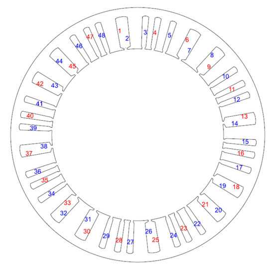
Figure 3.
Rotor unsymmetrical slots.
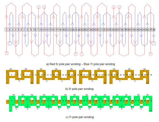
Figure 4.
Rotor windings schematic representation.
The optimization process of the rotor of the SESM begins with the choice of the displacement of the two windings in order to reduce the undesired mutual induced voltages. The decoupling produces an unsymmetrical rotor structure, where some slots are superposed and are, therefore, joined together (thus occasionally allocating both 10th and 14th harmonic winding in the same slot), as shown in Figure 3.
The schematic windings is reported in Figure 4a, by using different colors: the red line represents the winding which has the same pole pairs of 5r MMF space harmonic, while the blue line is the 7r pole pair winding. Both windings are also sketched in Figure 4b,c, respectively. These latter two sub-figures report also the number of turns that form each coil and the connection between two adjoining coils.
3.3. Mathematical Model and Space Harmonics Analysis
When the stator is fed at an angular frequency , the angular speed of the th MMF harmonic in the stator frame is:
Harmonic components propagate at different speeds and in different directions, thus the ± sign. Each MMF harmonic induces voltage at the fundamental frequency in the stator winding. The ordinal of the harmonic indicates how many wavelengths of a harmonic fit in a distance of one pole pair of the fundamental harmonic. This yields the pole pitch of the th harmonic:
A harmonic current linkage wave propagates in the air-gap at a fractional angular velocity . In machines with a complex MMF distribution, like those with fractional windings, running at synchronous speed means that the rotor travels at the same speed as one of those harmonics, and precisely the harmonic having the same number of pole pairs as the rotor . Therefore, the rotor travels faster than the harmonics with and is slower than the harmonics with . In the general case of asynchronously running motor with a generic mechanical speed the slip at different space MMF harmonics is defined as:
where is the stator angular frequency and is the rotor mechanical angular rotating frequency. The slip of the rotor with respect to the th stator harmonic is given by:
The angular frequency of the th harmonic on the rotor frame is thus:
The MMF space harmonics generated by the stator winding can be divided into three groups (with respect to a generic k, chosen among natural numbers):
- first group in which : in three phase windings, these harmonics tend to cancel each other;
- second group in which : harmonics rotating in the positive direction; and,
- third group in which : counter-rotating harmonics.
The spatial trend of the induced MMF by the stator winding is reported in Figure 5: the 10th (red wave) and the 14th (blue wave) harmonic sinusoidal waveform are represented for one half of machine.
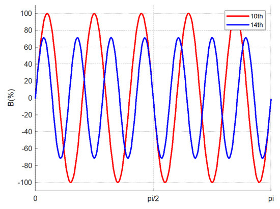
Figure 5.
Stator flux-density distribution due to the dominant harmonics.
The star of slots for the 10th and the 14th space MMF harmonics are in Figure 6 and Figure 7, respectively.
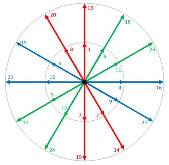
Figure 6.
Star of slot 10th magneto-motive force (MMF) harmonic.
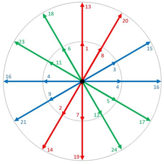
Figure 7.
Star of slot 14th MMF harmonic.
In correspondence with the star of slots, amplitude and winding factor of the MMF space harmonics have both been calculated and their values (in percentages) are reported in Table 2. Notice that the MMF harmonic amplitude has been calculated by imposing current flowing in one single conductor for each rotor slot.

Table 2.
Amplitude (%) and winding factor of MMF space harmonics.
The FFT analysis of the MMF is shown in Figure 8. As the winding is composed by an elementary section that repeats identically two times, the first significant MMF harmonic has four semiperiods in the airgap. However, the winding provides two significant dominant harmonics (i.e., the 10th and the 14th bars in Figure 8), which are exploited to provide the torque.
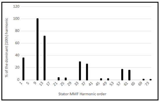
Figure 8.
FFT analysis of the air-gap flux density for a 24 FSCW.
However, there is still significant MMF harmonic content, which produces undesired harmonic induced voltages in the rotor windings, which must be filtered off, as will be shown in Section 5. One way to overcome this issue could also be using a stator winding, like the one in [25,26].
The expression of the th harmonic of the flux-density in the rotor reference is derived as in [24]. The flux density can be found introducing the vacuum permeability and the air gap length :
where:
- is the number of stator turns in series;
- is the number of stator phases;
- is the winding factor of the th harmonic; and,
- is the maximum value of the stator current.
and is the angular abscissa in the rotor reference.
In terms of the slip s, Equation (6) becomes:
for positive harmonics and:
for counter-rotating harmonics.
At the same supply frequency, the synchronous speed is different if the machine rotates in one direction or the other.
If the rotor is synchronous to the 14th harmonic, the 10th harmonic field induces an EMF in the corresponding rotor winding. The opposite happens when the rotor is synchronous with the 10th MMF harmonic.
The induced EMFs in each each of the rotor windings and are composed by many terms:
- the EMF induced by the stator MMF harmonic whose order is equal to the pole pairs of the rotor winding: ;
- the EMF induced by the stator MMF harmonics with ; and,
- the mutual flux linking the two rotor windings. .
In general, one has:
where the subscript indicates the number of pole pairs of the rotor winding, and the superscript indicates the MMF harmonic order .
The equivalent electric circuit of the two rotor windings can be analytically described by the following equation system:
where is the voltage at the rectifier terminals. In [24], a criterion for the cancellation of the mutual voltages is provided, based on the displacement of the two rotor windings:
The rotor circuits are represented by the following equations, representing the voltage balance at both sides of the DC/DC converter:
or
The induced voltages can be computed by integrating Equation (8):
with the same meaning of the subscripts and superscripts as Equation (9), and D bore diameter, number of turns of the rotor winding, and L ideal machine length.
The back EMFs produced by the hth MMF harmonic within one rotor winding with h pole pairs, if the harmonic rotates in the same direction as the rotor, are:
and:
if the harmonic rotates in the opposite direction.
The term in Equation (16) is:
3.4. Rotor Equivalent Circuit
Table 3 lists the main rotor equivalent circuit parameters and their measured values.

Table 3.
Rotor circuit specifications.
For the direct rotation, the rotor equivalent circuit is presented in Figure 9.

Figure 9.
Rotor winding connections at direct rotation: 10th harmonic power supply and 14th harmonic excitation field.
In the inverse rotation direction, the rotor equivalent circuit is in Figure 10. The circuit parameters are the same as in the previous case, but the harmonic power supply and, consequently, the harmonic excitation field is different in both cases.

Figure 10.
Rotor winding connections at inverse rotation: 14th harmonic power supply and 10th harmonic excitation field.
Four slip rings have been added and connected to the four terminals of the two rotor windings in order to measure the electrical quantities in the rotor, as will be shown in Section 5. The contacts between the slip rings and the metal graphite brushes have been taken into account in the rotor circuital model. They are represented by two variable resistors, named and . The non-linear behavior of the rotating brush contact has been assessed. The resulting voltage drop at their terminals is around 2 V.
The mutual inductance M takes into account the reciprocal interaction between the 10th and the 14th harmonic winding generated field and its value is quite low, due to the angular shift of the two rotor windings. Finally, a capacitor has been added to limit the voltage ripple.
3.5. Torque and Torque Density
The torque can be achieved by the Lorentz’ formula applied to the rotor windings:
where D is the bore diameter, L is the ideal length of the machine, and is the current linkage distribution of the rotor with with h pole pairs, as reported in [32].
Assuming:
where is the excitation current, is the load angle and is the number of the field winding turns and introducing Equation (7), at steady state and one has:
Finally,
The Torque-density is achieved by dividing the Torque for the volume:
where is the outer diameter of the machine, giving, for the maximum torque:
Introducing the stator and rotor electrical loadings as:
one has:
where is the diameter ratio. Therefore, the torque density using the tenth harmonic field winding is higher than that of the fourteenth. As it will be shown in the next section, the rotor electrical loading of the field winding is limited by the presence of two windings in the rotor. This limitation reduces the torque density at one half of that of a traditional synchronous machine.
4. Construction of SESM
The SESM generator has a three-phase 24-slots armature winding. The armature is allocated in the stator slots, and the structure has an external rotor. One rotor winding occupies 20 slots and the other one 28. The machine construction has been described in detail in [24], where the fractional slot concentrated winding technique is presented.
The design specifications of the motor are listed in Table 4, with the following meaning of symbols:

Table 4.
Design specifications.
- D is the bore diameter;
- L is stator core length;
- is the airgap length;
- is the rated current;
- is the phase voltage;
- f is the rated frequency; and,
- is the rated rotation speed.
The machine has a three-phase winding in the internal stator and an external rotor, suspended by bearings located in the front flange, as shown in Figure 11.

Figure 11.
Three dimensional sectioned rendering of the Self Excited Synchronous Machine (SESM).
The number of stator turns is achieved as:
where is the average flux-density, which, from Equation (6) can be taken as and the winding factor is taken from Table 2 as . With 14 turns per coil (28 turns per slot) a stator electric loading of AT/m is achieved.
From Section 3.5, when considering a low rotor electrical loading (due to the presence of two windings) of = 15,000 AT/m, , the torque density of a three-phase motor is Nm/l. The power density at 300 rpm is W/l, which is low in comparison to the typical values of the torque densities for an IPM motor. This limitation represents the main drawback of SESM. When considering that the volume of the motor is l, the torque is Nm the mechanical power of the machine is W, which is apparently low, although the low rated speed of rad/s must be considered.
Pictures of the front and the rear perspective of the SESM machine built are respectively shown in Figure 12.
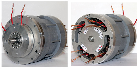
Figure 12.
Front and rear view of SESM.
An LCR Meter was used to measure the impedance of the stator and rotor windings; the frequency is 50 Hz and the obtained values are in Table 5.

Table 5.
Impedance windings measures.
5. Simulations and Measurements
On the basis of the the EMFs in Equation (9), the circuital model has been simulated. To validate simulations, an experimental test rig has been set up. In particular, the rotor windings have been modified in order to allow voltage measurement during rotation by means of slip-rings connected to the rotor terminals. The stator phase voltages and currents have been measured at no-load. Voltages and slip frequencies of the two rotor windings have been measured at synchronous speed. Table 6 shows the measurements at synchronous speed in direct rotation (torque produced by the 14th harmonic) i.e., 214.29 rpm (the fundamental frequency is always f = 50 Hz).

Table 6.
Synchronous speed at direct rotation measurements.
Table 7 shows the measurements at synchronous speed in inverse rotation (torque produced by the 10th harmonic) i.e., 300.00 rpm (also in this case the fundamental frequency is always f = 50 Hz).

Table 7.
Synchronous speed at inverse rotation measurements.
The PLECS® simulation software has been used to simulate the rotor electric circuits in order to verify the behavior of the machine in simulation and to have useful information on the design of the rectifier and the capacitor. Schematics have been drawn and the voltages and the currents in the 10 pole-pairs winding and in the 14 pole-pair winding have been plotted for both rotation directions.
The resistances of the metal-graphite brushes connected with the two rotor windings and the mutual inductance between these two windings have also been taken into account.
Figure 13a shows the schematic at inverse speed (i.e., 300 rpm) while Figure 13b shows the simulation results at inverse speed (i.e., 300 rpm).
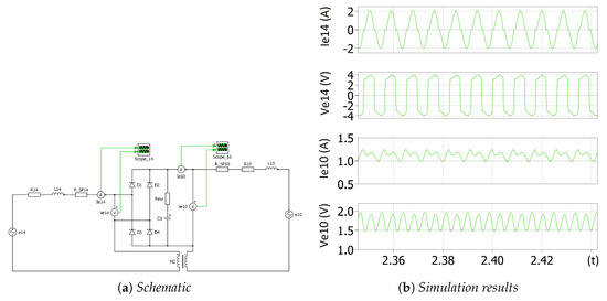
Figure 13.
10th harmonic MMF simulation.
The first diagram reports the current in the power supply winding (Ie14), while Ve14 represents the induced voltage in the same winding. The rectified current and voltage in the excitation winding are labeled Ie10 and Ve10, respectively.
The capacity value was chosen with the general aim of reducing the voltage ripple of the excitation winding, as mentioned in Section 3.3. Precise calculation of the capacitance concerns the optimal design of the system, which is not currently among the objectives of this design phase.
Figure 14 shows the scope measurements at inverse speed (i.e., 300 rpm), where:
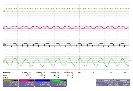
Figure 14.
10th harmonic voltage (V) and current (A) acquisition.
- C1 is the voltage in the 10th harmonic winding (V);
- C2 is the current in the 10th harmonic winding (I);
- C3 is the voltage in the 14th harmonic winding (V); and,
- C4 is the current in the 14th harmonic winding (I).
Figure 15a shows the schematic at direct speed (i.e., rpm), while Figure 15b shows the simulation results at direct speed (i.e., rpm).
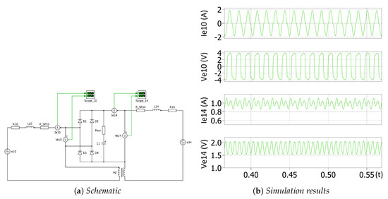
Figure 15.
14th harmonic MMF simulation.
As in the previous Figure 13a,b, the simulated voltages and currents of induced and excitating windings are reported; indeed, this time Ve10 and Ie10 are the induced voltage and current, while Ve14 and Ie14 are the rectified ones.
Due to the very low induced voltages, Schottky diodes have been used in order to reduce the voltage drop of the rectifier bridge.
Figure 16 shows the scope measurements at direct speed (i.e., rpm), where:
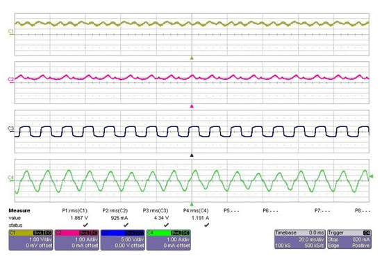
Figure 16.
14th harmonic harmonic voltage (V) and current (A) acquisition.
- C1 is the voltage in the 14th harmonic winding (V);
- C2 is the current in the 14th harmonic winding (I);
- C3 is the voltage in the 10th harmonic winding (V); and,
- C4 is the current in the 10th harmonic winding (I).
Rotor EMF Measurement and MMF Space Harmonic Synchronization
To execute this experimental test, both rotor windings have been connected to the system of brushes and slip-rings and disconnected from the rectifier, thus allowing the transduction of the voltages to the measurement apparatus. The rotor can synchronize either with the 10th MMF harmonic or with the 14th MMF harmonic, according to the sense of rotation. The synchronization speeds for the two space harmonics have been experimentally identified by measuring the back EMFs in the windings when the machine is rotated by an external motor. The minimum measured voltage indicates the winding is synchronous to the field.
The shown measurements are aimed at characterizing the machine and its performances. The measurements made so far confirm the assumptions made in the model.
In Figure 17a, the experimental results referring to the rotation in the direction of the 10th harmonic (synchronous speed rpm) are shown. Figure 17b shows the experimental results relevant to the rotation in the direction of the 14th harmonic. In this case, the synchronous speed is rpm. In Figure 17a,b, the synchronous speed is identified by the minimum of the induced voltage. The higher the voltage, the farther the speed from synchronism. The trends are quite in agreement with Equation (9), where and drop to zero at synchronous speed, while the other components remain.
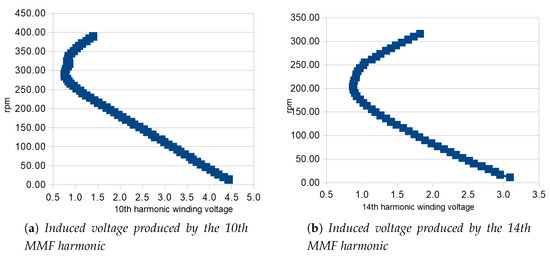
Figure 17.
EMF trends vs. rotation speed.
6. Conclusions
This paper analyzes a novel Self Excited Synchronous Machine (SESM), by comparing simulations and experiments. The excitation of the machine is supplied by rectifying the induced voltages caused in the rotor windings by the MMF space harmonic distribution. Furthermore, there’s no need of double supply, because of self-excitation, thus simplifying the feeding electrical system providing the necessary power for the machine usage.
The SESM avoids PM in-building, thus allowing for hard working conditions, such as in high temperature environments and in the case of emergency actuation; moreover, low maintenance is needed because of the simple electromechanical architecture.
PC simulations are compared to laboratory tests. The agreement between the tests and the model confirms the correctness of the model and of the design. The back EMFs show a minimum at synchronous speed. The simulation and experimental results are in agreement both in trend and in value.
The machine presents relatively low torque density compared with PM synchronous machines; moreover, its dimensions are still not comparable with the small sized synchronous generators. Finally, copper cost is increasing nowadays.
In order to optimize the whole system, a controlled rectifier for the induced voltages in the rotor windings, respectively related with MMF space harmonics, can improve the current/torque control of the proposed motor.
Author Contributions
Authors contributed equally to this work. Authors of this manuscript jointly conceived theoretical developments, revised the state of the art, provided suggestions for testing the method on windings with different slots/pole combinations. All authors have read and agreed to the published version of the manuscript.
Funding
This work was developed thanks to the grant of Regione Lazio “Progetti di Gruppi di Ricerca finanziati ai sensi della L.R. Lazio 13/08”.
Conflicts of Interest
The authors declare no conflict of interest.
Abbreviations
The following abbreviations are used in this manuscript:
| PM | Permanent Magnet |
| SESM | Self-Excited Synchronous Machines |
| MMF | Magneto-motive force |
| EMF | Electromagnetic Field |
References
- Meins, J.; Miller, L.; Mayer, W.J. The high speed Maglev transport system TRANSRAPID. IEEE Trans. Magn. 1988, 24, 808–811. [Google Scholar] [CrossRef]
- Dickhart, W.W. Status Of Transrapid Maglev. In Proceedings of the Electro International, New York, NY, USA, 16–18 April 1991; pp. 613–617. [Google Scholar]
- Bohn, G.; Steinmetz, G. The electromagnetic levitation and guidance technology of the ‘transrapid’ test facility Emsland. IEEE Trans. Magn. 1984, 20, 1666–1671. [Google Scholar] [CrossRef]
- Lu, G.; Chong, H.; He, W.; Zhang, J.; Pan, G. Harmonic analysis of the PWM inverter fed LSM drive system in the TRANSRAPID Shanghai. In Proceedings of the 2003 Sixth International Conference on Advances in Power System Control, Operation and Management ASDCOM 2003 (Conf. Publ. No. 497), Hong Kong, China, 11–14 November 2003; Volume 2, pp. 547–557. [Google Scholar]
- Dickhart, W.W. Transrapid MagLev Update. IEEE Aeros. Electron. Syst. Mag. 1987, 2, 5–8. [Google Scholar] [CrossRef]
- Luguang, Y. Progress of the Maglev Transportation in China. IEEE Trans. Appl. Supercond. 2006, 16, 1138–1141. [Google Scholar] [CrossRef]
- Nonaka, S.; Kawaguchi, T. A new variable-speed AC generator system using a brushless self-excited-type synchronous machine. IEEE Trans. Ind. Appl. 1992, 28, 490–496. [Google Scholar] [CrossRef]
- Nonaka, S.; Kawaguchi, T. Excitation scheme of brushless self-excited type three-phase synchronous machine. In Proceedings of the Conference Record of the 1991 IEEE Industry Applications Society Annual Meeting, Dearborn, MI, USA, 28 September–4 October 1991; Volume 1, pp. 443–448. [Google Scholar] [CrossRef]
- Nonaka, S.; Kesamaru, K. Analysis of new brushless self-excited single-phase synchronous generator by finite element method. In Proceedings of the Conference Record of the 1992 IEEE Industry Applications Society Annual Meeting, Houston, TX, USA, 4–9 October 1992; Volume 1, pp. 198–203. [Google Scholar] [CrossRef]
- Nonaka, S.; Kesamaru, K.; Horita, K. Analysis of brushless four-pole three-phase synchronous generator without exciter by the finite element method. IEEE Trans. Ind. Appl. 1994, 30, 615–620. [Google Scholar] [CrossRef]
- Inoue, K.; Yamashita, H.; Nakamae, E.; Fujikawa, T. A brushless self-exciting three-phase synchronous generator utilizing the 5th-space harmonic component of magneto motive force through armature currents. IEEE Trans. Energy Convers. 1992, 7, 517–524. [Google Scholar] [CrossRef]
- Shridhar, L.; Singh, B.; Jha, C.S. Transient performance of the self regulated short shunt self excited induction generator. IEEE Trans. Energy Convers. 1995, 10, 261–267. [Google Scholar] [CrossRef]
- Fukami, T.; Imamura, M.; Kaburaki, Y.; Miyamoto, T. A new self-regulated self-excited single-phase induction generator using a squirrel cage three-phase induction machine. In Proceedings of the 1995 International Conference on Energy Management and Power Delivery (EMPD ’95), Singapore, 21–23 November 1995; Volume 1, pp. 308–312. [Google Scholar] [CrossRef]
- Weber, J.; Rehfeldt, A.; Vip, S.; Ponick, B. Rotary transformer with electrical steel core for brushless excitation of synchronous machines. In Proceedings of the 2016 XXII International Conference on Electrical Machines (ICEM), Lausanne, Switzerland, 4–7 September 2016; pp. 884–889. [Google Scholar] [CrossRef]
- Stancu, C.; Ward, T.; Rahman, K.M.; Dawsey, R.; Savagian, P. Separately Excited Synchronous Motor With Rotary Transformer for Hybrid Vehicle Application. IEEE Trans. Ind. Appl. 2018, 54, 223–232. [Google Scholar] [CrossRef]
- Oliveira, M.O.; Bretas, A.S.; Garcìa, F.H.; Walantus, L.A.; Munoz, H.E.; Perrone, O.E.; Reversat, J.H. Design and analysis of brushless self-excited three-phase synchronous generator. In Proceedings of the International Conference on Renewable Energies and Power Quality, Santiago de Compostela, Spain, 28–30 March 2012. [Google Scholar] [CrossRef]
- Aoyama, M.; Noguchi, T. Rare-earth-less motor with field poles excited by space harmonics. In Proceedings of the 39th Annual Conference of the IEEE Industrial Electronics Society (IECON 2013), Vienna, Austria, 10–13 November 2013; pp. 7337–7342. [Google Scholar] [CrossRef]
- Izzat, L.F.A.; Heier, S. Development in design of brushless self-excited and self-regulated synchronous generator. In Proceedings of the 2013 International Conference on Renewable Energy Research and Applications (ICRERA), Madrid, Spain, 20–23 October 2013; pp. 1024–1029. [Google Scholar] [CrossRef]
- Dajaku, G.; Gerling, D. A novel tooth concentrated winding with low space harmonic contents. In Proceedings of the 2013 International Electric Machines Drives Conference, Chicago, IL, USA, 12–15 May 2013; pp. 755–760. [Google Scholar] [CrossRef]
- Dajaku, G.; Gerling, D. New self-excited synchronous machine with tooth concentrated winding. In Proceedings of the 3rd International Electric Drives Production Conference (EDPC-2013), Nuremberg, Germany, 29–30 October 2013. [Google Scholar]
- Aoyama, M.; Noguchi, T. Mathematical model of novel wound-field synchronous motor self-excited by space harmonics. In Proceedings of the 2014 International Power Electronics Conference (IPEC-Hiroshima 2014—ECCE ASIA), Hiroshima, Japan, 18–21 May 2014; pp. 1405–1411. [Google Scholar] [CrossRef]
- Aoyama, M.; Noguchi, T. Theoretical analysis of novel wound-field synchronous motor self-excited by space harmonics. In Proceedings of the 7th IET International Conference on Power Electronics, Machines and Drives (PEMD 2014), Manchester, UK, 8–10 April 2014; pp. 1–6. [Google Scholar] [CrossRef]
- Aoyama, M.; Noguchi, T. Estimation of rotor current based on mathematical model of wound-field synchronous motor self-excited by space harmonics. In Proceedings of the 2014 International Symposium on Power Electronics, Electrical Drives, Automation and Motion, Ischia, Italy, 18–20 June 2014; pp. 595–600. [Google Scholar] [CrossRef]
- Marignetti, F.; D’Aguanno, D.; Di Stefano, R.L. Design and optimization of self-excited synchronous machines with fractional slots. In Proceedings of the 2015 Tenth International Conference on Ecological Vehicles and Renewable Energies (EVER), Monte Carlo, Monaco, 31 March–2 April 2015; pp. 1–5. [Google Scholar] [CrossRef]
- Dajaku, G.; Gerling, D. Self-excited Synchronous Machine with High Torque Capability at Zero Speed. In Proceedings of the 2018 International Symposium on Power Electronics, Electrical Drives, Automation and Motion (SPEEDAM), Amalfi, Italy, 20–22 June 2018; pp. 1165–1171. [Google Scholar] [CrossRef]
- Jiang, J.; Dajaku, G.; Zhong, S.; Shi, Z.; Xie, W.; Gerling, D. Comparison between Conventional and Novel Self-excited Synchronous Motors. In Proceedings of the 2018 IEEE Student Conference on Electric Machines and Systems, Huzhou, China, 14–16 December 2018; pp. 1–6. [Google Scholar] [CrossRef]
- Elisabeta, S.; Ion, P.; Dorian, A.; Florina, P. The square root method for terminal voltage adjustment in a self-excited synchronous generator. In Proceedings of the 2017 5th International Symposium on Electrical and Electronics Engineering (ISEEE), Galati, Romania, 20–22 October 2017; pp. 1–4. [Google Scholar] [CrossRef]
- Abdelrazek, M.; Awad, H.; El-kholy, E.E. An experimental investigation of a self-excited synchronous generator: Loading characteristics and output voltage harmonics. In Proceedings of the 2017 Nineteenth International Middle East Power Systems Conference (MEPCON), Cairo, Egypt, 19–21 December 2017; pp. 823–829. [Google Scholar]
- Morikawa, M.; Heo, J.; Kondo, K.; Aoyama, M. Elucidation of the Cause of Positive and Negative Asymmetric Torque Generation of Self-Excited Wound-Field Synchronous Motor Utilizing Space Harmonics. In Proceedings of the 2018 International Symposium on Power Electronics, Electrical Drives, Automation and Motion (SPEEDAM), Amalfi, Italy, 20–22 June 2018; pp. 45–49. [Google Scholar]
- Santoso, H.; Wibawa, U.; Subroto, R.K.; Ardhenta, L. Impact of load and speed variation to frequency variation on single-phase self-excited induction generator. In Proceedings of the 2018 Electrical Power, Electronics, Communications, Controls and Informatics Seminar (EECCIS), Batu, East Java, Indonesia, 9–11 October 2018; pp. 5–8. [Google Scholar]
- Di Stefano, R.; Marignetti, F. Multicast Routing Protocol for LoRa Mesh Networks in Safety Critical Comunications. In ELECTRIMACS 2019; Springer: Cham, Switzerland, 2019; Volume 1, pp. 727–738. [Google Scholar]
- Pyrhönen, J.; Jokinen, T.; Hrabovcová, V. Design of rotating electrical machines windings of electrical machines. In Design of Rotating Electrical Machines; John Wiley and Sons, Ltd.: Hoboken, NJ, USA, 2008; Chapter 2; pp. 47–152. [Google Scholar] [CrossRef]
© 2020 by the authors. Licensee MDPI, Basel, Switzerland. This article is an open access article distributed under the terms and conditions of the Creative Commons Attribution (CC BY) license (http://creativecommons.org/licenses/by/4.0/).