Article

Distributed Resilient Voltage and Reactive Power Control for Islanded Microgrids under False Data Injection Attacks

School of Electrical and Electronic Engineering, North China Electric Power University, Beijing 102206, China
*
Author to whom correspondence should be addressed.
Energies 2020, 13(15), 3828; https://doi.org/10.3390/en13153828
Submission received: 16 June 2020 / Revised: 20 July 2020 / Accepted: 23 July 2020 / Published: 25 July 2020
(This article belongs to the Special Issue Smart Grids and Flexible Energy Systems)

Abstract

:
This paper addresses the problem of voltage and reactive power control of inverter-based distributed generations (DGs) in an islanded microgrid subject to False Data Injection (FDI) attacks. To implement average voltage restoration and reactive power sharing, a two-layer distributed secondary control framework employing a multiagent system (MAS)-based dynamic consensus protocol is proposed. While communication network facilitates distributed control scheme, it leads to vulnerability of microgrids to malicious cyber-attacks. The adverse effects of FDI attack on the secondary controller are analyzed, and the necessary and sufficient conditions to model stealthy attack and probing attack are discussed in detail. A trust-based resilient control strategy is developed to resist the impacts of FDI attack. Based on the forward-backward consistency criterion, the self-monitoring and neighbor-monitoring mechanisms are developed to detect the misbehaving DGs. A group decision-making mechanism is also introduced to settle conflicts arising from the dishonest trust index caused by colluding attacks. A novel mitigation countermeasure is designed to eliminate the adversarial effects of attack: the discarding information mechanism is used to prevent the propagation of false data in the cooperative network while the recovery actions are designed to correct the deviations of collective estimation error in both transient disturbance and continuous FDI attack scenarios. Through a theoretical analysis, it is proved that the proposed mitigation and recovery mechanism can maintain the correct average estimates of voltage and reactive power, which ensures the secondary control objectives of microgrids under FDI attack. Simulation results on an islanded microgrid show the effectiveness and resilience of the proposed control scheme.

1. Introduction

Due to the rapid advances and wide applications of measurements, communication and computation technology, the traditional power grid has been experiencing a revolution towards a smart grid, which can enhance reliability, safety and efficiency of power system [1]. In order to overcome the intermittent characteristics of distributed generations (DGs), as well as fully exploit the benefit of DGs, microgrids are gradually playing an important role in the smart grids [2]. A microgrid is able to operate in grid-connected or islanded mode, and transfer between these two modes seamlessly. In an islanded microgrid, the traditional droop-based primary control introduces voltage and frequency deviations from their nominal values. Due to the mismatch of line impedance, primary control is unable to achieve reactive power sharing among DGs, which impairs the dynamic performance and power supply quality of microgrids [3,4].
Various hierarchical control frameworks consisting of primary, secondary and tertiary control levels have been proposed to improve the performance of microgrids [5]. To stabilize the voltage and frequency of microgrids, the primary control is designed mainly based on the droop technique, which relies on only local information of each DG unit [6]. The secondary control is necessary to compensate for the steady-state error of the voltage and frequency caused by primary droop control and to restore the voltage and frequency to their nominal values. The tertiary control is aimed at optimizing the operating cost and energy management of microgrids. In general, centralized control and distributed control are two common strategies in secondary control level [7]. In traditional centralized strategy, a central control unit and a complicated fully-connected communication network are required to collect information from all DGs. Under such circumstance, any single point of failure may cause instability of the entire system, which impairs the reliability of microgrids. The multiagent system (MAS) -based distributed control strategy has been proposed as a promising solution to electric grids with increasing penetration of DGs [8,9,10]. In contrast to the centralized scheme, the MAS-based distributed control scheme has the following advantages: (1) Centralized scheme requires a high bandwidth network to collect system-wide information, while MAS-based scheme only relies on local information exchange among neighboring DGs. As a result, the sparse communication network can be used for MAS-based distributed scheme, which significantly reduces the communication cost. (2) Without any reliance on a centralized control unit, the MAS-based distributed scheme is more suitable to handle topology variations and plug-and-play operations, which enhances the scalability and flexibility of microgrids. (3) MAS-based distributed control scheme ensures more robust performance under imperfect communication situations, such as time delay and noise [11]. Thus, the reliability of system can be improved compared to the centralized scheme.
Despite their remarkable advantages, distributed control schemes are more vulnerable to malicious cyber-attacks since they lack the capacity of global situation awareness. Cyber-attacks are considered as serious threats to the security of networked control systems and have received great concern in both industrial and academic fields. Roughly, cyber-attacks can be categorized into: Denial-of-Service (DoS) attacks and False Data Injection (FDI) attacks. The DoS attack aims to make information unavailable by blocking legitimate data transmissions, while the FDI attack aims to modify the integrity of transmitted data packets [12]. To design a resilient control strategy, it is of significance to identify the adverse effects of FDI attack on the system performance from the attackers’ perspective [13]. If the attackers have obtained the prior knowledge about the communication topology and control protocol of the microgrid system, such intelligent attackers can inject coordinated attack signals in multiple nodes without exposing themselves to any intrusion detection system [14,15]. With regards to distributed control theory, asymptotic convergence of agents can still be achieved under such type of attack, even though the final operating state may be incorrect. In this case, the control objectives of microgrids will be maneuvered artificially by the attackers. Thus, the study of the impacts of FDI attack on distributed microgrids controller is of both theoretical merit and practical value.
Much research work has been conducted in cyber-attacks on the power grid with centralized control structure [16]. Security and resilience is an area of growing concern for the smart power grid applications, such as power system state estimation, electricity market and Phasor Measurement Unit (PMU) data [17]. Conventional resilient control strategies such as observer-based state reconstruction [18], state prediction-aided method [19] and machine learning-based attack detection mechanism [20] have been proposed to mitigate the vulnerability caused by malicious cyber-attacks. However, these strategies assume a control center to collect system-wide information, which is not suitable for the distributed control structure of microgrids. Although the machine learning-based intrusion detection mechanism is model independent, it requires a huge historical data set for training the algorithms. The lack of the corresponding data set containing multiple attack scenarios hinder the further application on this method in microgrids.
With regard to distributed secondary control scheme of microgrids under cyber-attacks, only few efforts have been reported in the aspect of intrusion detection mechanisms and mitigation measures. A transient model -based technique was proposed to detect FDI attacks on the centralized controller of microgrids in [21]. In [22], a stable region concept was proposed, in which the impacts of FDI attack on the utilization level of microgrids were discussed, but no mitigation countermeasures were presented. In [23], a FDI attack was detected by the variation of the candidate invariants. However, this approach requires accurate model checking tools, which increases the computational burden and complications. A signal temporal logic (STL)-based attack detection mechanism was proposed in [24]. The upper and lower bounds of the voltage and current were estimated, and the state information falling out of the bounds implies the presence of attack. However, it should be noted that false states, even within the given bounds, could cause large deviations in the final operation point. In [25], a leader-follower consensus algorithm was used to restore the frequency of an islanded microgrid. The proposed distributed observer strategy can only reconstruct the constant attack signals, and the assumption of an attack-free leader should be guaranteed. The extended state observer (ESO) method was presented in [26] to estimate the disturbance signals including FDI attack on microgrids. However, the derivative of disturbance signals should be zero in the steady state, and the situation that ESO itself may be attacked by adversaries is not considered. The trust-based resilient control approaches were introduced to the distributed energy management [27], cognitive radio sensor network [28], and unmanned aerial vehicles system [29] to minimize the adverse effects of malicious attacks. However, these approaches fail to consider the colluding attacks, which can manipulate the trust value of agents and lead to the failure of the proposed defense mechanism. To the author’s knowledge, little research has been conducted to take into account the effects of FDI attack on voltage and reactive power coordination of an islanded microgrid, and the resilient secondary control scheme design has not been discussed, which motivates the current study.
In this paper, we focus on the attack detection and mitigation techniques to improve the resilience of distributed voltage and reactive power control of islanded microgrids with respect to FDI attack. Unlike the grid-connected microgrids in which voltage and frequency are supported by the main grid, the control scheme to coordinate multiple DGs directly affects the voltage and frequency stability, power sharing and dynamic performance of islanded microgrids. Furthermore, the low rating of DGs, lack of static compensation devices, and line impedance mismatch requires an accurate reactive power sharing to avoid overloading to cause damage of DGs [9,10]. A two-layer distributed control scheme is presented to implement average voltage restoration and reactive power sharing, in which a MAS-based dynamic consensus protocol is employed to estimate the average voltage and reactive power, and a PI controller is designed to compensate for the deviations caused by the primary control. A trust-based control scheme is proposed to resist the impacts of FDI attack on the microgrid control system. The main contribution of this paper is summarized as follows: (1) The adverse effects of FDI attack on the proposed voltage and reactive power control scheme are analyzed in detail. The necessary and sufficient conditions for attackers to conduct stealthy attack and probing attack are discussed according to the cumulative effect of the injected false data. (2) A trust-based resilient control strategy is proposed, in which the trust evaluation result manipulated by the colluding attack is considered. A forward-backward consistency criterion is designed to detect the misbehaving DGs, and a group decision-making mechanism is introduced to settle conflicts arising from the dishonest trust index caused by colluding attack. (3) A novel mitigation countermeasure is proposed to eliminate the impacts of FDI attack. An information discarding mechanism is designed to prevent the propagation of false data in the cooperative network. Through a theoretical analysis, we show that the proposed recovery actions can correct the deviations of the collective estimation error caused by the attack, in both transient disturbance and continuous FDI attack scenarios. Consequently, the correct average estimates of voltage and reactive power can be maintained and the secondary control objectives are not affected by FDI attack.
The rest of this paper is organized as follows: Section 2 depicts the cyber physical architecture of the islanded microgrid along with the distributed secondary control to achieve average voltage restoration and reactive power sharing. Section 3 presents the adverse effects of FDI attack on the proposed distributed control scheme, and the conditions for attackers to conduct stealthy attack and probing attack are given in detail. Section 4 provides the trust-based resilient control framework to detect attack and eliminate the impacts of false data on the secondary control objectives. Simulation results and discussion are presented in Section 5. Finally, the conclusions are drawn in Section 6.

2. Secondary Voltage and Reactive Power Control for Islanded Microgrids

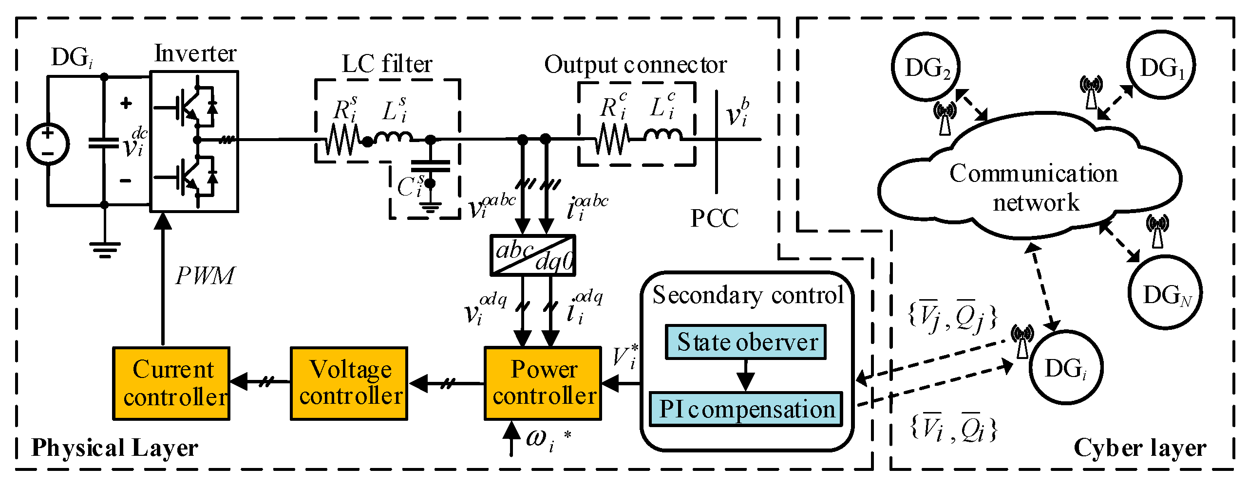
2.1. Cyber-Physical Model of Islanded Microgrids

Figure 1 presents the cyber-physical model of an islanded AC microgrid containing several DGs. In the physical layer of the microgrid, three-phase inverter-based DG i (i = 1,…,N) is connected to the microgrid through a DC/AC inverter, an LC filter and a output connector. L i s , R i s and C i s represent the inductance, resistance and capacitance of the LC filter, while L i c and R i c represent the inductance and resistance of the output connector.
As shown in Figure 1, the primary control of DG i includes the droop-based power controller, PI voltage controller and PI current controller. For DG i , the droop technique used in power controller mimics the droop mechanism of the traditional synchronous generator to regulate angular frequency ω i and voltage V i according to active and reactive power respectively, and can be given by [8,10]:
{ V i = V i n i Q Q i ω i = ω i m i p P i
where m i p and n i Q are the frequency and voltage droop coefficients. P i and Q i are the fundamental components of active and reactive power, which can be obtained via two low-pass filters. ω i and V i are the reference signals for primary control, and V i is derived by the secondary control in this paper.
In the cyber layer, each DG is considered as an agent which shares information with its neighbors through a sparse communication network. The communication network is described as an undirected graph G = ( V , Ξ ) , where V = { 1 ,   , N } denotes the set of nodes corresponding to DGs, and Ξ V × V is the set of edges corresponding to the communication links. Node j is a neighbor of node i if there exists an edge defined as ( i ,   j ) Ξ . W = [ w i j ] R N × N is defined as the adjacency matrix, where w i i = 0 for all i, and w i j = 1 if ( i ,   j ) Ξ , otherwise, w i j = 0 . N i = { j | ( i ,   j ) Ξ } represents the set of neighbors of node i, and the degree of node i is defined as d i = j ϵ N i w i j . The Laplacian matrix L of the graph G is expressed as L = D W , where D = diag { d 1 , d 2 , , d N } is the degree matrix of the graph. A path is defined as a connected edge in a graph, and the graph G is connected if there is a path between any two nodes.

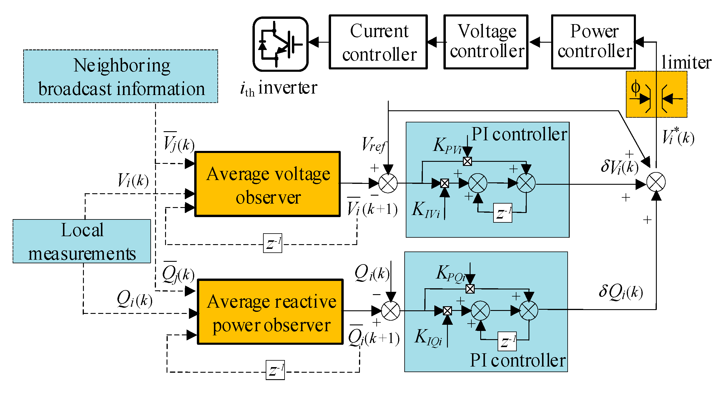
2.2. Distributed Secondary Control Framework for Voltage and Reactive Power

The droop characteristic of primary control makes the voltages of DGs deviate from the rated value. Meanwhile, accurate reactive power sharing among DGs cannot be achieved due to the line impedance mismatch. The objective of the secondary control in this paper is to restore the average voltage to the rated value while maintaining reactive power sharing of among DGs. Figure 2 shows the proposed framework for voltage and reactive power control, which involves estimation sublayer and compensation sublayer. The estimation sublayer is responsible to obtain the average information of voltage and reactive power in a distributed manner, then sends it to the compensation sublayer. The compensation sublayer calculates the reference signal V i and sends it to the primary control to regulate average voltage and achieve reactive power sharing among DGs.
(1) Estimation sublayer: For global average voltage restoration and reactive power sharing, a state observer based on discrete dynamic consensus algorithm [30] is proposed to acquire the average information of voltage and reactive power. At each iteration k , x ¯ i ( k ) = { V ¯ i ( k ) ,     Q ¯ i ( k ) } (i = 1,…,N) denotes the average estimates of voltage and reactive power. DG i receives the neighboring estimates x ¯ j ( k ) = { V ¯ j ( k ) ,     Q ¯ j ( k ) } j N i via the communication network, and the state observer is updated as:
{ | V ¯ i ( k + 1 ) = V ¯ i ( k ) + ε j N i w i j ( V ¯ j ( k ) V ¯ i ( k ) ) u i , V ( k ) + V i ( k + 1 ) V i ( k ) | Q ¯ i ( k + 1 ) = Q ¯ i ( k ) + ε j N i w i j ( Q ¯ j ( k ) Q ¯ i ( k ) ) u i , Q ( k ) + Q i ( k + 1 ) Q i ( k )
where x i ( k ) = { V i ( k ) ,     Q i ( k ) } denotes the measured voltage and reactive power of DG i . ε is the step-size which should satisfy 0 < ε < ( 1 / m a x i = 1 , , N d i ) to ensure the convergence of algorithm. u i ( k ) = { u i , V ( k ) ,     u i , Q ( k ) } denotes the cooperative control input.
By referring to Theorem 3.1 in [30], summing x ¯ i ( k ) in Equation (2) over all agents, then the following equation can be obtained:
i V x ¯ i ( k + 1 ) = i V x ¯ i ( k ) + ε i V j N i w i j ( x ¯ j ( k ) x ¯ i ( k ) ) + i V ( x i ( k + 1 ) x i ( k ) )
In Equation (3), the summation i V j N i ( x ¯ j ( k ) x ¯ i ( k ) ) always equals to zero, because the communication topology is an undirected graph and for all i and j we have w i j = w j i , every term in the summation has its opposite counterpart. The initialization condition of Equation (2) is set as x ¯ i ( 0 ) = x i ( 0 ) , then i V x ¯ i ( k ) = i V x i ( k ) always holds true during the iteration process. Under the effects of the cooperative control input, we have lim k x ¯ i ( k ) = lim k x i ( k ) . Therefore,   x ¯ i ( k ) converges to the average value of voltage and reactive power, which can be expressed as:
{ | lim k V ¯ i ( k ) = 1 N lim k i V V i ( k ) | lim k Q ¯ i ( k ) = 1 N lim k i V Q i ( k )
Remark 1.
The traditional control for the voltage restoration and reactive power sharing of an islanded microgrid employs a centralized structure [31], in which the measurement information of overall DGs is required to calculate the average value. Different from the traditional centralized way, the state observer with dynamic consensus algorithm enables DGs to estimate the average voltage and reactive power in a fully distributed manner. Furthermore, considering the discrete nature of communication data transmission in the secondary control level of the microgrid, the discrete time-based method is more suitable for the engineering practice.
(2) Compensation sublayer: To achieve average voltage regulation, each DG requires to measure the voltage error and compensates for the deviation caused by the primary control. Meanwhile, the average reactive power estimate serves as the reference value for each DG to realize reactive power sharing. Two compensation terms for DG i are calculated using [31]:
{ | δ V i ( k ) = K P V i A V E ( V r e f V ¯ i ( k ) ) + K I V i A V E p = 0 k ( V r e f V ¯ i ( p ) ) | δ Q i ( k ) = K P Q i A V E ( Q ¯ i ( k ) Q i ( k ) ) + K I Q i A V E p = 0 k ( Q ¯ i ( p ) Q i ( p ) )
where K P V i A V E and K I V i A V E are the proportional and integral gains of PI controller for average voltage restoration, and K P Q i A V E and K I Q i A V E are the proportional and integral gains of PI controller for reactive power sharing. V r e f denotes the global reference voltage for all DGs. The compensation terms obtained in (5) are finally added to V r e f , and the reference signal V i sent to the primary control of DG i can be calculated as:
V i ( k ) = V r e f + δ V i ( k ) + δ Q i ( k )
The secondary controller typically includes the voltage limiter (see Figure 2). This limiter is responsible to carry out two tasks: it limits the voltage variations at terminal of each DG and limits the transmission line loading. According to Figure 2, the output voltage of each DG is limited to V r e f ϕ V i V r e f + ϕ to prevent voltage from exceeding the boundary.
With adoption of the cooperative dynamic consensus algorithm and the PI controllers for a connected communication topology for a microgrid, the solutions in Equation (2) shall converge to:
lim k V ¯ i ( k ) = V r e f ,   lim k Q ¯ i ( k ) = 1 N lim k i V Q i ( k ) ,   i V
The above equation indicates that the control objectives of average voltage restoration and reactive power sharing can be achieved by the proposed control framework. However, for injecting false data into a single or multiple agents, abnormal discontinuity will be introduced in updating Equation (2), which disrupts the consensus between agents and ultimately affects the final convergence results in Equation (7). The modeling of such attack and its impacts on the proposed secondary voltage and reactive power control scheme is discussed in the following section.

3. Vulnerability Analysis of the Distributed Control Scheme Subject to FDI Attack

Considering that the attackers penetrate into the control system of the microgrid and inject false data into the proposed distributed cooperative controller, the adverse effects of FDI attack on the convergence is discussed in detail in this section.
In the MAS-based cooperative control framework, each DG is considered as an agent. When the attacker conduct FDI attack to some agents, these agents will become misbehaving agents [15,25,27]. The misbehaving agents will be manipulated to inject false data into the state variables V ¯ i ( k ) and Q ¯ i ( k ) in Equation (2), where DG i is an misbehaving agent and k denotes the step of the iterative process. Thus, we propose a general form of the algorithm (2) under FDI attack which can be modeled as:
{ | V ¯ i ( k + 1 ) = V ¯ i ( k ) + u i , V ( k ) + V i ( k + 1 ) V i ( k ) + f i , V a ( k ) | Q ¯ i ( k + 1 ) = Q ¯ i ( k ) + u i , Q ( k ) + Q i ( k + 1 ) Q i ( k ) + f i , Q a ( k )
where DG i is the misbehaving DG, f i , V a ( k ) and f i , Q a ( k ) represent the false data injected into V ¯ i ( k ) and Q ¯ i ( k ) , respectively.
It can be observed from Equation (8) that the attacker can easily ruin the convergence of the proposed cooperative controller (2). However, if the attacker breaks the convergence, the system operator or the agents can easily know the presence of attack. From the attackers’ perspective, the attack activities should keep stealthy to make them less detectable by the intrusion detection mechanism of the microgrid system. To design a resilient control scheme, it is crucial to understand the adverse effects of such undetectable attacks.
Define x ¯ ( k ) = [ x ¯ 1 ( k ) , x ¯ 2 ( k ) , , x ¯ N ( k ) ] T as the vector of voltage and reactive power estimates, f V a ( k ) = [ f 1 , V a ( k ) , f 2 , V a ( k ) , , f N , V a ( k ) ] T and f Q a ( k ) = [ f 1 , Q a ( k ) , f 2 , Q a ( k ) , , f N , Q a ( k ) ] T represent the vectors of false data injected to the cooperative controllers. The solution of Equation (8) under the attack can be expressed as [32]:
x ¯ ( k ) = A c k x ¯ ( 0 ) + p = 0 k 1 A c k p 1 ( x i ( p + 1 ) x i ( p ) ) + p = 0 k 1 A c k p 1 f a ( p )
where A c = I ε L is the closed-loop matrix. f a ( k ) = { f V a ( k ) , f Q a ( k ) } denotes the overall attack signals at k iteration. By referring to [30], the global dynamic of Equation (9) in steady state can be given by:
x ¯ ( k ) 1 N N i = 1 N x i ( k ) + p = 0 k 1 A c k p 1 f a ( p )
where 1 N = [ 1 , 1 , , 1 ] T . In Equation (10), the first term on the right-hide side represents the desired consensus value (i.e., the average value of voltage and reactive power), and the second term reflects the cumulative effect of the attack signals on the cooperative controller. It can be seen that the attacker can disrupt the convergence of the algorithm by injecting false data to the control system. However, in order to keep the attacks undetectable to the system operator or the intrusion detection mechanism, smart attackers can adjust the cumulative effect of attack signals to manipulate the final operating state of microgrids while maintaining the convergence of Equation (10).
Definition 1.
Stealthy attack. The cumulative effect of attack signals on cooperative control is limited for the iteration process. If there exists a constant H such that:
k = 0 | f i , V a ( k ) | H ,   k = 0 | f i , Q a ( k ) | H ,   i V
Then, the attack makes Equation (10) converges to an incorrect stable point, that
lim k V ¯ i ( k ) = V r e f a ,   lim k Q ¯ i ( k ) = Q a ,   i V
where V r e f a V r e f and Q a 1 N i V Q i ( k ) .
According to Equation (10), A c has a simple eigenvalue 1 and all other eigenvalues lie in the open unit disk. By referring to [32], lim k p = 0 A c k p 1 f a ( p ) will converge to a nonzero constant, i.e., lim k p = 0 A c k p 1 f a ( p ) = c , where c is a constant. Thus, it can be obtained that the final value of Equation (10) will converge to lim k x ¯ i ( k ) = 1 N lim k i V x i ( k ) + c . In this case, we can observe that V ¯ i ( k ) and Q ¯ i ( k ) converge to a stable but incorrect final point, which will affect the control objectives of the proposed secondary control scheme.
Remark 2.
The condition Equation (11) shows that, the attacker without any prior knowledge of system can still manipulate the final operating state of microgrids while maintaining the convergence of the cooperative control. When the convergence is achieved, each agent will think that the average estimates of voltage and reactive power are acquired, thus such kind of attack is stealthy.
Definition 2.
Probing attack. The cumulative effect of attack signals on cooperative control is zero for the iteration process. If the attack signals satisfy condition Equation (11) and the following equation holds,
lim k k = 0 i V f i , V a ( k ) = 0 ,   lim k k = 0 i V f i , Q a ( k ) = 0 ,   i V
the control objectives in Equation (7) can still be achieved in steady state even under probing attack.
By summing x ¯ ( k + 1 ) in Equation (8) over all DGs, the following equation holds:
i V x ¯ i ( k + 1 ) = i V x ¯ i ( k ) + i V ( x i ( k + 1 ) x i ( k ) ) + i V f i a ( k ) = i V x ¯ i ( 0 ) + i V ( x i ( k + 1 ) x i ( 0 ) ) + p = 0 k i V f i a ( p )
Since the initialization condition is set as x ¯ i ( 0 ) = x i ( 0 ) , if the condition p = 0 k i V f i a ( p ) = 0 is satisfied, i V x ¯ i ( k + 1 ) = i V x i ( k + 1 ) will hold. Thus, the correct average estimates of voltage and reactive power can still be acquired and the steady state of the microgrid will not be affected.
Remark 3.
The condition Equation (13) indicates that the attacker can intrude the control system of the microgrid without causing any adverse effects on the objectives of the secondary control. By injecting zero-sum attack signals into a single agent or symmetric attack signals into multiple agents, probing attack can help the attacker to confirm the success of intrusion and prepare for more serious attacks in the long run process.
Definition 3.
Destabilization attack. If the attack signals cannot satisfy the conditions Equations (11) and (13), the final convergence of the agents will be ruined, leading to the failure of the cooperative control.
Remark 4.
According to Equation (10), l i j m = [ I ε L ] i j m with [   ] i j denotes the element ( i , j ) of a matrix, and m represents the length of the shortest path from agent j to agent i. It can be easily seen that an attack on a compromised agent can affect the intact agents that are reachable from it. That is, an attack on a single agent can propagate in the cooperative network, which even destabilizes the entire system. However, from the attackers’ perspective, the duration of FDI attack should be as short as possible to make them less detectable. Thus, the FDI attack should not span the entire time to avoid the attacker exposed to the detection mechanism.
To show the adverse effects of the abovementioned attack strategies on the proposed cooperative controller (2), a case study is presented in Figure 3. The microgrid test system consists of five DGs and three loads. The detailed control parameters and communication topology are presented in Section 5. As illustrated in Figure 3, the microgrid works in islanded mode from t = 0 s, and the proposed secondary controller is applied at t = 0.5 s. Then the average voltage of DGs can gradually restore to the rated value 380 V while maintaining the accurate reactive power sharing. From 1.5 s to 2 s, the probing attack signals 0.3 V and −0.3 V are injected into DG 1 and DG 4 according to Equation (8), such that the cumulative effect of FDI attack meets the condition Equation (13). After the attack is removed at t = 2 s, it can be seen that V ¯ ( k ) and Q ¯ ( k ) gradually converge to their respective normal values as stated in Equation (7). The control objectives can still be achieved under such type of attack. From 3 s to 3.3 s, a stealthy attack signal f 4 , Q a ( k ) = 300 10 × ( k 300 ) kVar is injected into the average reactive power controller of DG 2 . We observe that the convergence of the control scheme are not ruined, but the final stable points of V ¯ ( k ) and Q ¯ ( k ) are affected by the attack, which leads to abnormal increase of voltage and reactive power of each DG. At t = 4.5 s, the destabilization attack is initiated with a sinusoidal attack signal injected into the average reactive power controller of DG 5 . One can observe that the compromised DG 5 can affect the other intact DGs and the false data propagates in the cooperative network which causes instability of the entire system.

4. Trust-Based Resilient Control Framework for Microgrids against FDI Attack

To defend against FDI attack on the cooperative control for voltage and reactive power of microgrids, a resilient control framework is developed in this section. The trust-based resilient control strategy relies on the local information to detect the misbehaving DGs, determines the malicious DGs according to the common trust value obtained by the group decision-making mechanism, and eliminates the impacts of attack on the cooperative network through the recovery actions.

4.1. Misbehaving DG Detection Phase

(1) Detection criteria: The misbehavior of DG i is defined as the abnormal update in cooperative control law (2) in the presence of FDI attack. The proposed detection method is based on the forward-backward consistency in updating Equation (2). Specifically, at iteration k,   DG i relies on its own information x ¯ i ( k ) and its neighbors’ information x ¯ j ( k ) to obtain the forward update value x ¯ i ( k + 1 ) . Then, the following backward update rule is used to obtain the estimate of x ¯ i ( k ) :
x ^ i ( k ) = 1 1 ε j N i w i j ( x ¯ i ( k + 1 ) ε j N i w i j x ¯ j ( k ) x i ( k + 1 ) + x i ( k )
where x ^ i ( k ) = { V ^ i ( k ) , Q ^ i ( k ) } is the estimated value of x ¯ i ( k ) . The backward update rule is derived from (2), and if there is no attack on DG i , we should have x ^ i ( k ) = x ¯ i ( k ) . Let θ i j ( k ) denotes the detection result of DG j to DG i at iteration k, and can be expressed as:
{ | θ i j ( k ) = 1 ,     i f   { V ^ i ( k ) , Q ^ i ( k ) } = { V ¯ i ( k ) , Q ¯ i ( k ) } | θ i j ( k ) = 0 ,                   o t h e r w i s e
where j N i + , and N i + = { i     N i } is the extended set of neighbors of DG i .
(2) Detection process: According to Equation (16), the detection of attack on DG i can be divided into the self-monitoring mechanism implemented by DG i itself, and the neighbor-monitoring mechanism implemented by the neighbors of DG i .
Self-monitoring mechanism: At iteration k, DG i calculates x ¯ i ( k + 1 ) according to the forward update rule (2). At iteration k+1, the estimated value x ^ i ( k ) is obtained by the backward update rule Equation (15). By comparing whether x ^ i ( k ) and x ¯ i ( k ) are equal, DG i is able to detect whether it is suffering from a FDI attack.
Neighbor-monitoring mechanism: Considering two neighboring DGs i and j, DG j is responsible to monitor the misbehavior of DG i . For DG j to perform the estimation in (15), two-hop information is required, including the 1st-hop information set { x ¯ i ( k + 1 ) ,   x ¯ i ( k ) ,   x i ( k + 1 ) , x i ( k ) } from DG i and the 2nd-hop information set { x ¯ s ( k ) ,   s N i } from DG i ’s neighbors. Then, DG j compares the estimated value x ^ i ( k ) with the actual value x ¯ i ( k ) to determine whether DG i is experiencing an attack.
Remark 5.
In [33,34], only 1st-hop information is used to estimate the upper and lower bounds of state variables of DGs, and the state exceeding the bounds indicates the presence of attack. However, according to the analysis in Section 3, the false state even within the given bounds could affect the final operating point of microgrids. Although the additional 2nd-hop information increases a small amount of communication burden, it greatly improves the accuracy of intrusion detection. Moreover, by introducing the self-monitoring mechanism, the agent can realize self-diagnosis of its misbehavior, which also provides redundant information for the trust evaluation process.

4.2. Trust Evaluation Phase

In multiagent network, trust index is defined as a confidence value that one agent puts on another agent [35]. Each DG maintains a trust index about its neighbors. T i j ( k ) represents DG j ’s attitude about DG i up to iteration k, where j N i + . In particular, T i i ( k ) denotes the trust level of DG i to itself. T i j ( k ) [ 0 , 1 ] , 1 indicates the full trust level while 0 indicates the full distrust level. At each iteration, the trust index T i j ( k ) is updated as:
T i j ( k + 1 ) = α θ i j ( k ) + ( 1 α ) T i j ( k )
where α > 0 is the sensitivity factor, which determines the change rate of T i j ( k ) . It also guarantees that if the attack is not persistent after a while, the trust value will be recovered depending on the current observations. Initially, T i j ( 0 ) is set as 1 indicating that DG j has full trust in DG i . According to the detection result (16), if θ i j ( k ) = 1, then T i j ( k + 1 ) = 1 indicates that DG i is in the absence of attack; if θ i j ( k ) = 0, then T i j ( k + 1 ) starts to decrease which indicates that DG i is suffering from attack.
In the traditional trust-based resilient system, if T i j ( k ) falls below a certain threshold T L , then DG i will be identified as malicious by its neighbors. However, this strategy is vulnerable to the colluding attack. The trust index can be manipulated by a colluder to keep the malicious DGs stay in the network or isolate the normal DGs from the network, which could cause instability of the microgrid in unforeseeable ways.

4.3. Malicious DGs Indentification Phase

While the abovementioned detection and trust evaluation process is effective for identifying the malicious DG under non-colluding attacks, it fails to consider the impacts of colluding attacks on the trust model. In general, colluding attacks may occur when two or more neighboring DGs are compromised. Figure 4 shows the colluding attack on the trust evaluation process. As illustrated in Figure 4, DG j monitors DG i ’s behavior and updates the trust index T i j according to the information from DG i . Considering that DG j suffers from colluding attack, the attacker could tamper the trust index and distort DG j ’s attitude about DG i . The colluding DG j can deliberately raise the trust index when the malicious behavior of DG i has been detected. Thus, the false information will continue to propagate in the cooperative network. Another collusion is that DG j intentionally reduce the trust index of an intact neighbor DG i . Under such circumstances, the normal DG will be isolated from the network, which might result in overloads to cause disable or damage to other DGs.
To defend against a colluding attack, a group decision-making mechanism is introduced to settle conflicts arising from the dishonest trust index. The general idea is that for DG j monitoring DG i ’s misbehavior, other than only relying on its own local trust index to identify the malicious attack, DG j receives the trust values from other neighbors of DG i and utilizes them to form a collaborative opinion. To determine whether the targeted DG is malicious or not, at least half of its neighbors should share the same trust index. The similar group decision-making process have been used in other distributed systems, such as vehicular ad hoc networks [36] and wireless sensor networks [37]. The group decision-making process to identify the targeted DG as malicious or normal is presented as follows:
Step 1: At iteration k, DG i sends its own trust index T i i ( k ) to the neighboring DGs, as well as relays all its neighbors’ trust index T i j ( k ) j N i to the other neighbors.
Step 2: DG j will receive two-hop neighbors’ trust values about DG i to form a trust index set T i ( k ) = { T i j ( k ) , j N i + } . If at least half of the DGs in the trust index set share the common trust value T i c o m ( k ) , DG j is able to determine whether DG i is normal or malicious according to T i c o m ( k ) .
Step 3: If T i c o m ( k ) T L where T L is the isolation threshold, sets T i j ( k ) = 0 ,     DG i will be identified as malicious and isolated from the network by DG j .
Step 4: When the attacker terminates the attack and shifts to a sleep period, T i j ( k ) starts to increase. If T i c o m ( k ) T H where T H is the rejoining threshold, DG i will be identified as normal by DG j and rejoin the network.

4.4. Mitigation and Recovery Phase

To mitigate the adverse effects of FDI attack on the proposed cooperative control scheme of microgrid, it is necessary not only to isolate the malicious DGs from the network, but also add recovery information to eliminate the impacts of the injected false data. According to (3) and (14), the collective estimation error at iteration k can be expressed as:
D e v ( k ) = i V x ¯ i ( k ) i V x i ( k )
since the initialization condition is chosen as x ¯ i ( 0 ) = x i ( 0 ) for all i, the equation i V x ¯ i ( k ) = i V x i ( k ) should always hold true in the iteration process. The collective estimation error D e v ( k ) should equal to zero in the absence of FDI attack. Therefore, to maintain the correct average estimates under attack, it is crucial to protect the collective estimation error from the injected false data.
To describe the mitigation and recovery process, the neighboring DG i and DG j are still used as the example and the general idea is explained as follows:
(1) Discarding information mechanism.
At k 0 iteration, DG j detects DG i ’s misbehavior and the common trust value T i c o m ( k ) starts to decrease. The average estimates information sent from DG i will be discarded. Correspondingly, the updating rule (2) for DG j changes to:
x ¯ j ( k + 1 ) = x ¯ j ( k ) + ε s N j s i w j s ( x ¯ s ( k ) x ¯ j ( k ) ) + x j ( k + 1 ) x j ( k ) ,   j N i
The above discarding information mechanism can prevent the propagation of false data in the cooperative network. From k 0 iteration, DG j will update according to (19) until the following recovery action is activated.
(2) Recovery action for transient disturbance.
During the iteration process, the updating rule (2) may be affected by the transient faults or unmodeled dynamics. In this case, DG i only misbehaves for a limited number of iterations. Although the common trust value T i c o m ( k ) decreases, it is still above the isolation threshold T L . At a certain iteration k1, the common trust value increase above T H , DG i will be identified as a normal DG and welcomed to rejoin the calculation process. DG i resends the average estimate and measurement information about k 0 iteration to is neighbors, and the recovery action can be expressed as:
{ | x ¯ j ( k 1 + 1 ) = x ¯ j ( k 1 ) + ε s N j s i w j s ( x ¯ s ( k 1 ) x ¯ j ( k 1 ) ) + x j ( k 1 + 1 ) x j ( k 1 ) + v j ,   j N i | x ¯ i ( k 1 + 1 ) = x ¯ i ( k 0 ) + ε j N i w i j ( x ¯ j ( k 1 ) x ¯ j ( k 0 ) ) + x i ( k 1 + 1 ) x i ( k 0 ) | v j = ε w j i ( x ¯ i ( k 0 ) x ¯ j ( k 1 ) )
where v j is the recovery information added to the neighbors of DG i . From iteration k 1 + 1 , all DGs are considered as normal and update according to (2).
Theorem 1.
In the transient disturbance scenario, with the proposed recovery action Equation (20), the average estimates can be ensured to converge to the correct average value for all normal DGs, i.e., lim k x ¯ s ( k ) = 1 N l i m k s V n o r m x i ( k ) , where V n o r m = V is the set of normal DGs.
Proof. 
At iteration k 0 , DG i is affected by transient disturbance and its broadcast information is rejected by its neighbors according to the discarding mechanism Equation (19). Since the cooperative network is under no attack until iteration k = k 0 1 , according to (2) we have:
s V s i x ¯ s ( k 0 ) + x ¯ i ( k 0 ) = s V s i x s ( k 0 ) + x i ( k 0 )
Rearranging Equation (21) and the following equation holds:
s V s i x ¯ s ( k 0 ) s V s i x s ( k 0 ) = x i ( k 0 ) x ¯ i ( k 0 )
From iteration k 0 to k 1 1 , the normal neighbors of DG i update according to Equation (19), the other normal DGs in the cooperative network update according to (2). The set of normal DGs is V n o r m = { V \ i } . By summing x ¯ s ( k ) over the normal DGs, we have:
s V s i x ¯ s ( k + 1 ) = s V s i x ¯ s ( k ) + s V s i x s ( k + 1 ) s V s i x s ( k ) , k 0 k k 1 1
Combining Equations (22) and (23), the collective estimation error from k 0 to k 1 1 can be obtained:
D e v ( k + 1 ) = s V s i x ¯ s ( k + 1 ) s V s i x s ( k + 1 ) = x i ( k 0 ) x ¯ i ( k 0 ) , k 0 k k 1 1
The above equation shows that the collective estimation error of normal DGs from iteration k 0 + 1 to k 1 is determined by the discarding information mechanism at k 0 iteration.
At iteration k = k 1 , DG i is re-identified as normal by its neighbors and resends the correct information which should be sent at iteration k 0 . Since the set of normal DGs become V n o r m = { V } , with the recovery action Equation (20) at iteration k 1 , the summation of average estimates over all DGs can be expressed as:
s V x ¯ s ( k 1 + 1 ) = s V x s ( k 1 + 1 ) + ( s V s i x ¯ s ( k 1 ) + x ¯ s ( k 0 ) ) ( s V s i x ¯ s ( k 1 ) x ¯ s ( k 0 ) )
Combining Equations (24) and (25), the following equation holds:
D e v ( k + 1 ) = s V x ¯ s ( k + 1 ) s V x s ( k + 1 ) = 0 , k k 1
The above equation shows that from iteration k 1 + 1 , the collective estimation error becomes zero due to the proposed recovery action Equation (20). Thus, all normal DGs update according to the dynamic consensus Algorithm (2), and the correct average value of voltages and reactive power can be obtained, i.e., lim k x ¯ s ( k ) = 1 N lim k s V n o r m x i ( k ) , V n o r m = V .  □
Remark 6.
When DG i is re-identified as normal, it needs to resend the average estimate x ¯ i ( k 0 ) and measurement information x i ( k 0 ) about k 0 iteration. The proposed recovery action Equation (20) requires that the control unit of DG i has certain storage capacity. Since x ¯ i ( k 0 ) can be calculated by the information set { x ¯ i ( k 0 1 ) ,   x i ( k 0 1 ) , x ¯ j ( k 0 1 ) , j N i } according to (2), DG i only needs to store the average estimate, measurement and its neighbors’ broadcast information in the last iteration process. Although it increases the storage burden of control unit, this mechanism considerably improves the security and robustness of the microgrid system.
(3) Recovery action for continuous FDI attack.
Considering that DG j detects DG i ’s misbehavior from iteration k 0 , and the common trust value T i c o m ( k ) falls below the isolation threshold T L at a certain iteration k 2 . Since then, DG i is identified as malicious by its neighbors and isolated from the network. Thus, the set of normal DGs becomes V n o r m = { V \ i } . To eliminate the adverse effects of FDI attack on the proposed secondary control scheme, the recovery action is taken by the neighbors of DG i at iteration k 2 , and is given by:
{ | x ¯ j ( k 2 + 1 ) = x ¯ j ( k 2 ) + ε s N j s i w j s ( x ¯ s ( k 2 ) x ¯ j ( k 2 ) ) + x j ( k 2 + 1 ) x j ( k 2 ) + v j ,   j N i | v j = 1 | N i | ( x ¯ i ( k 0 ) x i ( k 0 ) )
where v j is the recovery information when DG i is isolated from the cooperative network.
From iteration k 2 + 1 , the remaining DGs in the microgrid are considered as normal and update according to (2). As stated in Section 3, the attacker will terminate the attack activity and shift to a sleep period to avoid being exposed to the intrusion detection system. When the attack is cleared, DG i can detect its update return to normal by the self-monitoring mechanism and the trust value starts to increase. At the same time, the neighbors of DG i will receive the average estimates and measurement information to perform neighbor-monitoring mechanism. When the common trust value increase above the rejoining threshold T H at a certain iteration k 3 , DG i will be re-identified as normal and rejoin the cooperative network. The recovery action for DG i rejoining the network is expressed as:
{ | x ¯ j ( k 3 + 1 ) = x ¯ j ( k 3 ) + ε s N j s i w j s ( x ¯ s ( k 3 ) x ¯ j ( k 3 ) ) + x j ( k 3 + 1 ) x j ( k 3 ) + v j ,   j N i | x ¯ i ( k 3 + 1 ) = x ¯ i ( k 0 ) + ε j N i w i j ( x ¯ j ( k 3 ) x ¯ i ( k 0 ) ) + x i ( k 3 + 1 ) x i ( k 0 ) | v j = 1 | N i | ( x ¯ i ( k 0 ) x i ( k 0 ) ) + ε w j i ( x ¯ i ( k 0 ) x ¯ j ( k 3 ) )
where v j is the recovery information when DG i rejoins the cooperative network.
Theorem 2.
In the continuous FDI attack scenario, when the malicious DG i is isolated, the average estimates can be ensured to converge to the correct average value for the remaining normal DGs with the proposed recovery action Equation (27), i.e., lim k x ¯ s ( k ) = 1 N l i m k s V n o r m x i ( k ) , where V n o r m = { V \ i } . When the attack is over, DG i is re-identified as normal and rejoins the cooperative network, the proposed recovery action Equation (28) is able to ensure all normal DGs to converge to the correct average value, i.e., lim k x ¯ s ( k ) = 1 N l i m k s V n o r m x i ( k ) , whereVnorm = V.
Proof. 
At iteration k 2 , the set of normal DGs is V n o r m = { V \ i } . The neighbors of DG i update according to Equation (27), the other normal DGs update according to (2). With the recovery action Equation (27), the summation of x ¯ s ( k ) over the normal DGs at iteration k 2 is:
s V s i x ¯ s ( k 2 + 1 ) = s V s i x ¯ s ( k 2 ) + s V s i x s ( k 2 + 1 ) s V s i x s ( k 2 ) + 1 | N i | ( x ¯ i ( k 0 ) x i ( k 0 ) )
Combining Equations (29) and (24), the collective estimation error of the remaining normal DGs is:
D e v ( k + 1 ) = s V s i x ¯ s ( k 2 + 1 ) s V s i x s ( k 2 + 1 ) = 0 , k k 2
From iteration k 2 + 1 , all the remaining normal DGs update according to (2). It is easy to find that the collective estimation error of the remaining normal DG keeps zero from iteration k 2 . Thus, the correct average estimate of voltage and reactive power can be obtained by the remaining normal DGs, i.e., lim k x ¯ s ( k ) = 1 N lim k s V n o r m x i ( k ) , V n o r m = { V \ i } .
After the attacker terminates the attack activity, DG i will be re-identified as normal and rejoins the cooperative network at iteration k 3 . The set of normal DGs becomes V n o r m = V . Combing Equations (24) and (29) and the recovery action Equation (20), the collective estimation error of the normal DGs can be given as:
D e v ( k + 1 ) = s V x ¯ s ( k + 1 ) s V x s ( k + 1 ) = 0 , k k 3
The above equation shows that from iteration k 3 + 1 , the collective estimation error becomes zero due to the proposed recovery action Equation (28). Therefore, when the attacker shifts to a sleep period, the correct average estimates can be obtained for all DGs with the recovery action Equation (28), i.e., lim k x ¯ s ( k ) = 1 N lim k s V n o r m x i ( k ) , V n o r m = V . □
Remark 7.
When DG i is identified as malicious DG, the outgoing communication links of G i will be deactivated. This isolation operation may lead to the disconnection of the communication topology, which makes the remaining normal DGs unable to reach consensus. To prevent this condition, adding redundant communication links or rely nodes can improve the connectivity of the communication network. When the attacker terminates the attack activity, the deactivated links will be restored back. The connectivity of the communication network can be restored, thus all DGs can update according to the dynamic consensus protocol (2).
For the sake of clarity, the trust-based resilient control framework for voltage and reactive power of an islanded microgrid is summarized as Algorithm 1.
Algorithm 1. Trust-based resilient control framework for voltage and reactive power control.
At iteration k
1.  Misbehavior detection: DG j ( j N i + ) detects DG i ’s misbehavior according to (15).
2.  Trust evaluation: DG j ( j N i + ) updates the trust index T i j ( k ) according to (17).
3.  Group decision-making: DG j relies on the trust indexes from the other neighbors of DG i to form a collaborative opinion T i c o m ( k ) .
4.   Information discarding: At a certain iteration k 0 , if the common trust value T i c o m ( k ) starts to decrease, DG j discards the information from DG i and updates according to (19).
5.   DG j compares T i c o m ( k ) with the isolation threshold T L . If T i c o m ( k ) T L , go to step 6; otherwise, go to step 7.
// Transient disturbance scenario //
6.   Recovery action for disturbance: If T i c o m ( k ) increase above T H ( i.e.,   T i c o m ( k ) T H ), DG j asks DG i to resend information about k 0 iteration and takes recovery action according to (20), go to step 10.
// Continuous FDI attack scenario //
7.  Recovery action for isolation: DG j identifies DG i as a malicious DG and sets T i j ( k ) = 0 . DG i is isolated from the cooperative network, the adverse effect of DG i is eliminated by recovery action (27).
8.   DG i performs self-monitoring to detect whether the attack is over. If T i i ( k ) starts to increase, the deactivated links from is restored back. DG j can receive information from DG i to perform neighbor-monitoring.
9.  Recovery action for rejoining: If T i c o m ( k ) increases above T H , DG j re-identifies DG i as a normal DG. DG i rejoins the cooperative network, both DG j and DG i take recovery action according to (28).
10.  Repeats for k = k + 1 .

5. Simulation Results and Discussion

In this section, the effectiveness of the proposed trust-based resilient control scheme for voltage restoration and reactive power sharing of an islanded microgrid is verified. Figure 5 shows the microgrid test system.
As illustrated in Figure 5a, a 380/50 Hz islanded microgrid consisting of five DGs and three loads is built using MATLAB/Simulink toolbox. The lines parameters, loads and related control parameters of the microgrid test system are given in Table 1, in which K P V and K I V are respectively the proportional and integral gains of the PI voltage control loop in the primary control, while K P C and K I C are respectively the proportional and integral gains of the PI current control loop in the primary control. The communication network in secondary control level is shown in Figure 5b. As seen, the communication topology satisfies the condition that being connected. To satisfy the real-time information transmission requirement, the sampling period is set to 10 ms. In order to test the performance of the proposed resilient control scheme, different scenarios are tested, such as transient disturbance, continuous FDI attack and colluding attacks. It should be noted that each event in the abovementioned scenarios are separated to provide clear understanding.

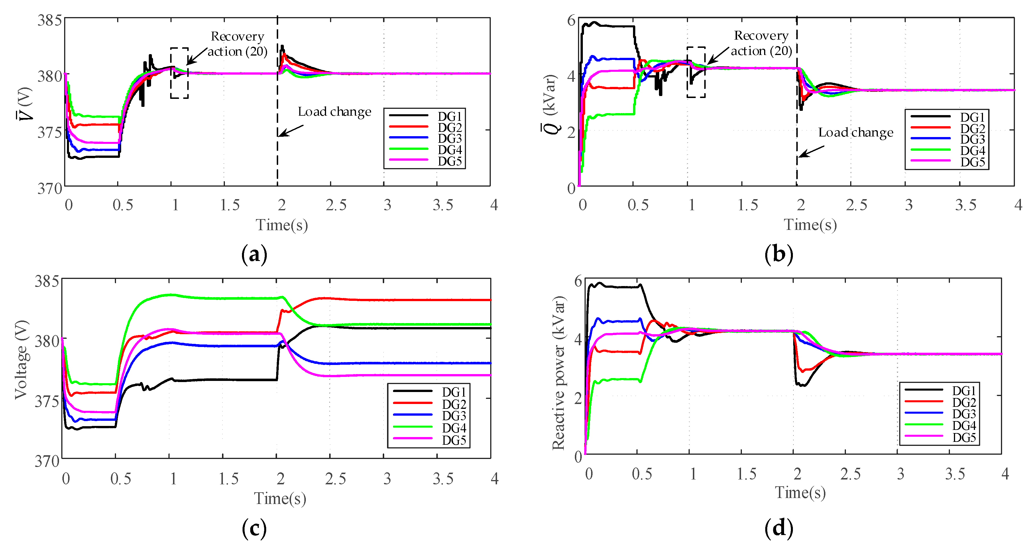
5.1. Transient Disturbance Scenario

In order to verify the effectiveness of the proposed resilient secondary control scheme under transient disturbance, the simulation process is designed as follows: (1) From t = 0 s, the microgrid works in islanded mode and only the primary control is activated for all five DGs. (2) At t = 0.5 s, the proposed secondary control scheme is applied. (3) At t = 0.7 s, the transient disturbance signals f 1 , V a ( k ) = r a n d   ( 0.5 ,   0.5 ) and f 1 , Q a ( k ) = r a n d   ( 500 ,   500 ) are injected into DG1 according to Equation (8). Then, the disturbance is cleared at t = 0.8s. (4) At t = 2 s, Load1 is reduced by the amount of 4kVar. The simulation results are shown in Figure 6.
Figure 6a,b show the evolutions of average estimates V ¯ ( k ) and Q ¯ ( k ) under transient disturbance and load changes. Figure 6c,d show the evolutions of DG output voltages and reactive power. Figure 6e shows the common trust value of DG1 which obtained by the proposed group decision-making process. Figure 6f shows the deviations of the collective estimation error which is calculated according to Equation (18). As can be seen that when the broadcast information V ¯ 1 ( k ) and Q ¯ 1 ( k ) of DG1 are affected by the transient disturbance, the common trust value of DG1 starts to decrease from t =0.7 s. Meanwhile, the neighbors of DG1 activate the discarding information mechanism, which prevents the propagation of the false data in the secondary control level. The collective estimation error of overall DGs is not equal to zero due to the presence of disturbance. When the disturbance is removed at t = 0.8 s, the common trust value of DG1 starts to increase. At t = 1.02 s the common trust value increases above the rejoining threshold T H = 0.9 , DG1 is re-identified as the normal DG by its neighbors. The recovery action according to Equation (20) is taken by DG1 and its neighbors. Consequently, the collective estimation error becomes zero due to the recovery action, which ensures the correct estimation of average voltage and reactive power. As seen in Figure 6c,d, the proposed resilient control scheme is able to restore the average voltages to the rated value 380V while maintaining the accurately reactive power sharing under transient disturbance. Furthermore, when the load changes at t = 2 s, the common trust value of DG1 is not affected by such change. It can be concluded that our approach can successfully differentiate between the false data injection and the normal load change.
To further explain the necessity of the proposed recovery action Equation (20), a case study is also done only with the discarding information mechanism. As can be seen in Figure 7a,b, although the discarding information mechanism prevents the propagation of false data, the average estimates V ¯ ( k ) and Q ¯ ( k ) cannot converge to the correct values without the recovery action Equation (20). Due to the adverse effects of false data, V ¯ ( k ) converges to the incorrect stable point 380.55 V while Q ¯ ( k ) abnormally increases from 4.2 kVar to 4.39 kVar. From Figure 7f, it can be easily seen that the collective estimation error is still not equal to zero even when the disturbance is cleared and DG1 rejoins the cooperative network at t = 1.02 s. It is concluded that the control objectives of average voltage restoration and reactive power sharing cannot be achieved without the recovery action Equation (20). Under such circumstance, the false data may lead to the abnormal changes of DGs’ output voltages and the circulating currents between different DGs which disrupts the stability and performance of the islanded microgrid.

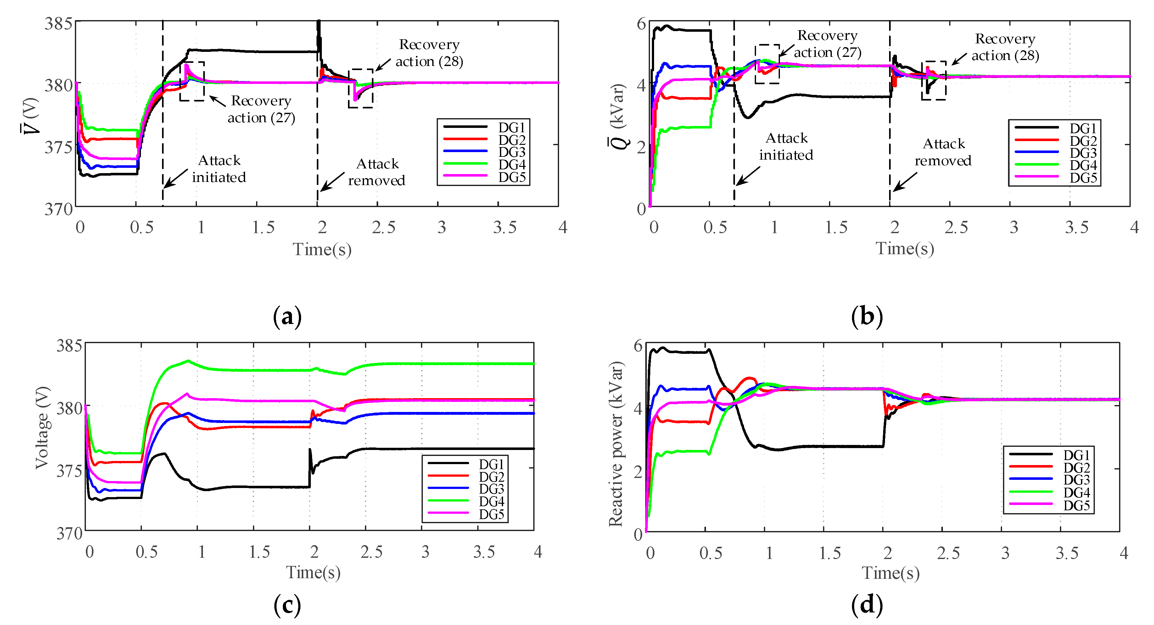
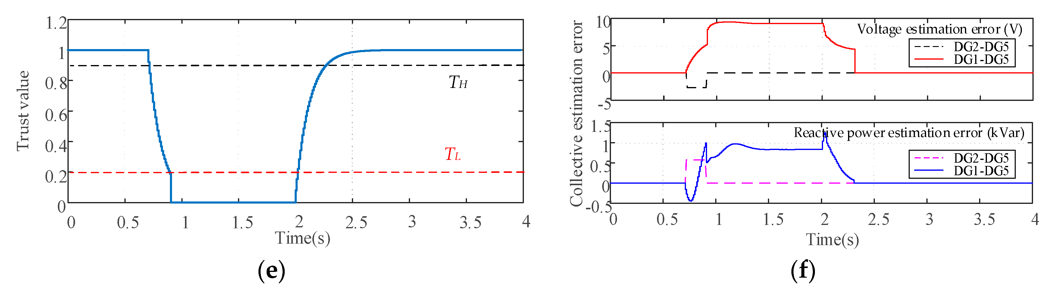
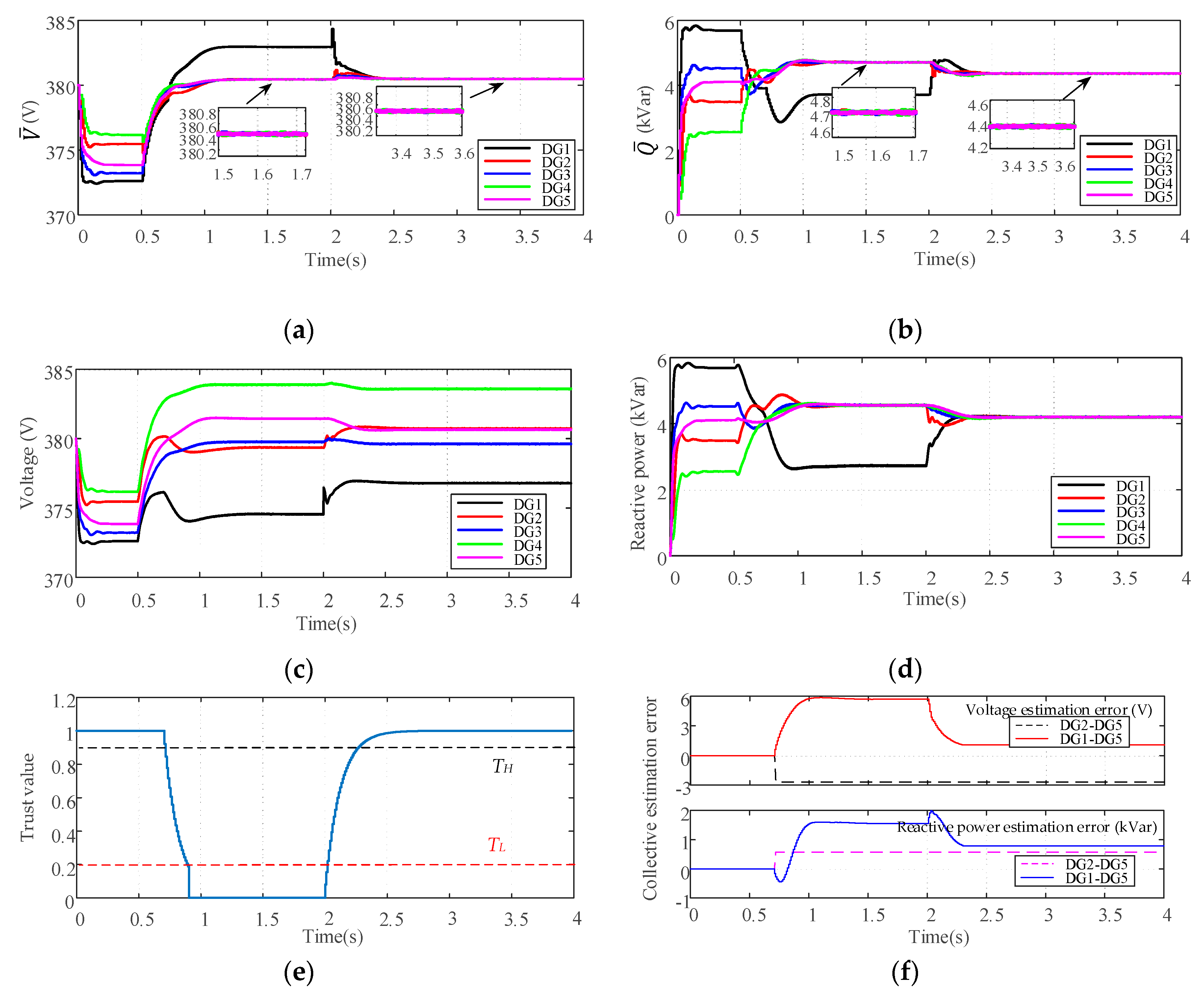
5.2. Continuous FDI Attack Scenario

In this case study, the effectiveness of the proposed resilient control scheme under continuous FDI attack is verified. At t = 0.7 s, the attack signals f 1 , V a ( k ) = 0.5 and f 1 , Q a ( k ) = 200 are injected into DG1 according to Equation (8). Then, the injected false data is removed by the attacker at t = 2 s and the system returns to secure. Other simulation process is similar with the case study under transient disturbance. The simulation results are demonstrated in Figure 8.
Figure 8 shows the resilience of the proposed control scheme in the continuous FDI attack scenario. As illustrated in Figure 8e, when the attacker starts to inject false data in DG1, the common trust value of DG1 keeps decreasing. When the common trust value reaches the isolation threshold T L = 0.2 at t = 0.9 s, the outgoing communication links of DG1 are deactivated and the recovery action is taken by the neighbors of DG1 according to Equation (27). It can be seen from Figure 8f that, the collective estimation error of the remaining normal DGs (DG2 to DG5) becomes zero after the recovery action Equation (27). Consequently, the remaining normal DGs can still converge to the desired stable point, without considering the attacked DG1 in the operation, which is illustrated in Figure 8a,b. After the attacker terminates the attack activity at t = 2 s, the common trust value of DG1 starts to increase. When the common trust value increases above the rejoining threshold T H = 0.9 at t = 2.31 s, DG1 is re-identified as the normal DG and the recovery action is taken by DG1 and its neighbors according to Equation (28). At that moment, we can see from Figure 8f that the collective estimation error of all normal DGs (DG1 to DG5) becomes zero due to the effects of the recovery action Equation (28). Since all DGs are considered as normal, the correct average estimates of voltages and reactive power can be gradually obtained in a distributed manner, as shown in Figure 8a,b. Thus, the control objectives of average voltage restoration and reactive power sharing are not affected by the continuous FDI attack with our control scheme, which can be seen from Figure 8c,d.
A case study is also conducted to show the effectiveness and necessity of the proposed recovery actions Equations (27) and (28). Figure 9 shows the evolution of the variables under continuous FDI attack only with the discarding information mechanism. As shown in Figure 9a, without the recovery action Equation (27), the average estimate V ¯ ( k ) obtained by the remaining normal DGs converges to the incorrect stable point 380.45 V even after the compromised DG1 is isolated from t = 0.9 s. And after the false data is removed from t =2 s, the average estimate V ¯ ( k ) converges to 380.50 V which causes the abnormal voltages rise of all DGs, as shown in Figure 9c. The similar abnormal changes in the average estimate Q ¯ ( k ) and DGs output reactive power also can be seen from Figure 9b,d. It can be easily seen from Figure 9f that, without the recovery action Equation (27), the collective estimation error of the remaining normal DGs is not equal to zero although DG1 is isolated from the network. When DG1 rejoins the network at t = 2.31 s, the collective estimation error is still not equal to zero without the recovery action Equation (28). It can be concluded that the correct average estimates cannot be obtained without the recovery actions Equations (27) and (28), which adversely affects the performance of the microgrid system in the continuous FDI attack scenario.

5.3. Multiple Attakers and Colluding Attack Scenario

In this case study, DG1 and DG4 are assumed to be attacked to test the robustness of the proposed control scheme in the multiple attackers scenario. At t = 0.7 s, the attack signals f 1 , V a ( k ) = 0.3 and f 1 , Q a ( k ) = 100 are injected into DG1, while the attack signals f 4 , V a ( k ) = 0.3 and f 4 , Q a ( k ) = 100 are injected into DG4, respectively. At t = 2.5 s, all the attack signals are cleared. It can be seen that the cumulative effect of the attack signals is zero, which satisfies the condition given by Equation (13). Thus, this case study also can verify the effectiveness of the proposed control scheme under probing attack. Furthermore, to valid the resistance of the proposed approach to colluding attack, the trust index T 43 ( k ) which represents DG3’s attitude about DG4 is manipulated by the colluding attacker from t = 0.8 s. The simulation results are illustrated in Figure 10.
As shown in Figure 10a,b, the average voltage and reactive power estimates of the remaining normal DGs (DG2, DG3 and DG5) can still converge to the desired consensus values under the effect of the recovery action Equation (27), when DG1 and DG4 are attacked from t = 0.7 s. After the attackers terminate the attack activity at t = 2 s, all DGs are considered as normal, and the recovery action Equation (28) makes the average estimates of all normal DGs converge to the correct values. Consequently, from Figure 10c,b we can see that the control objectives of average voltage restoration and reactive power sharing can be achieved with the proposed control scheme. From Figure 10e, it can be seen that both malicious DGs are detected by the trust-based detection mechanism, as the common trust values of DG1 and DG4 continue to drop from t = 0.7 s. It should be noted that although DG3’s attitude toward DG4 are manipulated by the colluding attacker from t = 0.8 s, the group decision-making mechanism is able to ensure the correct common trust value of DG4. According to the common trust value, DG4 is identified as the malicious DG by its neighbor at t = 0.9 s, and the adverse impact of false data can be eliminated by the recovery action Equation (27) when DG4 is isolated from the cooperative network. After the attack is cleared at t = 2.5 s, the common trust values of DG1 and DG4 keep increasing. Then, DG1 and DG4 are identified as normal DGs when the common trust values increase above the rejoining threshold. As shown in Figure 10f, the deviation of the collective estimation error of DG2, DG3 and DG5 starts from t = 0.7 s, because the broadcast information of DG1 and DG4 is discarded by their neighbors. Later, when DG1 and DG4 are isolated from the network, the collective estimation error of DG2, DG3 and DG5 becomes zero due to the recovery action Equation (27). It also can be seen from Figure 10f that, when the attack is removed and all DGs are considered as normal, the recovery action Equation (28) can successfully correct the collective estimation error of all DGs.

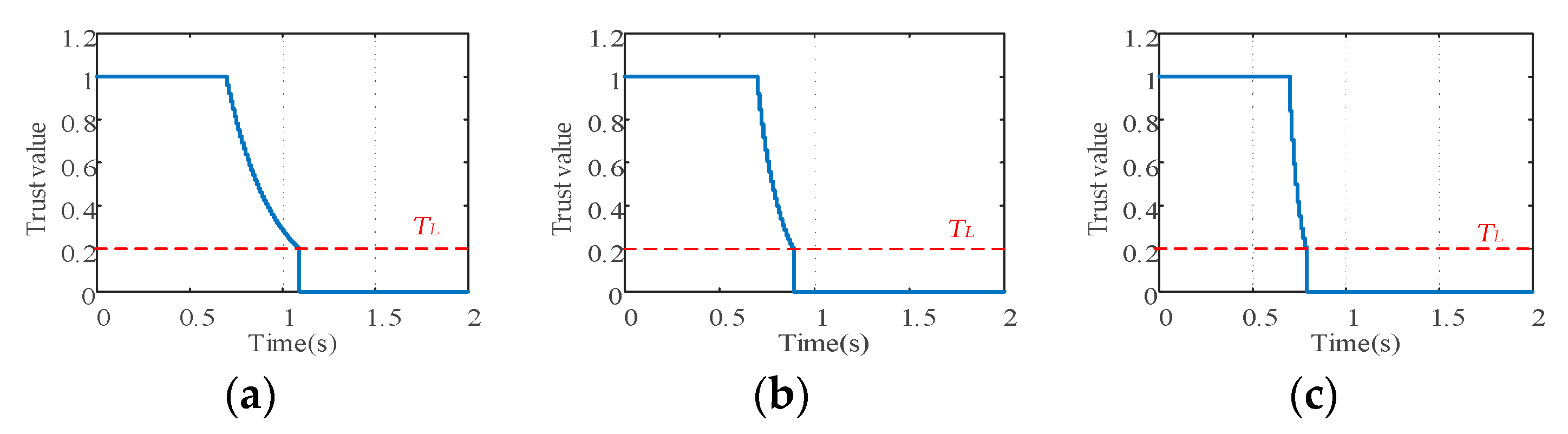
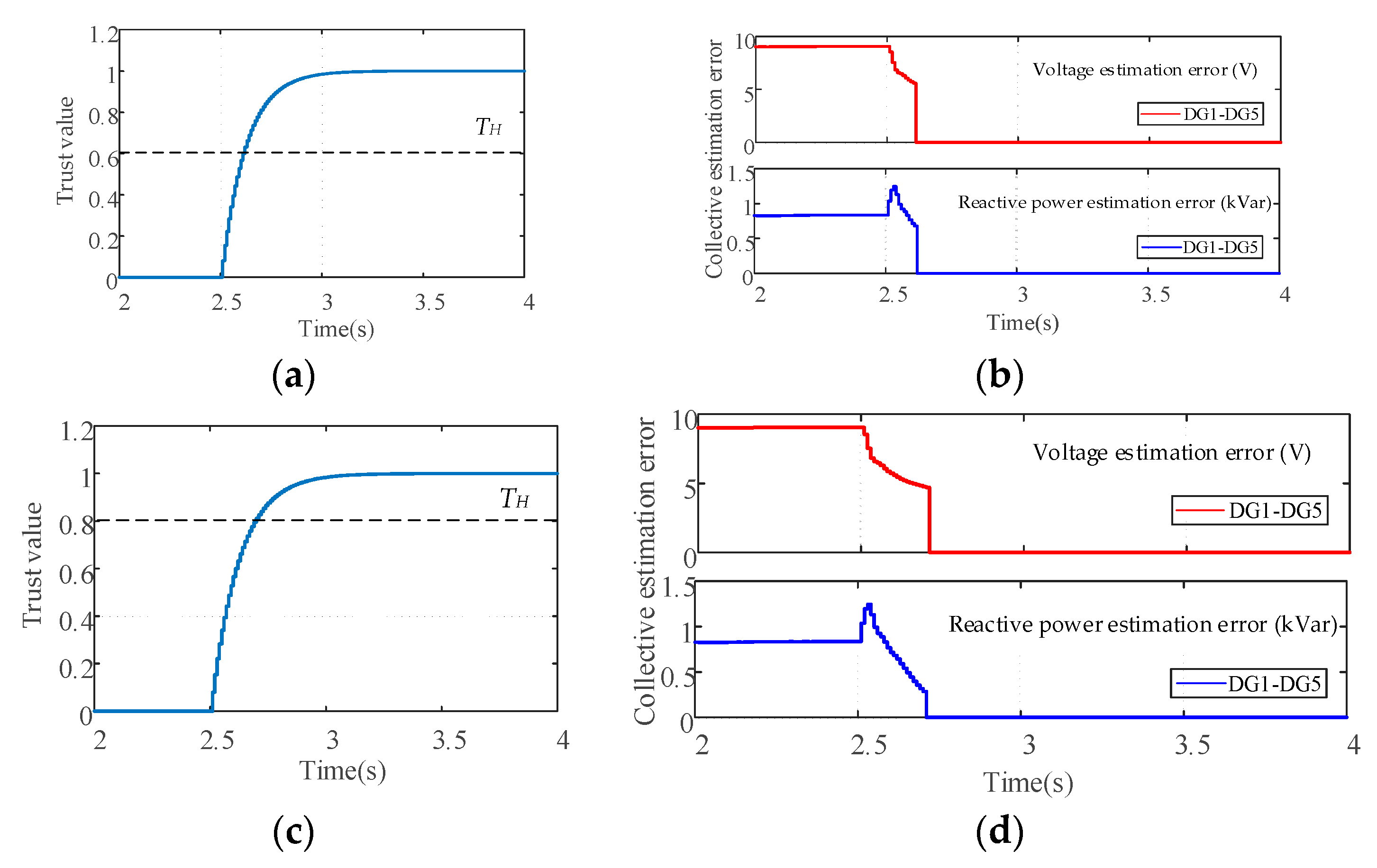
5.4. Impacts of Parameter Selection on the Performance of Resilient Control Scheme

In this subsection, the impacts of the parameter selection on the performance of the proposed control scheme are investigated. It is assumed that the attack signals f 1 , V a ( k ) = 0.5 and f 1 , Q a ( k ) = 200 are injected into DG1 according to Equation (8) from t = 0.7 s. Then, the attack is removed at t = 2.5 s. Figure 11 shows the impacts of sensitivity factor α on the common trust value of DG1. Figure 12 and Figure 13 show the evolutions of DG1’s common trust value and the collective estimation error under different isolation threshold T L and rejoining threshold T H .
As can be seen from Figure 11, with the increase of sensitivity factor α , the decline rate of common trust value will increase. Since the attacked DG will be isolated from the network when the common trust value drops below the isolation threshold, a smaller sensitivity factor can improve the tolerance of the proposed control scheme to the transient disturbance before a DG is identified as malicious. However, if the sensitivity factor is too small, the neighbors will spend more time to determine the malicious DG, which reduces the quickness of the detection process.
Figure 12 and Figure 13 show the evolutions of the collective estimation error under different isolation threshold T L and rejoining threshold T H where the sensitivity factor α is chosen as 0.08. From Figure 12, we can see that the deviation of the collective estimation error of DG2 to DG5 starts from t = 0.7 s due to the discarding information mechanism. When the common trust value drops below the isolation threshold T L , the collective estimation error will be corrected by the recovery action Equation (27). It can be seen that the isolation threshold only affects the duration of the deviation, while the magnitudes of deviation are the same. From Figure 13, we can see that after the attack is cleared at t = 2.5 s, the deviation of the collective estimation error of all normal DGs will be corrected by the recovery action Equation (28) when the common trust value increases above the rejoining threshold T H . Although a smaller T H can reduce the duration of deviation of collective estimation error, it also increases the risk that an attacked DG will be misidentified as a normal one. It can be concluded that the smaller isolation threshold T L and rejoining threshold T H represent a more tolerant attitude to FDI attack, but it also increase the duration of the collective estimation error and the missed detection rate of the proposed control scheme.

5.5. Scalability Test of the Resilient Control Scheme

This study case investigates the scalability of the proposed resilient control scheme with a modified test microgrid system which is similar with the model in [9]. Figure 14 shows the electrical network and communication topology of the islanded microgrid system. The microgrid is composed of 10 DGs, and the related specifications of the model are listed in Table A1 in the Appendix A.
As illustrated in Figure 14, DG1 and DG3 are photovoltaics (PVs), while DG6 and DG8 are wind turbines (WTs). PVs and WTs are not equipped with any storage device and operate in grid-feeding mode. This is standard practice and means that PVs and WTs are uncontrollable units, and they produce fixed amount of active power and no reactive power to the microgrid system, that is Q 1 = Q 3 = Q 6 = Q 8 = 0 [3,9]. Hence, the network possesses a total of six controllable DGs, e.g., micro gas turbine, and they are controlled by the proposed resilient control scheme. From t = 0 s, the microgrid works in islanded mode. At t = 1 s the secondary controller is applied and DG2 is under transient disturbance from 1.2s to 1.35s. The attack signals f 7 , V a ( k ) = 0.7 and f 7 , Q a ( k ) = 150 are injected into DG7 from t = 2.5 s and removed at t = 3.5 s. The simulation results are demonstrated in Figure 15.
As can be seen in Figure 15, the proposed trust-based control scheme is able to eliminate the collective estimation errors caused by the transient disturbance or the FDI attack, which makes the average voltage and reactive power estimates converge to the correct consensus values. Thus, the objective of voltage restoration and reactive power sharing can still be achieved in both disturbance and attack scenarios, which verifies the scalability and resilience of the proposed control scheme.

6. Conclusions

In this work, a trust-based control scheme is developed in order to improve the resilience of the voltage and reactive power control of an islanded AC microgrid subject to FDI attack. The adverse impacts of FDI attack are described in detail according to the cumulative effects of injected signals, and the proposed resilient control scheme is tested in various attack scenarios.
The validation of the proposed method is carried out through simulations using MATLAB/Simulink toolbox. In both transient disturbance and continuous attack scenarios, the results have proved that the forward-backward criterion is able to detect the misbehaving DGs, and using the discarding information mechanism with the proposed recovery actions can prevent the propagation of false data as well as eliminate the collective estimation errors in the secondary controller of islanded microgrids. The proposed method is compared with the scheme only using the discarding information mechanism to prove that the recovery actions are necessary to maintain the correct average estimates of voltage and reactive power. The capability to resist colluding attack and the scalability advantage of the proposed methods are also verified by case studies.
It can be obviously concluded that the proposed method can improve the resilience of the islanded microgrid, which ensures the average voltage restoration and reactive power sharing under FDI attack. In the future research, we will focus on the improvements of the trust-based control scheme while reducing the computation and communication burden.

Author Contributions

G.X. provided theoretical guidance. L.M. designed the trust-based resilient control scheme for the islanded microgrid and did the simulations to verify the effectiveness. All authors have read and agreed to the published version of the manuscript.

Funding

This work was supported by the Fundamental Research Funds for the Central Universities (2019QN111).

Conflicts of Interest

The authors declare no conflict of interest.

Appendix A

Table A1. Parameter values for simulation.
DG2, DG4, DG10DG5, DG7, DG9
R f = 0.1   Ω L f = 1.35   mH R f = 0.1   Ω L f = 1.35   mH
R c = 0.02   Ω L c = 2   mH R c = 0.04   Ω L c = 2   mH
m P = 9.42 × 10 5 n Q = 1.3 × 10 3 m P = 12.56 × 10 5 n Q = 1.5 × 10 3
K P V = 0.1 K I V = 420 K P V = 0.05 K I V = 390
K P C = 15 K I C = 20,000 K P C = 10.5 K I C = 16,000
Line Impedance
0.642 + j 0.083   Ω / km
Secondary Control Parameters
K P V A V E = 0.001 K I V A V E = 8 K P C A V E = 0.0001 K I C A V E = 0.025 ε = 0.06
Trust Evaluation Parameters
α = 0.08 T L = 0.2 T H = 0.9

References

  1. Kabalci, Y. A survey on smart metering and smart grid communication. Renew. Sust. Energ. Rev. 2016, 57, 302–318. [Google Scholar] [CrossRef]
  2. Han, Y.; Zhang, K.; Li, H.; Coelho, E.A.A.; Guerrero, J.M. Mas-based distributed coordinated control and optimization in microgrid and microgrid clusters: A comprehensive overview. IEEE Trans. Power Electron. 2018, 33, 6488–6508. [Google Scholar] [CrossRef] [Green Version]
  3. Schiffer, J.; Seel, T.; Raisch, J.; Sezi, T. Voltage stability and reactive power sharing in inverter-based microgrids with consensus-based distributed voltage control. IEEE Trans. Control Syst. Technol. 2016, 24, 96–109. [Google Scholar] [CrossRef] [Green Version]
  4. Carpintero-Rentería, M.; Santos-Martín, D.; Guerrero, J.M. Microgrids literature review through a layers structure. Energies 2019, 12, 4381. [Google Scholar] [CrossRef] [Green Version]
  5. Guerrero, J.M.; Vasquez, J.C.; Matas, J.; De Vicuna, L.G.; Castilla, M. Hierarchical control of droop-controlled AC and DC microgrids—A general approach toward standardization. IEEE Trans. Ind. Electron. 2010, 58, 158–172. [Google Scholar] [CrossRef]
  6. Tran, Q.T.T.; Luisa Di Silvestre, M.; Riva Sanseverino, E.; Zizzo, G.; Pham, T.N. Driven primary regulation for minimum power losses operation in islanded microgrids. Energies 2018, 11, 2890. [Google Scholar] [CrossRef] [Green Version]
  7. Isa, N.M.; Tan, C.W.; Yatim, A.H.M. A comprehensive review of cogeneration system in a microgrid: A perspective from architecture and operating system. Renew. Sust. Energ. Rev. 2018, 81, 2236–2263. [Google Scholar] [CrossRef]
  8. Sonam, S.; Bidyadhar, S.; Susmita, D. Distributed voltage and frequency synchronisation control scheme for islanded inverter-based microgrid. IET Smart Grid 2018, 1, 48–56. [Google Scholar]
  9. Chen, F.; Chen, M.; Li, Q.; Meng, K.; Guerrero, J.M.; Abbott, D. Multiagent-based reactive power sharing and control model for islanded microgrids. IEEE Trans. Sustain. Energy 2016, 7, 1232–1244. [Google Scholar] [CrossRef] [Green Version]
  10. Simpson-Porco, J.W.; Shafiee, Q.; Dörfler, F.; Vasquez, J.C.; Guerrero, J.M.; Bullo, F. Secondary frequency and voltage control of islanded microgrids via distributed averaging. IEEE Trans. Ind. Electron. 2015, 62, 7025–7038. [Google Scholar] [CrossRef]
  11. Abhinav, S.; Schizas, I.D.; Lewis, F.L.; Davoudi, A. Distributed noise-resilient networked synchrony of active distribution systems. IEEE Trans. Smart Grid 2018, 9, 836–884. [Google Scholar] [CrossRef]
  12. Mahmoud, M.S.; Hamdan, M.M.; Barudi, U.A. Modeling and control of cyber-physical systems subject to cyber attacks: A survey of recent advances and challenges. Neurocomputing 2019, 338, 101–105. [Google Scholar] [CrossRef]
  13. Chlela, M.; Joos, G.; Kassouf, M. Impact of cyber-attacks on islanded microgrid operation. In Proceedings of the Workshop on Communications, Computation and Control for Resilient Smart Energy Systems RSES ’16, New York, NY, USA, 21–24 June 2016. [Google Scholar]
  14. Deng, R.; Zhuang, P.; Liang, H. CCPA: Coordinated cyber-physical attacks and countermeasures in smart grid. IEEE Trans. Smart Grid 2017, 8, 2420–2430. [Google Scholar] [CrossRef]
  15. Zhao, C.; He, J.; Cheng, P.; Chen, J. Analysis of consensus-based distributed economic dispatch under stealthy attacks. IEEE Trans. Ind. Electron. 2017, 64, 51107–55117. [Google Scholar] [CrossRef]
  16. Rahman, M.A.; Mohsenian-Rad, H. False data injection attacks with incomplete information against smart power grids. In Proceedings of the 2012 IEEE Global Communications Conference (GLOBECOM), Anaheim, CA, USA, 3–7 December 2012. [Google Scholar]
  17. Liang, G.; Zhao, J.; Luo, F.; Weller, S.R.; Dong, Z.Y. A review of false data injection attacks against modern power systems. IEEE Trans. Smart Grid 2017, 8, 1630–1638. [Google Scholar] [CrossRef]
  18. Qi, J.; Taha, A.F.; Wang, J. Comparing kalman filters and observers for power system dynamic state estimation with model uncertainty and malicious cyber attacks. IEEE Access 2018, 6, 77155–77168. [Google Scholar] [CrossRef]
  19. Zhao, J.; Zhang, G.; La Scala, M.; Dong, Z.Y.; Chen, C.; Wang, J. Short-term state forecasting-aided method for detection of smart grid general false data injection attacks. IEEE Trans. Smart Grid 2017, 8, 1580–1590. [Google Scholar] [CrossRef]
  20. Wang, H.; Ruan, J.; Ma, Z.; Zhou, B.; Fu, X. Deep learning aided interval state prediction for improving cyber security in energy internet. Energy 2019, 174, 1292–1304. [Google Scholar] [CrossRef]
  21. James Ranjith, K.R.; Kundur, D.; Sikdar, B. Transient model-based detection scheme for false data injection attacks in microgrids. In Proceedings of the 2019 IEEE International Conference on Communications, Control, and Computing Technologies for Smart Grids (SmartGridComm), Beijing, China, 21–23 October 2019. [Google Scholar]
  22. Zhang, H.; Meng, W.; Qi, J.; Wang, X.; Zheng, W.X. Distributed load sharing under false data injection attack in an inverter-based microgrid. IEEE Trans. Ind. Electron. 2019, 66, 1543–1551. [Google Scholar] [CrossRef]
  23. Beg, O.A.; Johnson, T.T.; Davoudi, A. Detection of false-data injection attacks in cyber-physical DC microgrids. IEEE Trans. Ind. Electron. 2017, 13, 2693–2703. [Google Scholar] [CrossRef]
  24. Beg, O.A.; Nguyen, L.V.; Johnson, T.T.; Davoudi, A. Signal temporal logic-based attack detection in DC microgrids. IEEE Trans. Smart Grid 2019, 10, 3585–3595. [Google Scholar] [CrossRef]
  25. Abhinav, S.; Modares, H.; Lewis, F.L.; Ferrese, F.; Davoudi, A. Synchrony in networked microgrids under attacks. IEEE Trans. Smart Grid 2018, 9, 6731–6741. [Google Scholar] [CrossRef]
  26. Chen, L.; Wang, Y.; Lu, X.; Zheng, T.; Wang, J.; Mei, S. Resilient active power sharing in autonomous microgrids using pinning-consensus-based distributed control. IEEE Trans. Smart Grid 2019, 10, 6802–6811. [Google Scholar] [CrossRef]
  27. Zeng, W.; Chow, M. Resilient distributed control in the presence of misbehaving agents in networked control systems. IEEE Trans. Cybern. 2014, 44, 2038–2049. [Google Scholar] [CrossRef] [PubMed]
  28. Ren, J.; Zhang, Y.; Ye, Q.; Yang, K.; Zhang, K.; Shen, X.S. Exploiting secure and energy efficient collaborative spectrum sensing for cognitive radio sensor networks. IEEE Trans. Wirel. Commun. 2016, 15, 6813–6827. [Google Scholar] [CrossRef]
  29. Singh, K.; Verma, A.K. FCTM: A novel fuzzy classification trust model for enhancing reliability in flying Ad hoc networks (FANETs). Ad Hoc Sens. Wirl. Netw. 2018, 40, 23–47. [Google Scholar]
  30. Zhu, M.; Martínez, S. Discrete-time dynamic average consensus. Automatica 2010, 46, 322–329. [Google Scholar] [CrossRef]
  31. Shafiee, Q.; Guerrero, J.M.; Vasquez, J.C. Distributed secondary control for islanded microgrids—A novel approach. IEEE Trans. Power Electron. 2014, 29, 1018–1031. [Google Scholar] [CrossRef] [Green Version]
  32. He, J.; Zhou, M.; Cheng, P.; Shi, L.; Chen, J. Consensus under bounded noise in discrete network systems: An algorithm with fast convergence and high accuracy. IEEE Trans. Cybern. 2016, 46, 2874–2884. [Google Scholar] [CrossRef]
  33. Zeng, W.; Chow, M. A reputation-based secure distributed control methodology in D-NCS. IEEE Trans. Ind. Electron. 2014, 61, 6294–6303. [Google Scholar] [CrossRef]
  34. Li, P.; Liu, Y.; Xin, H.; Jiang, X. A robust distributed economic dispatch strategy of virtual power plant under cyber-attacks. IEEE Trans. Ind. Inform. 2018, 14, 4343–4352. [Google Scholar] [CrossRef]
  35. Jones, G.; Vanderson, B.; Otto, L.; Edson, S.; Jean-Paul, B.; Fabrício, E. Trust and reputation models for multi-agent systems. ACM Comput. Surv. 2015, 48, 1–42. [Google Scholar]
  36. Hao, Y.; Cheng, Y.; Zhou, C.; Song, W. A distributed key management framework with cooperative message authentication in VANET. IEEE J. Sel. Areas Commun. 2011, 29, 616–629. [Google Scholar] [CrossRef]
  37. Zhang, Q.; Yu, T.; Ning, P. A framework for identifying compromised nodes in wireless sensor networks. ACM Trans. Inf. Syst. Secur. 2008, 11, 1–37. [Google Scholar] [CrossRef]
Figure 1. Cyber-physical model of an islanded microgrid.
Energies 13 03828 g001
Figure 2. Proposed cooperative control for average voltage restoration and reactive power sharing.
Energies 13 03828 g002
Figure 3. The different adverse effects of FDI attack on the proposed cooperative controller: (a) Average voltage estimate; (b) Average reactive power estimate; (c) Voltages of DGs; (d) Reactive power of DGs.
Energies 13 03828 g003
Figure 4. Illustration of colluding attack on the trust evaluation process.
Energies 13 03828 g004
Figure 5. Islanded microgrid test system: (a) Physical model; (b) Communication topology.
Energies 13 03828 g005
Figure 6. Performance of the proposed control scheme under transient disturbance: (a) Average voltage estimates; (b) Average reactive power estimates; (c) Voltages of DGs; (d) Reactive power of DGs. (e) Common trust value of DG1; (f) Collective estimation error.
Energies 13 03828 g006aEnergies 13 03828 g006b
Figure 7. Performance of the control scheme only with the discarding information mechanism: (a) Average voltage estimates; (b) Average reactive power estimates; (c) Voltages of DGs; (d) Reactive power of DGs. (e) Common trust value of DG1; (f) Collective estimation error.
Energies 13 03828 g007
Figure 8. Performance of the proposed control scheme under continuous FDI attack: (a) Average voltage estimates; (b) Average reactive power estimates; (c) Voltages of DGs; (d) Reactive power of DGs. (e) Common trust value of DG1; (f) Collective estimation error.
Energies 13 03828 g008aEnergies 13 03828 g008b
Figure 9. Performance of the control scheme only with the discarding information mechanism: (a) Average voltage estimates; (b) Average reactive power estimates; (c) Voltages of DGs; (d) Reactive power of DGs. (e) Common trust value of DG1; (f) Collective estimation error.
Energies 13 03828 g009
Figure 10. Performance of the proposed control scheme with multiple attackers and colluding attack: (a) Average voltage estimates; (b) Average reactive power estimates; (c) Voltages of DGs; (d) Reactive power of DGs. (e) Common trust values of DG1 and DG4; (f) Collective estimation error.
Energies 13 03828 g010aEnergies 13 03828 g010b
Figure 11. Impacts of sensitivity factor α on the common trust value of DG1: (a) α = 0.04 ; (b) α = 0.08 ; (c) α = 0.16 .
Energies 13 03828 g011
Figure 12. The impacts of isolation threshold T L on the collective estimation error: (a) DG1’s common trust value under T L = 0.5 ; (b) Collective estimation error of DG2 to DG5 under T L = 0.5 ; (c) DG1’s common trust value under T L = 0.1 ; (d) Collective estimation error of DG2 to DG5 under T L = 0.1 .
Energies 13 03828 g012
Figure 13. The impacts of rejoining threshold T H on the collective estimation error: (a) DG1’s common trust value under T H = 0.6 ; (b) Collective estimation error of all DGs under T H = 0.6 ; (c) DG1’s common trust value under T H = 0.8 ; (d) Collective estimation error of all DGs under T H = 0.8 .
Energies 13 03828 g013
Figure 14. Modified microgrid test system: (a) Electrical network; (b) Communication topology.
Energies 13 03828 g014
Figure 15. Performance of the control scheme under the scalability test: (a) Average voltage estimates; (b) Average reactive power estimates; (c) Voltages of DGs; (d) Reactive power of DGs. (e) Common trust values of DG2 and DG7; (f) Collective estimation error.
Energies 13 03828 g015
Table 1. Parameter values for simulation.
DG1 & DG2 (25 kW, 15 kVar)DG3 & DG4 & DG5 (20 kW, 12 kVar)
R f = 0.1   Ω L f = 1.35   mH R f = 0.1   Ω L f = 1.35   mH
R c = 0.03   Ω L c = 0.35   mH R c = 0.03   Ω L c = 0.35   mH
m P = 9.4 × 10 5 n Q = 1.3 × 10 3 m P = 12.5 × 10 5 n Q = 1.5 × 10 3
K P V = 0.1 K I V = 420 K P V = 0.05 K I V = 390
K P C = 15 K I C = 20,000 K P C = 10.5 K I C = 16,000
Line 1 &Line 3Line 2&Line 4
R l 1 = 0.23   L l 1 = 0.318   mH R l 2 = 0.35     L l 1 = 1.847   mH
Load 1Load 2Load 3
12kW + 10 kVar15 kW + 5 kVar6 kW + 6 kVar
Secondary Control Parameters
K P V A V E = 0.001 K I V A V E = 10 K P Q A V E = 0.0001 K I Q A V E = 0.03 ε = 0.1
Trust Evaluation Parameters
α = 0.08 T L = 0.2 T H = 0.9

