Abstract
The novelty behind the research in this paper is to investigate the Super Twisting Sliding Mode Controller (ST-SMC) for efficiently injecting both active and reactive power under normal and abnormal operating conditions for a three-phase grid-connected photovoltaic (PV) system. The ST-SMC is aimed to inject sinusoidal current to the grid with low Total Harmonic Distortion (THD), to avoid chattering with easy real implementation, and to enhance the quality of disturbance rejection and sensitivity to parameter variation. The test under normal conditions includes initialization, steady state behavior, dynamic behavior, and interrupting the injection of acting and reactive power while the abnormal conditions consists of voltage sag, voltage swell, frequency variation, DC-link variation, and inclusion of 5th harmonics, etc. The phase lock loop used for synchronization is based on a synchronous reference frame that works well under distorted grids and nonideal. Automatic code is generated in PSIM 9.1 for hardware implementation in the DSP board TMS32F28335 from Texas Instruments while code composer studio 6.2.0 is used for debugging. The real time testing is executed using Typhoon Hardware in Loop (HIL) 402 device on the DSP board. The results authenticate the fastness, effectiveness, and robustness for both steady state and dynamic behavior under various scenarios of the designed controller.
1. Introduction
Exponential decrease in fossil fuel, rapidly varying climate, and high electric power demand are currently severe problems due to the abruptly increasing population throughout the world. To fulfill the power demand, the alternative way is to adopt Renewable Energy Resources (RER) [1,2]. An abrupt growth has been seen in Solar Photovoltaic (SPV) system by the past several years; however, its importance will be further increased in the near future as its integration with the grid becomes more sophisticated [3,4,5]. The SPV system is considered one of the favorite RERs due to its abundance, low installation cost, good looks, and noiselessness as there are no rotating parts. The coupling of SPV with distribution substation are in major part and is known as a grid-connected PV system [4].
Generally, a grid-connected PV system is composed of PV array which takes solar irradiance as input and generates electric power as output and another part is power electronic-based converters, which are responsible for the extraction of power from PV array and interconnection with grid [6]. A series/parallel connection of PV cells makes a PV array whose output power depends on the irradiance and temperature of the sun [7]. A specific point is calculated through the P-V curve known as the Maximum Power Point (MPP) for different conditions of temperature and solar irradiance, at which power with high efficiency is received from the PV array [8]. The MPP can be located through an algorithm known as the Maximum Power Point Tracking (MPPT), by controlling a DC-DC converter. Different types of techniques are being used to acquire MPPT such as hill-climbing, incremental conductance, perturb and observe, and some others [9,10,11,12,13,14].
In the grid-connected PV system, converters are mostly used, which are composed of power electronic components [15], and time by time strict limitations have been imposed on grid-connected PV systems [16]. Due to non-linear and intermittency response of power-electronic converters, harmonics are usually associated with it. To overcome this problem, advanced and robust control schemes can be designed [17]. Mostly, a dual cascaded control scheme is used for a grid-connected PV system. To control the current feed-in to the grid, the inner current controller remains the main focal area for the researchers as it is associated with power quality issues [16]. However, for reference current generation, the outer-loop is used to control the DC-link voltage or power. The voltage and current of the grid should be in phase and synchronized, Phase Lock Loop (PLL) is mostly used for this purpose [18,19,20]. The signals given by PLL are very important for the current controller, as it is used throughout the control structure and conditioning [21,22].
Hence, the design of a current control structure that is robust, accurate, dynamic, and resilient towards grid faults according to grid codes is the key problem for researchers. Previously, different types of control strategies have been introduced to track nominal current and DC voltage for the grid-connected PV system. Conventionally, the PI controller has been used for electrical variables optimization due to its simplicity, minimum iterative variables, and easy implementation [23]. Still, the PI controller results in some issues such as sensitivity and low accuracy toward variable uncertainties and sudden faults. That is why researchers are looking the solution in nonlinear controllers such as Fuzzy Logic Controller (FLC), Neural Network (NN), Sliding Mode Controller (SMC), model predictive controller, deadbeat controller, repetitive controller, hysteresis controller, adaptive controller, neuro-fuzzy controller, feedback linearization technique [24,25,26,27,28,29,30,31,32,33,34,35,36,37,38,39,40,41,42,43,44,45], etc.
In [24], a predictive fuzzy logic-based energy management system was proposed for standalone and grid-connected operation of residential microgrids. A Legendre-based neural network controller for operation in grid-connected mode to improve the power quality is proposed in [25]. In [26], an artificial neural network-based vector controller is designed for the integration of residential solar PV with a utility grid. The controller reduces the harmonics contents and improves adaptivity under uncertainty. Rapid terminal SMC based on Lyapunov is presented for a hybrid system, i.e., PV and wind connected to the grid in [27]. This improves the performance under disturbances in the converter, inverter, and hybrid system. An Space Vector Modulation (SVM) based SMC for 3L-NPC inverter and integral SMC for grid-connected PV system is presented in [28] and [29], respectively. Each controller improves the control dynamics and tracking performance of the PV system. In [30] and [31], a fuzzy-SMC based on disturbance observer and sliding-mode voltage observer are presented, respectively. The design controllers handle the chattering and uncertainties effectively. In [32,33,34,35], MPC controllers are designed for a grid-connected PV system that improves both the dynamic and steady-state performance. In [36], an adaptive backstepping controller is designed for DC-side of Z-source inverter connected to the grid that guarantees stable and robust performance under variation in temperature and solar irradiance. A fractional repetitive control and multi-rate fractional order control are discussed, described, and designed in [37,38], respectively. The above controllers improve the control performance; however, they lack the analysis of ST-SMC under normal and abnormal conditions.
The SMC is a non-linear approach that has the remarkable features of easy tuning, robustness, accuracy, and insensitivity to uncertainties and external disturbances [46]. The main shortcomings of standard (first-order) SMC are chattering, which results in electromagnetic interference (EMI) noise and instability issues. First-order SMC with sign function is replaced by a smooth function, such as the practical saturation function [47], sigmoid function [48], or ideal saturation function [49], to tackle the chattering problem. However, they suffer from the degradation of tracking performance and robustness. To overcome this, several approaches are developed; higher order SMC is one of the alternatives to overcome chattering [50]. The information demand increases in the higher order SMC, which is the main problem in its implementation. The Super Twisting SMC (ST-SMC) is one of higher order SMC that does not require additional information [51]. The ST-SMC has become a benchmark for the second-order SMC, it has the capability of chattering reduction even in the presence of uncertainties, finite-time convergence to the sliding surface, easy real-time implementation, and system robust stabilization [52]. Moreover, it converges the system states to the sliding variable abruptly. In this paper, ST-SMC is designed for a three-phase grid-connected PV system to efficiently injected active and reactive power under various normal and abnormal perturbations.
The main contributions of the manuscript are listed below:
- Design of the ST-SMC for efficiently injecting both active and reactive power to the utility grid.
- Mathematically modeling of the three-phase grid-connected PV system in a comprehensive manner.
- Employing the SRF-PLL that works accurately under distorted and nonideal grids.
- HIL testing under normal conditions that includes initialization, steady-state behavior, dynamic behavior, and interrupting the injection of acting and reactive power.
- Testing under abnormal conditions, i.e., voltage sag, voltage swell, frequency variation, DC-link variation, inclusion of 5th harmonics, etc.
The remaining of the paper is structured as follows: Section 2 provides the mathematical modeling, system design, and synchronous reference frame based phase lock loop for a three-phase grid-connected PV system; SMC and the design of ST-SMC are broadly outlined in Section 3; Section 4 assesses hardware in loop results for the grid-connected PV system under normal and abnormal perturbations; and finally, the paper is concluded in Section 5.
2. Grid-connected PV System
2.1. System Modeling
The control of the direct-quadrature (dq) synchronous reference frame is decoupled. It has a negligible steady state error and fast transient response [53]. The grid-connected PV system is normally controlled in dq frame. The three-phase line voltages provide the single-phase voltages of the inverter as:
In above Equation , are phase voltages in natural-frame and , are the line voltages. Additionally, using Clark’s transformation the three-phase voltages are converted into stationary reference-frame and [54]:
Next, Using Park’s transformation the and frame is transformed into synchronous or dq reference-frame:
In Equation (3), the synchronous frame axis is presented by a dq subscript. Using PLL, the synchronous frame angle is acquired [53]. Moreover, Equation (4) converts the current into a dq reference frame:
The active and reactive power of the inverter can be calculated using the dq components of currents and voltages:
Supposing that the grid voltage and current has zero phase shift, i.e., in phase, which gives = 0. Thus, the above Equation (5) can be expressed as:
The real power depends on and reactive power depends on , respectively.
2.2. System Description
The block diagram of the design system is presented in Figure 1, while Table 1 lists the nominal parameters. The proposed system has the capability to control both active and reactive power. The grid-connected mode is tested under normal and abnormal conditions. The capacity of the inverter is 15 kVA with the output voltage 120 VAC RMS and the DC-link voltage 380 V.
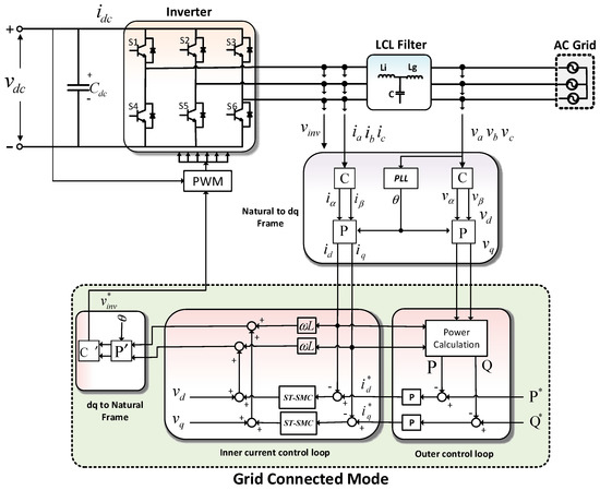
Figure 1.
Proposed model for grid-connected and standalone PV system.

Table 1.
Nominal Parameters of the System.
The type III controller-based DC-DC boost converter is assumed to supply 380 V whose input voltage is 80 V [55]. The LCL filter is used to connect the inverter with the grid [56,57]. The MPPT controller for RER or high-level energy management controller is utilized to set the and power references, respectively. For controller designed, Park and Clarke’s transformation based on dq theory is used to define control signals. The tuning of the d-axis well tune q-axis as the dynamics of both axes are similar [55]. The inverter is employed with Sinusoidal Pulse Width Modulation (SPWM) technique. Sliding mode Controller (SMC) based on the Super Twisting algorithm is designed to inject high quality fed in current into grid. This design will be discussed in the next section.
2.3. SRF-PLL Design
Currently, Phase Lock Loop (PLL) is widely used to synchronize PV plants to the power grid. The range of the PLL techniques is from a few hertz to gigahertz. There are three main PLL procedures for phase tracking, e.g., (a) zero-crossing based PLL, (b) stationary reference frame, and (c) Synchronous Reference Frame (SRF)-based PLL [54]. The SRF-PLL works accurately under distorted and nonideal grids and is applicable to both single phase and three-phase systems. The overall structure is presented in Figure 2. The voltage and are calculated from phase voltages , , using and transformation. The angle required in the transformation is computed by integrating the . The readers are encouraged for further details about PLL [54,55,58,59,60].
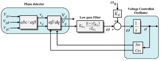
Figure 2.
Basic Synchronous Reference Frame based PLL structure.
3. Design of Super Twisting SMC
3.1. Sliding Mode Controller
In SMC, the systems states are driven toward Sliding Surface (SS) [61,62]. The graphical interpretation of SMC is presented in Figure 3 [62]. After reaching SS the SMC keeps the states on the close neighborhood of the SS. The design of SMC consists of two parts SS and control law design.
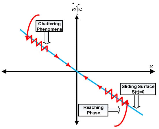
Figure 3.
Graphical interpretation of the sliding mode controller [62].
SS: A typical form for SS is given as follows:
where with equal to a relative degree between and . The choice of is an arbitrary positive constant. The selection of should be in such a way that gives a stable differential equation. For different values of the SS is given as follows:
Control law design: The second part is the control law design that should steer the variable to zero in finite time; in other words, should steer the system trajectories onto the sliding manifold. The control law will be either first order (conventional) or higher order SMC. The discontinuous function causes oscillation in various areas; using continuous functions and , some chattering is attenuated but the robustness is not maintained. An alternative solution is using higher order SMC that maintain robustness and completely solves the chattering issues. Table 2 presents the comparison of various first order SMCs based on continuous and discontinuous functions [61].

Table 2.
Comparison of various first-order SMC [61].
3.2. Super Twisting Sliding Mode Controller Design
Without affecting the tracking performance and to avoid chattering, the Super Twisting ST-SMC is a viable alternative to the standard first-order SMC particularly intended for systems with relative degree 1. After describing a trajectory similar to one of the Twisting algorithms, this algorithm converges in finite time with a proper choice of parameters [63]. In ST-SMC the trajectories are twisting around the origin on the 2-sliding plane as presented in Figure 4a. The ST algorithm is a nonlinear version of the conventional PI controller presented in Figure 4b. The ST-SMC is highly suitable for real implementation and more immune to output measurement noise and possible errors in the estimation of [64]. The ST-SMC control law is composed of two terms. The discontinuous time derivative defines the first term, while the second term is a continuous function of the available sliding variable, which is present during the reaching phase only. The following control law defines the control algorithm [63,65,66]:
where U is the control value boundary and is a boundary layer around the SS . The sufficient conditions for finite time convergence to the sliding mode manifold are:
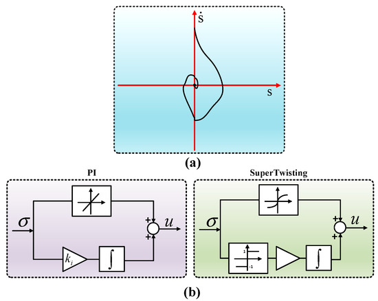
Figure 4.
(a) Phase trajectory of the Super Twisting algorithm [66] (b) comparison of Super Twisting controller with PI [61].
, , , are positive constants and , , are control gains.
When controlled systems are linearly dependent on the control, then and does not need to be bound [67]; thus, the final equation of the controller may be simplified as:
In Equation (13), and . Where is a positive constant with sufficiently large values, its value is tuned by using the “trial and error” method until good performance in closed-loop is achieved. The various values of controller constants are: , , and , and . The control law in Equation (13), used in the controller design, is stable and its step by step analysis of stability is given in [68,69].
4. Results and Discussion
4.1. Hardware in Loop
Leading to the results very near to practical conditions, Hardware in Loop (HIL) for the design of converters and control in power electronics has been gradually identified as an effective tool [70]. In grid-connected inverters, the practical implementation of some tests is difficult due to the fact they require alterations in the grid conditions or filter or in the inverter; this can be easily executed in HIL. In this paper, the effectiveness and the feasibility of ST-SMC are validated using a Hardware in Loop (Typhoon HIL) 402 device for real-time testing [71]. The power and control structure of Figure 1 is drawn in PSIM version 9.1. The code composer studio 6.2.0 is used for debugging the code, which is automatically generated using PSIM 9.1 using the overall test bench setup presented in Figure 5. The TMS32F28335 DSP board from Texas Instruments is used for validation. The u-grid interface 2.0 board is used for interface among HIL (from Typhoon manufacturer) and the results are captured using Tektronix oscilloscope TPS 2024B. The system is tested for grid-connected mode under various normal and abnormal conditions in different scenarios.
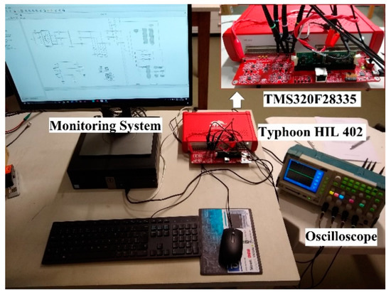
Figure 5.
Test bench setup for experimental results.
4.1.1. Normal Conditions
The voltage setting for channel 1, channel 2, and channel 3 are set 133.33 V/1 V division, while the current division is set for channel 1, channel 2, and channel 3 as 33.33 A/1 V. The voltage and currents sensor gains are set to ki = 0.03 and kv = 0.0075, correspondingly. Figure 6 presents a three-phase output current during initialization from Pref = 0 to Pref = 10 kW and Qref = 0 kVAr. Phase A, B, C are represented by yellow, blue, and magenta colors, respectively. The current reference abruptly reaches to its reference value by injecting the required power without distortions. Figure 7 shows three-phase output current in steady-state for Pref = 10 kW and Qref = 0 kVAr. The currents are smooth and symmetrical. Figure 8 describes the voltage and current for phase A during Pref = 0 to Pref = 10 kW and Qref = 0. The green color shows the voltage and yellow color shows the current for phase “A.” The current switches to its required value as soon as a step-in power is introduced, similar for Phase “B” and “C.” Thus, active power is injected. The currents and voltages are in phase authenticating the efficient performance of SRF-PLL. Figure 9 depicts the voltage and current for phase B during Pref = 0 to Pref = 10 kW. Figure 10 illustrates the voltage and current for phase C during Pref = 0 to Pref = 10 kW. The starting transient is negligible validating the robust performance of ST-SMC. Figure 11 demonstrates three-phase currents during stopping from Pref = 10 to Pref = 0 kW. The inverter is turned off and stops injecting active and reactive power. The response is faster during this case. Figure 12 represents the voltage and current for phase A during Qref = 0 to Qref = 10 kVAr and Pref = 0. A phase shift is introduced indicating the injection of reactive power. Figure 13 signifies the steady state of Fig10. There is no oscillation and transients during steady-state operation. Figure 14 elaborates the voltage and current for phase B during Qref = 0 to Qref = 10 kVAr and Pref = 0. A phase shift is noticed, whenever a step in reactive power is introduced, thus injecting reactive power as well. Figure 15 discusses the voltage and current for phase A during Pref = 10 kW and the transition from Qref = 0 to Qref = 15 kVar. Before the injection of reactive power, the current and voltages are in phase as soon as a step-in reactive power is produced, a phase shift in current and voltage is noted. Step A is clearly highlighted in red color. Similar is the case for phase “B” and “C.” Figure 16 introduces the voltage and current for phase B during Pref = 10 kW and the transition from Qref = 0 to Qref = 15 kVar. Figure 17 expresses the voltage and current for phase C during Pref = 10 kW and the transition from Qref = 0 to Qref = 15 kVar. The designed controller shows less sensitivity towards the sudden disturbance. In short, the performance of the designed controller is faster, accurate, efficient, and robust when tested under various scenarios.
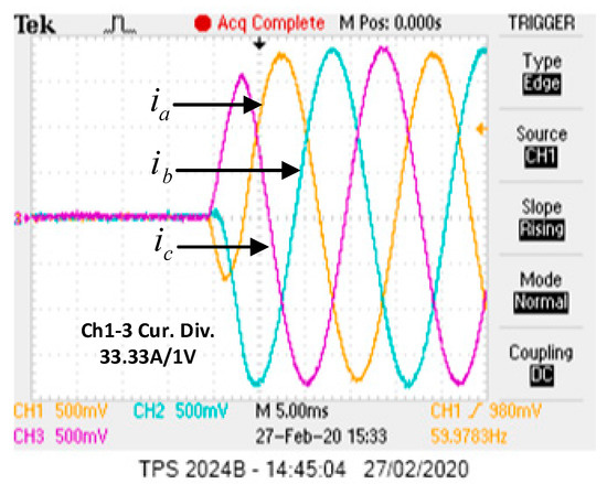
Figure 6.
Three-phase output current during initialization from Pref = 0 to Pref = 10 kW and Qref = 0 kVAr.
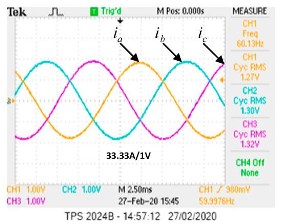
Figure 7.
Three-phase output current in steady state for Pref = 10 kW and Qref = 0 kVAr.
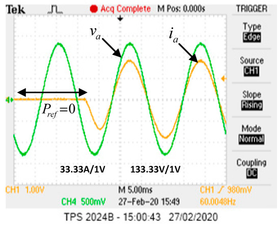
Figure 8.
Voltage and current for phase A during Pref = 0 to Pref = 10 kW and Qref = 0.
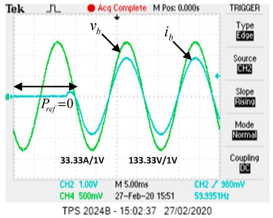
Figure 9.
Voltage and current for phase B during Pref = 0 to Pref = 10 kW.
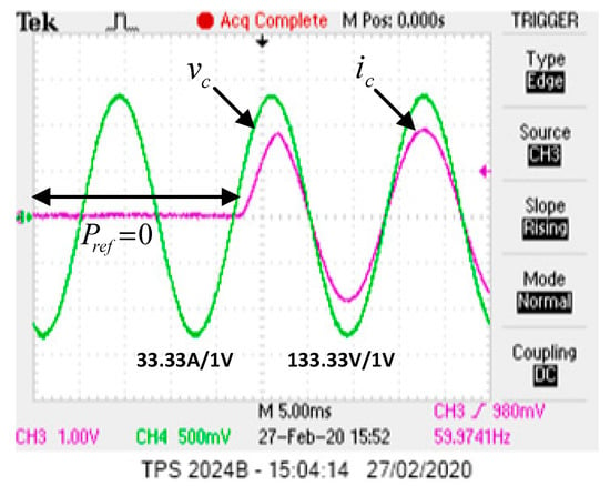
Figure 10.
Voltage and current for phase C during Pref = 0 to Pref = 10 kW.
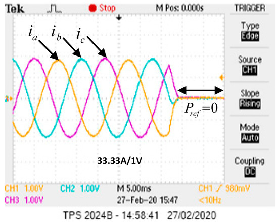
Figure 11.
Three-phase current during a stop from Pref = 10 kW to Pref = 0 kW.
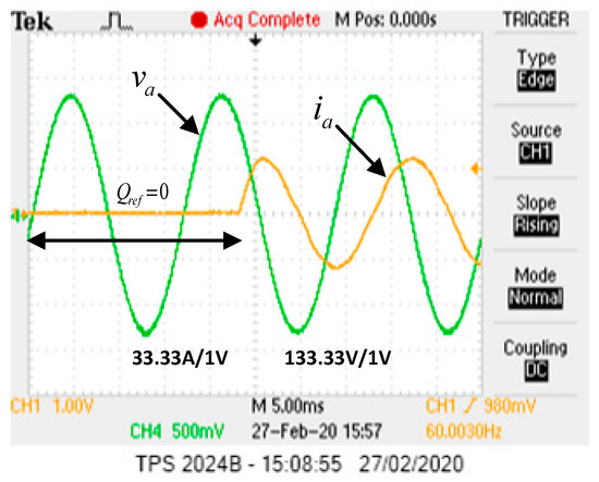
Figure 12.
Voltage and current for phase A during Qref = 0 to Qref = 10kVAr and Pref = 0.
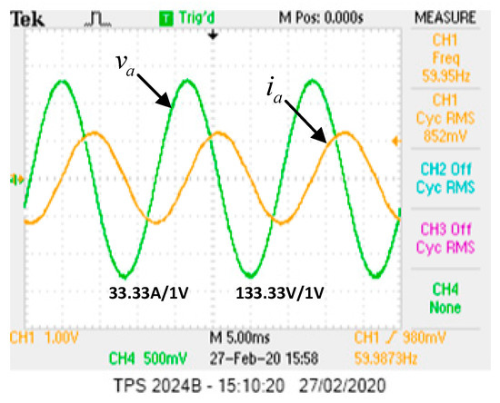
Figure 13.
Steady-state of Figure 12.
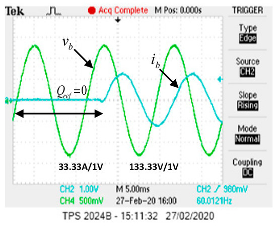
Figure 14.
Voltage and current for phase B during Qref = 0 to Qref = 10 kVAr and Pref = 0.
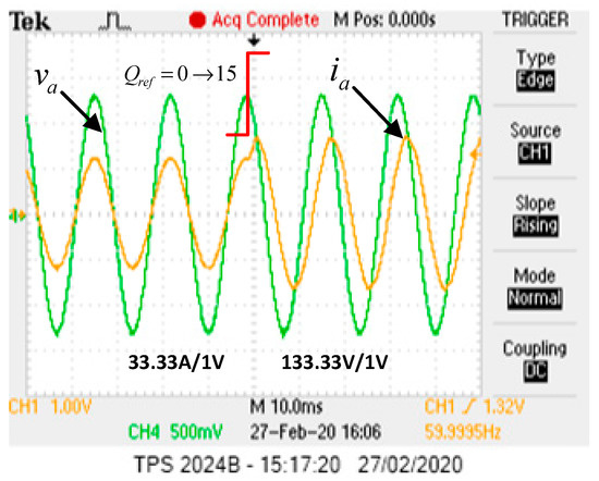
Figure 15.
Voltage and current for phase A during Pref = 10 kW and transition from Qref = 0 to Qref = 15 kVar.
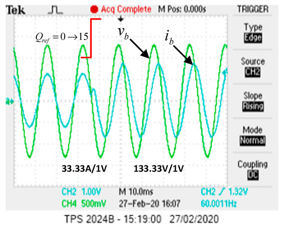
Figure 16.
Voltage and current for phase B during Pref = 10 kW and transition from Qref = 0 to Qref = 15 kVar.
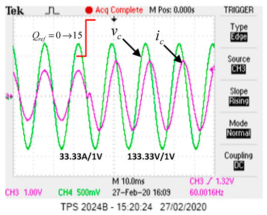
Figure 17.
Voltage and current for phase C during Pref = 10 kW and transition from Qref = 0 to Qref = 15 kVar.
4.1.2. Abnormal Conditions
The design system is subjected to various perturbations and non-ideal conditions, i.e., voltage sag, voltage swell, frequency variation, DC-link variation, inclusion of 5th harmonics during injection of active power, reactive power, both cases, etc. Figure 18 presents voltage and current for phase A during a drop in the grid voltage from 120 Vrms to 108 Vrms with Pref = 10 kW and Qref = 0 kVAr, clearly highlighted by arrows. A small transient is shown at the start, which is recovered abruptly. The response is faster and chatter-free. Figure 19 shows the voltage and current for phase A during an increase in the grid voltage from 108 Vrms to 120 Vrms with Pref = 10 kW and Qref = 0 kVAr. When the normal value of grid voltage has restored, the effect of the disturbance is negligible indicating the fault-tolerant behavior of ST-SMC. Figure 20 introduces voltage and current for phase A during f = 61 Hz, Pref = 10 kW, and Qref = 0 kVAr. The controller shows insensitivity to frequency variation. Figure 21 depicts voltage and current for phase A during the inclusion of oscillation in the DC-link voltage 38V at 120 Hz having Pref = 10 kW and Qref = 0. The DC-link variation has no effect on the current and voltage; the PLL works efficiently. The current and voltage are in phase and oscillation free. Figure 22 illustrates voltage and current for phase A during VDC = 380 V + 38 V at 120 Hz with Pref = 10 kW and Qref = 10 kVar. Due to the injection of reactive power, a phase shift is noticed in the current and voltage; moreover, there is no effect on the symmetry of waveforms validating the effectiveness of the design controller. Figure 23 portrays voltage and current for phase A during a swell in the grid voltage from 120 Vrms to 132 Vrms. A small transient shows the insertion of the swell point out with double-headed arrow. The voltage and current are in the phase where the waveform is distortion free. Figure 24 describes voltage and current for phase A during inclusion of 3% of 5th harmonic in the grid voltage with 120 Vrms, Pref = 10 k, and Qref = 0. Figure 25 demonstrates voltage and current for phase A during the inclusion of 3% of 5th harmonic in the grid voltage (120 Vrms and Pref = 10 k Qref = 10 kvar). The above two Figures show the behavior of the currents and voltages during the inclusion of 5th harmonics. The injected currents have high quality under harmonic distortions, thus authenticating that the design control is reliable, efficient, and less insensitive to abnormal conditions and uncertainties.
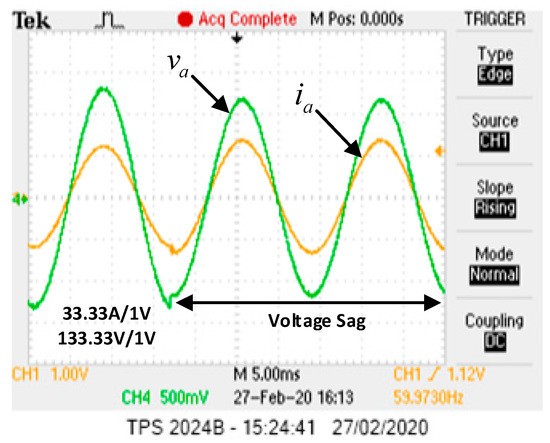
Figure 18.
Voltage and current for phase A during a drop in the grid voltage from 120 Vrms to 108 Vrms. Pref = 10 kW and Qref = 0 kVAr.
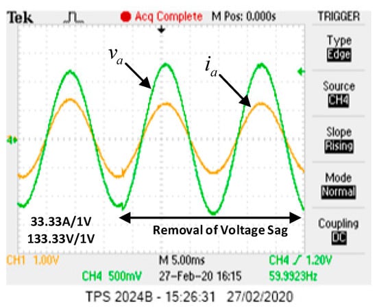
Figure 19.
Voltage and current for phase A during an increase in the grid voltage from 108 Vrms to 120 Vrms. Pref = 10 kW and Qref = 0 kVAr.
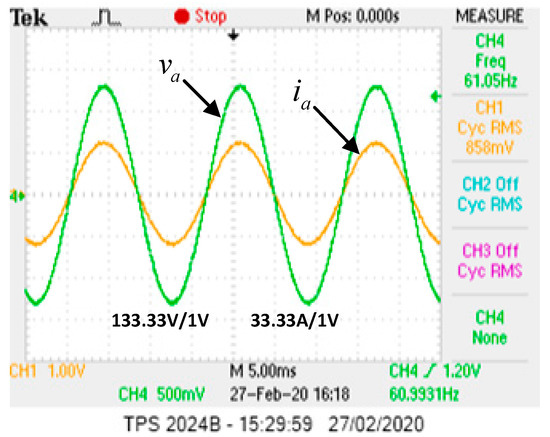
Figure 20.
Voltage and current for phase A during f = 61 Hz. Pref = 10 kW and Qref = 0 kVAr.
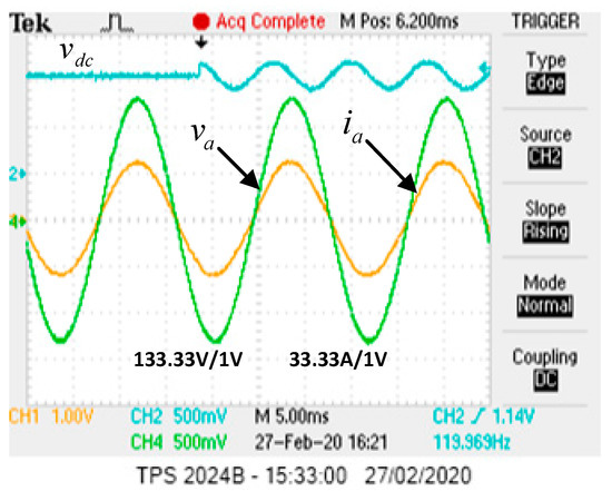
Figure 21.
Voltage and current for phase A during Vdc = 380 V + 38 V at 120 Hz. Pref = 10 kW and Qref = 0.
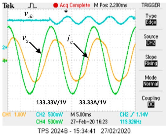
Figure 22.
Voltage and current for phase A during Vdc = 380 V + 38 V at 120 Hz. Pref = 10 kW and Qref = 10 kVar.
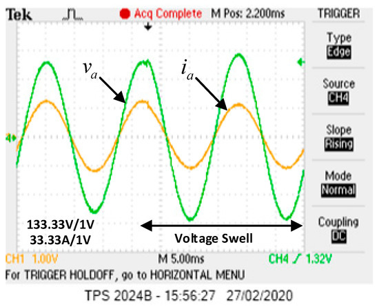
Figure 23.
Voltage and current for phase A during a swell in the grid voltage from 120 to 132 Vrms.
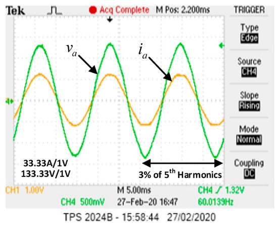
Figure 24.
Voltage and current for phase A during inclusion of 3% of the 5th harmonic in the grid voltage (120 Vrms and Pref = 10 k Qref = 0).
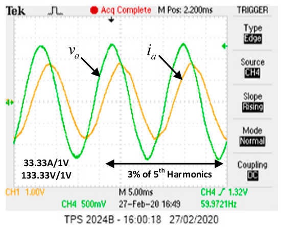
Figure 25.
Voltage and current for phase A during inclusion of 3% of 5th harmonic in the grid voltage (120 Vrms and Pref = 10 k Qref = 10 kvar).
5. Conclusions and Future Work
This paper successfully investigated the modeling and design of ST-SMC for efficiently injecting both active and reactive power under normal and abnormal operating conditions for a three-phase grid-connected PV system. The ST-SMC is analyzed and tested both under normal operation i.e., initialization, steady state behavior, dynamic behavior, and interrupting the injection of active and reactive power for normal operation as well as abnormal conditions, i.e., voltage sag, voltage swell, frequency variation, DC-link variation, inclusion of 5th harmonics, etc. The obtained finding shows that ST-SMC injects high-quality sinusoidal current with low THD, which is insensitive to a sudden disturbance, chatter-free, and fault-tolerant. The ST-SMC also ensures controllability, reliability, and safety for the interface with the utility grid. The HIL results authenticate the fastness, effectiveness, robustness, and stable operation for both steady-state and dynamic behavior of the designed controller.
In the near future, we will replace the simple inverter with a Modular Multilevel Inverter. Inserting an FRT strategy in compliance with modern grid code during symmetrical/asymmetrical faults and utilizing advance PLL is also one of direction. Moreover, a comparative assessment of advanced controller, i.e., H-infinity, Adaptive-SMC, Neuro-Fuzzy, etc., can also be performed. To further enhance the efficiency of the inverter, the silicon carbide (SiC) or gallium arsenide (GaN) devices will be used, instead of IGBT or MOSFET.
Author Contributions
K.Z.: Conceptualization, Methodology, Design, Software Results, and Writing—Original draft. T.D.C.B.: Typhoon HIL Results verification, Reviewing and Editing, and co-supervision. S.U.I.: Reviewing and Editing. W.U., K.V.G.R. and M.A.K.: Reviewing and Editing. H.-J.K.: Supervision, Financing, and Reviewing. All authors have read and agreed to the published version of the manuscript.
Funding
This work was supported by BK21PLUS, Creative Human Resource Development Program for IT Convergence.
Conflicts of Interest
The authors declare no conflict of interest.
References
- Zeb, K.; Uddin, W.; Khan, M.A.; Ali, Z.; Ali, M.U.; Christofides, N.; Kim, H.J. A Comprehensive Review on Inverter Topologies and Control Strategies for Grid Connected Photovoltaic System. Renew. Sustain. Energy Rev. 2018, 94, 1120–1141. [Google Scholar] [CrossRef]
- Yu, C.; Xu, H.; Liu, C.; Wang, Q.; Zhang, X. Modeling and Analysis of Common-Mode Resonance in Multi Parallel PV String Inverters. IEEE Trans. Energy Convers. 2019, 34, 446–454. [Google Scholar] [CrossRef]
- REN21. Renewables 2015: Global Status Report (GRS). 2015. Available online: http://www.ren21.net/ (accessed on 3 June 2020).
- Wind Energy and Solar|Installed GW Capacity-Global and by Country. Available online: http://www.fi-powerweb.com/Renewable-Energy.html (accessed on 2 October 2019).
- Solar Power Europe. Global Market Outlook for Solar Power 2015–2019. 2015. Available online: http://www.solarpowereurope.org/ (accessed on 20 March 2020).
- Venkatramanan, D.; John, V. Dynamic Modeling and Analysis of Buck Converter Based Solar PV Charge Controller for Improved MPPT Performance. Ind. Appl. IEEE Trans. 2019, 55, 6234–6246. [Google Scholar] [CrossRef]
- Koutroulis, E.; Yang, Y.; Blaabjerg, F. Co-Design of the PV Array and DC/AC Inverter for Maximizing the Energy Production in Grid Connected Applications. IEEE Trans. Energy Convers. 2019, 34, 509–519. [Google Scholar] [CrossRef]
- Ahmed, A.; Manoharan, M.S.; Park, J. An Efficient Single-Sourced Asymmetrical Cascaded Multilevel Inverter with Reduced Leakage Current Suitable for Single-Stage PV Systems. IEEE Trans. Energy Convers. 2019, 34, 211–220. [Google Scholar] [CrossRef]
- Zakzouk, N.E.; Elsaharty, M.A.; Abdelsalam, A.K.; Helal, A.A.; Williams, B.W. Improved performance low-cost incremental conductance PV MPPT technique. IET Renew. Power Gener. 2016, 10, 561–574. [Google Scholar] [CrossRef]
- Xiao, X.; Huang, X.; Kang, Q. A hill-climbing-method-based maximum-power-point-tracking strategy for direct-drive wave energy converters. IEEE Trans. Ind. Electron. 2016, 63, 257–267. [Google Scholar] [CrossRef]
- Raghavendra, K.V.G.; Zeb, K.; Muthusamy, A.; Krishna, T.N.V.; Kumar, S.V.S.V.P.; Kim, D.-H.; Kim, M.-S.; Cho, H.-G.; Kim, H.-J. A Comprehensive Review of DC–DC Converter Topologies and Modulation Strategies with Recent Advances in Solar Photovoltaic Systems. Electronics 2020, 9, 31. [Google Scholar] [CrossRef]
- Belhachat, F.; Larbes, C. Comprehensive review on global maximum power point tracking techniques for PV systems subjected to partial shading conditions. Sol. Energy 2019, 183, 476–500. [Google Scholar] [CrossRef]
- Danandeh, M. Comparative and comprehensive review of maximum power point tracking methods for PV cells. Renew. Sustain. Energy Rev. 2018, 82, 2743–2767. [Google Scholar] [CrossRef]
- Ahmad, R.; Murtaza, A.F.; Sher, H.A. Power tracking techniques for efficient operation of photovoltaic array in solar applications—A review. Renew. Sustain. Energy Rev. 2019, 101, 82–102. [Google Scholar] [CrossRef]
- Fang, J.; Li, H.; Tang, Y.; Blaabjerg, F. On the inertia of future more electronics power systems. IEEE J. Emerg. Sel. Top. Power Electron. 2019, 7, 2130–2146. [Google Scholar] [CrossRef]
- Islam, S.U.; Zeb, K.; Din, W.U.; Khan, I.; Ishfaq, M.; Hussain, A.; Busarello, T.D.C.; Kim, H.J. Design of Robust Fuzzy Logic Controller Based on the Levenberg Marquardt Algorithm and Fault Ride Trough Strategies for a Grid-Connected PV System. Electronics 2019, 8, 429. [Google Scholar] [CrossRef]
- Basso, T.S. IEEE 1547 and 2030 Standards for Distributed Energy Resources Interconnection and Interoperability with the Electricity Grid; Tech. Rep. NREL/TP5D00-63157; Nature Renewable Energy Lab.: Golden, CO, USA, 2014. [Google Scholar]
- Han, Y.; Luo, M.; Zhao, X.; Guerrero, J.; Xu, L. Comparative performance evaluation of orthogonal-signal-generators based single-phase PLL algorithms—A survey. IEEE Trans. Power Electron. 2016, 31, 3932–3944. [Google Scholar] [CrossRef]
- Kong, L.; Shi, Z.; Cai, G.; Liu, C.; Xiong, C. Phase-Locked Strategy of Photovoltaic Connected to Distribution Network With High Proportion Electric Arc Furnace. Access IEEE 2020, 8, 86012–86023. [Google Scholar] [CrossRef]
- Chowdhury, V.R.; Kimball, J.W. Control of a three-phase grid connected inverter under non-ideal grid conditions with online parameter update. IEEE Trans. Energy Convers. 2019, 34, 1613–1622. [Google Scholar] [CrossRef]
- Zeb, K.; Khan, I.; Uddin, W.; Khan, M.A.; Sathishkumar, P.; Busarello, T.D.C.; Ahmad, I.; Kim, H.J. A Review on Recent Advances and Future Trends of Transformerless Inverter Structures for Single-Phase Grid-Connected Photovoltaic Systems. Energies 2018, 11, 1968. [Google Scholar] [CrossRef]
- Uddin, W.; Zeb, K.; Tanoli, A.; Haider, A. Hardware-based hybrid scheme to improve the fault ride through capability of doubly fed induction generator under symmetrical and asymmetrical fault. IET Gener. Transm. Distrib. 2018, 12, 200–206. [Google Scholar] [CrossRef]
- Vahedi, H.; Labbe, P.-A.; Al-Haddad, K. Sensor-Less Five-Level Packed U-Cell (PUC5) Inverter Operating in Stand-Alone and Grid- Connected Modes. IEEE Trans. Ind. Inform. 2016, 12, 361–370. [Google Scholar] [CrossRef]
- Jafari, M.; Malekjamshidi, Z.; Zhu, J.; Khooban, M. Novel Predictive Fuzzy Logic-Based Energy Management System for Grid-connected and Off-grid Operation of Residential Smart Micro-grids. IEEE J. Emerg. Sel. Top. Power Electron. 2018, 8, 1391–1404. [Google Scholar] [CrossRef]
- Arora, A.; Singh, A. Design and implementation of Legendre-based neural network controller in grid-connected PV systems. IET Renew. Power Gener. 2019, 13, 2783–2792. [Google Scholar] [CrossRef]
- Sun, Y.; Li, S.; Lin, B.; Fu, X.; Ramezani, M.; Jaithwa, I. Artificial neural network for control and grid integration of residential solar photovoltaic systems. IEEE Trans. Sustain. Energy 2017, 8, 1484–1495. [Google Scholar] [CrossRef]
- Santra, S.B.; Kumar, K.; Biswal, P.; Panigrahi, C.K. Lyapunov Based Fast Terminal Sliding Mode QV Control of Grid Connected Hybrid Solar PV and Wind System. IEEE Access 2018, 6, 39139–39153. [Google Scholar] [CrossRef]
- Sebaaly, F.; Vahedi, H.; Kanaan, H.; Moubayed, N.; Al-Haddad, K. Design and Implementation of Space Vector Modulation Based Sliding Mode Control for Grid-Connected 3L-NPC Inverter. IEEE Trans. Ind. Electron. 2016, 63, 7854–7863. [Google Scholar] [CrossRef]
- Pahari, O.P.; Subudhi, B. Integral sliding mode-improved adaptive MPPT control scheme for suppressing grid current harmonics for PV system. IET Renew. Power Gener. 2018, 12, 1904–1914. [Google Scholar] [CrossRef]
- Zeb, K.; Islam, S.U.; Din, W.U.; Khan, I.; Ishfaq, M.; Busarello, T.D.C.; Ahmad, I.; Kim, H.J. Design of Fuzzy-PI and Fuzzy-Sliding Mode Controllers for Single-Phase Two-Stages Grid-Connected Transformerless Photovoltaic Inverter. Electronics 2019, 8, 520. [Google Scholar] [CrossRef]
- Yang, H.; Zhang, Y.; Liang, J.; Gao, J.; Walker, P.D.; Zhang, N. Sliding-Mode Observer Based Voltage-Sensorless Model Predictive Power Control of PWM Rectifier Under Unbalanced Grid Conditions. IEEE Trans. Ind. Electron. 2018, 65, 5550–5560. [Google Scholar] [CrossRef]
- Sajadian, S.; Ahmadi, R. Model Predictive Control of Dual-Mode Operations Z-Source Inverter: Islanded and Grid-Connected. IEEE Trans. Power Electron. 2018, 33, 4488–4497. [Google Scholar] [CrossRef]
- Errouissi, R.; Muyeen, S.; Al-Durra, A.; Leng, S. Experimental validation of a robust continuous nonlinear model predictive control-based grid-interlinked photovoltaic inverter. IEEE Trans. Power Electron. 2016, 63, 4495–4505. [Google Scholar] [CrossRef]
- Mohapatra, S.R.; Agarwal, V. Model Predictive Controller with Reduced Complexity for Grid Tied Multilevel Inverters. IEEE Trans. Power Electron. 2018, 66, 8851–8855. [Google Scholar] [CrossRef]
- Manoharan, M.S.; Ahmed, A.; Park, J. An Improved Model Predictive Controller for 27-level Asymmetric Cascaded Inverter Applicable in High Power PV Grid-Connected Systems. IEEE J. Emerg. Sel. Top. Power Electron. 2019. [Google Scholar] [CrossRef]
- Vu, P.; Nguyen, Q.; Tran, M.; Todeschini, G.; Santoso, S. Adaptive backstepping approach for dc side controllers of Z-source inverters in grid-tied PV system applications. IET Power Electron. 2018, 11, 2346–2354. [Google Scholar] [CrossRef]
- Liu, T.; Wang, D.; Zhou, K. High-performance grid simulator using parallel structure fractional repetitive control. IEEE Trans. Power Electron. 2016, 31, 2669–2679. [Google Scholar] [CrossRef]
- Xie, C.; Zhao, X.; Savaghebi, M.; Meng, L.; Guerrero, J.M.; Vasquez, J.C. Multirate fractional-order repetitive control of shunt active power filter suitable for microgrid applications. IEEE J. Emerg. Sel. Top. Power Electron. 2016, 5, 809–819. [Google Scholar] [CrossRef]
- Lidozzi, A.; Ji, C.; Solero, L.; Zanchetta, P.; Crescimbini, F. Resonant repetitive combined control for stand-alone power supply units. IEEE Trans. Ind. Appl. 2015, 51, 4653–4663. [Google Scholar] [CrossRef]
- Yang, Y.; Zhou, K.; Wang, H.; Blaabjerg, F. Analysis and Mitigation of Dead-Time Harmonics in the Single-Phase Full-Bridge PWM Converter With Repetitive Controllers. IEEE Trans. Ind. Appl. 2018, 54, 5343–5354. [Google Scholar] [CrossRef]
- Komurcugil, H.; Ozdemir, S.; Sefa, I.; Altin, N.; Kukrer, O. Sliding-Mode Control for Single-Phase Grid-Connected LCL-Filtered VSI With Double-Band Hysteresis Scheme. IEEE Trans. Ind. Electron. 2016, 63, 864–873. [Google Scholar] [CrossRef]
- Zhang, H.; Li, X.; Xiao, S.; Balog, R.S. Hybrid hysteresis current control and low-frequency current harmonics mitigation based on proportional resonant in dc/ac inverter. IET Power Electron. 2018, 13, 2093–2101. [Google Scholar] [CrossRef]
- Goh, H.; Armstrong, M.; Zahawi, B. Adaptive control technique for suppression of resonance in grid-connected PV inverters. IET Power Electron. 2019, 12, 1479–1486. [Google Scholar] [CrossRef]
- Sekhar, P.C.; Mishra, S.; Sharma, R. Data analytics based neuro-fuzzy controller for diesel-photovoltaic hybrid AC microgrid. IET Gener. Transm. Distrib. 2015, 9, 193–207. [Google Scholar] [CrossRef]
- Errouissi, R.; Al-Durra, A.; Muyeen, S.M. Offset-free feedback linearisation control of a three-phase grid-connected photovoltaic system. IET Power Electron. 2016, 9, 1933–1942. [Google Scholar] [CrossRef]
- Kuntanapreeda, S. Super-twisting sliding-mode traction control of vehicles with tractive force observer. Control Eng. Pract. 2015, 38, 26–36. [Google Scholar] [CrossRef]
- Mehta, A.; Naik, B. Sliding Mode Controllers for Power Electronic Converters; Springer: Berlin/Heidelberg, Germany, 2019. [Google Scholar]
- Msaddek, A.; Gaaloul, A.; M’Sahli, F. Comparative study of higher order sliding mode controllers. In Proceedings of the 2014 15th International Conference on Sciences and Techniques of Automatic Control and Computer Engineering (STA), Hammamet, Tunisia, 21–23 December 2014; pp. 915–922. [Google Scholar]
- Zheng, Y.; Liu, J.; Liu, X.; Fang, D.; Wu, L. Adaptive second-order sliding mode control design for a class of nonlinear systems with unknown input. Math. Probl. Eng. 2015, 2015. [Google Scholar] [CrossRef][Green Version]
- Guo, B.; Su, M.; Sun, Y.; Wang, H.; Dan, H.; Tang, Z.; Cheng, B. A robust second-order sliding mode control for single-phase photovoltaic grid-connected voltage source inverter. IEEE Access 2019, 7, 53202–53212. [Google Scholar] [CrossRef]
- Evangelista, C.A.; Pisano, A.; Puleston, P.; Usai, E. Receding Horizon Adaptive Second-Order Sliding Mode Control for Doubly-Fed Induction Generator Based Wind Turbine. IEEE Trans. Control Syst. Technol. 2017, 25, 73–84. [Google Scholar] [CrossRef]
- Jouini, M.; Dhahri, S.; Sellami, A. Design of robust supertwisting algorithm based second order sliding mode controller for nonlinear systems with both matched and unmatched uncertainty. Complexity 2017, 2017. [Google Scholar] [CrossRef]
- Lin, F.; Lu, K.; Ke, T.; Yang, B.; Chang, Y. Reactive Power Control of Three-Phase Grid-Connected PV System During Grid Faults Using Takagi–Sugeno–Kang Probabilistic Fuzzy Neural Network Control. IEEE Trans. Ind. Electron. 2015, 62, 5516–5528. [Google Scholar] [CrossRef]
- Teodorescu, R.; Liserre, M.; Rodriguez, P. Grid Converters for Photovoltaic and Wind Power Systems; Wiley: Hoboken, NJ, USA, 2011; pp. 219–221. [Google Scholar]
- Simoes, M.G.; Farret, F.A. Modeling Power Electronics and Interfacing Energy Conversion Systems; John Wiley & Sons: Hoboken, NJ, USA, 2017. [Google Scholar]
- Busarello, T.D.C.; Zeb, K.; Péres, A.; Oruganti, V.S.R.V.; Simões, M.G. Designing a Second Order Generalized Integrator Digital Phase Locked Loop based on a Frequency Response Approach. In Proceedings of the 2019 IEEE PES Innovative Smart Grid Technologies Conference—Latin America (ISGT Latin America), Gramado, Brazil, 15–18 September 2019; pp. 1–6. [Google Scholar]
- Chittora, P.; Singh, A.; Singh, M. Adaptive EPLL for improving power quality in three-phase three-wire grid-connected photovoltaic system. IET Renew. Power Gener. 2019, 13, 1595–1602. [Google Scholar] [CrossRef]
- Golestan, S.; Monfared, M.; Freijedo, F.D. Design-oriented study of advanced synchronous reference frame phase-locked loops. IEEE Trans. Power Electron. 2013, 28, 765–778. [Google Scholar] [CrossRef]
- Islam, S.U.; Zeb, K.; Din, W.U.; Khan, I.; Ishfaq, M.; Busarello, T.D.C.; Kim, H.J. Design of a Proportional Resonant Controller with Resonant Harmonic Compensator and Fault Ride Trough Strategies for a Grid-Connected Photovoltaic System. Electronics 2018, 7, 451. [Google Scholar] [CrossRef]
- Zhou, D.; Song, Y.; Blaabjerg, F. Modelling and Control of three-phase ac/dc converter including Phase Locked Loop. Control Power Electron. Convert. Syst. 2018, 1, 117–151. [Google Scholar]
- Armi, P.D. A quick introduction to sliding mode control and its applications. Univ. Degli Studi Di Cagliari 2016, 1–22. Available online: https://www.semanticscholar.org/paper/A-Quick-Introduction-to-Sliding-Mode-Control-and-1-DeCarlo-Zak/fa8b3d31508a983e3037fb82505a8b014ae1dc4d/ (accessed on 2 March 2020).
- Uddin, W.; Zeb, K.; Adil Khan, M.; Ishfaq, M.; Khan, I.; Islam, S.; Kim, H.-J.; Park, G.S.; Lee, C. Control of Output and Circulating Current of Modular Multilevel Converter Using a Sliding Mode Approach. Energies 2019, 12, 4084. [Google Scholar] [CrossRef]
- Levant, A. Sliding order and sliding accuracy in sliding mode control. Int. J. Control 1993, 58, 1247–1263. [Google Scholar] [CrossRef]
- Kunusch, C.; Puleston, P.; Mayosky, M. Sliding-Mode Control of PEM Fuel Cells; Springer: Berlin/Heidelberg, Germany, 2012. [Google Scholar]
- Bartolini, G.; Ferrara, A.; Levant, A.; Usai, E. On second order sliding mode controller” in Variable structure systems, sliding mode and nonlinear control. In Lecture Notes in Control and Information Sciences; Springer: Berlin/Heidelberg, Germany, 1999; Volume 247. [Google Scholar]
- Derbeli, M.; Barambones, O.; Ramos-Hernanz, J.A.; Sbita, L. Real-Time Implementation of a Super Twisting Algorithm for PEM Fuel Cell Power System. Energies 2019, 12, 1594. [Google Scholar] [CrossRef]
- Fridman, L.; Levant, A. Higher order sliding modes. In Sliding Mode Control in Engineering; Marcel Dekker Inc.: New York, NY, USA, 2002; pp. 53–101. [Google Scholar]
- Seeber, R.; Horn, M. Stability proof for a well-established supertwisting parameter setting. Automatica 2017, 84, 241–243. [Google Scholar] [CrossRef]
- Shtessel, Y.B.; Edwards, C.; Fridman, L.; Levant, A. Sliding Mode Control and Observation; Springer: New York, NY, USA, 2014. [Google Scholar] [CrossRef]
- Osório, C.R.D.; Koch, G.G.; Humberto, P.; Ricardo, C.L.F.O.; Montagner, V.F. Robust Current Control of Grid-Tied Inverters Affected by LCL Filter Soft-Saturation. IEEE Trans. Ind. Electron. 2019, 67, 6550–6561. [Google Scholar] [CrossRef]
- HIL402. Typhoon Inc. Available online: https://www.typhoon-hil.com/products/hil402/ (accessed on 2 February 2020).
© 2020 by the authors. Licensee MDPI, Basel, Switzerland. This article is an open access article distributed under the terms and conditions of the Creative Commons Attribution (CC BY) license (http://creativecommons.org/licenses/by/4.0/).