Article

Influence of Control and Structure Parameters on the Starting Performance of a 12/8 Pole Switched Reluctance Motor

School of Electrical and Electronic Engineering, Harbin University of Science and Technology, Harbin 150080, China
*
Author to whom correspondence should be addressed.
Energies 2020, 13(14), 3744; https://doi.org/10.3390/en13143744
Submission received: 14 March 2020 / Revised: 13 June 2020 / Accepted: 15 June 2020 / Published: 21 July 2020
(This article belongs to the Section E: Electric Vehicles)

Abstract

:
To investigate the influence of control and structure parameters on the starting performance of a switched reluctance motor, a 12/8 pole switched reluctance motor is analyzed in this paper. The novel field-circuit coupled finite element method of switched reluctance motor is proposed in the paper. The influence of the controller on the switched reluctance motor is considered. The influence of rotor initial position angle, starting mode, starting current, and structure parameters on the starting performance of the switched reluctance motor is studied using the field-circuit coupled finite element method. The starting performance of the switched reluctance motor is obtained under the different control and structure parameters. The alternating starting mode of single- and two-phase winding can improve the starting torque of switched reluctance motor (SRM). As the stator pole arc coefficient increases, the starting torque of SRM increases. The appropriate reduction of the air gap length can improve the starting torque of SRM. Experimental results of the prototype are compared with the calculation results, which verifies the reliability of the calculation method and accuracy of the calculation results.

1. Introduction

Switched reluctance motor has the advantages of simple structure, high reliability, small starting current, and high starting torque. They are suitable for many harsh environments or conditions. In recent years, they have been widely used in the aerospace, hybrid vehicles, and textiles.
Extensive studies are performed on the multi-physics field in the switched reluctance motor (SRM). Takeno et al. performed the test result and torque improvement of the 50 kW switched reluctance motor designed for hybrid electric vehicles [1]. Arbab et al. carried out the thermal modeling and analysis of a double-stator switched reluctance motor [2]. Ralllabandi et al. focused on the optimal design of a switched reluctance motor with magnetically disconnected rotor models, using a design of experiments differential evolution FEA-based method [3]. Fernández et al. focused on the experimental validation of a thermal model for high-speed switched reluctance machines for traction applications [4]. Oliveira et al. performed the finite element analysis simulation of switched reluctance motor drive [5]. Santos et al. researched the multiphysics NVH modeling: simulation of a switched reluctance motor for an electric vehicle [6]. Faiz et al. performed the temperature rise analysis of switched reluctance motors due to electromagnetic losses [7]. Cao et al. focused on the nonlinear modeling of electromagnetic forces for the planar-switched reluctance motor [8]. Some other experts also studied the multi-physics field of switched reluctance motor [9,10,11,12,13,14], but very few focused on the numerical relationship of the starting torque of the switched reluctance motor under the different control parameters and structure parameters.
Figure 1 shows the prototype of 12/8 pole SRM. Figure 2 shows the schematic of 12/8 pole SRM. For the 12/8 pole switched reluctance motor, A-phase excitation winding is aligned with the rotor teeth in Figure 2. If there is current in the B-phase excitation winding at the next moment, the rotor of SRM rotates counterclockwise. If there is current in the C-phase excitation winding at the next moment, the rotor of SRM rotates clockwise.
According to the characteristics of the crane motor, SRM is studied to replace the traditional three-phase induction motor. The prototype of SRM is designed and manufactured. The novelty of the work is as follows: (1) the novel field-circuit coupled finite element method of switched reluctance motor is proposed in the paper. The influence of the controller on the switched reluctance motor is considered. The influence of rotor initial position angle, starting mode, starting current, and structure parameters on the starting performance of the switched reluctance motor is studied using the field-circuit coupled finite element method. The corresponding change of starting torque of the switched reluctance motor is obtained. Experimental results of the prototype are compared with the calculation results, which verifies the reliability of the calculation method and accuracy of the calculation results. Since the calculation method in this paper is both correct and reliable, this calculation method can be generalized for application to all SRMs and provides an important reference for further narrowing the design choices. This novel calculation method can effectively overcome the challenges and difficulties faced by designers of SRMs and save a lot of research funding and scientific research time. (2) In this paper, the starting performance of switched reluctance motor is analyzed in detail under the different control parameters and structure parameters. The methods of improving the starting torque of SRM are given. These methods provide an important reference for the design of SRM, which can be generalized for application to all SRMs.

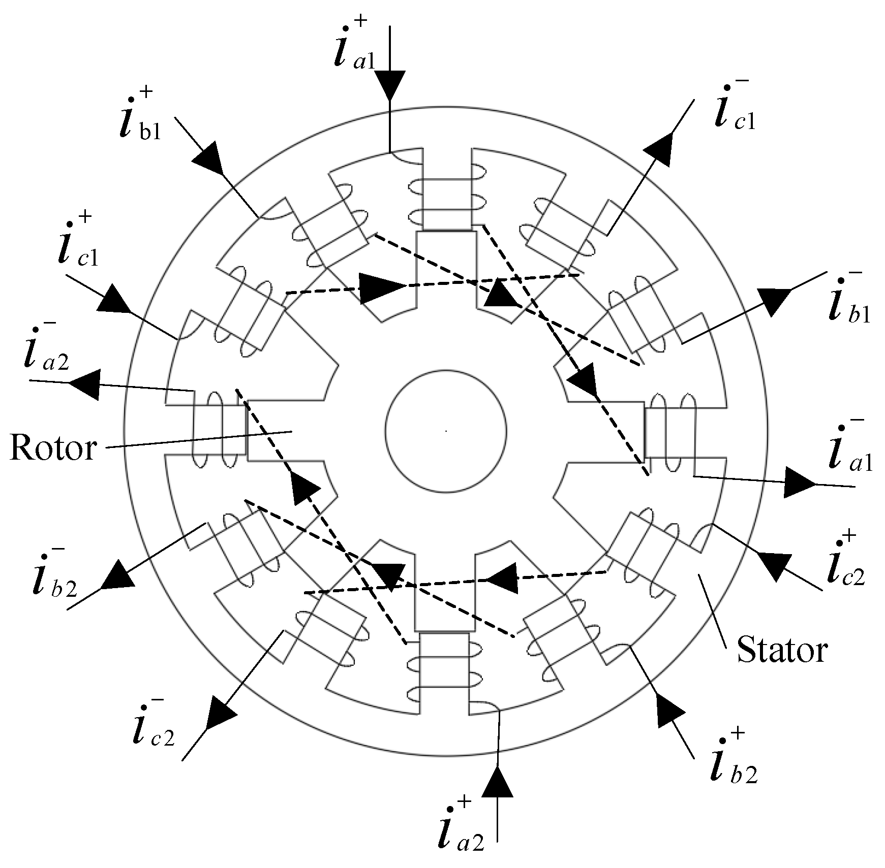
2. Establishment of SRM Field-Circuit Coupling Finite Element Model

Table 1 shows the basic parameters of the 5.5 kW, 12/8 pole switched reluctance motor.
In this paper, the starting performance of 12/8 pole switched reluctance motor is studied by the field-circuit coupled finite element method. The field-circuit coupled finite element model of the 12/8 pole switched reluctance motor is established, as shown in Figure 3. The field-circuit coupled finite element model includes mainly 12/8 pole SRM, three-phase rectifier, power converter, controller, and position sensor, etc. Double salient pole structure and concentrated winding are used in the SRM.
Figure 4 shows the meshing map and magnetic density distribution of SRM. Software ANSOFT is used. The total number of elements is 12,520. Mean element area is 1.80946 ×   1 0 7 m2. RMS (root mean square) edge length is 0.0013 m. It takes 6 h to complete the calculation each time. The computer has a random-access memory of 32 GB and a 3.60 GHz Intel® Core™ i7-3820 central processing unit.

3. Influence of Rotor Initial Position Angle on Starting Torque of SRM

The starting torque of the 12/8 pole SRM is calculated by the field-circuit coupled finite element method [15,16,17,18,19,20]. The starting torque of SRM means the blockage torque of SRM in this paper. The applied starting current is 22 A. The starting torque characteristic curve of SRM is given when the starting mode of one-phase winding is used, as shown in Figure 5. The results are not obtained from FEM (finite element method) in Figure 5.
In this paper, the rotor initial position angles are 0° (centerline between rotor poles coincides with stator tooth centerline and phase C is on), 3.75° (rotor rotates clockwise by 3.75° on the basis of 0°), and 12° (rotor rotates clockwise by 12° on the basis of 0° and phase A is on) are selected. The starting torque of SRM is calculated under the different rotor initial position angles. Figure 6 shows the position of the rotor when the rotor initial position angle is 0°. Figure 7 shows the starting torque of SRM under the different rotor initial position angles.
It can be seen from Figure 7 that the starting torque of the SRM is different when the rotor initial position angle is different. The starting torque of the SRM is 45.32 N·m when rotor initial position angle is 0°. The starting torque of the SRM is 24.69 N·m when rotor initial position angle is 3.75°. Starting torque of SRM when rotor initial position angle is 0° is 1.84 times that of SRM when rotor initial position angle is 3.75°. The starting torque of the SRM is 54.86 N·m when rotor initial position angle is 12°. Starting torque of SRM when rotor initial position angle is 12° is 2.22 times that of SRM when rotor initial position angle is 3.75°.

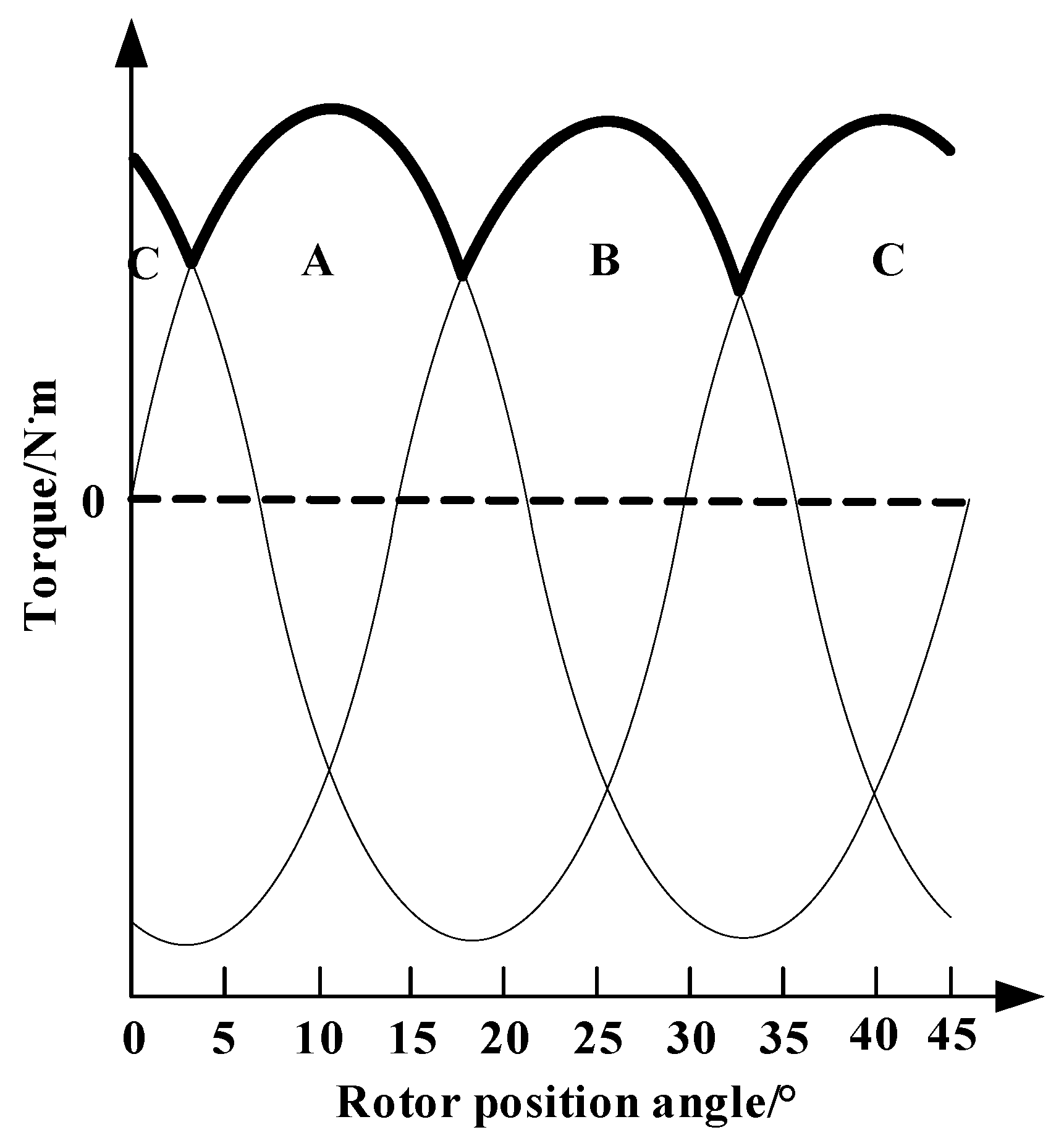
4. Influence of Starting Mode on Starting Torque of SRM

The rotor pole pitch angle of 12/8 pole SRM rotor is 45°. Starting mode of one-phase winding is a situation that there is the current in the only one stator winding and 1/3 rotor pole pitch angle continues for this phase winding. The conduction interval of phase A is 3.75°–18.75°. The conduction interval of phase B is 18.75°–33.75°. The conduction interval of phase C is 0°–3.75° and 33.75°–45°. Alternating the starting mode of single- and two-phase winding is a situation that CA-A-AB-B-BC-C stator windings are alternately fed with current in the rotor pole pitch angle of 12/8 pole SRM rotor. The torque characteristic is shown in Figure 8. The results are not obtained from FEM in Figure 8. The conduction interval of phase A is 0°–22.5°. The conduction interval of phase B is 15°–37.5°. The conduction interval of phase C is 0°–7.5° and 30°–45°. Comparing Figure 5 with Figure 8, it can be seen that the torque ripple is smaller when the alternating starting mode of single- and two-phase winding is used.
The electromagnetic torque expression of SRM is given,
T = x = 1 m T x ( θ , i )
T x ( θ , i ) = 0 i L ( θ , i ) i d i θ = 0 i ( L ( θ , i ) ) θ i d i ( x = 1 , 2 , 3 , )
where L ( θ , i ) is phase inductance. m is the phase number.
The rotor position angle θ i is 3.75°. The starting torque of SRM is obtained when both stator winding A and stator winding C are fed with current, as shown in Figure 9a. The starting torque of SRM is obtained when stator winding C is fed with current, as shown in Figure 9b.
The average starting torque of SRM is 34.23 N·m, when both stator winding A and stator winding C are fed with current. The average starting torque of SRM is 24.69 N·m when stator winding C is fed with current. The average starting torque of SRM when both stator winding A and stator winding C are fed with current is 1.39 times that of SRM when stator winding C is fed with current.
When the electromagnetic torque is generated in the 12/8 pole SRM, two stator windings can be fed with current at most. If the conduction angle is too big, brake torque will be generated. It is necessary to set reasonably the conduction angle in the SRM. Figure 10 shows the starting torque of SRM when the starting mode of one-phase winding and the alternating starting mode of single- and two-phase winding are used, respectively. The results are obtained from FEM in Figure 10. In Figure 10, starting mode I means starting mode of one-phase winding. Starting mode II means alternating the starting mode of single- and two-phase winding.
It can be seen from Figure 10 that the starting torque of SRM is different when the two kinds of starting modes are used. The maximum starting torques of SRM are basically the same when the starting mode of one-phase winding and the alternating starting mode of single- and two-phase winding are used, respectively. The minimum starting torque of SRM is 24.69 N·m when the starting mode of one-phase winding is used. The minimum starting torque of SRM is 34.23 N·m when the alternating starting mode of single- and two-phase winding is used. The minimum starting torque of SRM when starting mode of one-phase winding is used is 1.39 times that of SRM when the alternating starting mode of single- and two-phase winding is used. The average starting torques of SRM are 42.75 N·m and 45.58 N·m, when the starting mode of one-phase winding and the alternating starting mode of single- and two-phase winding are used, respectively. The average starting torque of SRM when the starting mode of one-phase winding is used is 1.07 times that of SRM when the alternating starting mode of single- and two-phase winding is used.
In order to further study the difference between the two starting modes, the concept of starting dead zone is proposed in this paper. The starting dead zone refers to the rotor position where SRM cannot start successfully. This is because the starting torque is smaller than the rated load. In Figure 10, it refers to the position below the starting boundary. The red dotted line means the rated load (starting boundary) in Figure 10. If the starting torque is bigger than the rated load, SRM can start successfully. The starting torque of SRM is different when the two starting modes are used. It can be seen from Figure 10 that the starting dead zone when the starting mode of one-phase winding is used is larger than that when the alternating starting mode of single- and two-phase winding is used. In order to start smoothly and quickly, it is recommended to choose the alternating starting mode of single- and two-phase winding. The alternating starting mode of single- and two-phase winding can improve the obviously starting torque of SRM. Therefore, alternating the starting mode of single- and two-phase winding is used in this prototype of SRM.

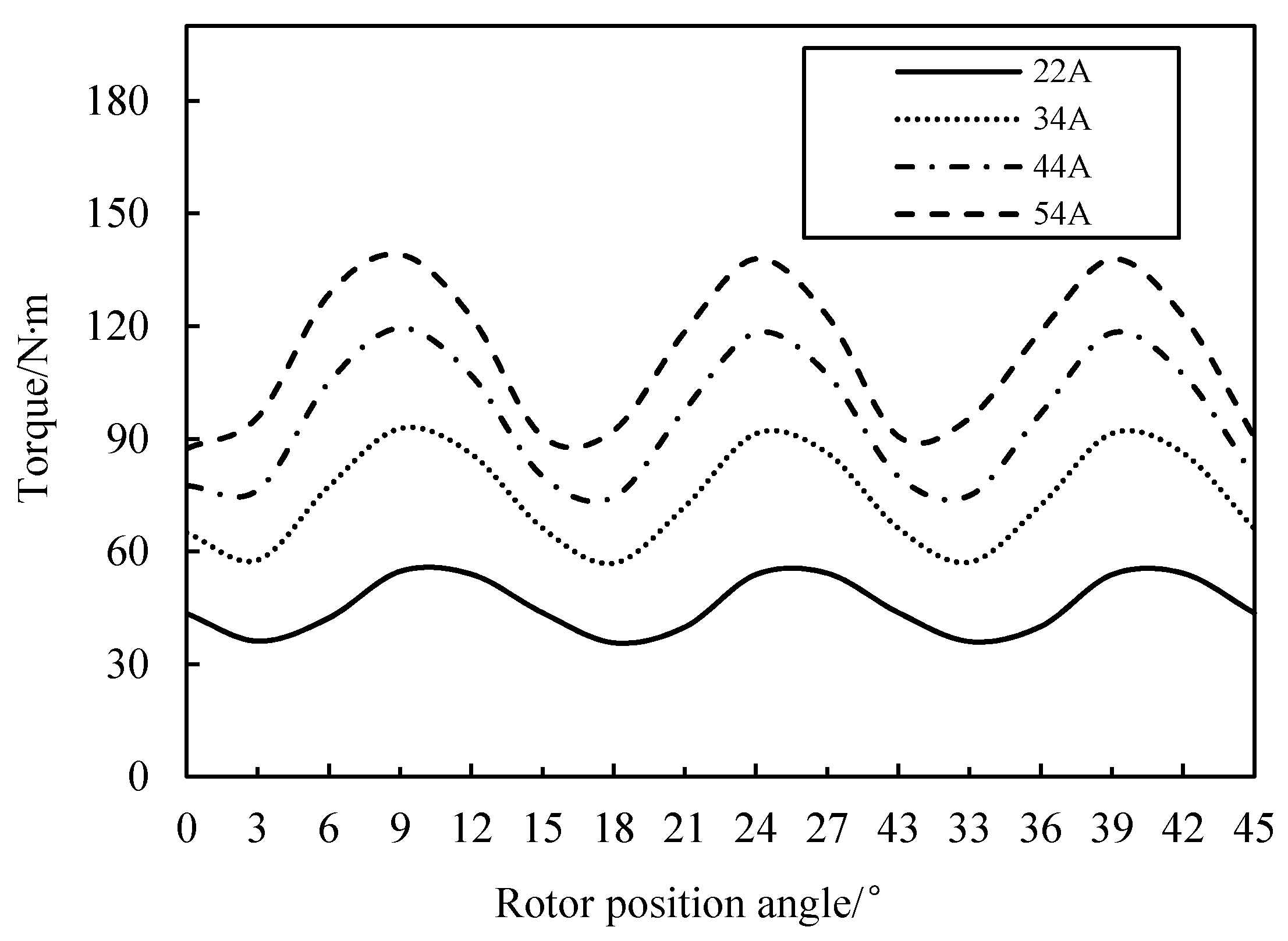
5. Influence of Starting Current on Starting Torque of SRM

Alternating starting mode of single- and two-phase winding is used. The starting torque of SRM is calculated when the starting current is 22 A, 34 A, 44 A, and 54 A, respectively, as shown in Figure 11. It can be seen from Figure 11 that starting torque increases with the increase of starting current under the same rotor position. The average starting torques of SRM are 112.02 N·m, 95.073 N·m, 74.5 N·m, and 45.58 N·m, when the starting currents are 54 A, 44 A, 34 A, and 22 A, respectively. The average starting torque of SRM when the starting current is 34 A is 1.63 times that of SRM when the starting current is 22 A. The average starting torque of SRM when the starting current is 54 A is 1.18 times that of SRM when the starting current is 44 A. The magnetic densities of the stator core teeth of SRM are different under the different starting currents. When the starting currents are 22 A, 34 A, 44 A, and 54 A, the average magnetic densities of the stator core teeth are 1.73 T, 1.82 T, 1.87, and 1.91 T, for the conducting phase winding, respectively. The average magnetic densities of the stator core teeth are 0.073 T, 0.12 T, 0.16 T, and 0.21 T for the non-conducting phase winding, respectively. Since the peak value of the rated current of SRM is 22 A, the peak value of the starting current is twice the peak value of rated current. The starting current is selected as 44 A. In addition, the starting torque exceeds twice the rated torque when the starting current is selected as 44 A. These meet the requirement of the crane motor.

6. Influence of Structure Parameters on Starting Torque of SRM

6.1. Influence of Stator and Rotor Pole arc Coefficient on Starting Torque of SRM

In order to study the influence of stator and rotor pole arc coefficient on the starting torque of SRM, different cases of stator and rotor pole arc coefficient are studied. Different cases of the stator and rotor pole arc coefficient are shown in Table 2.
Figure 12 shows the starting torque of SRM under the different stator and rotor pole arc coefficient. Figure 13 shows the average value and RMS value of starting torque under the different stator and rotor pole arc coefficient. Figure 14 shows the starting torque ripple coefficient under the different stator and rotor pole arc coefficient. The average starting torque of SRM is 43.12 N·m, 40.41 N·m, 41.31 N·m, 49.38 N·m, 50.32 N·m, 45.89 N·m, and 45.61 N·m when case I, case II, case III, case IV, case V, case VI and case VII are used, respectively. The starting torque ripple coefficient of SRM is 70.5%, 66.6%, 64.2%, 36.7%, 35.6%, 34.7%, and 38.7% when case I, case II, case III, case IV, case V, case VI and case VII are used, respectively. RMS value of starting torque is 44.53 N·m, 41.82 N·m, 42.72 N·m, 49.70 N·m, 50.86 N·m, 46.25 N·m, and 46.16 N·m when case I, case II, case III, case IV, case V, case VI and case VII are used, respectively. When the stator pole arc coefficient is constant, the starting torque ripple coefficient of the SRM decrease with the increase of rotor pole arc coefficient. When the rotor pole arc coefficient is constant, the starting torque ripple coefficient of the SRM decreases with the increase of stator pole arc coefficient. However, the average starting torque of the SRM increases with the increase of stator pole arc coefficient. In order to improve the starting torque of SRM, the rotor pole arc coefficient can be appropriately reduced and stator pole arc coefficient can be appropriately increased. The starting torque of SRM can be effectively improved when the stator pole arc coefficient is 0.49 and the rotor pole arc coefficient is 0.38. Case VII is used in this prototype of SRM.

6.2. Influence of Air Gap Length on Starting Torque of SRM

In order to study the influence of the air gap length on the starting torque of the SRM, the air gap length between the inner diameter of stator core and the top of the rotor salient pole tooth is selected as 0.2 mm, 0.3 mm, 0.4 mm, 0.5 mm, and 0.6 mm, respectively. Figure 15 shows the starting torque of SRM under the different air gap lengths.
It can be seen from Figure 15 that the average starting torque of SRM is 52.22 N·m, 48.81 N·m, 45.61 N·m, 42.52 N·m and 39.74 N·m when the air gap length between the inner diameter of stator core and the top of the rotor salient pole tooth is 0.2 mm, 0.3 mm, 0.4 mm, 0.5 mm, and 0.6 mm, respectively. The maximum starting torque of SRM is 64.29 N·m, 59.09 N·m, 54.73 N·m, 50.26 N·m, and 48.24 N·m when the air gap length between the inner diameter of stator core and the top of the rotor salient pole tooth is 0.2 mm, 0.3 mm, 0.4 mm, 0.5 mm, and 0.6 mm, respectively. The starting torque ripple coefficient of SRM is 47.4%, 44.2%, 41.7%, 36.8%, and 37.7%, when the air gap length between the inner diameter of stator core and the top of the rotor salient pole tooth is 0.2 mm, 0.3 mm, 0.4 mm, 0.5 mm, and 0.6 mm, respectively. The air gap length between the inner diameter of stator core and the top of the rotor salient pole tooth has an obvious effect on the starting torque of the SRM. The starting torque and the torque ripple coefficient of the SRM decrease with the increase of air gap length. The applied starting current is 22 A. When the air gap length between the inner diameter of stator core and the top of the rotor salient pole tooth is 0.2 mm, 0.3 mm, 0.4 mm, 0.5 mm, and 0.6 mm, the average magnetic densities of the stator core teeth are 1.76 T, 1.75 T, 1.73 T, 1.71 T, and 1.69 T for the conducting phase winding, respectively. The average magnetic densities of the stator core teeth are 0.084 T, 0.078 T, 0.073 T, 0.07 T, and 0.068 T for the non-conducting phase winding, respectively. The appropriate decrease of the air gap length between the inner diameter of stator core and the top of the rotor salient pole tooth can improve the starting torque of SRM. Based on the calculation result and actual craft process, the air gap length between the inner diameter of stator core and the top of the rotor salient pole tooth is selected as 0.4 mm in this prototype of SRM.

7. Establishment of the Static Electromagnetic Field Model of SRM

Figure 16 gives the static electromagnetic field model of SRM. The starting torque from the calculation of static electromagnetic field and starting torque from the calculation of transient field-circuit coupled finite element method are compared in detail at the different relative positions of the stator and rotor. The calculation results of starting torque are basically the same by the two kinds of calculation method. The difference of calculation results is within 1%, which verifies the reliability of the field-circuit coupled finite element method.

8. Comparison of Measured Values and Calculation Results

In order to verify the reliability of the calculation method and the accuracy of the calculation results, the test platform of 5.5 kW, 12/8 pole switched reluctance motor is shown in Figure 17. The test platform mainly includes SRM prototype, torque-speed measuring instrument, magnetic powder brake, wave recorder, and torque-speed indicator. Figure 18 shows the stator and rotor of 12/8 pole SRM. This SRM is a prototype.
Figure 19 shows the measured voltage waveform and current waveform of prototype under the rated operating condition. The peak value of the stator winding phase current is 22 A by the measurement. The peak value of the stator winding phase current is 22.96 A by the calculation. The measured value agrees well with the calculated result.
In order to verify the accuracy of the calculation results of the SRM starting torque, the measured values and the calculated results of the starting torque are compared when the starting current is 44 A in Figure 20. The rotor of SRM was blocked in the process of experiment. The rotor position angle was adjusted from 0° to 45°. The starting torque was measured at the different rotor position angles. The experimental results of the prototype are compared with the calculation results, which verifies the reliability of the calculation method and accuracy of the calculation results. Alternating the starting mode of single- and two-phase winding is used in the experiment. When the starting current is 44 A, the calculated average starting torque is 94.81 N·m and the measured average starting torque is 95.07 N·m. It shows that this calculation method is reliable and the calculation results are accurate.

9. Conclusions

In this paper, the influence of rotor initial position angle, starting mode, starting current, and structure parameters on the starting performance of the switched reluctance motor is studied. The reliability of the calculation method is verified by experimental results. The main conclusions are as follows.
(1).
The rotor initial position angle has an obvious effect on the starting torque of the SRM. The starting torques of the SRM are 45.32 N·m, 24.69 N·m, and 54.86 N·m when rotor initial position angle is 0°, 3.75°, and 12°, respectively. The maximum starting torques of SRM are basically the same when the starting mode of one-phase winding and the alternating starting mode of single- and two-phase winding are used, respectively.
(2).
Starting torque increases with the increase of starting current under the same rotor position. The average starting torques of SRM are 112.02 N·m, 95.073 N·m, 74.5 N·m, and 45.58 N·m, when the starting currents are 54 A, 44 A, 34 A, and 22 A, respectively. The average starting torque of SRM when the starting current is 34 A is 1.63 times that of SRM when the starting current is 22 A.
(3).
When the stator pole arc coefficient is constant, the starting torque ripple coefficient of the SRM decreases with the increase of the rotor pole arc coefficient. When the rotor pole arc coefficient is constant, the starting torque ripple coefficient of the SRM decreases with the increase of stator pole arc coefficient. However, the average starting torque of the SRM increases with the increase of the stator pole arc coefficient. The air gap length between the inner diameter of stator core and the top of the rotor salient pole tooth has an obvious effect on the starting torque of the SRM. The starting torque and the torque ripple coefficient of the SRM decreases with the increase of air gap length.

Author Contributions

J.H. provided the conceptualization and wrote the paper; J.G. provided the methodology; K.Z. implemented the simulation; Y.W. analyzed the data; C.W. checked the paper format. All authors have read and agreed to the published version of the manuscript.

Funding

This research was funded in part by the Heilongjiang Science and Technology Achievement Conversion and Cultivation Project under Grant TSTAU-R2018004, in part by the National Natural Science Foundation of China under Grant 51807043, in part by the Postdoctoral Foundation of Heilongjiang Province of China under Grant LBH-TZ1005, in part by the Fundamental Research Foundation for Universities of Heilongjiang Province under Grant 2019-KYYWF-0209, in part by the China Postdoctoral Science Foundation under Grant 2018T110269, in part by the China Postdoctoral Science Foundation under Grant 2018M630336, in part by the Fundamental Research Foundation for Universities of Heilongjiang Province under Grant 2018-KYYWF-1629, in part by the University Nursing Program for Young Scholars with Creative Talents in Heilongjiang Province under Grant UNPYSCT-2017080, and in part by the Postdoctoral Foundation of Heilongjiang Province of China under Grant LBH-Z17040.

Conflicts of Interest

The authors declare no conflict of interest.

Nomenclature

SRMSwitched reluctance motor
RMSRoot mean square
T Torque (N·m)
m Phase number
θ Rotor position angle ( ° )
i Phase current (A)
L ( θ , i ) Phase inductance (H)
i a A-phase current (A)
i b B-phase current (A)
i c C-phase current (A)

References

  1. Takeno, M.; Chiba, A.; Hoshi, N.; Ogasawara, S.; Takemoto, M.; Rahman, M.A. Test result and torque improvement of the 50-kW switched reluctance motor designed for hybrid electric vehicles. IEEE Trans. Ind. Appl. 2012, 48, 1327–1334. [Google Scholar] [CrossRef]
  2. Arbab, N.; Wang, W.; Lin, C.; Hearron, J.; Fahimi, B. Thermal modeling and analysis of a double-stator switched reluctance motor. IEEE Trans. Energy Convers. 2015, 30, 1209–1217. [Google Scholar] [CrossRef]
  3. Ralllabandi, V.; Wu, J.; Zhou, P.; Dorrel, D.G.; Ionel, D.M. Optimal design of a switched reluctance motor with magnetically disconnected rotor models using a design of experiments differential evolution FEA-based method. IEEE Trans. Magn. 2018, 54, 8205705. [Google Scholar] [CrossRef]
  4. Fernández, F.J.M.; Potgieter, J.H.J.; Fraser, A.G.; McCulloch, M.D. Experimental validation of a thermal model for high-speed switched reluctance machines for traction applications. IEEE Trans. Ind. Appl. 2018, 54, 3235–3244. [Google Scholar] [CrossRef]
  5. Oliveira, A.L.; Pelizari, A.; Filho, A.J.S. Finite element analysis simulation of switched reluctance motor drive. IEEE Lat. Am. Trans. 2018, 16, 1928–1933. [Google Scholar] [CrossRef]
  6. Santos, F.L.M.d.; Anthonisc, J.; Naclerio, F.; Gyselinck, J.J.C.; der Auweraer, H.V.; Goes, L.C.S. Multiphysics NVH modeling: Simulation of a switched reluctance motor for an electric vehicle. IEEE Trans. Ind. Electron. 2014, 61, 469–476. [Google Scholar] [CrossRef]
  7. Faiz, J.; Ganji, B.; Carstensen, C.E.; Kasper, K.A.; Doncker, R.W.D. Temperature rise analysis of switched reluctance motors due to electromagnetic losses. IEEE Trans. Magn. 2009, 45, 2927–2934. [Google Scholar] [CrossRef]
  8. Cao, G.; Li, L.; Huang, S.; Li, L.; Qian, Q.; Duan, J. Nonlinear modeling of electromagnetic forces for the planar-switched reluctance motor. IEEE Trans. Magn. 2015, 51, 8206605. [Google Scholar] [CrossRef]
  9. Pan, J.F.; Zou, Y.; Cao, G.; Cheung, N.C.; Zhang, B. High precision dual-loop position control of an asymmetric bilateral linear hybrid switched reluctance motor. IEEE Trans. Magn. 2015, 51, 1–5. [Google Scholar] [CrossRef]
  10. Ling, X.; Li, B.; Gong, L.; Huang, Y.; Liu, C. Simulation of switched reluctance motor drive system based on multi-physics modeling method. IEEE Access 2017, 5, 26184–26189. [Google Scholar] [CrossRef]
  11. Amoros, J.G.; Andrada, P.; Blanque, B.; Genesca, M.M. Influence of design parameters in the Optimization of linear switched reluctance motor under thermal constraints. IEEE Trans. Ind. Electron. 2018, 65, 1875–1883. [Google Scholar] [CrossRef] [Green Version]
  12. Liu, A.; Lou, J.; Yu, S. Influence of exciting field on electromagnetic torque of novel switched reluctance motor. IEEE Trans. Magn. 2019, 55, 8202807. [Google Scholar] [CrossRef]
  13. Toda, H.; Senda, K.; Morimoto, S.; Hiratani, T. Influence on various Non-oriented electrical steels on motor efficiency and iron loss in switched reluctance motor. IEEE Trans. Magn. 2013, 49, 3850–3853. [Google Scholar] [CrossRef]
  14. Afjei, E.; Siadatan, A.; Torkaman, H. Magnetic modeling, prototyping, and comparative study of a quintuple-set switched reluctance motor. IEEE Trans. Magn. 2015, 51, 8203407. [Google Scholar] [CrossRef]
  15. Sanches, E.S.; Santisteban, J.A. Mutual inductance effect on the torque of an axial magnetic flux switched reluctance motor. IEEE Lat. Am. Trans. 2015, 13, 2239–2244. [Google Scholar] [CrossRef]
  16. Han, J.; Ge, B.; Li, W. Influence of magnetic permeability of the press plate on the loss and temperature of the end part in the end region of a turbogenerator. IEEE Trans. Ind. Electron. 2019, 66, 162–171. [Google Scholar] [CrossRef]
  17. Cebolla, F.J.P.; Iturbe, A.M.; del Brio, B.M.; Bernal, C.; Neuz, A.B. Nonlinear lumped-circuit model for switched reluctance motors exhibiting core losses. IEEE Trans. Ind. Electron. 2016, 63, 3433–3445. [Google Scholar] [CrossRef]
  18. Bostanci, E.; Moallem, M.; Parsapour, A.; Fahimi, B. Opportunities and challenges of switched reluctance motor drives for electric propulsion: A comparative study. IEEE Transp. Electrif. 2017, 3, 58–75. [Google Scholar] [CrossRef]
  19. Xu, Y.; Chen, H.; Gu, J. Power loss analysis on switched reluctance motor converter by using electrothermal model. IET Power Electron. 2015, 8, 130–141. [Google Scholar] [CrossRef]
  20. Madhavan, R.; Fernandes, B.G. Performance improvement in the axial flux-segmented rotor-switched reluctance motor. IEEE Trans. Power Convers. 2014, 29, 641–651. [Google Scholar] [CrossRef]
Figure 1. According to the characteristics of the crane motor, prototype of 12/8 pole switched reluctance motor (SRM) is designed and manufactured.
Energies 13 03744 g001
Figure 2. Schematic of 12/8 pole SRM is shown. A-phase excitation winding is aligned with the rotor teeth.
Energies 13 03744 g002
Figure 3. Field-circuit coupled finite element model of 12/8 pole switched reluctance motor is shown. The starting performance of 12/8 pole switched reluctance motor is studied by the field-circuit coupled finite element method.
Energies 13 03744 g003
Figure 4. Meshing map and magnetic density distribution of SRM are shown. The total number of elements is 12,520.
Energies 13 03744 g004
Figure 5. Starting torque characteristic curve of SRM is shown when the starting mode of one-phase winding is used. The results are not obtained from FEM (finite element method).
Energies 13 03744 g005
Figure 6. Position of the rotor is shown. Centerline between rotor poles coincides with stator tooth centerline when the rotor initial position angle is 0°.
Energies 13 03744 g006
Figure 7. Starting torque of SRM is shown when rotor initial position angle is 0°, 3.75° and 12°, respectively.
Energies 13 03744 g007
Figure 8. Starting torque characteristic curve of SRM is shown when the alternating starting mode of single- and two-phase winding is used. The results are not obtained from FEM.
Energies 13 03744 g008
Figure 9. Starting torque of SRM is shown when different stator windings are fed with current.
Energies 13 03744 g009
Figure 10. Starting torque of SRM is shown under the different starting modes. The results are obtained from FEM.
Energies 13 03744 g010
Figure 11. Starting torque of SRM is shown when the starting current is 22 A, 34 A, 44 A, and 54 A, respectively.
Energies 13 03744 g011
Figure 12. Starting torque of SRM is shown under the different stator and rotor pole arc coefficient.
Energies 13 03744 g012
Figure 13. Average value and RMS (root mean square) value of starting torque of SRM are shown under the different stator and rotor pole arc coefficient.
Energies 13 03744 g013
Figure 14. Starting torque ripple coefficient of SRM is shown under the different stator and rotor pole arc coefficient.
Energies 13 03744 g014
Figure 15. Starting torque of SRM is shown when the air gap length between the inner diameter of stator core and the top of the rotor salient pole tooth is 0.2 mm, 0.3 mm, 0.4 mm, 0.5 mm, and 0.6 mm, respectively.
Energies 13 03744 g015
Figure 16. Static electromagnetic field model is established to study the starting torque of SRM.
Energies 13 03744 g016
Figure 17. Test platform of 12/8 pole SRM is established, to verify the reliability of the calculation method and the accuracy of the calculation results.
Energies 13 03744 g017
Figure 18. Stator and rotor of 12/8 pole SRM is shown. This SRM is a prototype.
Energies 13 03744 g018
Figure 19. Voltage waveform and current waveform of prototype are measured to verify the calculated result. Curve A is the voltage waveform (250 V/grid) and curve C is the current waveform (20 A/grid).
Energies 13 03744 g019
Figure 20. Measured values and calculated results of starting torque of SRM are compared when the starting current is 44 A.
Energies 13 03744 g020
Table 1. Basic parameters of 5.5 kW, 12/8 pole switched reluctance motor are shown.
ParametersValues
Rated power (kW)5.5
Rated speed (r/min)1500
Stator outer diameter (mm)210.7
Stator inner diameter (mm)116
Rotor outer diameter (mm)115.2
Rotor inner diameter (mm)57.6
Air gap (mm)0.4
Core length (mm)130.8
Coil turns per pole131
Material of stator and rotor coreDW310
Material of coilCopper
Table 2. Different cases are selected to study the influence of stator and rotor pole arc coefficient on the starting torque of SRM.
Case ICase IICase IIICase IVCase VCase VICase VII
Stator pole arc coefficient0.450.450.450.550.550.550.49
Rotor pole arc coefficient0.350.40.450.350.40.450.38

