Abstract
Since pneumatic systems are widely used in various branches of industry, the need to find ways to reduce energy consumption in these systems has become very pressing. The reduction in energy consumption in these systems is reflected in the reduction of compressed air consumption. The paper presents a cylinder control system with a piston rod on one side, in which the reduction in energy consumption is ensured by using different levels of supply pressure in the working and the return stroke, and by holding the cylinder piston rod in its final positions with a clamping cartridge. Clamping and holding the piston rod in its final position further affects the reduction in energy consumption. Experimental data show that the application of the proposed control leads to a decrease in compressed air consumption of 25.54% to 32.97%, depending on the compressed air pressure used in the return stroke. The cost-effectiveness of the proposed cylinder control with different levels of compressed air pressure and holding the final position by clamping cartridge is presented.
1. Introduction
Together with pneumatic actuators, pneumatic systems are widely used in numerous industrial applications. These systems use compressed air in their operation, such air being usually produced by electrical energy that drives a compressor. The electricity costs for compressed air production can constitute up to 20% of the entire electricity costs in an industry [1]. This is one of the most important reasons behind the search for ways to save energy when using pneumatic systems.
Numerous authors have dealt with the problem of energy efficiency of pneumatic systems and especially reduction of compressed air consumption. Al-Dakkan et al. [2] presented a method of energy saving in the context of a servo-controlled pneumatic actuator. Yang et al. [3,4] proposed a new booster valve with energy recovery for improving the energy efficiency of a pneumatic actuator system. Luciano et al. [5] introduced an alternative scheme with a fast switching on/off valve interconnecting the cylinder chambers, for reducing the consumption of compressed air in pneumatic positioning systems with external loads. Joshua et al. [6] introduced a pneumatic strain energy accumulator for recycling exhaust air from one pneumatic component, storing it in a highly efficient process and reusing the stored exhaust air at a constant pressure to power another pneumatic component. Wang et al. [7] used exergy-related analysis for evaluating the efficiency of pneumatic systems. Shen et al. [8] and Yang et al. [9] proposed an energy saving approach by supplementing a standard spool valve-controlled pneumatic actuator with an additional two-way valve that enables flow between the cylinder chambers. Seslija et al. [10] introduced the application of pulse-width modulation and by-pass chamber control of the pneumatic rodless cylinder. Bartyś et al. [11] proposed three practical measures of electro-pneumatic control quality, namely: variability, mean time, and cumulative effort. These measures are very useful in enabling optimization of positioner controller settings with respect to the controller effort and improving the energy efficiency of pneumatic systems. Kanno et al. [12] developed a three-port poppet-type servo valve to reduce air leakage and to improve the energy efficiency of the whole pneumatic system. Many authors wereimproving the energy efficiency in the driven actuator and making the circuit more complex, such as using dual pressure supply, utilizing expansion energy [13], recovering energy with a rubber bladder and storing the strain energy [14], or reusing exhaust air for power generation [15]. In addition, reusing exhaust air as input to the drive chamber of the cylinder led to velocity fluctuations [16]. Nehler T. [17] reviewed the existing base of scientific knowledge on energy efficiency in compressed air systems and suggested that energy efficiency measures in compressed air systems and related non-energy benefits should be studied on a specific measure level to fully understand and acknowledge their effects on the energy use of a compressed air system and possible additional effects, i.e., non-energy benefits.
All of the previous papers dealt with the problem of increasing the energy efficiency of pneumatic systems in various ways. Some of them proposed new booster valves [3,4]. Others reused exhaust air from one pneumatic component to the same component [5,8,9,10,15,16] or another component [6,15]. There were papers that proposed a new algorithm of control [2], optimization of positioner controller settings [11], and reducing air leakage to improve the energy efficiency of the whole pneumatic system [12].
This paper deals with the problem of decreasing compressed air consumption in executive pneumatic systems in a new way. The goal of this paper is to develop a new pneumatic system that uses various levels of compressed air in the working and the return cylinder stroke as well as keeps the cylinder piston rod at rest in final positions by a clamping cartridge, during which the supply to the cylinder chambers is cut off. The proposed pneumatic system, with various levels of compressed air supply and clamping cartridge, enables the reduction of compressed air consumption and at the same time an increase in the energy efficiency of the whole pneumatic system. If a lower compressed air pressure is used to supply the cylinder chambers, the compressed air consumption will be reduced. The proposed cylinder control system is presented in Section 2. In addition to the fact that using lower compressed air in the return cylinder stroke enables the reduction of compressed air consumption, it also leads to a decrease in the velocity of cylinder piston movement, which is explained and discussed in Section 3 and Section 4. In Section 4.1, the cost-effectiveness of the proposed system is discussed.
2. Cylinder Control System with Different Levels of Compressed Air Pressure and Holding the Final Position by Clamping Cartridge
The most often used executive part in conventional pneumatic systems comprises various double-acting pneumatic cylinders and a supply valve, and the same level of compressed air pressure Ps is used both in the working and in the return stroke of the cylinder. Figure 1 shows a typical pneumatic executive system with an actuator in the form of a double-acting cylinder with a piston rod on one side marked 1.0, and a 5/2-way monostable valve with electrical activation signal y marked 1.1.
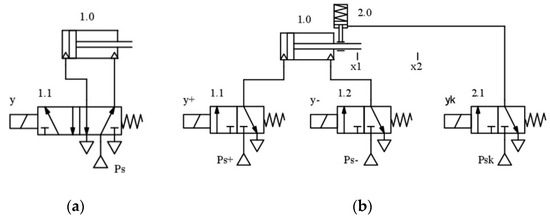
Figure 1.
A pneumatic executive system: (a) typical; (b) with different levels of compressed air pressure and holding the cylinder piston rod in its final position.
A pneumatic executive control system with different levels of compressed air pressure and holding the final position (Figure 1b) enables a reduction in compressed air consumption.
In the return stroke of the cylinder, it is possible to carry out the process using a lower level of air pressure and reduce consumption of compressed air. A pneumatic executive system that enables the use of different levels of compressed air pressure in the working and the return stroke of the cylinder requires the substitution of a common supply valve with two valves that allow for an independent supply of different levels of compressed air pressure to the cylinder chambers. In the present case, this is done by substituting a 5/2-way valve marked 1.1 in Figure 1a with two 3/2-way valves marked 1.1 and 1.2 in Figure 1b. The y+ and y- signals are the signals of the activation of valves 1.1 and 1.2, respectively, which serve to supply the cylinder chambers with an appropriate compressed air pressure. The simultaneous activation of y+ and y- signals is forbidden and it is called “prohibited state”. In Figure 1b, when the cylinder piston moves right, which represents the working stroke, valve 1.1 is activated and supplies the left cylinder chamber with a higher-pressure Ps+. In the return stroke, valve 1.2 is activated and the return stroke is performed, i.e., the cylinder piston moves to the left at a lower pressure Ps−. It is a well-known fact that as a cylinder moves, the level of pressure in its chamber falls below the level of supply, and the pressure rises to the maximum only at the end of the stroke, when the cylinder reaches its final position. This fact can be used to further reduce compressed air consumption by stopping the cylinder chamber’s supply at the end of the stroke and keeping the cylinder in its final position. This will prevent the rise of pressure in the cylinder chambers to its maximum. To do this, it is necessary to add cylinder clamping cartridges to the pneumatic executive system. The clamping cartridge 2.0 is executed in such a way that it releases the cylinder 1.0 only when compressed air is supplied to it, Figure 1b. To supply this clamping cartridge, the 3/2-way valve marked 2.1 is used, Figure 1b. The level of compressed air Psk for the supply of the clamping cartridge is equal to the level of the pressure necessary for the working stroke of the Ps+ cylinder. This is done to ensure that the cylinder is kept in its final position in a proper and safe manner. The detection of final positions of the cylinder is enabled by the limited sensors x1 for the drawn-in and x2 for the drawn-out position. In the working stroke, the cylinder is supplied with the Ps+ pressure, while the lower Ps− pressure is used in the return stroke.
A Mathematical Model of Cylinder Control with Different Levels of Compressed Air Pressure and Holding the Final Position by Clamping Cartridge
The mathematical model of the cylinder control system with different levels of compressed air pressure and holding the final position consists of the dynamic model of the cylinder, the model of pressure change in the cylinder chambers, and the model of flow change in the supply valve.
The dynamic model of the cylinder is Equation (1),
where ML is the mass of the external parts connected to the cylinder, MP the mass of the cylinder piston and the piston rod, x the position of the piston, β the coefficient of viscous friction, Ff the Coulomb friction force, FL the external force, P1 and P2 the absolute pressures in the cylinder chambers with their maximums being Ps+ or Ps−, depending on the level of compressed air used to supply the cylinder chambers, and A1 and A2 the effective surface areas of the piston and the piston rod chamber of the cylinder.
The righthand side of Equation (1) represents the cylinder active force, produced by the pressure differential acting across the cylinder piston. The existence of this force results in the displacement of the cylinder piston and the piston rod to the one or the other side. This active force directly influences the velocity of cylinder piston movement. If the lower compressed air pressure is used to supply the cylinder chambers, the active force will be lower, and the cylinder piston movement will be slower.
The equation that describes the model of the pressure change in the pneumatic cylinder chambers is Equation (2),
where R is the ideal gas constant, T the temperature, and the intake and exhaust mass flows from the cylinder chamber, respectively, V0i the inactive cylinder volumes, L the cylinder stroke length, and α αin, αout, the thermal coefficients. For the process of filling the chambers with compressed air, αin = κ = 1.4, while αout = 1 for the emptying process [17]. The thermal characteristics of the processes taking place while the piston is moving are better described if one understands that α = 1.2 [17]. Due to simplicity, the heat transfer losses have not been considered for the calculation of the gas temperature.
Because of simplicity, it is assumed that the length of the lines between the cylinder and the 3/2-way supply valves is not long, so that the intake and exhaust mass flows from the cylinder chambers depend only on the flow through the valve openings, as presented in Equation (3),
where cf is the non-dimensional emptying coefficient, and Pu and Pd the upstream and the downstream pressure, respectively. The value Av represents the surface area of the 3/2-way supply valve opening, and it can have the value of Av = Avsgn(Uv), where Uv is the voltage of the 3/2-way valve activation.
The values C1, C2 and Pcr, in Equation (3), are constants that depend on the fluid, in this case air (κ = 1.4) [17],
The unit that holds the cylinder in its final position also consumes a certain amount of compressed air. Since it represents a single-acting cylinder with a spring-operated return stroke (Figure 1b), the stroke and the dimensions of its work chamber are small; thus, the air consumption is not significant, because the chamber is supplied with the appropriate amount of compressed air very quickly, releasing the cylinder. The volume of the by clamping cartridge work chamber is much smaller than the volumes of the work chambers of the cylinder itself. The cylinder is held again by simply cutting off the supply of the by clamping cartridge.
Equation (3) shows that the mass flow of compressed air and its consumption are influenced, among other things, by the upper pressure Pu that can be maximally equal to Ps+. If a lower supply pressure is used as Pu, Ps− < Ps+, both the mass flow and the consumption decrease, and it also leads to a decrease in the velocity of cylinder piston movement.
The value of the lower supply pressure must be sufficient to exert the appropriate force in the cylinder to return it to the initial position. The asterisk in Figure 2 shows the reduction in the level of compressed air flow when different levels of supply pressure are used, which directly impacts the increase in energy efficiency.
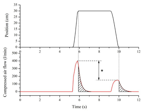
Figure 2.
Compressed air flow when a supply pressure of 600 kPa is used in the working stroke and 300 kPa in the return stroke.
Equation (2) provides the conclusion that the pressure in the cylinder chambers increases up to the maximum value, i.e., the value of the supply pressure, only after reaching the final position. If the supply is cut off at the end of the cylinder stroke and the cylinder is held in its final position, this directly affects the reduction in air consumption, since the pressure in the work chamber is prevented from reaching its maximal value, as shown by the hatched area in Figure 2.
3. Results
To present the advantage of using the cylinder control system with different levels of compressed air pressure in the working and the return stroke, as well as the advantage of holding the cylinder piston in its final position, experiments were performed with universal cylinders with a piston rod on one side, manufactured by FESTO, with different piston diameters of 32, 40, 63, 80, 100 and 125 mm, and a 250 mm stroke. For each of the cylinders, 10 measurements were performed. This was done to measure the savings in compressed air consumption by using the proposed cylinder control with different chamber volumes. Two sets of measurements were performed.
Firstly, compressed air consumption measurements were performed at the supply pressure of 600 kPa, on cylinders supplied by a 5/2-way valve, Figure 1a. This is a common cylinder—supply valve link. The average air consumption results, with relative error 1.2%, are shown in Table 1.

Table 1.
Air consumption results for the system in Figure 1a.
Based on these compressed air consumption results, the savings during other measurements were calculated.
The second set of measurements was performed with the supply pressure Ps+ set at 600 kPa in the working stroke and the lower pressures Ps− at 500, 400 and 300 kPa in the return stroke of the cylinder, Figure 1b. The supply pressure of the cylinder with the clamping cartridge was equal to the supply pressure of the cylinder in the working stroke, i.e., Psk = Ps+ = 600 kPa. Compressed air consumption of the by clamping cartridge depended on the diameter of the used cylinder, i.e., the diameter of the piston rod that was supposed to be held, and it ranged from 0.02 L for the 32 mm piston diameter, up to 0.9 L for the 125 mm piston diameter. The specific components used in these measurements are shown in Figure 1b.
The average air consumption results, with relative error 1.2%, are shown in Table 2.
Table 2.
Air consumption results for the system in Figure 1b.
As was explained in the previous section, if the lower compressed air pressure is used to supply the cylinder chambers, the active force will be lower, and the cylinder piston movement will be slower. The diagrams in Figure 3, Figure 4 and Figure 5 show the experimental results of dependences of velocity of cylinder piston movement on compressed air pressure in the return stroke.
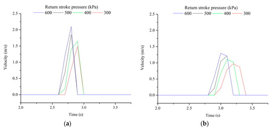
Figure 3.
Velocity of cylinder piston movement. Diameter of cylinder: (a) 32 mm; (b) 40 mm.
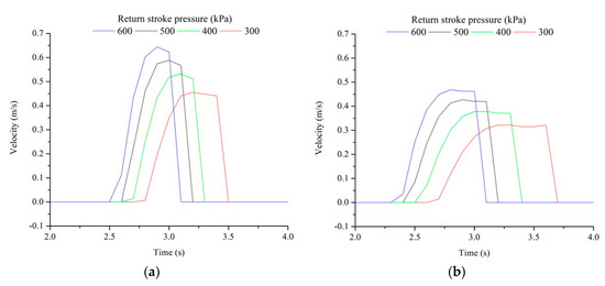
Figure 4.
Velocity of cylinder piston movement. Diameter of cylinder: (a) 63 mm; (b) 80 mm.
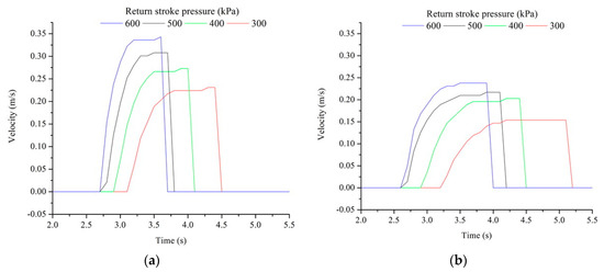
Figure 5.
Velocity of cylinder piston movement. Diameter of cylinder: (a) 100 mm; (b) 125 mm.
4. Discussion
Based on the obtained results of the compressed air consumption measurements from Table 1 and Table 2, a reduction in compressed air consumption can be observed when lower supply pressure is used in the return stroke and when the cylinder is held by a clamping cartridge in accordance with Figure 1b.
Table 3 shows the possible compressed air savings that could be obtained by using different levels of supply pressures in the working and the return stroke, when the unit for holding the cylinder in its final position is used. From Table 3, it can observed that the average savings in compressed air consumption when lower supply pressures are used in the return stroke, and with the use of a clamping cartridge for holding the cylinder in its final positions, are as follows: 25.91% when Ps− = 500 kPa, 29.33% when Ps− = 400 kPa, and 32.7% when Ps− = 300 kPa.
Table 3.
The savings in compressed air consumption after second set of measurements.
Based on the above, and from the perspective of energy savings, it can be concluded that the lower the supply pressure used in the return stroke, the better. This claim has its limitations in the sense that when lower pressures are applied in the return stroke, the stroke itself, i.e., the return of the cylinder to its initial position, slows down, meaning that more time is needed for it to be fully performed. The velocity of cylinder piston movement in the return stroke directly depends on compressed air pressure, Figure 3, Figure 4 and Figure 5. If the velocity of cylinder piston movement is slower, then the duration of movement is longer. The duration of cylinder piston movement in the return stroke, depending on compressed air pressure, is shown in Table 4. The pressure in the return stroke can be lowered, but it needs to remain sufficiently high to ensure the movement of the cylinder.
Table 4.
The duration of cylinder piston movement in the return stroke.
4.1. Cost-Effectiveness
In order to apply the cylinder control system with different levels of compressed air pressure and holding the final position, it is necessary to replace the 5/2-way monostable valve, Figure 1a, with three 3/2-way monostable valves and to install a clamping cartridge, Figure 1b.
The cost-effectiveness of the proposed control is based on the price of FESTO company products for clamping cartridges with designation KP, AZ PNEUMATICA company products for valves, and a cost of compressed air of 0.022 €/m3. The return of investment period (RIP) depends on the saving (%) accomplished by the proposed control and the number of cylinder working cycles per year, or cycle duration. If the cycle duration is shorter, the number of cylinder working cycles per year is higher, when the cylinder works all the time. According to previous assumptions, the number of cylinder working cycles per year (NCWCY) is NCWCY = (52 weeks × 5 days × 2 shifts × 8 h × 60 min × 60 s)/tc, where tc is cycle duration in seconds. Prices of additional components for holding the cylinder in final positions range from €357.60 to €1746.80, and prices for valves range from €26.50 to €46.90, depending on cylinder dimensions.
The diagrams in Figure 6, Figure 7 and Figure 8 show the RIP, depending on the cycle duration and return stroke pressure of the cylinder.
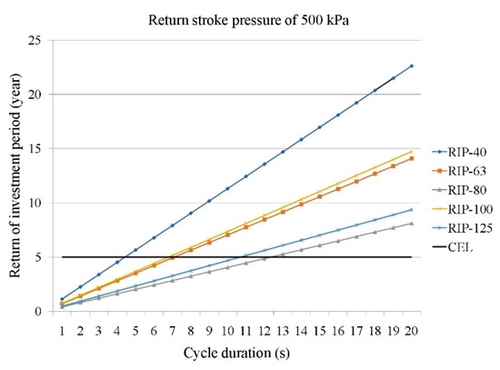
Figure 6.
Return of investment period (RIP) with return stroke pressure of 500 kPa.
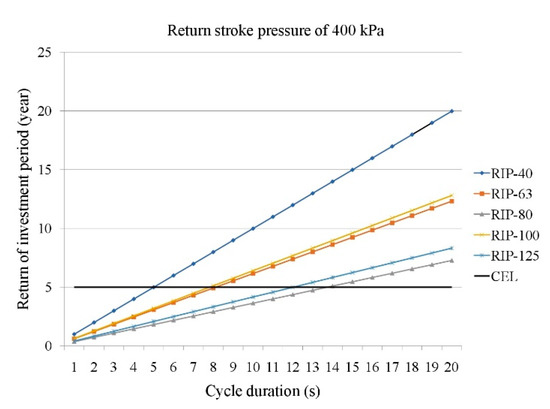
Figure 7.
Return of investment period (RIP) with return stroke pressure of 400 kPa.
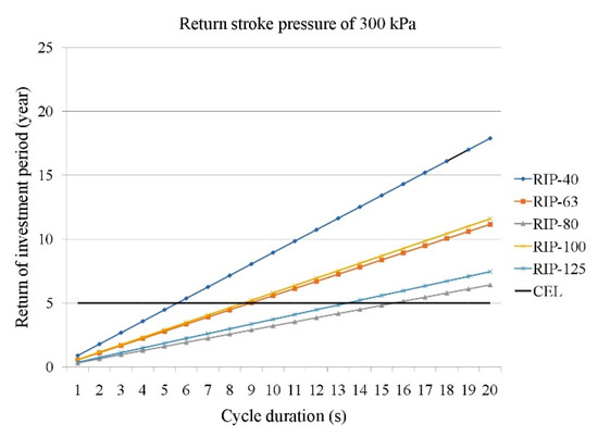
Figure 8.
Return of investment period (RIP) with return stroke pressure of 300 kPa.
The cost-effectiveness limit (CEL) of five years shows the value of cost-effective cycle duration for different cylinders and return stroke pressures. If the RIP is less than CEL, the cycle duration is cost-effective for implementing the proposed cylinder control with clamping cartridge and different levels of compressed air pressure. For pneumatic cylinders with larger chamber volume, cost-effective cycle duration is even longer.
5. Conclusions
The control system of a double-acting cylinder with a piston rod on one side using different pressure levels of compressed air in the working and the return stroke, and with the clamping cartridge for holding the cylinder piston rod in its final positions, shows good characteristics and ensures savings. Savings in compressed air consumption in the proposed system range from 25.54% to 32.97%, depending on the air pressure used in the return stroke. The average savings in compressed air consumption for different cylinders are as follows: 25.91% when Ps− = 500 kPa, 29.33% when Ps− = 400 kPa, and 32.7% when Ps− = 300 kPa. One of the shortcomings of such a system is that a lower cylinder supply pressure in the return stroke leads to a reduced speed of movement of the cylinder piston, which slightly extends the return time and whole cycle duration. With the extension of the cycle duration, the cost-effectiveness of the proposed control decreases, and the RIP becomes higher than five years, regardless of the energy savings in compressed air consumption.
Author Contributions
V.B. and D.S. conceived and designed the experiments; S.D. performed the experiments and analyzed the data; V.B. and S.R. wrote the paper and modified the manuscript. All authors have read and agreed to the published version of the manuscript.
Funding
This research received no external funding.
Conflicts of Interest
The authors declare no conflict of interest.
References
- Blagojevic, V. Contribution to the Development of Efficient Control of Pneumatic Executive Organs. Ph.D. Thesis, University of Novi Sad, Faculty of Technical Science, Novi Sad, Serbia, 2010. [Google Scholar]
- Al-Dakkan, K.A.; Goldfarb, M.; Barth, E.J. Energy saving control for pneumatic servo systems. In Proceedings of the 2003 IEEE/ASME International Conference on Advanced Intelligent Mechatronics (AIM 2003), Kobe, Japan, 20–24 July 2003; pp. 284–289. [Google Scholar]
- Yang, F.; Tadano, K.; Li, G.; Kagawa, T.; Peng, J. Simulation on the Characteristics of Pneumatic Booster Valve with Energy Recovery, AsiaSim 2016, SCS AutumnSim 2016. Commun. Comput. Inf. Sci. 2016, 645, 143–153. [Google Scholar]
- Yang, F.; Tadano, K.; Li, G.; Kagawa, T. Analysis of the Energy Efficiency of a Pneumatic Booster Regulator with Energy Recovery. Appl. Sci. 2017, 7, 816. [Google Scholar] [CrossRef]
- Luciano, E.; Victor, J.; De, N.; Eugênio, B.C. Compressed air saving in symmetrical and asymmetrical pneumatic positioning systems. Proc. Inst. Mech. Eng. Part I 2015, 229, 957–969. [Google Scholar]
- Joshua, J.C.; Christopher, J.N.; Seth, T.; Aaron, J.; Sankaran, M.; Eric, J.B. Energy conservation in industrial pneumatics: A state model for predicting energetic savings using a novel pneumatic strain energy accumulator. Appl. Energy 2017, 198, 239–249. [Google Scholar]
- Wang, Z.; Xiong, W.; Wang, H. Exergy analysis of the pneumatic line throwing system. Int. J. Exergy 2017, 19, 364–379. [Google Scholar] [CrossRef]
- Shen, X.; Goldfarb, M. Energy Saving in Pneumatic Servo Control Utilizing Interchamber Cross-Flow. J. Dyn. Syst. Meas. Control 2007, 129, 303–310. [Google Scholar] [CrossRef]
- Yang, A.; Pu, J.; Wong, C.B.; Moore, P. By-pass valve control to improve energy efficiency of pneumatic drive system. Control Eng. Pract. 2009, 17, 623–628. [Google Scholar] [CrossRef]
- Šešlija, D.; Čajetinac, S.; Blagojević, V.; Šulc, J. Application of pulse width modulation and by-pass valve control for increasing energy efficiency of pneumatic actuator system. Proc. Inst. Mech. Eng. Part I 2018, 232, 1314–1324. [Google Scholar] [CrossRef]
- Bartyś, M.; Hryniewicki, B. The Trade-Off between the Controller Effort and Control Quality on Example of an Electro-Pneumatic Final Control Element. Actuators 2019, 8, 23. [Google Scholar] [CrossRef]
- Kanno, T.; Hasegawa, T.; Miyazaki, T.; Yamamoto, N.; Haraguchi, D.; Kawashima, K. Development of a Poppet-Type Pneumatic Servo Valve. Appl. Sci. 2018, 8, 2094. [Google Scholar] [CrossRef]
- Harris, P.; Nolan, S.; O’Donnell, G.E. Energy optimisation of pneumatic actuator systems in manufacturing. J. Clean. Prod. 2014, 72, 35–45. [Google Scholar] [CrossRef]
- Cummins, J.J.; Barth, E.J.; Adams, D.E. Modeling of a pneumatic strain energy accumulator for variable system configurations with quantified projections of energy efficiency increases. In ASME/BATH 2015 Symposium on Fluid Power and Motion Control; American Society of Mechanical Engineers: Chicago, IL, USA, 2015; V001T01A055.ASME. [Google Scholar]
- Luo, X.; Wang, J.H.; Sun, H.; Derby, J.W.; Mangan, S.J. Study of a new strategy for pneumatic actuator system energy efficiency improvement via the scroll expander technology. IEEE/ASME Trans. Mechatron. 2013, 18, 1508–1518. [Google Scholar] [CrossRef]
- Luo, X.; Sun, H.; Wang, J.H. An energy efficient pneumatic-electrical system and control strategy development. In Proceedings of the 2011 American Control Conference, San Francisco, CA, USA, 29 June–1 July 2011. [Google Scholar]
- Nehler, T. Linking energy efficiency measures in industrial compressed air systems with non-energy benefits—A review. Renew. Sustain. Energy Rev. 2018, 89, 72–87. [Google Scholar] [CrossRef]


© 2020 by the authors. Licensee MDPI, Basel, Switzerland. This article is an open access article distributed under the terms and conditions of the Creative Commons Attribution (CC BY) license (http://creativecommons.org/licenses/by/4.0/).