Article

Fluidised Bed Gasification of Diverse Biomass Feedstocks and Blends—An Overall Performance Study

University of Grenoble Alpes, CEA, LITEN, DTBH, 38000 Grenoble, France
*
Author to whom correspondence should be addressed.
Energies 2020, 13(14), 3706; https://doi.org/10.3390/en13143706
Submission received: 15 June 2020 / Revised: 15 July 2020 / Accepted: 16 July 2020 / Published: 18 July 2020
(This article belongs to the Special Issue Thermochemical Conversion of Biomass and Waste)

Abstract

:
The aim of this work is to investigate the fluidised bed gasification of several pure and blended feedstock prepared in the form of pellets: oak bark, two bark/wheat straw blends (85/15 and 50/50 wt%) and lignin residue remaining from bioethanol production. Gasification conditions were defined to be representative of dual fluidised bed ones (steam gasification at 850 °C, followed by air combustion of the char). The cold gas efficiency (77–81%), gas composition and tar content (0.9–2.3 g/kgdaf) are close for the gasification of bark and the two bark/wheat straw blends. For lignin residue, the cold gas efficiency is lower (71%), and the tar content is 9.1 g/kgdaf. The agglomeration propensity is much higher for lignin residue than for the other feedstock. This was put into evidence with in-bed temperature measurements at different levels, and confirmed with post-test size screening of the bed material particles. The 50/50 wt% bark/wheat straw blend seems to undergo defluidisation in combustion, however followed by refluidisation of the bed. These findings were also well correlated with a predictive model for defluidisation.

1. Introduction

Fluidised-bed gasification is one of the major process to reach a high gas product yield from a large panel of carbonaceous resources (biomass, wastes). According to the type of oxidant gas (air, O2, H2O, CO2), to the type of fluidised bed (bubbling, circulating, dual), and to the operation conditions (temperature, pressure), different composition of gas can be obtained. For instance, autothermal gasification with O2, or so-called ‘allothermal’ gasification in a dual fluidised bed, generally performed with steam, can allow producing an almost inert gas free synthesis gas, well-adapted for further biofuel or chemical product synthesis [1]. Nonetheless, tar species present in the synthesis gas should always be removed to reach very low content values, in order to avoid catalyst poisoning in the synthesis process. The gas composition should also be adapted to reach the synthesis process specifications (target H2/CO ratio usually). This can be performed by adapting the gasification conditions and the type of bed material [2], or by using catalysts in fixed beds after the gasification step [3].
The use of biomass with high ash content (higher than about 3%), such as forestry or agricultural residues is more problematic than the use of woodchips or wood pellets especially because of their agglomeration propensity. The enlargement of the biomass feedstock panel is still of high importance so as to bring more flexibility for any gasification plant toward the available biomass resources. The agglomeration problematic concerns in particular the biomass with high alkaline (K, Na) and Si contents. Indeed, these elements tend to form low temperature melting phases (carbonates, silicates, or molten salts), which constitute the key driver to bed agglomeration [4], followed by defluidisation, and possible shut down of the installation. Two extreme types of agglomeration have been identified [5]: ‘melt-induced agglomeration’ in which bed material particles are made to stick together by a melt phase coming from the biomass ash, and ‘coating induced agglomeration’, in which a physico-chemical interaction between solid ash particles and bed material particles induces the formation of a liquid coating at the surface of the bed material particles. Agglomeration is then initiated when necks are formed between the coatings of several bed particles.
Several agglomeration counteraction strategies have been tested in existing reactor technologies. They can be classified into [6]: 1. Use of additives which chemically react with ash elements so as to avoid the formation of silicates; 2. adaptation of the bed material which can chemically participate in the agglomeration phenomena; and 3. operational methods such as gas velocity increase, bed temperature lowering; or 4. co-feeding of several organic waste types. However, it is important to note that the operational methods also affect the overall gasification efficiency, with, for instance, a negative impact of a too low reactor temperature. Siddiqui et al. [7] managed to adapt the design and operational protocol of their downdraft gasifier in order to avoid clinker formation in garden waste gasification, at the same time as maximising the gasification efficiency.
Co-feeding and blending of problematic feedstock (alkaline-rich) with coal or woody biomass has already been tested as an agglomeration counteraction strategy in several fluidised bed facilities and industrial plants, mainly in combustion, but also sometimes in gasification, usually performed in autothermal conditions with air as fluidising gas [8,9]. Agglomeration tendency can be detected online, with temperature and/or pressure drop measurements; it can also be confirmed after cooling of the reactor and removal of the bed material, by visual observations and SEM (scanning electron microscopy) associated with EDS (energy dispersive spectroscopy) to analyse the composition of the molten phases [9]. Fryda et al. [10] investigated the agglomeration propensity of one energetic crop and one agricultural residue during their fluidised bed gasification in air. Their study interestingly associated the screening of bed material particles and observations of the agglomerates, together with thermodynamic equilibrium simulations for a better comprehension of the chemical reactions.
However, the studies on gasification of biomass blends are most often justified by feedstock flexibility considerations, and not by agglomeration problem. Pure steam gasification, in a dual fluidised bed or in similar allothermal conditions, of biomass blends, has been only scarcely investigated, and then especially with straw/wood blends [11,12]. The focus of these articles is mainly put on gasification efficiency and product gas tar content.
In the present article, we aim at investigating the fluidised bed gasification of two oak bark/wheat straw blends, of the same oak bark alone, and also of an atypical biomass industry coproduct: lignin residue remaining from bioethanol production. Gasification conditions were defined to be representative of dual fluidised bed ones (steam gasification followed by air combustion of the char). The present study investigates both the gasification efficiency (measured with product gas yields and tar content), and the agglomeration propensity of the different feedstock. The latter is detected online with temperature measurements at three different levels of the fluidised bed, and quantified with size analyses of the bed material particles after gasification/combustion steps. At last, these agglomeration results are put into relation with a predictive model for defluidisation.

2. Materials and Methods

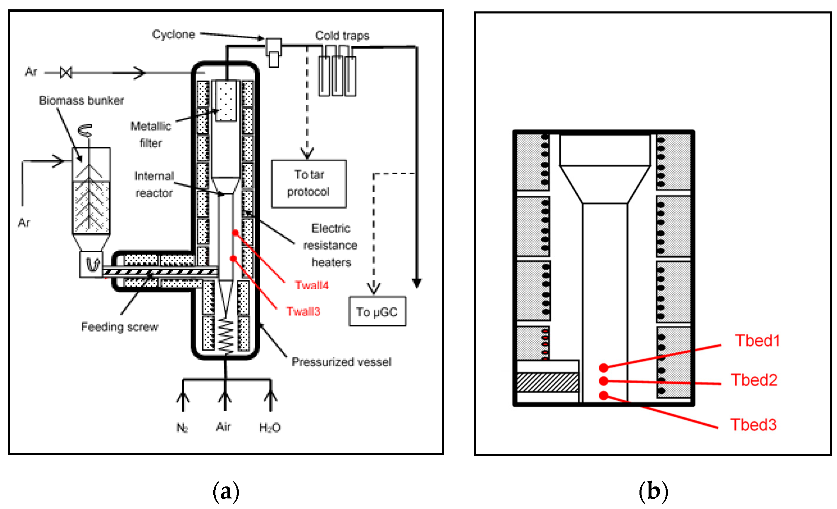
2.1. Description of the Facility

The fluidised bed device is shown in Figure 1a and was described in detail in a previous publication [13]. The device is composed of an internal reactor and feeding screws surrounded by an external vessel designed to sustain a pressure of 40 bars. The internal reactor is heated by nine independent electric resistance heaters. The biomass conveying screw can also be heated by two heating elements. The maximum temperature is 1000 °C. The fluidised bed reactor is composed of a lower part—0.124 m internal diameter, 0.95 m height—followed by a disengagement zone of 0.20 m internal diameter and 1.54 m height. Metallic filters are mounted in the upper part of the freeboard. A heated cyclone can also remove the remaining particulates at the outlet of the reactor.
Gas temperature in the bed is measured with three thermocouples located at 6 cm, 8 cm and 10 cm respectively from the gas distributor, for the experiments with beech, lignin residue and bark. For the last two experiments with bark/wheat straw blends, the internal reactor had to be repaired and the thermocouples were then located at 5 cm, 10 cm and 15 cm respectively from the gas distributor (Figure 1b). The biomass is stored in a pressurised bunker and is introduced in the reactor with two feeding screws: a dosing one followed by a conveying screw with a high rotation velocity of 70 rpm. Argon is injected in the bunker to avoid syngas back flow.
For the present experiments, the fluidising gas was steam mixed with N2 (biomass gasification) or air mixed with N2 (char combustion). The gas distributor is a plate supplied with 12 nozzles with 4 holes of 1 mm diameter on each of them.
At the reactor output, gas temperature is kept at 600 °C until it flows through three cold traps in series, where water and tars are condensed. These traps are cooled at decreasing temperatures between ambient and −5 °C approximately. The condensed water flowrate is measured online owing to a pressure drop transducer measuring the height of condensed water in a column.
Gas composition is analysed online using a micro gas chromatograph (µGC) coupled with a thermal conductivity detector (TCD). The analyser is equipped with four columns. The compounds which can be detected are: Ar, O2, CO2, CO, CH4, N2, H2, C2H2, C2H4, C2H6, C3H6/C3H8, C6H6 (benzene), C7H8 (toluene), C8H10 (xylene and ethylbenzene), H2S, COS, H2O in vapor phase. An analysis is performed every 3 min. The lower limit of quantification is 3 ppm for each gas.
Tar sampling is performed following the tar protocol method [14] using isopropanol as solvent. Tar species are then identified and quantified by GC-FID (gas chromatography–flame ionization detection).

2.2. Biomass Characterization

Several types of biomass feedstock were tested in the fluidised bed gasification experiments: beech wood chips as a reference biomass, and pellets of oak bark, of lignin residue (coming from bioethanol production), and of two blends of bark/wheat straw (50/50 wt% and 85/15 wt% respectively). The pellets were 6 mm in diameter and 15 mm in length. These blends were proposed to allow the gasification of wheat straw in blends with a limited agglomeration risk, following a methodology similar to that described in [15]. Agglomeration tendency of bark, wheat straw and blends, was first investigated with thermodynamic calculations, then with laboratory experiments of ash or pellet annealing and quench, followed by SEM-EDS analyses to detect liquid ash formation. These preliminary results tended to show that the 85/15 wt% bark/wheat straw blend could be gasified with a limited agglomeration risk (low liquid fraction in the ash), while the 50/50 wt% bark/wheat straw blend presented a higher liquid ash formation. However, it was decided to test both blends at pilot scale. On the other hand, it was decided not to test wheat straw alone because of its very high propensity to agglomeration [16].
The moisture and ash content, lower heating value (LHV) and elemental composition of the feedstock are shown in Table 1. The composition of the parent wheat straw is also shown. Carbon, hydrogen, nitrogen, sulphur and oxygen contents were measured with an Elementar Vario EL cube analyser. The main ash-forming elements were directly measured by inductively coupled plasma atomic emission spectroscopy (ICP−AES) after microwave digestion of the raw biomass in HNO3/HF/H2O2 acid and fusion in lithium tetraborate for Si. Their mass content in the dry biomass (in ppm) is indicated in Table 1. Note that for the oxygen content measurement, the sample is heated up to 1150 °C in He. At this temperature, a part of the released oxygen probably comes from the decomposition of inorganic carbonates or oxides natively present in biomass. So this oxygen content is higher than what would be calculated by difference considering the ash content and the C, H, N, S and Cl contents.
Bark and bark-wheat straw blends have close ash contents (8–9%) at 815 °C, while the ash contents of lignin residue and beech wood are lower (3.5% and 0.7% maximum respectively). For lignin residue, the main inorganic elements are: Na > K > Si and Ca, whereas for bark and blends, they are: Ca > Si > K.

2.3. Analyses of the Solid and Liquid Products

The solids collected in the reactor bed after gasification and combustion experiments (as detailed in Section 2.4) were subsequently recovered and sieved into different size fractions, in order to detect agglomeration: <0.2 mm; 0.2–0.5 mm corresponding to the initial bed material particle size (olivine); 0.5–0.63 mm; 0.63–0.9 mm; 0.63–2.5 mm; 2.5–4.5 mm; >4.5 mm. Different types of analyses were performed on these solids:
  • Measurement of ash content at 815 °C (on the solids recovered after gasification);
  • Powder X-ray diffraction (P-XRD) analysis was used to identify the presence of liquid and crystalline phases on a D8 Bruker Advance with Cu Kα radiation (40 kV, 30 mA), equipped with a fast Lynxeye detector. The Bruker DIFFRAC.EVA software together with the PDF-4 reference database were used for the phase identification;
  • Scanning electron microscopy (SEM): microstructures were also observed on a Philips XL30 SEM coupled with an Oxford Instruments EDX system (INCA software) to obtain semi-quantification of the chemical composition of each phase. The residues to be studied were embedded under vacuum in epoxy resin and polished with water-free lubricants. The samples were coated with graphite to make them conductive allowing SEM analysis.

2.4. Method and Operating Conditions of the Fluidised Bed Experiments

The fluidised bed experiments were intended to evaluate gasification efficiency, and to investigate the agglomeration propensity for several feedstock and blends in conditions representative of dual fluidised bed ones. The criteria considered for representativeness were first of all thermochemical ones: temperature and gaseous oxidant type. However, some similarities were also aimed concerning fluid dynamic, and particularly with the fluidisation ratio. These aspects will be highlighted below.
Five tests were performed in similar conditions, for each of the biomass listed in Table 1. The tests were set in two parts: the first one for simulation of the conditions in the gasifier of the dual fluidised bed (850 °C, steam gasification); the second one for simulation of the conditions in the combustor part (950 °C, air). In-between and after combustion, the reactor was left to cool down. It was then opened and the in-bed solid residue was taken out of the reactor, and sieved. The particle size distribution was analysed in order to detect a possible agglomeration. This method was used by other authors [10], who noticed a shift toward higher particle size with agglomeration. Sampling was also performed for further analyses (as explained in Section 2.3). The remaining solid residue was poured again in the reactor after gasification to perform the combustion. On the other hand, the residue remaining on the metallic filters and in the cyclone was removed and weighed after gasification, and after combustion.
Before each test, 5 kg of fresh olivine, coming from Austria, were poured into the reactor. Its particle size was between 200 and 500 µm. For both gasification and combustion, Ar—flowrate of 10.1 NL/min—was fed in the bunker and its injection was kept constant all along the experiment. The set-point pressure in the bed was 1.5 bar.
Gasification:
The reactor, gas input and output lines were first electrically heated to their set points (850 °C). The fluidising gas was steam (0.435 g/s or 32.5 NL/min), which was mixed with N2—flowrate of 8–12 NL·min−1—so as to reach a gas velocity in the bed of 0.14–0.17 m·s−1. So the fluidisation ratio (superficial velocity to minimum fluidisation velocity) was between 2.5 and 3 (Table 2). In the gasifier part of dual fluidised beds, the oxidant is usually steam, and temperature is around 850 °C. The gasifier is a bubbling fluidised bed, with a fluidization ratio of about 4 [17].
The biomass feeding rate set value was adjusted for each biomass in order to keep a constant steam/carbon ratio (Table 2). However, the real mean feeding rate was calculated after weighing the biomass in the bunker before and after each test. The real steam/carbon ratio was then in the range 0.88–0.98 g/g.
The duration of each gasification experiment was set in order to get approximately the same mass of ash accumulated in-bed (between 430 and 500 g of ash, corresponding to about 10% of the olivine mass), to be able to compare the agglomeration propensity of each feedstock on a common basis regarding ash quantity (Table 2). This was possible for all biomass except from beech wood because of its too low ash content.
Combustion:
The reactor was first electrically heated to its set points (800 or 850 °C). The fluidising gas was air (40 NL·min−1), which was mixed with N2 to increase the in-bed velocity. The fluidising ratio was respectively equal to 4.0, 3.9, 3.2, 4.0 and 3.8 for beech wood, lignin residue, bark, 85/15 wt% bark/wheat straw blend and 50/50 wt% bark/wheat straw blend. When air was introduced in the reactor, its temperature increased because of exothermic reactions. During the experiments, the temperature setpoint and/or air flowrate were adjusted so that the in-bed temperature remains as close as possible to 950 °C, in order to approach the temperature in the combustor part of dual fluidised beds. Moreover, in this type of reactor, the fluidising ratio in the combustor part is around 7 at the bottom, under the secondary air injection level, and 10 times higher in the riser part above [17]. So our conditions rather approach those of the bottom of the combustor, where the char is conveyed from the gasifier.
For all experiments except from the 1st one (beech sawdust), He (100 NL/min) was mixed with product gas before µGC analysis. It was used as a tracer gas to quantify the total dry gas flowrate coming out of the reactor. For the first experiment, N2 was used as tracer gas, however its inlet flowrate was not so well precisely quantified which led to more uncertainties for the total flowrate than with helium.

2.5. Thermodynamic Calculations

Calculations were performed by minimisation of the Gibbs free energy of the total system, considering as input data the initial quantities of the main elements (C, H, O, N, S, Cl, Si, Ca, K, P, Mg, Al, Fe, Na, Mn), the temperature and the pressure of the system. The atmosphere (steam for gasification, air for combustion) was also considered in the calculations. For gasification, the relative inlet flowrates of biomass and steam into the reactor (Table 2) and the biomass composition (Table 1) were considered to settle the input data of the calculations. For combustion, the char was already present in the reactor at the beginning of the test, and then progressively oxidised by air as explained before. As the elemental composition of the char was not known, the composition of the raw biomass was considered as a first approach in the calculation. The quantity of air relatively to biomass was determined on the basis of the mean production of CO and CO2 during the combustion of the in-bed char (presented in the results Section 3.1), considering the following reaction:
CH x O y + ( 1 + x 4 y + z 2 ) O 2 zCO + ( 1 z ) CO 2 + x 2 H 2 O
The software Factsage 7.1 [18] was used with three databases:
  • FactPS (stoichiometric solid, liquid and gas compounds).
  • FTSalt (pure salts and solutions).
  • GTOX5.1 (solid and liquid solutions) especially developed for oxide biomass ash systems [19].
These calculations were performed with the objective to evaluate if liquid ash was present in the conditions of the biomass gasification and char combustion tests, and to predict its mass fraction.

3. Results and Discussion

The results of each experiment are presented in this section. First, a focus is made on temperature measurement in the bubbling fluidised bed, both during biomass gasification and char combustion tests. The analysis of in-bed temperature at different heights can give information on possible poor fluidisation [20]. Then, gasification results for each feedstock are compared (product gas yield, composition and tar content). The characterisations of the solid residues sampled after gasification, and recovered after combustion, are presented in Section 3.4. At last, the results of the thermodynamic simulations are presented and compared to the experimental ones.

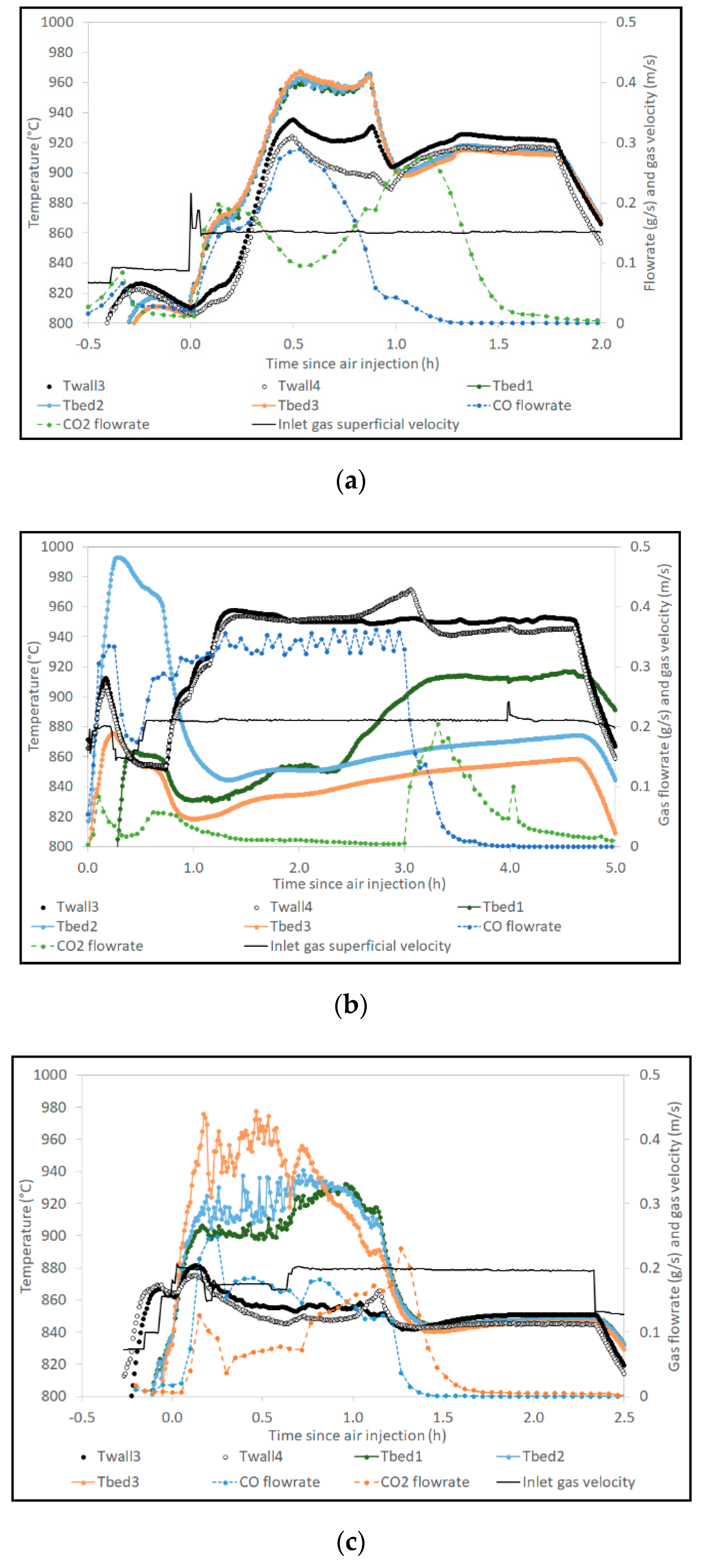
3.1. Temperature Measurements

As explained before, in gasification experiments, the wall temperatures in the fluidised zone were regulated at about 850 °C with electric heating. The three in-bed temperature values were very close (less than 1 °C difference) in all gasification experiments except from the one with lignin residue. This is a sign that for all the other feedstock, the fluidisation was smooth with a uniform in-bed temperature. The in-bed temperature was a bit lower than the wall temperature, with a value between about 830 and 845 °C. For the experiment with lignin residue, a clear shift appeared between the three measurements after about 3 h feeding, although there was no change in wall temperature, pressure or gas flowrate. The gas temperature became then lower in the bottom part of the bed, with a difference of about 5 °C with the top of the bed. This can be a sign of degraded fluidisation, and could be linked to the beginning of agglomeration.
The temperatures measured in the fluidised bed zone are shown in Figure 2 for the combustion of chars from bark, 50/50 wt% bark-wheat straw blend and lignin residue as examples. ‘Twall3’ and ‘Twall4’ are the temperatures measured on the external wall of the reactor at two axial locations (Figure 1a). ‘Tbed3’, ‘Tbed2’ and ‘Tbed1’ are the in-bed gas temperature measurements, starting from the bottom of the bed (Figure 1b). The inlet gas superficial velocity, as well as the produced CO and CO2 flowrates, are plotted on the figures. For each combustion experiment, the values of Tbed1, Tbed2 and Tbed3 increase as soon as air is fed into the reactor, and reach higher values than Twall3 and Twall4, which is characteristic of exothermic oxidation reactions in the bed zone. After about 1–2 h, the in-bed temperatures decrease to values lower than Twall3 and Twall4, whereas the temperatures measured at the top of the reactor, in the metallic filter zone, slightly increase (not shown on the figures). This is due to combustion of the char entrained on the filters, after that the char in-bed has been completely oxidised.
In most cases, the CO flowrate is higher than the CO2 one in the whole first part of the oxidation, and the CO2 flowrate is higher only at the end. This is probably because stoichiometry of air relatively to char is too low for a complete oxidation.
The maximum temperature difference in the bed in the first part of the combustion test is very dependent on the combustion test: 10 °C for char from beech and bark, 25 °C for char from 85/15 wt% bark/wheat straw blend (not shown), 70 °C for char from 50/50 wt% bark/wheat straw blend, more than 100 °C for char from lignin residue.
This temperature difference in the bed can be a sign of heterogeneous fluidisation, and thus of possible bed partial agglomeration. However, after the combustion in bed is finished, the three in-bed temperature measurements converge toward the same value again for the char from beech, bark and blends. For the char from lignin residue, the temperature values remain far from one another (Figure 2b). These results can be linked with the observations of the solid bed material after the tests, which are presented in Section 3.4: Large agglomerates for lignin residue, and almost none for the blends.

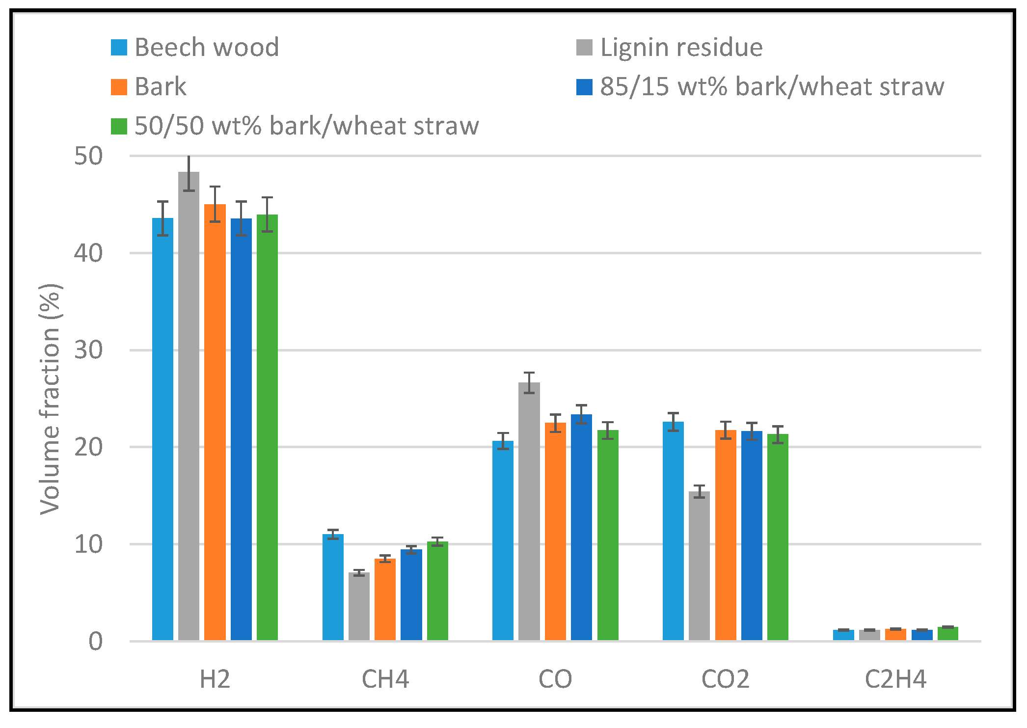
3.2. Product Gas Yield and Composition in Gasification Experiments

First of all, elementary C, H and O mass balances were calculated for each feedstock gasification. These allow checking the overall accuracy of the results, and giving information about the distribution of the elements in the products (especially carbon which only comes from biomass).
At the inlet, we considered: the total mass of biomass fed into the reactor, together with elemental composition and moisture content (Table 1), and the mass of steam fed into the reactor.
At the outlet, we considered:
  • The mass of dry gas obtained by integration over the whole gasification experiment (composition analysed by µGC, flowrate obtained with tracer gas method),
  • The mass of water trapped in condensers,
  • The mass and composition of condensable tar trapped in ‘tar protocol’,
  • The mass of fly residue on filters and cyclone recovered after gasification (this residue was supposed to be composed of carbon and ash only, and the ash content was measured on samples),
  • The mass of solid remaining in the bed determined with the combustion experiment, by quantifying the CO/CO2 released then (µGC analysis and tracer gas method).
For hydrogen and oxygen, the elemental balance was always incompletely closed with 7 to 20% lack. The difference to 100% was always the same for H and O, which is explained by the incomplete quantification of water at the outlet of the reactor. Indeed, the residual flow of water (steam) passing through the cold traps is not well quantified.
The carbon balance is presented in Figure 3. The elemental balance is very close to 100% for every experiments, except from the first one with beech sawdust. This is attributed to the uncertainty of gas flowrate calculation using N2 as tracer gas. This is one reason why helium was used for the subsequent experiments, giving better results.
The fraction of carbon in product gas is very similar for bark and for the 85/15 wt% bark/wheat straw blend (around 75%). It is a bit lower for the 50/50 wt% bark/wheat straw blend (69%), and for lignin residue (64%). Lignin residue is richer in lignin than the other feedstock studied here. The lower fraction of carbon in gas for this feedstock can be linked to the lower volatile content, and to the higher fixed carbon of lignin, compared to hemicellulose and cellulose [21]. This could also explain why the fraction of carbon in char is between 20 and 25% for pelletised biomass, and seems to be a bit higher for lignin residue than for bark and bark-wheat straw blends. The fraction of carbon in fly residue (filter + cyclone) represents less than 7% of initial carbon. It seems to be higher for pellets than for sawdust, which is also observed for the fraction of C in char. This could be due to the initial form and size of the biomass, the pellets being globally heated at a slower rate than wood chips because of the internal thermal transfer limitation, which can lead to a lower gas yield [22]. The fraction of carbon in tar is low (less than 1% for all feedstock except from lignin residue with about 3%).
The yield of each gas species analysed by µGC was determined all along each gasification experiment. So as to easily compare the results obtained with all feedstock, mean value of gas species yields and fractions were calculated for each experiment. The mean in-bed temperature was similar for all feedstock (834–840 °C). The mean dry gas composition (main gas species: H2, CH4, CO, CO2, C2H4) is presented in Figure 4. The results for beech sawdust, bark and the two bark/wheat straw blends are very close. The only differences concern CH4 fraction, which seems to be slightly higher for beech, and slightly increasing with fraction of wheat straw blended to bark. Our results for bark/wheat straw blends are in good agreement with the dry gas composition obtained after the gasification of a 40% straw/60% wood blend in a dual fluidised bed gasifier [11]: 38.5% H2, 19.6% CO, 23.1% CO2, 9.9% CH4. The main differences come from lignin residue compared to the other feedstock: higher H2 and CO fractions, and lower CH4 and CO2 fractions. Tian et al. [21] investigated steam gasification of cellulose, hemicellulose, and lignin in a downdraft gasifier, and showed that the gas coming from lignin, at 900°C, was much richer in H2 and poorer in CH4, which is in agreement with our results. On the other hand, the authors [21] found out that CO content in gas coming from lignin was lower than in gas coming from hemicellulose or cellulose, which is not in agreement with the present results.
The mean yields are presented in Figure 5a for main gas species, and in Figure 5b for minor ones. Beech sawdust results are not represented since the yields were probably underestimated, with a poor carbon balance as shown previously.
The differences observed between gas composition of lignin residue and of the bark containing feedstock are also visible for gas yields (higher H2 and CO yields, and lower CH4 and CO2 yields for lignin residue). On the other hand, the H2 yield seems to slightly decrease as the fraction of wheat straw blended to bark increases. These results concerning bark and bark/wheat straw blends seem to be in agreement with previous comparative results of wheat straw and wood steam gasification [23], which tended to show that wheat straw gave a higher CH4 yield and a lower H2 one than woody biomass.
For the minor gas species (Figure 5b), the main differences are also for lignin residue compared to the other feedstock, with higher yields in C2H2, H2S, COS, C6H6 and C7H8. In particular, the benzene yield is nearly twice for lignin residue.
The cold gas efficiency (CGE), and LHV and yield of the dry product gas are presented in Table 3 for each feedstock. The CGE is calculated as follows (Equation (2), in which Qi is the mass flowrate of i in kg·s−1 and LHVi is the lower heating value of i in J·kg−1):
CGE = i ( Q i × L H V i ) Q b i o m a s s × L H V b i o m a s s
Two values of CGE were calculated: the first one considering all gas species analysed by µGC, and the other without considering benzene and toluene which could be cleaned before the final synthesis, in a biomass-to-liquid process for instance.
For lignin residue, the cold gas efficiency is the lowest (66% without considering benzene and toluene against 73–78% for bark and blends), although the product gas LHV and yield are similar to those of the other feedstock. This is mathematically linked to the higher value of lignin residue LHV (Table 1), which induces a lower cold gas efficiency (CGE) even if the energy content of the product gas is similar to the value for the other feedstock. The difference in CGE between lignin residue and the other feedstock is higher considering the product gas without benzene and toluene, as their yields were shown to be significantly higher for lignin residue (Figure 5b). The lower CGE for lignin residue can be linked to a lower fraction of carbon in gas species than for the other feedstock (Figure 3). Indeed, the carbon fraction to gas phase in gasification was shown to be much lower for lignin than for cellulose and hemicellulose [24]. On the other hand, as the fraction of wheat straw in blend with bark is higher, the CGE tends to slightly decrease, which is linked to the decrease of product gas yield.

3.3. Tar Content and Composition

The condensable tar production (without considering BTX: benzene, toluene, xylenes), as determined with tar protocol, is shown in Figure 6 for each feedstock (in g/kg of daf biomass). The tar molecules were classified according to their number of aromatic rings. The ‘other’ class is composed of nitrogen and sulphur-containing tars (pyridine and thiophene respectively). Lignin residue clearly leads to a higher tar production (19 g/kgdaf), than all the other biomass, for which the tar production is 4 g/kgdaf at maximum. The highest contribution always comes from molecules with 2 aromatic rings, naphthalene being the major contributor, followed by acenaphtylene. The two main molecules with one aromatic ring are indene and styrene. The ‘3 aromatic rings’ class stands for phenanthrene, anthracene and fluoranthene, and the ‘4 aromatic rings’ for pyrene.
The condensable tar and BTX concentrations in dry gas are indicated in Table 4. For beach, bark and bark-wheat straw blends, the BTX content is significantly higher than the condensable tar one. For lignin residue, the BTX content is still higher but closer to the condensable tar content. In agreement with the results in Figure 6, the highest tar concentrations in dry gas are for lignin residue. This result is in agreement with CO2/steam gasification results obtained in a dual fluidised bed with the same feedstock (oak bark and lignin residue) [25]: even if the gasification was performed at higher temperature for lignin residue, the tar content was significantly higher than for oak bark.
On the other hand, the tar contents for bark and bark/wheat straw blends are not much different. The same tendency was observed in dual fluidised bed gasification of wood and wood/wheat straw blends, which showed that the biomass type had a low influence on tar content compared to process parameters, such as gasification temperature [12]. The authors measured a gravimetric tar concentration of 2–3 g/Nm3 for a gasification temperature of 845 °C, which is similar to our results. Moreover, the major tar molecule class was that comprised of naphthalene and 1 and 2-methylnaphthalene, followed by the class of HAP (without naphthalene). This is also in agreement with the present results.

3.4. Characterisation of the Solid Residue

The particle size distribution of the solid residue was investigated after gasification and after combustion with the objective to find out if some agglomeration happened during the tests.
For gasification, the mass of solid residue determined in each particle size range is reported in Figure 7, after dividing it by the mass of input dry biomass. The ash content of the gasification residues according to their particle size range is shown in Table 5. For combustion, the mass of ash residue is directly reported in Figure 8. In both cases, the mass of residue recovered in the 200–500 µm range is not shown, as it is much higher than the others, being the range in which most olivine particles remain. Moreover, the ash content after gasification is always higher than 93% (Table 5), assessing that it mainly contains olivine.
After gasification, a distinct pattern can be observed between beech wood on the one hand, and the other biomass on the other hand. Indeed, beech wood was fed as millimetre-size particles which produced a much lower fraction of larger residue particles (>0.5 mm) than the pelletised biomass. The mass of fine particles in the <0.2 mm range was unfortunately unavailable for beech wood. For the other feedstock, it represents a significant fraction of residue after gasification. This range can contain fines coming from biomass but also from olivine attrition. Indeed, P-XRD analyses showed the presence of Mg1.7Fe0.3SiO4 and MgSiO3, which are characteristic of olivine. For all feedstock but beech wood, the fraction of residue particles with size higher than 0.5 mm was majority. Only particles with a size higher than 4.5 mm can be considered as agglomerates, and these were only observed after lignin residue gasification. Slight agglomeration was indeed visually observed after lignin residue gasification (large particles composed of sticked olivine particles). These findings are in good agreement with the online measurements of in-bed temperature during gasification.
After combustion, all particles with a size higher than that of olivine (0.5 mm) could be considered as formed by agglomeration, and especially the largest ones (over 0.9 mm). For beech wood, bark and the 85/15 wt% bark-wheat straw blend, the mass of particles larger than 0.5 mm is quite low (less than 32 g—Figure 8). It is a bit higher for the 50/50 wt% bark-wheat straw blend (about 80 g) and much higher for lignin residue (1230 g). The observation of the largest particles from the 50/50 wt% bark-wheat straw blend show the presence of some agglomerates of olivine particles, but also of some white particles, which seem to contain biomass ash only. Concerning lignin residue, the largest particles seem to be essentially agglomerates of olivine particles.
Defining the agglomeration rate as the ratio between the mass of residue with a size higher than 0.5 mm after combustion and the input mass of inorganic material (olivine + biomass ash), its values are: under 1% for beech wood, bark, and the 85/15 wt% bark-wheat straw blend, 1.7% for the 50/50 wt% bark-wheat straw blend, and 32% for lignin residue. Here again, these results are well correlated to the temperature heterogeneity in the bed during combustion. Especially it was noticed that it was maintained until the end of the combustion for lignin residue, which presents a much higher agglomeration rate, contrary to the other feedstock.
The observation and analysis of agglomerates coming from lignin residue, both after gasification and combustion, show that the olivine grains are surrounded by phases enriched in Mg (from olivine) and Na (from lignin) (Figure 9). This is a sign that a chemical reaction happened between the ash from lignin residue and olivine.

3.5. Prediction of Defluidisation and Comparison with Experimental Results

Fryda et al. [10] observed that the defluidisation temperature determined with their experiments was slightly higher than the one calculated with thermodynamic equilibrium simulations, and attributed this discrepancy to the need for a critical amount of slag before defluidisation. Balland et al. [26,27] introduced the criteria of ‘critical liquid ash volume fraction in bed’ from which bed defluidisation happens. Moreover, the authors derived from a whole set of results from biomass gasification experiments and experiments with simulants at ambient temperature, a proportional relation linking this critical liquid fraction to the ratio of the superficial gas velocity over the minimum fluidisation gas velocity:
τ L , c = U g U m f
  • τL,c: critical liquid volume fraction (vol% of bed material)
  • Ug: superficial gas velocity (m/s)
  • Umf: minimum fluidisation velocity (m/s).
Note that this relation was established for a fluidisation ratio (Ug/Umf) comprised between 2 and 6, similarly to the conditions of our gasification and combustion experiments.
From this proportional relation, the same authors [26,27] proposed a semi-empirical relation to predict the time for complete defluidisation:
t d e f = m s × ρ L ( T ) × U g Q b i o × τ a s h × X L ( T ) × ρ s × U m f × 100
  • tdef: time before complete defluidisation (h)
  • ms: mass of bed material (kg)
  • ρL(T): density of the molten ash at operating temperature T (kg/m3)
  • ρs: density of the bed material (kg/m3)
  • Qbio: dry biomass feeding rate (kg/h)
  • τash: biomass ash content (wt% on dry basis)
  • XL(T): molten ash fraction at operating temperature T (wt% of total ash)
This last parameter (molten ash fraction) can be estimated with thermodynamic simulations, as described in Section 2.5. The mass fraction of liquid ash (in g/g of total biomass ash) in steam gasification conditions is represented as a function of temperature in Figure 10. Only bark is not represented, as the mass fraction of liquid ash is 0 whatever the temperature.
Temperature has a major influence on the mass fraction of liquid ash for the 2 bark-wheat straw blends. This is especially visible for the 50/50 wt% bark/wheat straw blend in the 800–1000 °C range, as it then increases from 4% to more than 40%. On the contrary, for lignin residue, temperature has a slighter and even inverse influence, as the mass fraction of liquid ash decreases from 36 to 29% between 800 and 1000 °C. This trend can be explained with the composition of the liquid ash, which is a solution mainly containing sodium and potassium carbonates and sodium chloride under 850 °C. Above 850 °C, as temperature increases, the mass of this carbonate and salt solution decreases whereas the mass of an oxide solution (mainly containing Na, Si and O) increases. At the same time, the K, Cl and Na release to the gas phase increases. These changes globally lead to the slight decrease of the liquid ash mass fraction between 800 and 1000 °C.
These liquid ash contents are qualitatively well correlated with the signs of agglomeration after gasification. In particular, the liquid ash content is the highest for lignin residue for which agglomerates were observed. However, for the 50/50 wt% bark-wheat straw blend, no agglomerate could be observed after gasification, even if the simulation predicts a small fraction of liquid ash.
The liquid ash fraction calculated for each feedstock at 850 °C, in the steam gasification conditions, was used for the prediction of the defluidisation time according to the relation presented above. These values of XL (850 °C) are respectively 0 for bark and the 85/15 wt% bark-wheat straw blend, 6% for the 50/50 wt% bark-wheat straw blend, and 32% for lignin residue (Figure 10). The mass of bed material is 5 kg for each experiment, and the bed material density is 3040 kg/m3. The fluidisation ratio and the biomass feeding rate are given in Table 2, and the biomass ash content is presented in Table 1. At last, the density of molten ash was 2000 and 1810 kg/m3 for the bark-wheat straw blend and for lignin respectively. Indeed, according to the simulations, the liquid ash from the 50/50 wt% bark-wheat straw blend is an oxide solution. On the other hand, for lignin residue, the liquid ash at 850 °C is a solution mainly containing sodium and potassium carbonates. Thus the density of the molten ash was adapted accordingly [27].
For all feedstock but lignin residue and the 50/50 wt% bark-wheat straw blend, no defluidisation is predicted since no liquid ash is predicted to be formed in the conditions of the experiment. For the 50/50 wt% bark-wheat straw blend and lignin residue, the time until complete defluidisation according to the previous relation is 5.2 h and 2.5 h respectively. The blend gasification duration was 1.5 h (Table 2) and no sign of agglomeration or defluidisation was observed. As for lignin residue, the in-bed temperature started to become heterogeneous after 3 h (Section 3.1) which was probably a sign of defluidisation, even if not complete. These experimental results are thus in good relative agreement with the calculated defluidisation times.
Thermodynamic simulations were also performed in air oxidation conditions as detailed in Section 2.5. The mass fraction of liquid ash is represented as a function of temperature for each feedstock in Figure 10. For each feedstock, the values are quite close to what was obtained for steam gasification. Note that this is probably linked to the sub-stoichiometric air oxidation conditions considered for the calculations to fit the measured CO and CO2 release (Section 2.5). A further simulation with the 50/50 wt% bark-wheat straw blend at 950 °C to investigate the influence of the equivalence ratio shows that above a value of 1, the mass fraction of liquid is 36%, slightly higher than 32% in sub-stoichiometric conditions.
The liquid mass fraction for the 85/15 wt% bark-wheat straw blend remains low even at 1000 °C. For the 50/50 wt% bark-wheat straw blend and lignin residue, the liquid mass fraction is quite similar to that of lignin residue at 900–950 °C, but differs substantially from it at lower temperatures. Moreover, further thermodynamic calculations considering olivine and lignin showed that the fraction of liquid ash was then even higher in the presence of olivine.
The oxidation experiments being performed as batch experiments, the relation predicting the time before defluidisation cannot be tested in these conditions. However, a defluidisation criteria was derived by extension of the findings of [26], by stating that defluidisation occurs as soon as the liquid ash volume fraction in bed is higher than τL,c. This criteria can be re-written, using the above-stated relations, as:
C = m b i o × τ a s h × X L ( T ) × ρ s × U m f m s × ρ L ( T ) × U g × 100 > 1
  • mbio: mass of dry biomass fed in bed (kg).
The parameters used for the calculations of this C criteria are given in Section 2.4, otherwise similar to what was used for the calculation of the defluidisation time.
The C values are represented for each feedstock as a function of temperature in Figure 11. For each feedstock, the C value dependence on temperature is similar to the one of the mass fraction of liquid ash in Figure 10. Indeed, in Equation 5, a constant value was considered for ρL(T) for the blends, while it only varied between 1810 and 2000 kg/m3 for lignin residue, depending on the relative proportions of carbonate and oxide solutions in liquid ash. So the major temperature dependence comes from XL(T), which is shown in Figure 10. For lignin residue, the C value is slightly higher than the defluidisation limit up to 950 °C, and equal to 1 at 1000 °C. For the 50/50 wt% bark-wheat straw blend, C increases a lot with temperature similarly to the mass fraction of liquid ash (Figure 10). It is under the defluidisation limit for temperature under 900 °C approximately, and above the limit for higher temperatures. As for the 85/15 wt% bark-wheat straw blend, the C value remains well under the limit whatever the temperature. These calculation results could explain why the in-bed temperature heterogeneity observed for lignin residue char combustion (Figure 2b) and attributed to defluidisation, remained until the end of the test, whereas the three in-bed temperature measurements converged toward the same value again (around 900 °C) for the char from 50/50 wt% bark-wheat straw blend. For lignin residue, according to Figure 11, the conditions were still propitious to defluidisation, whereas for the blend, with in-bed temperature decreasing under 900 °C, re-fluidisation could have happened.

4. Conclusions

In the present work, we investigated the fluidised bed gasification of several pure and blended feedstock: beech as reference fuel, bark, two bark/wheat straw blends (15/85 and 50/50 wt%) and lignin residue remaining from bioethanol production. Gasification conditions were defined to be representative of dual fluidised bed ones (steam gasification at 850°C, followed by air combustion of the char).
The cold gas efficiency (77–81% for the total gas, including BTX), gas composition and tar content (0.9–2.3 g/kgdaf for condensable tar) are close for the gasification of bark and the two bark/wheat straw blends. For lignin residue, the cold gas efficiency is lower (71%), and the tar content is 9.1 g/kgdaf. Nevertheless, all these biomass feedstock were demonstrated to globally present good gasification behaviour with steam as gasification agent.
The agglomeration propensity was investigated by different means: in-bed temperature measurements at different levels all along the experiments, and post-test size screening of the bed material particles. The in-bed temperature difference maintained until the end of experiments was well correlated with the agglomeration rate determined after the tests. Agglomeration was then shown to be much stronger for lignin residue and especially in the char combustion test (temperature difference of more than 100 °C and agglomeration rate of 32%). The 50/50 wt% bark/wheat straw blend seems to undergo defluidisation in combustion (in-bed temperature difference of 70 °C), however followed by refluidisation of the bed with the in-bed temperature homogenising again. This difference of behaviour between lignin residue and the blend could be explained by a different dependency of the liquid ash fraction to temperature for each feedstock, as shown by the thermodynamic simulations.
The present results allow giving information on the gasification of the feedstocks in a dual fluidised bed. According to our results, it would be possible to safely gasify, with a good efficiency, some wheat straw if blended with bark (15/85 wt%). For the 50/50 wt% bark/wheat straw blend and especially for lignin residue, our experimental results tend to show that agglomeration could occur in the combustor. However, results in real dual fluidised conditions may be different, especially if the liquid ash volume fraction in bed remains under its critical value. This could be achieved if biomass ash are sufficiently removed from the gasifier (entrainment in fines, …), and/or by adjusting the temperature level in the combustor, especially for the blends.

Author Contributions

Formal analysis, S.V. and F.D.; investigation, S.V., S.R., P.P.d.V., S.T., H.M., F.D. and M.G.; writing—original draft, S.V.; writing—review and editing, S.V., S.R. and F.D. All authors have read and agreed to the published version of the manuscript.

Funding

This work was supported by the European Union’s Horizon 2020 research and innovation programme under grant agreement number 764675 (Heat-to-Fuel).

Acknowledgments

The fabrication of all biomass pellets, as well as some biomass chemical analyses, were performed by ICHPW (Instytut Chemicznej Przerobki Wegla) in Poland. We greatly acknowledge M.S. and his/her colleagues for this collaboration.

Conflicts of Interest

The authors declare no conflict of interest.

References

  1. Karl, J.; Pröll, T. Steam gasification of biomass in dual fluidized bed gasifiers: A review. Renew. Sustain. Energy Rev. 2018, 98, 64–78. [Google Scholar] [CrossRef]
  2. Guo, S.; Wei, X.; Li, J.; Che, D.; Liu, H.; Sun, B.; Wang, Q. Experimental Study on Product Gas and Tar Removal in Air−Steam Gasification of Corn Straw in a Bench-Scale Internally Circulating Fluidized Bed. Energy Fuels 2020, 34, 1908–1917. [Google Scholar] [CrossRef]
  3. Chianese, S.; Fail, S.; Binder, M.; Rauch, R.; Hofbauer, H.; Molino, A.; Blasi, A.; Musmarra, D. Experimental investigations of hydrogen production from CO catalytic conversion of tar rich syngas by biomass gasification. Catal. Today 2016, 277, 182–191. [Google Scholar] [CrossRef]
  4. Morris, J.D.; Daood, S.S.; Chilton, S.; Nimmo, W. Mechanisms and mitigation of agglomeration during fluidized bed combustion of biomass: A review. Fuel 2018, 230, 452–473. [Google Scholar] [CrossRef]
  5. Visser, H.J.; van Lith, S.C.; Kiel, J.H. Biomass Ash-Bed Material Interactions Leading to Agglomeration in FBC. J. Energy Resour. Technol. 2008, 130, 011801. [Google Scholar] [CrossRef]
  6. Bartels, M.; Lin, W.; Nijenhuis, J.; Kapteijn, F.; van Ommen, J.R. Agglomeration in fluidized beds at high temperatures: Mechanisms, detection and prevention. Prog. Energy Combust. Sci. 2008, 34, 633–666. [Google Scholar] [CrossRef]
  7. Siddiqui, H.; Thengane, S.K.; Sharma, S.; Mahajani, S.M. Revamping downdraft gasifier to minimize clinker formation for high-ash garden waste as feedstock. Bioresour. Technol. 2018, 266, 220–231. [Google Scholar] [CrossRef]
  8. George, J.; Arun, P.; Muraleedharan, C. Experimental investigation on co-gasification of coffee husk and sawdust in a bubbling fluidised bed gasifier. J. Energy Inst. 2019, 92, 1977–1986. [Google Scholar] [CrossRef]
  9. Kittivech, T.; Fukuda, S. Investigating Agglomeration Tendency of Co-Gasification between High Alkali Biomass and Woody Biomass in a Bubbling Fluidized Bed System. Energies 2019, 13, 56. [Google Scholar] [CrossRef] [Green Version]
  10. Fryda, L.E.; Panopoulos, K.D.; Kakaras, E. Agglomeration in fluidised bed gasification of biomass. Powder Technol. 2008, 181, 307–320. [Google Scholar] [CrossRef]
  11. Schmid, J.C.; Wolfesberger, U.; Koppatz, S.; Pfeifer, C.; Hofbauer, H. Variation of feedstock in a dual fluidized bed steam gasifier—Influence on product gas, tar content, and composition. Environ. Prog. Sustain. Energy 2012, 31, 205–215. [Google Scholar] [CrossRef]
  12. Wolfesberger-Schwabl, U.; Aigner, I.; Hofbauer, H. Mechanism of Tar Generation during Fluidized Bed Gasification and Low Temperature Pyrolysis. Ind. Eng. Chem. Res. 2012, 51, 13001–13007. [Google Scholar] [CrossRef]
  13. Valin, S.; Ravel, S.; Guillaudeau, J.; Thiery, S. Comprehensive study of the influence of total pressure on products yields in fluidized bed gasification of wood sawdust. Fuel Process. Technol. 2010, 91, 1222–1228. [Google Scholar] [CrossRef]
  14. Good, J.; Ventress, L.; Knoef, H.; Zielke, U.; Lyck Hansen, P.; van de Kamp, W.; de Wild, P.; Coda, B.; van Paasen, S.; Kiel, J.; et al. Sampling and Analysis of Tar and Particles in Biomass Producer Gases; Technical Report prepared under CEN BT/TF 143 “Organic contaminants (“tar”) in biomass producer gases”; July 2005. Available online: www.eeci.net/results/pdf/Technical-Report-version-3_8-final.pdf (accessed on 9 December 2009).
  15. Defoort, F.; Campargue, M.; Ratel, G.; Miller, H.; Dupont, C. Physicochemical Approach to Blend Biomass. Energy Fuels 2019, 33, 5820–5828. [Google Scholar] [CrossRef]
  16. Ergudenler, A.; Ghaly, A.E. Agglomeration of silica sand in a fluidized bed gasifier operating on wheat straw. Biomass Bioenergy 1993, 4, 135–147. [Google Scholar] [CrossRef]
  17. Koppatz, S.; Schmid, J.C.; Pfeifer, C.; Hofbauer, H. The Effect of Bed Particle Inventories with Different Particle Sizes in a Dual Fluidized Bed Pilot Plant for Biomass Steam Gasification. Ind. Eng. Chem. Res. 2012, 51, 10492–10502. [Google Scholar] [CrossRef]
  18. Bale, C.W.; Bélisle, E.; Chartrand, P.; Decterov, S.A.; Eriksson, G.; Gheribi, A.E.; Hack, K.; Jung, I.H.; Kang, Y.B.; Melançon, J.; et al. FactSage thermochemical software and databases, 2010–2016. Calphad 2016, 54, 35–53. [Google Scholar] [CrossRef] [Green Version]
  19. Hack, K.; Jantzen, T.; Müller, M.; Yazhenskikh, E.; Wu, G. A novel thermodynamic database for slag systems and refractory materials. In Proceedings of the 5th International Congress on the Science and Technology of Steelmaking, Dresden, Germany, 1–3 October 2012. [Google Scholar]
  20. Zhou, C.; Rosén, C.; Engvall, K. Biomass oxygen/steam gasification in a pressurized bubbling fluidized bed: Agglomeration behavior. Appl. Energy 2016, 172, 230–250. [Google Scholar] [CrossRef]
  21. Tian, T.; Li, Q.; He, R.; Tan, Z.; Zhang, Y. Effects of biochemical composition on hydrogen production by biomass gasification. Int. J. Hydrog. Energy 2017, 42, 19723–19732. [Google Scholar] [CrossRef]
  22. Di Blasi, C. Modeling chemical and physical processes of wood and biomass pyrolysis. Prog. Energy Combust. Sci. 2008, 34, 47–90. [Google Scholar] [CrossRef]
  23. Carpenter, D.L.; Bain, R.L.; Davis, R.E.; Dutta, A.; Feik, C.J.; Gaston, K.R.; Jablonski, W.; Phillips, S.D.; Nimlos, M.R. Pilot-Scale Gasification of Corn Stover, Switchgrass, Wheat Straw, and Wood: 1. Parametric Study and Comparison with Literature. Ind. Eng. Chem. Res. 2010, 49, 1859–1871. [Google Scholar] [CrossRef]
  24. Hanaoka, T.; Inoue, S.; Uno, S.; Ogi, T.; Minowa, T. Effect of woody biomass components on air-steam gasification. Biomass Bioenergy 2005, 28, 69–76. [Google Scholar] [CrossRef]
  25. Mauerhofer, A.M.; Müller, S.; Benedikt, F.; Fuchs, J.; Bartik, A.; Hofbauer, H. CO2 gasification of biogenic fuels in a dual fluidized bed reactor system. Biomass Convers. Biorefin. 2019. [Google Scholar] [CrossRef] [Green Version]
  26. Balland, M.; Froment, K.; Ratel, G.; Valin, S.; Roussely, J.; Michel, R.; Poirier, J.; Kara, Y.; Galnares, A. Biomass Ash Fluidised-Bed Agglomeration: Hydrodynamic Investigations. Waste Biomass Valor 2017, 8, 2823–2841. [Google Scholar] [CrossRef]
  27. Balland, M. Gazéification de Biomasse en lit Fluidisé: Etude Phénoménologique de L’agglomération liée à la Fusion des Cendres. Ph.D. Thesis, Université d’Orléans, Orléans, France, 2016. [Google Scholar]
Figure 1. (a) Schematic diagram of the fluidised bed facility and (b) focus on the fluidised bed zone.
Energies 13 03706 g001
Figure 2. Temperature measurements, CO and CO2 flowrates and inlet gas velocity in fluidised bed combustion experiments for (a) bark, (b) lignin residue, (c) 50/50 wt% bark-wheat straw blend.
Energies 13 03706 g002
Figure 3. Carbon balance for each experiment.
Energies 13 03706 g003
Figure 4. Mean dry gas composition for the gasification tests (main gas species).
Energies 13 03706 g004
Figure 5. Mean gas species yields for the gasification tests, (a) major species, (b) minor species.
Energies 13 03706 g005
Figure 6. Condensable tar production (without BTX) for each feedstock.
Energies 13 03706 g006
Figure 7. Mass ratio of solid residue over input dry biomass, as a function of residue particle class for each feedstock after gasification tests in fluidised bed.
Energies 13 03706 g007
Figure 8. Mass of ash as a function of residue particle class for each feedstock after combustion tests in fluidised bed.
Energies 13 03706 g008
Figure 9. SEM-BSE observations of agglomerates larger than 4.5 mm from lignin residue, (a) after fluidised bed gasification, (b) after residue combustion.
Energies 13 03706 g009
Figure 10. Mass fraction of liquid ash in total ash as a function of temperature in steam gasification (dotted lines) and air oxidation conditions (full lines).
Energies 13 03706 g010
Figure 11. C criteria value as a function of temperature in air oxidation conditions.
Energies 13 03706 g011
Table 1. Composition and characteristics of feedstock - all values on dry basis except moisture content.
Content or CharacteristicBeech WoodLignin ResidueBarkWheat StrawBark/Wheat Straw (85/15 wt%)Bark/Wheat Straw (50/50 wt%)
Moisture content8.30%7.40%5.70% 4.0%4.1%
Ash at 550 °C0.7%4.36%11.68%8.0%11.6%10.5%
Ash at 815 °Cn.d.3.45%8.33%n.d.8.98%8.49%
C49.6%55.0%46.8%46.7%45.7%45.1%
H5.7%5.4%5.2%5.3%4.9%5.2%
N<0.3%1.34%0.57%0.72%0.6%0.6%
S0.041%0.15%0.10%0.10%0.1% (*)0.1% (*)
Cl0.03%0.262%0.0055%0.33%0.054% (*)0.17% (*)
On.d.37.3%41.3%n.d.42.2%43.5%
Al36 ppm720 ppm1651 ppm110 ppm1574 ppm710 ppm
Ca1300 ppm2390 ppm29517 ppm4419 ppm27664 ppm20181 ppm
Fe59 ppm434 ppm1208 ppm117 ppm1275 ppm1163 ppm
Mg300 ppm575 ppm623 ppm873 ppm665 ppm691 ppm
Mn180 ppm13 ppmn.d.76 ppm323 ppm243 ppm
P74 ppm1002 ppm267 ppm858 ppm344 ppm534 ppm
K730 ppm3244 ppm2806 ppm16404 ppm4421 ppm8120 ppm
Si380 ppm2468 ppm12090 ppm18134 ppm14702 ppm17144 ppm
Na71 ppm9022 ppm278 ppm48 ppm257 ppm185 ppm
Lower Heating Value (MJ/kg)18.121.1416.7816.5116.74 (*)16.65 (*)
* calculated from single biomass in blends–n.d. not determined.
Table 2. Conditions of the fluidised bed gasification experiments.
ParameterBeech WoodLignin ResidueBarkBark/Wheat Straw (85/15 wt%)Bark/Wheat Straw (50/50 wt%)
Biomass mean feeding rate (g/h)36183380401738603693
Steam/C (g/g)0.950.910.880.920.98
Fluidisation ratio2.52.62.82.52.9
Test duration (h)3.84.01.51.51.5
Mass of ash theoretically accumulated (g)88432473499451
Table 3. Cold gas efficiency, lower heating value (LHV) and yield of product gas for each feedstock (all gas species considered except if indicated).
Performance IndicatorLignin ResidueBarkBark/Wheat Straw (85/15 wt%)Bark/Wheat Straw (50/50 wt%)
Cold gas efficiency71 (±3.6)%81 (±4.1)%80 (±4.1)%77 (±3.9)%
Cold gas efficiency (without benzene and toluene)66 (±3.4)%78 (±4.0)%77 (±3.9)%73 (±3.7)%
Product gas LHV (MJ/Nm3)12.9 (±0.5)12.2 (±0.5)12.4 (±0.5)12.9 (±0.5)
Product gas yield (Nm3/kgdaf)1.21 (±0.07)1.22 (±0.07)1.19 (±0.07)1.09 (±0.06)
Table 4. Condensable tar and BTX concentrations in dry gas (in g/Nm3).
Hydrocarbon ClassBeechLignin ResidueBarkBark/Wheat Straw (85/15 wt%)Bark/Wheat Straw (50/50 wt%)
Condensable Tar1.89.12.30.92.2
BTX8.512.97.36.59.6
Table 5. Ash content (measured at 815 °C) of the gasification residues according to their particle size range.
Particle Size RangeBeechBarkBark/Wheat Straw (85/15 wt%)Bark/Wheat Straw (50/50 wt%)Lignin Residue
2.5–4.5 mm 38%41%40%17%
0.9–2.5 mm62%43%41%39%15%
0.63–0.9 mm6%43%43%37%19%
0.5–0.63 mm5%43%47%38%31%
0.2–0.5 mm97% (0.315–0.5 mm)98%99%99%93%
<0.2 mmNot available56%57%68%62%
Filters28%51%49%42%27%
Cyclone31%36%38%34%24%

