Article

Infiltrated Ba0.5Sr0.5Co0.8Fe0.2O3-δ-Based Electrodes as Anodes in Solid Oxide Electrolysis Cells

by
Xavier Majnoni d’Intignano
1,
Davide Cademartori
2,
Davide Clematis
2,
Sabrina Presto
3,
Massimo Viviani
3,
Rodolfo Botter
2,
Antonio Barbucci
2,3,
Giacomo Cerisola
2,
Gilles Caboche
1 and
M. Paola Carpanese
2,3,*
1
ICB-UMR6303, FCLAB, CNRS–Université de Bourgogne Franche-Comté, 9 Avenue Savary, BP47870 21078 Dijon CEDEX, France
2
DICCA-UNIGE, Via all’Opera Pia 15, 16145 Genova, Italy
3
CNR-ICMATE, c/o DICCA-UNIGE, Via all’Opera Pia 15, 16145 Genova, Italy
*
Author to whom correspondence should be addressed.
Energies 2020, 13(14), 3659; https://doi.org/10.3390/en13143659
Submission received: 9 June 2020 / Revised: 3 July 2020 / Accepted: 13 July 2020 / Published: 15 July 2020
(This article belongs to the Special Issue Advanced Materials and Technologies for Fuel Cells)

Abstract

:
In the last decades, several works have been carried out on solid oxide fuel cell (SOFC) and solid oxide electrolysis cell (SOEC) technologies, as they are powerful and efficient devices for energy conversion and electrochemical storage. By increasing use of renewable sources, a discontinuous amount of electricity is indeed released, and reliable storage systems represent the key feature in such a future energy scenario. In this context, systems based on reversible solid oxide cells (rSOCs) are gaining increasing attention. An rSOC is an electrochemical device that can operate sequentially between discharging (SOFC mode) and charging (SOEC mode); then, it is essential the electrodes are able to guarantee high catalytic activity, both in oxidation and reduction conditions. Ba0.5Sr0.5Co0.8Fe0.2O3-δ (BSCF) has been widely recognized as one of the most promising electrode catalysts for the oxygen reduction reaction (ORR) in SOFC technology because of its astonishing content of oxygen vacancies, even at room temperature. The purpose of this study is the development of BSCF to be used as anode material in electrolysis mode, maintaining enhanced energy and power density. Impregnation with a La0.8Sr0.2MnO3 (LSM) discrete nanolayer is applied to pursue structural stability, resulting in a long lifetime reliability. Impedance spectroscopy measurements under anodic overpotential conditions are run to test BSCF and LSM-BSCF activity as the electrode in oxidation mode. The observed results suggest that BSCF is a very promising candidate as an oxygen electrode in rSOC systems.

1. Introduction

The increasing penetration of renewable energy sources in the power market, guided by new energy policies to address the climate change, poses new challenges that need to be tackled [1]. The intermittent nature of wind and solar power requires the development of large-scale energy storage as a key to improve the flexibility of the electric grid. Electrical energy storage (EES) is envisioned as the key factor to boost the development of advanced grid-energy management systems [2,3]. In this context, systems based on reversible solid oxide cells (rSOCs) are gaining increasing attention and interest. An rSOC is an electrochemical device that can operate in both power-producing (solid oxide fuel cell SOFC) and energy storage (solid oxide electrolysis cell SOEC) modes. The system operates sequentially between discharging (SOFC) and charging (SOEC) modes [4,5,6,7,8,9]. Electrochemical reactions can be based on either H-O or H-O-C elemental systems. In H-O systems, only hydrogen, water and oxygen are involved, while in H-O-C ones, hydrocarbons also participate in reactions. SOFC converts hydrogen-rich fuels into electricity and heat [10]. On the other side, the electricity supplied to SOEC leads to the conversion of H2O and CO2 into a syngas usually containing H2 and CO [11]. Water electrolysis can also be performed by either alkaline or proton exchange membrane electrolyzers. The most commercial electrolyzers to date belong to the alkaline series with sizes ranging from 0.6 to 125 MW of produced H2 [5,12]. However, the operating voltage for splitting an H2O molecule can be significantly reduced at high temperature. For this reason, SOEC can represent an attractive and effective solution, with an operative temperature in the intermediate range (500–650 °C), which appears as the optimum trade-off between durability and efficiency [13].
A typical rSOC is constituted by a solid electrolyte sandwiched between two porous electrodes. Among the most commonly used materials for the electrolyte, fluorite-structured reference electrode (RE)-doped ceria is considered the best candidate to operate SOC at the targeted operative temperatures [14,15,16]. Various oxides with perovskite [17,18,19,20], double perovskite [21,22,23] and Ruddlesden–Popper (RP) [24,25,26] structures showing suitable mixed ionic-electronic conductivity and/or electrocatalytic activity have been proposed for SOFC and SOEC electrode layers.
Depending on the operating mode, each electrode can be the location where oxidation or reduction takes place. Global losses in such systems are related to the losses due to each component, and it is widely proved that losses due to electrode processes can be lowered by an optimization of their microstructure, in terms of capability of gas exchange with gas phase as well as of ion migration. Among different strategies that have been pursued to improve the long-lasting time operation (durability), the infiltration of porous electrodes by discrete or continuous thin layers have been shown to be one of the most efficient. The main advantages of infiltration are (i) the electrode is fabricated by a two-step deposition process, i.e., firstly, a supporting porous backbone is deposited and sintered to get strong adhesion with the electrolyte, then the catalytic layer can be deposited and sintered at a lower temperature to keep the optimal microstructure; (ii) different couplings of backbone/catalyst can be used, since some fundamental parameters such as the thermal expansion coefficient (TEC) mismatch or chemical interactions can be minimized [27,28,29].
In the literature, it was already affirmed that BSCF material displays better performance under anodic polarization, suggesting that this material could be successfully used in reversible SOFC−SOEC systems [30]. Moreover, the authors have already experienced the positive effect of LSM-infiltrated, nano-sized layers on porous backbones, used in oxygen reduction conditions, finding that infiltration resulted in improved activity performance as well as durability [31].
In this study, a similar approach is carried out, to investigate the influence of LSM-infiltration on BSCF porous electrodes, to test its catalytic activity in water reduction conditions and evaluate BSCF-based material as a possible electrode at the air side of rSOC.

2. Materials and Methods

The shape of the electrolyte support must respect appropriate geometric criteria. Namely, the distance between the reference electrode (RE) and working electrode (WE) should be at least three-times the electrolyte thickness in order to avoid artefact formation in impedance experimental spectra [17,32]. According to the relative shrinkage value obtained from previous sintering experience (22%), a weight of Ce0.8Sm0.2O2-δ (SDC20) electrolyte powder equal to 2.4 g was uniaxially pressed at 37 MPa to obtain electrolyte supports. The green pellets were sintered at 1500 °C for 5 h, obtaining sintered discs of 20 mm in diameter and 1.1 mm in thickness. Before the electrode deposition, the SDC discs were sanded down (P320 SiC paper) for obtaining a rough surface reliable for an easy adhesion of the BSCF electrode to the electrolyte layer.
A mixture of graphite (KS6, TIMREX®, TIMCAL Graphite & Carbon, Bodio, Switzerland) and BSCF (Treibacher Industry AG, Althofen, Austria) powders, according to the 60/40 v/v% composition, was ball-milled for 40 h at 40 rpm in distilled water at room temperature (R.T.), and zirconia balls (Tosoh) were employed as mixing bodies. This volume concentration was chosen in order to have a proper porosity resulting in an easy evacuation of the oxygen gas phase. After the mixing, a freeze-drying procedure was applied (24 h, at −52 °C and 22 Pa). Finally, after sieving, the BSCF powder was ready to be deposited. Alpha-terpineol (Sigma-Aldrich, >96%) was added to the powder (BSCF graphite) in a mortar to obtain a mixture suitable for deposition. By applying an appropriate tape mask, a WE and a counter electrode (CE) were slurry-coated on the sides of the SDC pellets. An RE, used for the three-electrode impedance measurements, was applied around the WE. The geometry is described in detail elsewhere [33]. The electrodes were co-sintered at 1100 °C for 1 h. After the sintering process, the geometric area for both the WE and the CE was 0.28 cm2.
For the infiltration of a porous BSCF electrode backbone, an aqueous solution of hydrated nitrates, namely La(NO3)·2H2O, Sr(NO3)2 and Mn(NO3)3·xH2O, with x = 4 or 6, was prepared. In order to estimate the actual cation concentration in precursors, gravimetric titration of the above-mentioned nitrates was carried out. About 5 g of each precursor was weighted out in a clean and dry Pt crucible and heated up to 900 °C for 2 h, in order to allow for the formation of oxides, i.e., La2O3, SrO and Mn3O4.
The impregnating solution was prepared by adding stoichiometric amounts of hydrated nitrates, reported in Table 1, to 50 mL of water in order to obtain a concentration of 0.6 mol L−1. Glycine and polyvinylpyrrolidone (PVP) were added, respectively, as a chelating agent and as a surfactant (see Table 1), and the solution was heated at 200 °C under stirring for 10 min to completely dissolve the components. Impregnation was carried out by using different amounts of the nitrate solution, in the range 1.5–6 µL, either as-prepared or diluted. The samples tested in this work were impregnated with 1.5 µL of a solution with a concentration of 0.06 mol L−1. In order to eliminate air in the pores, infiltrated samples were placed under a vacuum at 94 Pa for 2 min. The infiltrated cells (both in the WE and the CE) were finally heated at 800 °C for 3 h, with a 1 h dwelling step at 300 °C.
LSM-BSCF/SDC/LSM-BSCF half-cells (with an RE) were tested inside a ProboStatTM (NorECs Norwegian Electro Ceramics AS, Oslo, Norway) setup system. Two Pt nets were placed on the surface of each electrode as current collectors. Electrochemical impedance spectroscopy (EIS) measurements were carried out through a Solartron Analytical potentiostat (SI 1286) coupled with a frequency response analyzer (SI 1255) and the ZPLOT software (version 14.1.3, 45485, Scribner Associates Inc., Southern Pines, NC, USA) Impedance tests were run between 475 and 650 °C in a frequency range 104–10−2 Hz. An amplitude varying between 5 and 20 mV was applied, according to the system response. Measurements were performed at open circuit voltage (OCV) conditions as well as under anodic overpotential load, up to +0.2 V. An N2/O2 = 80/20 v/v% mixture was fed at both sides of the cell, corresponding to a flow of 40 NmL min−1 and 10 NmL min−1 of N2 and O2, respectively. To test the system durability, a 48 h long-lasting test was run under an anodic potential of +0.150 V, collecting an OCV impedance test every 6 h. Experimental impedance spectra were analyzed by ZView-Impedance Software (version 14.1.3, 45485, Scribner Associates Inc., Southern Pines, NC, USA).
To investigate the morphology and the adhesion between the layers, observations were taken by scanning electron microscopy (SEM, Phenom Pro-X) equipped with Energy-dispersive X-ray spectroscopy (EDXS, Bruker) on the as-sintered and tested samples in order to check the distribution of LSM on the top and cross the section of the BSCF electrode.

3. Results and Discussion

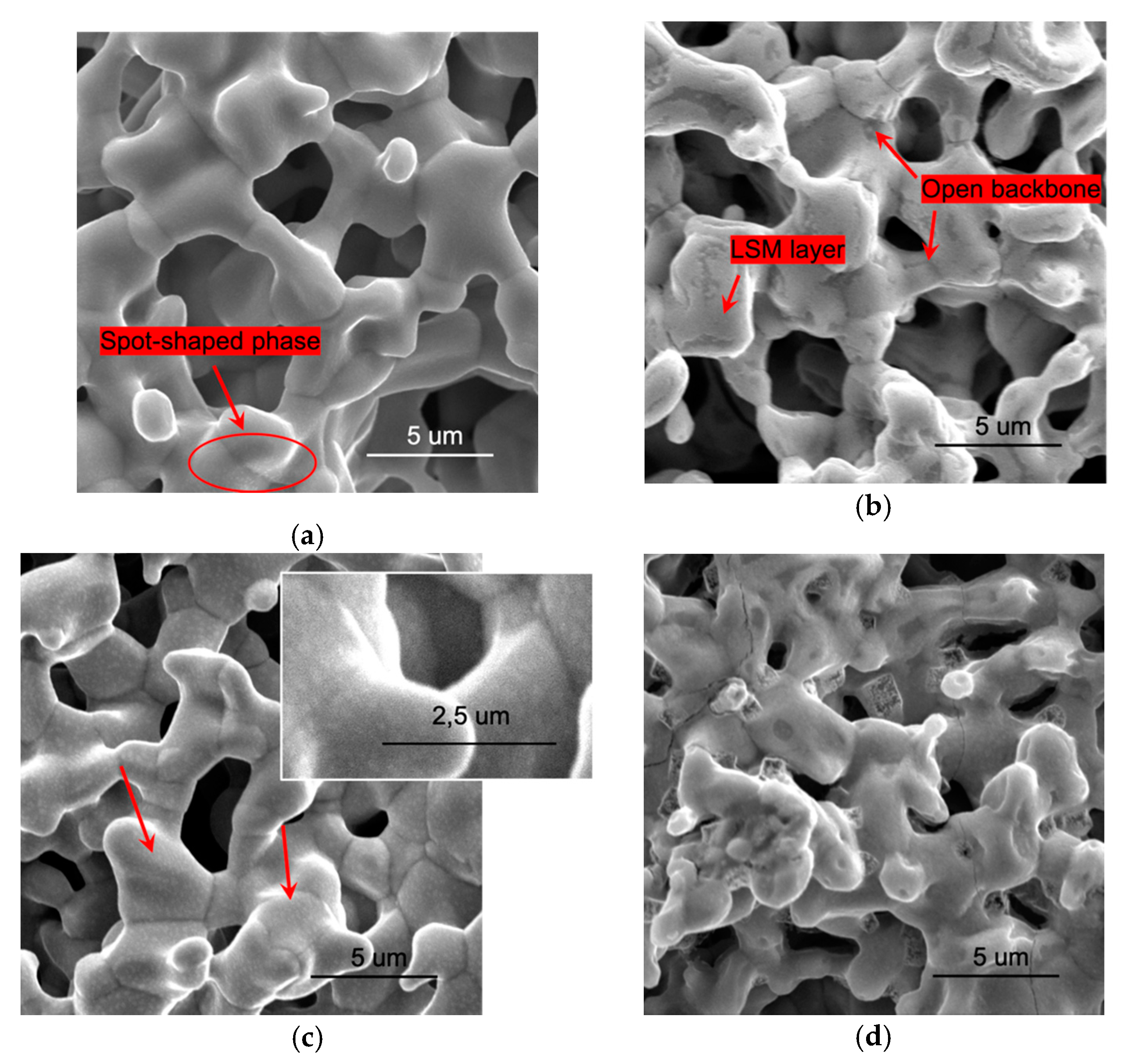
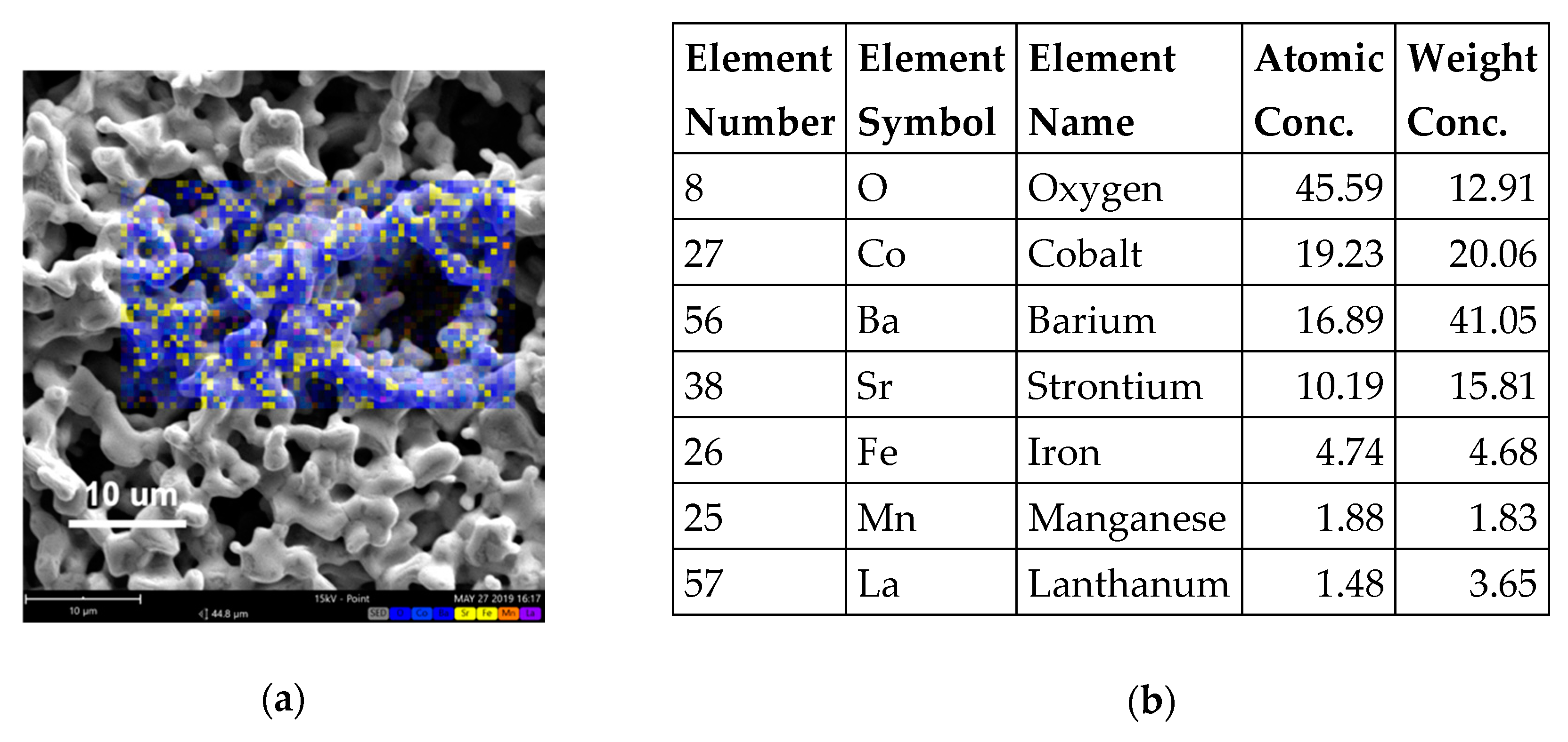
3.1. Microstructural

In Figure 1, the surface SEM images of the pristine BSCF and of the 1.5 μL, 0.06 mol L−1 LSM-infiltrated electrode are reported, before and after the electrochemical characterization. In the following, the LSM-infiltrated BSCF will be named just LSM-BSCF electrode.
After the sintering process at 1100 °C, the electrodes showed a homogeneous structure, with open porosity and an appreciable coarsening of the grains, resulting in the formation of a good interconnected ceramic network (see Figure 1).
The comparison of images obtained before (Figure 1a,b) and after the electrochemical testing (Figure 1c,d) shows that the porosity of structures was not affected by testing. By contrast, transformations were evident at the surface of both electrodes after the electrochemical investigation. On the surface of the blank BSCF electrode, a dot-shaped minor phase appeared (Figure 1c); likewise, in previous findings [31], it was supposed that this phase could result from the aggregation, during testing time between 475 and 650 °C, of the distributed phase already present on the BSCF starting electrode surface (Figure 1a, red arrow and oval). Concerning the infiltrated electrode, the LSM was distributed as a continuous and homogeneous layer at the beginning (Figure 1b), while, after the testing, several extended defects with sharp edges and micropores appeared (Figure 1d).
Figure 2 shows an SEM surface image of the as-prepared LSM-infiltrated layer and the corresponding atomic concentration obtained through a map elemental analysis. Further EDXS observations performed through the cross-section of the infiltrated electrode confirmed the penetration of the LSM layer up to the electrode/electrolyte interface.

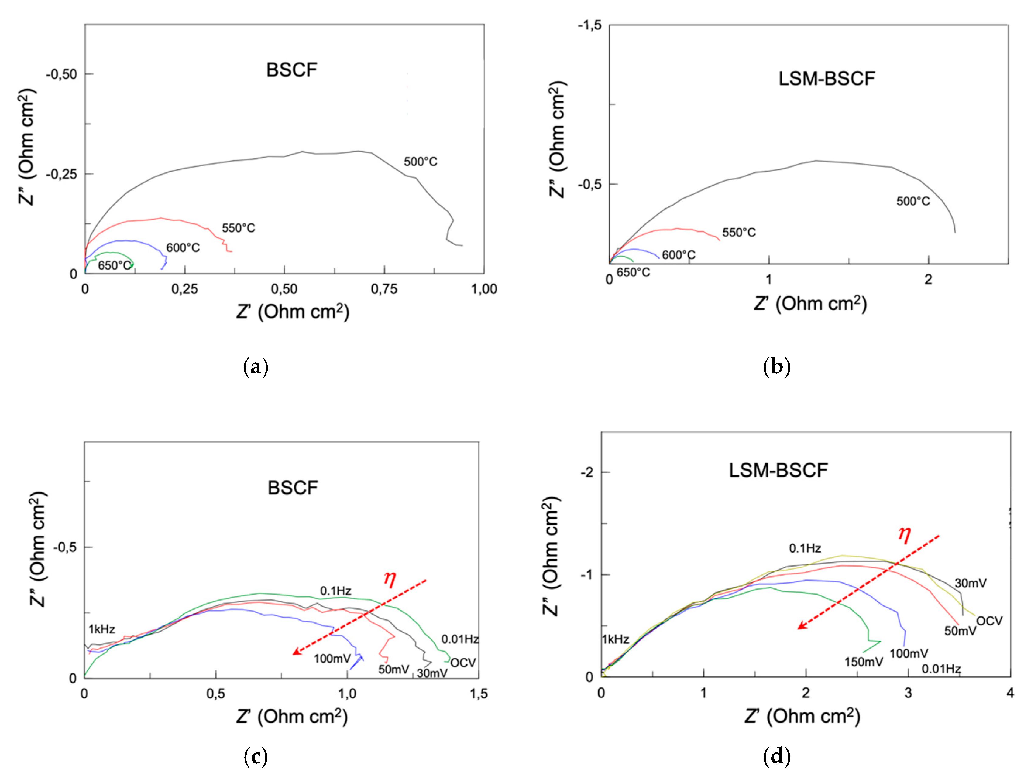
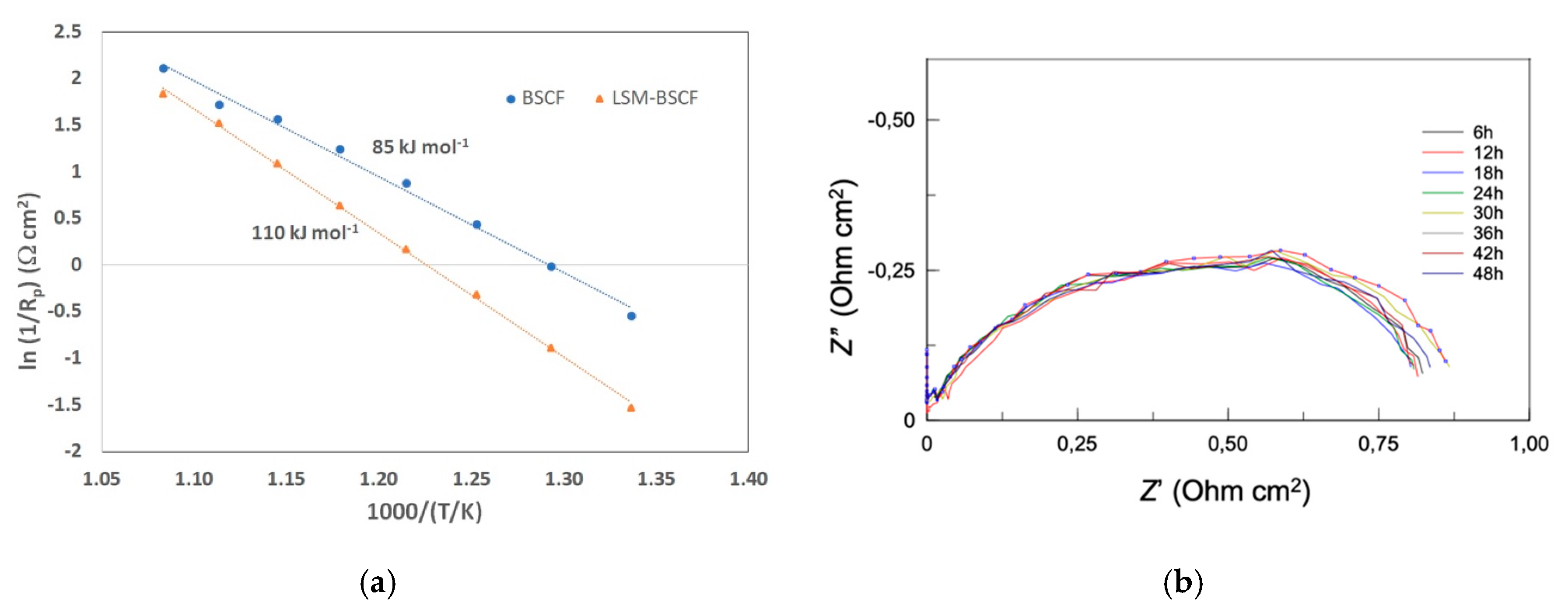
3.2. Electrochemical

Figure 3 reports an optical image (Figure 3a) of the partial side of SDC electrolyte with the slurry-coated WE (in the center) and RE (ring-shaped), while the geometry features of the three-electrode configuration are reported in Figure 3b, following the indications of [32,33], as aforementioned. The measurements were performed using an RE in order to have accurate control of the WE potential, especially when an overpotential was applied.
Impedance spectra were modeled through an equivalent circuit in order to obtain the different parameters, such as polarization resistance. The equivalent circuit consisted of a resistance (Re) in series with an inductance (L1) and two resistance/constant phase elements (R1/CPE1 and R2/CPE2) in series as shown by Figure 3c. The constant phase elements were chosen in view of their flexibility to model the circuits obtained in the different conditions of operations.
First, impedance measurements were carried out at OCV, then tests were run by applying an anodic overpotential, up to +0.2 V.
In Figure 4, impedance spectra of blank BSCF (Figure 4a) and LSM-BSCF (Figure 4b) are shown. It is evident that the values of polarization resistance (Rp), extracted as the difference between the low and high frequency intercepts with the real axis, are larger for the infiltrated electrodes than for pristine BSCF. At OCV and 650 °C, the value of the area specific resistance (ASR), as obtained by modeling, was 0.121 Ω cm2 for the blank electrode and 0.160 Ω cm2 for the infiltrated one. These results agree with other works, dealing with both blank and LSM-infiltrated electrodes [34,35,36]. The polarization resistance values obtained for the blank BSCF and LSM-BSCF infiltrated electrode were in contrast with previous findings obtained by the authors on LSM-infiltrated BSCF electrodes. In that case [31], the LSM infiltration had a positive effect in terms of Rp at OCV. The reason for this discrepancy is likely due to the different morphology of the LSM-infiltrated layer. In the previous work, we dealt with a nano-sized discrete layer, resulting in an increased electrode–gas surface exchange area and consequent improved electrode activity; in this study, a continuous LSM layer was obtained, whose exchange properties with the gas phase are very different from those of the nano-distributed one.
Considering the effect of anodic overpotential (Figure 4c,d), it had a positive effect in terms of Rp values, both in case of blank and infiltrated samples. It was already found in previous study that cathodic overpotential had, on the contrary, a negative influence on the electrocatalytic performance of BSCF-based electrodes [17]. The positive effect of anodic overpotential was further confirmed through a sweep voltammetry measurement. Although not reported in the paper, the current density measured under anodic overpotential was slightly higher than that under cathodic overpotential, indicating a higher activity in anodic conditions (namely, when the electrode is involved as anode in the electrolysis mode of operation).
The presence of LSM did not improve the trend of impedance when η was increased. At the temperature of 475 °C, Rp at OCV was 4.43 Ω cm2 for LSM-BSCF, while it decreased until 1.72 Ω cm2 for the blank electrode. For the latter, an ASR decrease of 32% was observed under increasing anodic overpotential; the LSM-BSCF displayed a 24% decrease between OCV and +0.100 V, becoming 34.5% between OCV and +0.150 V. Unfortunately, beyond +0.1 and +0.15 V, the overpotential applied to blank and infiltrated electrodes, respectively, was destroyed, with the infiltrated one appearing more resistant.
In Figure 5, the inverse of polarisation resistance (1/Rp) is reported as a function of temperature. An Arrhenius-like behaviour allowed for obtaining the values of apparent activation energy (Ea) for both the systems: 85.3 and 110.6 kJ mol−1 for blank BSCF and LSM-BSCF, respectively. These activation energy values concern the activity during the dynamic equilibrium state at OCV. It has been proven in the literature that LSM activity drops under anodic conditions [37], and, actually, the impedance spectra extracted under anodic overpotential conditions confirm that the presence of the LSM hinders the activity of the electrode (see Figure 4c,d). Despite this detrimental effct due to LSM, the increase in the catalytic activity of the BSCF was confirmed when a net anodic current flowed through the cell. As observable in Figure 4d, the LSM hindering effect was not able to counterbalance the enhanced activity of BSCF. Moreover, the LSM-infiltrated layer resulted in a positive effect on the long-lasting performance of the SDC/LSM-BSCF system. In previous work, it was found that LSM contributed to maintaining the polarization stability of the BSCF electrode, likely because of a positive influence on the electrochemical potential gradient at the interface LSM/BSCF, with this stabilizing effect indeed also observed for LSCF-based and other electrodes [14,17].
An anodic load of 0.150 V was run for 48 h at 600 °C, and an impedance test was performed every 6 h. The result is shown in Figure 5. It is observed that the activity behavior, in terms of polarization resistance, was stable for the duration of the test. During the voltage load, a current of 14 mA cm2 was observed at 600 °C. This value should certainly be improved, but optimization of the electrode morphology and performance under different gas partial pressures will be the subject of further investigations.

4. Conclusions

In this study, blank BSCF and LSM-infiltrated BSCF electrodes are analyzed, in view to be used as possible anode electrodes in solid state electrolysis (SOEC) devices. Electrochemical impedance spectroscopy investigation, coupled with an aging test at +0.15 V current load, was performed on a three-electrode system with SDC20 electrolyte.
It was found that polarization resistance decreased in both systems when an increasing anodic current load was applied. The blank BSCF electrode showed lower resistance (Rp) than the infiltrated one; then, it appeared that LSM did not give the chance to improve performance. This is possibly due to the detrimental effect of the continuous LSM layer covering most of the BSCF backbone. An LSM nano-sized discrete layer could result in increasing the surface exchange area, without subtracting appreciable BSCF surface, and consequently making the gas–electrode activity faster. This was actually found out previously by the authors.
On the other hand, the LSM layer had a positive effect on the impedance stability, since no sign of degradation appeared in the first 48 h under a voltage load of +0.150 V. Performance degradation in the first 100 h of operation is one of the major problems to be faced in SOFC/SOEC devices, and LSM infiltration was demonstrated to be a promising approach in overcoming this issue. Further attempts must be carried out in order to find the optimized parameters for a nano-sized discrete layer of LSM to be deposited. Most importantly, it was confirmed that BSCF-based electrodes are very promising candidates to be used as oxygen electrodes in rSOC.

Author Contributions

Conceptualization, M.P.C., A.B., G.C. (Giacomo Cerisola) and R.B.; methodology, M.P.C., A.B., M.V. and S.P.; software, M.P.C., M.V., D.C. (Davide Clematis); formal analysis, M.P.C., X.M.d., D.C. (Davide Clematis) and D.C. (Davide Cademartori); investigation, X.M.d.; resources, M.P.C., G.C. (Giacomo Cerisola); S.P. and R.B.; data curation, M.P.C., X.M.d.; writing—original draft preparation, M.P.C., X.M.d., M.V. and D.C. (Davide Cademartori); writing—review and editing, M.P.C., S.P., M.V., X.M.d., D.C. (Davide Cademartori), D.C. (Davide Clematis), R.B., A.B., G.C. (Giacomo Cerisola), G.C. (Gilles Caboche); visualization, M.P.C. and X.M.d.; supervision, M.P.C.; funding acquisition, A.B., G.C. (Gilles Caboche), and G.C. (Giacomo Cerisola). All authors have read and agreed to the published version of the manuscript.

Funding

This research was funded in part by the Regional Council of Bourgogne Franche-Comté and the French National Center for Scientific Research (CNRS) Graduate School EIPHI (Contract ANR-17-EURE-0002) and through a visiting researcher position granted to M.P.C.

Acknowledgments

M. Paola Carpanese acknowledges the University of Genova for funding resources coming from FRA Fondi di Ricerca di Ateneo 2018.

Conflicts of Interest

The authors declare no conflict of interest.

References

  1. European Commission. A European Green Deal. Available online: https://ec.europa.eu/info/strategy/priorities-2019-2024/european-green-deal_en (accessed on 10 June 2020).
  2. Gupta, R.; Soini, M.C.; Patel, M.P.; Parra, D. Levelized cost of solar photovoltaics and wind supported by storage technologies to supply firm electricity. J. Energy Storage 2020, 27, 101027. [Google Scholar] [CrossRef]
  3. Zsiborács, H.; Hegedüsné Baranyai, N.; Vincze, A.; Zentkó, L.; Birkner, Z.; Kinga, M.; Pintér, G. Intermittent Renewable Energy Sources: The Role of Energy Storage in the European Power System of 2040. Electronics 2019, 8, 729. [Google Scholar] [CrossRef] [Green Version]
  4. Mogensen, M.B.; Chen, M.; Frandsen, H.L.; Graves, C.; Hansen, J.B.; Hansen, K.V.; Hauch, A.; Jacobsen, T.; Jensen, S.H.; Skafte, T.L.; et al. Reversible solid-oxide cells for clean and sustainable energy. Clean Energy 2019, 3, 175–201. [Google Scholar] [CrossRef]
  5. Venkataraman, V.; Pérez-Fortes, M.; Wang, L.; Hajimolana, Y.S.; Boigues-Muñoz, C.; Agostini, A.; McPhail, S.J.; Maréchal, F.; Van Herle, J.; Aravind, P.V. Reversible solid oxide systems for energy and chemical applications—Review & perspectives. J. Energy Storage 2019, 24, 100782. [Google Scholar]
  6. Perna, A.; Minutillo, M.; Jannelli, E. Designing and analyzing an electric energy storage system based on reversible solid oxide cells. Energy Convers. Manag. 2018, 159, 381–395. [Google Scholar] [CrossRef]
  7. Giarola, S.; Forte, O.; Lanzini, A.; Gandiglio, M.; Santarelli, M.; Hawkes, A. Techno-economic assessment of biogas-fed solid oxide fuel cell combined T heat and power system at industrial scale. Appl. Energy 2018, 211, 689–704. [Google Scholar] [CrossRef] [Green Version]
  8. Carpanese, M.P.; Panizza, M.; Viviani, M.; Mercadelli, E.; Sanson, A.; Barbucci, A. Study of reversible SOFC/SOEC based on a mixed anionic- protonic conductor. J. Appl. Electrochem. 2015, 45, 657–665. [Google Scholar] [CrossRef]
  9. Thorel, A.S.; Chesnaud, A.; Viviani, M.; Barbucci, A.; Presto, S.; Piccardo, P.; Ilhan, Z.; Vladikova, D.; Stynov, Z. IDEAL-cell, a high temperature innovative dual mEmbrAne fuel cell. ECS. Trans. 2009, 25, 753–762. [Google Scholar] [CrossRef] [Green Version]
  10. Gondolini, A.; Mercadelli, E.; Sangiorgi, A.; Sanson, A. Integration of Ni-GDC layer on a NiCrAl metal foam for SOFC application. J. Eur. Ceram. Soc. 2017, 37, 1023–1030. [Google Scholar] [CrossRef]
  11. Zheng, Y.; Wang, J.; Yu, B.; Zhang, W.; Chen, J.; Qiao, J.; Zhang, J. A review of high temperature co-electrolysis of H2O and CO2 to produce sustainable fuels using solid oxide electrolysis cells (SOECs): Advanced materials and technology. Chem. Soc. Rev. 2017, 46, 1427–1463. [Google Scholar] [CrossRef]
  12. Brauns, Z.; Turek, T. Alkaline Water Electrolysis Powered by Renewable Energy: A Review. Processes 2020, 8, 248. [Google Scholar] [CrossRef] [Green Version]
  13. Laguna-Bercero, M.A. Recent advances in high temperature electrolysis using solid oxide fuel cells: A review. J. Power Sources 2012, 203, 4–16. [Google Scholar] [CrossRef] [Green Version]
  14. Presto, S.; Artini, C.; Pani, M.; Carnasciali, M.M.; Massardo, S.; Viviani, M. Ionic conductivity and local structural features in Ce1−xSmxO2−x/2. Phys. Chem. Chem. Phys. 2018, 20, 28338–28345. [Google Scholar] [CrossRef]
  15. Chen, G.; Sun, W.; Luo, Y.; He, Y.; Zhang, X.; Zhu, B.; Li, W.; Liu, X.; Ding, Y.; Li, Y.; et al. Advanced Fuel Cell Based on New Nanocrystalline Structure Gd0.1Ce0.9O2 Electrolyte. ACS Appl. Mater. Interfaces 2019, 11, 10642–10650. [Google Scholar] [CrossRef]
  16. Jaiswal, N.; Tanwar, K.; Suman, R.; Kumar, D.; Upadhyay, S.; Parkash, O.; Uppadhya, S.; Parkash, O. A brief review on ceria based solid electrolytes for solid oxide fuel cells. J. Alloy. Compd. 2019, 781, 984–1005. [Google Scholar] [CrossRef]
  17. Singh, S.; Singh, P.; Viviani, M.; Presto, S. Dy doped SrTiO3: A promising anodic material in solid oxide fuel cells. Int. J. Hydrogen Energy 2018, 43, 19242–19249. [Google Scholar] [CrossRef]
  18. Clematis, D.; Barbucci, A.; Presto, S.; Viviani, M.; Carpanese, M.P. Electrocatalytic activity of perovskite-based cathodes for solid oxide fuel cells. Int. J. Hydrogen Energy 2019, 44, 6212–6222. [Google Scholar] [CrossRef]
  19. Luo, H.; Wang, H.; Chen, X.; Huang, D.; Zhou, M.; Ding, D. Cation deficiency tuning of LaCoO3 perovskite as bifunctional oxygen electrocatalysts. ChemCatChem 2020, 12, 2768–2775. [Google Scholar] [CrossRef]
  20. Carpanese, M.P.; Clematis, D.; Bertei, A.; Giuliano, A.; Sanson, A.; Mercadelli, E.; Nicolella, C.; Barbucci, A. Understanding the electrochemical behaviour of LSM-based SOFC cathodes. Part I—Experimental and electrochemical. Solid State Ion. 2017, 301, 106–115. [Google Scholar] [CrossRef]
  21. Niu, B.; Lu, C.; Yi, W.; Luo, S.; Li, X.; Zhong, X.; Zhao, X.; Xu, B. In-situ growth of nanoparticles-decorated double perovskite electrode materials for symmetrical solid oxide cells. Appl. Catal. B Environ. 2020, 270, 118842. [Google Scholar] [CrossRef]
  22. Presto, S.; Kumar, P.; Varma, S.; Viviani, M.; Singh, P. Electrical conductivity of NiMo–based double perovskites under SOFC anodic conditions. Int. J. Hydrogen Energy 2018, 43, 4528–4533. [Google Scholar] [CrossRef]
  23. Rath, M.K.; Lee, K. Superior electrochemical performance of non-precious Co-Ni-Mo alloy catalyst-impregnated Sr2FeMoO6-δ as an electrode material for symmetric solid oxide fuel cells. Electrochim. Acta 2016, 212, 678–685. [Google Scholar] [CrossRef]
  24. Sharma, R.K.; Burriel, M.; Dessemond, L.; Bassat, J.-M.; Djurado, E. Lan+1NinO3n+1 (n = 2 and 3) phases and composites for solid oxide fuel cell cathodes: Facile synthesis and electrochemical properties. J. Power Sources 2016, 325, 337–345. [Google Scholar] [CrossRef]
  25. Arias-Serrano, B.I.; Kravchenko, E.; Zakharchuk, K.; Grins, J.; Svensson, G.; Pankov, V.; Yaremchenko, A. Oxygen-Deficient Nd0.8Sr1.2Ni0.8M0.2O4-δ (M = Ni, Co, Fe) Nickelates as Oxygen Electrode Materials for SOFC/SOEC. ECS Trans. 2019, 91, 2387–2397. [Google Scholar] [CrossRef]
  26. Wang, J.; Zhou, J.; Yang, J.; Zong, Z.; Fu, L.; Lian, Z.; Zhang, X.; Wang, X.; Chen, C.; Ma, W.; et al. Nanoscale architecture of (La0.6Sr1.4)0.95Mn0.9B0.1O4 (B = Co, Ni, Cu) Ruddlesden—Popper oxides as efficient and durable catalysts for symmetrical solid oxide fuel cells. Renew. Energy 2020, 157, 840–850. [Google Scholar] [CrossRef]
  27. Khoshkalam, M.; Tripković, Ð.; Tong, X.; Faghihi-Sani, M.A.; Chen, M.; Vang Hendriksen, P. Improving oxygen incorporation rate on (La0.6Sr0.4)0.98FeO3-δ via Pr2Ni1-xCuxO4+δ surface decoration. J. Power Sources 2020, 457, 228035. [Google Scholar] [CrossRef]
  28. Ding, D.; Li, X.; Lai, S.Y.; Gerdes, K.; Liu, M. Enhancing SOFC cathode performance by surface modification through infiltration. Energy Environ. Sci. 2014, 7, 552–575. [Google Scholar] [CrossRef]
  29. Jiang, S.P. A review of wet impregnation—An alternative method for the fabrication of high performance and nano-structured electrodes of solid oxide fuel cells. Mat. Sci. Eng. A 2006, 418, 199–210. [Google Scholar] [CrossRef]
  30. Aguadero, A.; Pérez-Coll, D.; Alonso, J.A.; Skinner, S.J.; Kilner, J. A New family of Mo-Dioped SrCoO3-δ Perovskites for Application in Reversible Solid State Electrochemical Cells. Chem. Mater. 2012, 24, 2655–2663. [Google Scholar] [CrossRef]
  31. Giuliano, A.; Carpanese, M.P.; Clematis, D.; Boaro, M.; Pappacena, A.; Deganello, F.; Liotta, L.F.; Barbucci, A. Infiltration, Overpotential and Ageing Effects on Cathodes for Solid Oxide Fuel Cells: La0.6Sr0.4Co0.2Fe0.8O3-δ versus Ba0.5Sr0.5Co0.8Fe0.2O3-δ. J. Electrochem. Soc. 2017, 164, F3114–F3122. [Google Scholar] [CrossRef]
  32. Winkler, J.; Hendriksen, P.V.; Bonanos, N.; Mogensen, M. Geometric requirements of solid electrolyte cells with a reference electrode. J. Electrochem. Soc. 1998, 145, 1184–1192. [Google Scholar] [CrossRef]
  33. Carpanese, M.P.; Giuliano, A.; Panizza, M.; Mercadelli, E.; Sanson, A.; Gondolini, A.; Bertei, A.; Sanson, A.; Gondolini, A.; Bertei, A. Experimental Approach for the study of SOFC cathodes. Bulg. Chem. Commun. 2016, 48, 23–29. [Google Scholar]
  34. Meng, L.; Wang, F.; Wang, A.; Pu, J.; Chi, B.; Li, J. High performance La0.8Sr0.2MnO3-coated Ba0.5Sr0.5Co0.8Fe0.2O3 cathode prepared by a novel solid-solution method for intermediate temperature solid oxide fuel cells. Chin. J. Catal. 2014, 35, 38–42. [Google Scholar] [CrossRef]
  35. Deganello, F.; Liotta, L.F.; Marcì, G.; Fabbri, E.; Traversa, E. Strontium and iron-doped barium cobaltite prepared by solution combustion synthesis: Exploring a mixed-fuel approach for tailored intermediate temperature solid oxide fuel cell cathode materials. Mater. Renew. Sustain. Energy 2013, 2, 8. [Google Scholar] [CrossRef] [Green Version]
  36. Yang, X.; Li, R.; Yang, Y.; Wen, G.; Tian, D.; Lu, X.; Ding, Y.; Chen, Y.; Lin, B. Improving stability and electrochemical performance of Ba0.5Sr0.5Co0.2Fe0.8O3-δ electrode for symmetrical solid oxide fuel cells by Mo doping. J. Alloy. Compd. 2020, 831, 154711. [Google Scholar] [CrossRef]
  37. Chen, X.J.; Khor, K.A.; Chan, S.H. Electrochemical behavior of La(Sr)MnO3 electrode under cathodic and anodic polarization. Solid State Ion. 2004, 167, 379–387. [Google Scholar] [CrossRef]
Figure 1. Surface SEM images of Ba0.5Sr0.5Co0.8Fe0.2O3-δ (BSCF) (a,c) and of LSM-BSCF (b,d) electrodes before (a,b) and after (c,d) the electrochemical testing. Inset in (c) shows an improved view of the spot-shaped phase. BSCF backbones were sintered at 1100 °C for 1 h.
Energies 13 03659 g001
Figure 2. SEM-EDXS of LSM-BSCF infiltrated electrodes (before testing). Surface SEM image (a) with corresponding atomic concentration obtained through a map elemental analysis (b).
Energies 13 03659 g002
Figure 3. Image and scheme of the cell used for electrochemical investigation. Working electrode (WE) and reference electrode (RE) on the SDC20 electrolyte (a); drawing of the three-electrode cell configuration (b). In (c) the equivalent circuit used to model impedance spectra is shown: inductance, L1; electrolyte resistance, Re; resistance/constant phase element, R1/CPE1 and R2/CPE2, at high and low frequency, respectively, of the electrode-related arch.
Energies 13 03659 g003
Figure 4. Impedance spectra at open circuit voltage (OCV) and under anodic overpotential (η up to +0.150 V). (a) OCV for blank BSCF; (b) OCV for infiltrated LSM-BSCF electrode; (c) with η for blank BSCF; (d) with η for LSM-BSCF infiltrated electrodes. Temperature conditions for (a,b): between 500 and 650 °C; for (c,d): 475 °C. In every case, SDC20 constitutes the electrolyte support. Measurements were performed in three-electrode configuration, using the ring-shaped RE.
Energies 13 03659 g004
Figure 5. (a) Trend of the inverse of polarization resistance (Rp) vs temperature, for blank BSCF and LSM-infiltrated BSCF. The values shown are the apparent activation energy from the linear regression; (b) impedance spectra obtained for the LSM-BSCF electrode every 6 h, at OCV, during the anodic current load of +0.150 V for 48 h at 600 °C.
Energies 13 03659 g005
Table 1. Composition of La0.8Sr0.2MnO3-δ-infiltrated layer.
La(NO3)2·2H2OSr(NO3)2Mn(NO3)3· xH2OGlycine PVP
10.477 g0.622 g7.289 g2.468 g 11.158 g 2
1 1/4 of the total molar amount of starting nitrates; 2 0.05 wt.% of La0.8Sr0.2MnO3 (LSM) amount.

