Article

Improved Analysis on the Fin Reliability of a Plate Fin Heat Exchanger for Usage in LNG Applications

by
Mustansar Hayat Saggu
1,
Nadeem Ahmed Sheikh
1,
Usama Muhamad Niazi
2,
Muhammad Irfan
3,
Adam Glowacz
4 and
Stanislaw Legutko
5,*
1
Department of Mechanical Engineering, International Islamic University, Islamabad 44000, Pakistan
2
Mechanical Engineering Department, Universiti Teknologi PETRONAS, Seri Iskandar 32610, Perak, Malaysia
3
Electrical Engineering Department, College of Engineering, Najran University, Najran 61441, Saudi Arabia
4
Department of Automatic, Control and Robotics, AGH University of Science and Technology, 30-059 Kraków, Poland
5
Faculty of Mechanical Engineering and Management, Poznan University of Technology, 3 Piotrowo Street, 60-965 Poznan, Poland
*
Author to whom correspondence should be addressed.
Energies 2020, 13(14), 3624; https://doi.org/10.3390/en13143624
Submission received: 5 June 2020 / Revised: 5 July 2020 / Accepted: 10 July 2020 / Published: 14 July 2020
(This article belongs to the Special Issue Energy Efficiency for IoT Systems)

Abstract

:
A plate fin heat exchanger (PFHE) is a critical part of the cryogenic industry. A plate fin heat exchanger has many applications, but it is commonly used in the liquefied natural gas (LNG) industry for the gasification/liquefaction process. During this gasification to the liquefaction process, there is a large temperature gradient. Due to this large temperature gradient, stresses are produced that directly influence the braze joint of PFHE. Significant work has been carried out on heat transfer and the flow enhancement of PFHE; however, little attention has been paid to structural stability and stresses produced in these brazed joints. Due to these stresses, leakages in PFHE are observed, mostly in braze joints. In the current study, standard fin design is analyzed. In addition, the structural stability of brazed joints under standard conditions is also tested. Two techniques are used here to analyze fins, using the finite element method (FEM), first by examining the whole fin brazed joint on the basis of experimentally calculated yield strength and second by dividing the braze seam into three sections and defining individual strength for each section of the seam to find stress magnitude on the basis of heat-affected zones. Moreover, by using two different techniques to analyze brazed joints, the stresses in the lower face of the brazed joint were increased by 13% and decreased by 18% in the upper face using different zone techniques as compared to standard full braze seam analysis. It can be concluded that different zone techniques are better in predicting stresses as compared to simple full braze seam analysis using the finite element method since stresses along the lower face are more critical.

Graphical Abstract

1. Introduction

Heat exchangers are a key component of industry and play a critical role in the smooth running of industry. Different types and sizes of heat exchangers are available for the diverse requirements of industry. The plate fin heat exchanger (PFHE) is one variety of heat exchangers mainly used in the cryogenic industry [1]. They have different applications but are mostly used in the liquefied natural gas (LNG) industry, as LNG is one of the key sources of clean energy and has low CO2 emissions [2]. The main feature of PFHEs is their large surface area with respect to their total volume. Commonly, plain fins are used in the PFHE assembly due to their ease of manufacturing and symmetric heat transfer in all direction [3]. New designs of PFHEs are introduced by designers and manufacturers to further increase their surface area and heat transfer and flow properties [4]. Generally, in natural gas (NG) to LNG conversion plants, PFHEs work between a normal temperature of 298.5 °K and 155 °K, which is quite a large temperature gradient. Therefore, for this conversion, a large amount of energy is required to exchange heat between the NG and the mix refrigerant (MR). Moreover, this large temperature gradient in the conversion/transportation of LNG brings stresses, which consequently cause leakages in the system. The stresses produced in the LNG system are a combination of normal and shear stresses. Hence, from a safety point of view and for the proper conservation of energy, they must be on time before a large disaster occurs due to the inflammable nature of LNG.
In past studies, heat transfer and flow parameters were substantially analyzed, but structural stability was greatly neglected [5,6]. Earlier researchers considered the PFHE as a porous medium to study its flow characteristics in a dual flow heat exchanger. They concluded that by changing dynamic viscosities, flow characteristics could be improved, but structural stability was neglected [5]. In a study performed by Ligterink et al. [6], moisture was introduced inside the PFHE to improve its heat transfer capability without considering its effect on the strength of the heat exchanger. Similarly, another group of researchers analyzed three wavy fin types for flow enhancement in PFHEs and determined that the winged wavy fin was better than typical wavy fin at the lowest Reynolds number and had the highest waviness aspect ratio without considering structural reliability [7]. Serrated fins were analyzed by a group of researchers by employing computational fluid dynamics (CFD) tools, and it was concluded that keen-edge geometries and fin-brazed joints are the primary cause of failure during the flow of gases/fluids in heat exchangers [8].
Operational and structural variations are also studied by researchers to enhance the strength of PFHE against stress concentration at brazed joints [9,10]. Similarly, optimization techniques are also used by some researchers to analyze PFHEs where the number of plates was minimized using screening techniques to explain the problem without considering the rigidity of structure [11]. Another group of researchers analyzed three configurations of PFHE—corrugated/vortex-generator plate-fin (CVGPF), corrugated plate-fin (CPF), and vortex-generator plate-fin (VGPF) configurations for thermal efficiency. They concluded that, under the same operating and geometrical conditions, the CVGPF channel showed the best thermal-hydraulic performance [12]. In another study, plain and perforated fins were analyzed, and it was concluded that, in perforated fins, increased heat transfer was observed with an overall pressure drop as compared to plain fin [13]. Recently, Peng et al. [14] investigated the inlet design to PFHE on the basis of improved heat transfer; however, its effect on structure stability was not considered.
The effect of baffle plates on flow parameters of PFHEs was analyzed by a group of researchers without considering the flow variation effect on stress distribution [15]. Some researchers analyzed the use of a PFHE with variable displacement pumps [16]. Their study concluded that by increasing the initial temperature of the fluid and the quantity, the heat transfer could be improved. A trapezoidal fin design was introduced by Onah et al. [17] to improve heat transfer effectiveness without analyzing their stability as compared to other fin types. Nagarajan et al. [18] analyzed nine different fin designs and flow parameters of PFHEs at high temperatures experimentally and by employing CFD. A good agreement was found between CFD and experimental results, but without considering structural integrity.
Generally, PFHEs are analyzed using the finite element method (FEM) because of cryogenic conditions, and experimental validation is generally carried out at room temperature [19]. Considering the efforts put into investigating different parameters, a PFHE is still prone to leakages, especially in brazed joints [20]. These brazed joint consist of the following three zones: interface on both sides and filler material at the center of heat-affected zone (HAZ) [21]. In these zones, there are variable strengths of different zones, and ductile failure generally happens in aluminum braze joints [22,23]. It is experimentally verified that there is a decrease in strength with an increase in elongation of the joint from the center of joint [24]. These zones are developed due to different heat inputs at different regions, which cannot be entirely controlled [25]. In the past, FEM was used to solve this type of analysis by employing mesh sensitivity analysis, but coupled thermal structural analysis is scare [26]. Now, with the advancement in FEM techniques, different three dimensional symmetric structural can be analyzed with more points distribution without facing any blind points that are observed in experimental method [27]. Moreover, due to structural symmetry, FEM can be best used for analyzing stresses in PFHEs [28]. By the introduction of new variation in the design of a fin, there is a chance of maldistribution in flow, mainly due to changes in inlet and outlet fluid properties, which can consequently cause stresses [29]. Recently, Mustansar et al. [30] analyzed the brazed joints of PFHEs using FEM and taking into consideration the actual yield strength; however, HAZ was not considered. In that analysis, three different fin configurations were analyzed—namely, plain, wavy, and compound fin configurations. After FEM and experimental analysis, it was found that the compound configuration was most vulnerable to leakages, followed by the wavy fin configuration, and the safest of all was the plain fin configuration. In addition, shear stress is critical for wavy fin brazed joints, whereas plain fins were at more risk to normal stress.
By keeping in consideration the limitations of past studies, the strength of PFHE fins are analyzed with two different FEM techniques. Furthermore, the actual brazed strength of the material is utilized instead of base material strength, which was commonly used by earlier researchers through standard experimental validation [31]. The primary contribution of this study is that the braze joint were analyzed as a single identity, but in current research, the braze joint is divided into three zones based on different yield strength calculated from experiment. By dividing the braze seam into different zones, the results from earlier techniques in critical areas are validated and improved. Second, the improved factor of safety (FOS) and margin of safety (MOS) based on three different zone criteria are calculated for critical stress areas. Third, earlier researchers used base material strength, whereas in this case, brazed strength from an experiment is used in both techniques, thus analyzing the braze seam as a single unit with different zones.

2. Materials and Methods

A PFHE is a key component in many industrial applications and has a symmetric design structure. The main assembly of a PFHE is shown in Figure 1. Both MR and NG flow in the counterflow direction.
In the current study, the portion of the PFHE employed for analysis is presented in Figure 2. Detailed parts of a PFHE are shown below. In this analysis, a small length (l) of plain fin is analyzed because of the symmetry of the PFHE. In this analysis, the MR side is analyzed at the entrance. This is because typical structural/thermal stress coupling takes place at the entrance, so from here, we can measure the maximum stresses produced in the brazed joint.
Two methods are used to analyze a PFHE. In the first method, the PFHE braze joint is analyzed entirely as one unit, and in the second method, three zones are defined (sub-faces) in the brazing seam. Stresses are calculated for a plain fin. Both methods are described in Figure 3.
To investigate the structural stability of plain fin designs, ANSYS 18 software (ANSYS 13, Canonsburg, PA, US) is used. In ANSYS software, actual working conditions are computer-generated. The analysis is based on the Von Mises theory. Equivalent stress is measured using the Von Mises theory [32] as
δ v = 1 2 [ ( δ 1 δ 2 ) 2 + ( δ 2 δ 3 ) 2 + ( δ 3 δ 1 ) 2 ]
A PFHE is safe from leakages when the equivalent stress is less than the yield strength.
δ v δ y e i l d
In the first method, post braze joint yield strength was used to make the analysis more realistic. In the second method, brazing seam is divided into three zones for further improvement in analysis method. Upper and lower zones have interface yield strength, whereas the center zone has the yield strength of the filler material, as shown in Figure 4. When experimental validation between Al 3003 and Al 4004 was carried out, the samples that were broken from the joint end had lower strength as compared to the yield strength of the filler material that was earlier used. This phenomenon is shown in Figure 4, which depends on variable heat input and can occur at any stage of brazing [30].
Once the techniques used in this analysis are defined, normal, shear, and equivalent stresses are calculated for a plain fin during this analysis. The plain fin is analyzed under actual structural/thermal conditions for LNG application. In this analysis, first, normal and shear stresses are calculated for each case using ANSYS 18. Later, these stresses are used to calculate the factor of safety (FOS) for plain fin. FOS is the ratio between applied load and strength of structure [33] and is defined as
Factor   of   Safety = n = δ s L
In past studies, the base material strengths of aluminum were used, but in this analysis, the actual brazed strength of aluminum 4004 with aluminum 3003 is used. The actual brazed strength was lower than the base material strength, which was used by earlier researchers [34]. Hence, by using actual brazed strength, which is lower than base material strength, fins can be more stable, and the PFHE will be more reliable. Importantly, the FOS defined using this strength will be more realistic. The reduction in strength of brazed joints is due to invariabilities in the brazing process [9,35]. On the basis of this strength, FOS is defined for a plain fin.
After defining the post braze strength used in this analysis of PFHE brazed joints, the properties used for NG and MR are discussed here. NG and MR flow in opposite direction in the PFHE. NG enters the PFHE at 210 °K and leaves in liquified form at a temperature of 150 °K by heat exchange with MR, while MR leaves the PFHE in vaporized form at a temperature of 215 °K from initial temperature of 155 °K [20]. The pressure of NG and MR is 7.1 MPa and 0.4 MPa, respectively. The heat transfer coefficient for MR is hMR = 1.0 kW/ (m2 K) and for NG is hNG = 1.5 kW/ (m2 K). These heat transfer coefficients are valid only for LNG applications, and the temperature between the two steams should not be more than 10 °C. Heat transfer takes place by conduction through the PFHE assembly and due to the convection phenomenon (from the gas/liquid to the fin) [10,20]. For a critically stressed point location, ANSYS software is employed to the PFHE brazed assembly. This analysis is based on structural thermal combination.

ANSYS Software for Analysis

For PFHE analysis in ANSYS, mainly tetrahedral, pyramid, triangular prism, and hexahedral elements are used for three-dimensional analysis, but in the current study, hexahedral element was used. The primary reason of using hexahedral elements is their high convergence rate as compared to other elements [9,36]. Significant reduction in central processing unit (CPU) memory use is observed when hexahedral elements are used. Three variable element sizes are used—1 mm, 0.5 mm, and 0.032 mm—which resulted in 144,295, 137,600, and 275,481 cells, respectively. At an element size of 0.032 mm with 275,481 cells, mesh independency was obtained and is employed for the present study.
Mesh cells are significantly reduced because, in this analysis, we are analyzing a single fin instead of a two-fin configuration. In this analysis, the transition ratio and growth rate are 0.272 and 1.2, respectively. Number of iterations before solution converge are 14. Heat transfer and temperature was employed during thermal analysis followed by pressure in structural analysis. Additionally, the PFHE original dimension with a boundary condition is applied. Due to sliding frames below the PFHE assembly, the PFHE can move independently; for this reason, the external load on the fin can be ignored, and a single fin can be analyzed independently [37]. Due to the symmetric structure of the PFHE, the layer number is not considered. NG and MR are in counter flow direction, as previously shown in Figure 1. As analysis is based on critical stress points detection, base material Al 3003 and Al 4004 are assumed to deform elastically. Table 1 presents the dimensions of fins used in this study.
In this analysis, Al 4004 is the filler material, whereas Al 3003 is the base material. In past studies, mostly pre-brazed strengths were used to analyze stress concentration points in a PFHE, whereas in the current study, post-brazed strength is used, which is lower than the base material strength [9,10,19]. By using post brazed strength, structural reliability of fins can be increased. The working temperature range is between 145~305 °K. Properties for Al 3003 like the Poisson ratio (0.33), specific heat (962 J/kg K), density (2740 kg/m3), and thermal conductivity (159 W/m K) will remain constant within this range of temperature, whereas the modulus of elasticity and co-efficient of thermal expansion will vary. Similarly for Al 4004, Poisson’s ratio (0.35), specific heat (864 J/kg K), density (2710 kg/m3), and thermal conductivity (155 W/m K) are constant, while the modulus of elasticity and the co-efficient of thermal expansion will change, as shown in Table 2 [19].

3. Results and Discussions

In this section, equivalent, normal, and shear stresses with FOS will be discussed for a plain fin brazed seam. The stress magnitudes produced in fins are important in understanding structural stability. Stresses along every face will be concluded with the reason of increase/decrease in stress for a specific fin brazed seam. Second, equivalent, normal, and shear stress using two different techniques for plain fin are also presented in following section. With these two techniques, we will be able to describe a modified FOS for the plain fin brazed seam.

3.1. Stress for Brazed Joint in Upper/Lower Brazed Seam of PFHE Using Earlier Yield Criteria and Modified Different Zones Strength Criteria for a Plain Fin

First, global stresses are presented, which shows that critical stresses in braze joints are observed on the edges of the brazed joints. So, for the reliability of the PFHE, these stresses need to be calculated locally. These global stresses consist of equivalent, normal, and shear stress, as shown in Figure 5a–c, respectively.
Later, local stresses in the upper face of the brazing seam are calculated as presented in Figure 6. These stresses play a critical role in the stability of the PFHE.
For simplicity and the clarity of local stresses in braze joint, it is divided into two faces—the upper and lower face of the brazed joints, as shown in Figure 5. Yield strength of filler material is taken as 112 MPa for tension/compression (aluminum strength in compression/tension is generally equal) and 62 MPa for shear strength (which is 55% of the yield strength) [40].
First, this analysis is performed with brazed seam as single entity. Detail of the analysis is shown in Figure 6. Stresses having maximum magnitudes are calculated using the braze seam as single unit. It can be seen in Figure 6 that equivalent stress has a maximum magnitude of 52 MPa for a plain fin braze seam, whereas normal x-axis stress has a maximum magnitude of 40 MPa. Similarly, y-axis stress magnitude is 15 MPa in the upper face of the braze seam. Z-axis stress is 3 MPa and is the lowest of all normal stresses. Shear stresses calculated here are x-y and y-z, respectively, having maximum magnitudes of 3 MPa and 6 MPa.
It can be perceived from Figure 6 that the most critical stress for the plain fin is equivalent stress; thus, Figure 7 is plotted to analyze this situation. The plain fin is analyzed using two different techniques—the fin braze seam as a single unit and the brazing seam having three different zones based on yield strength calculated from the experiment. For reliability and the simplicity of analysis of the fin brazed seam, only critical stresses calculated from the method of the brazed seam as a single unit are compared using the different zones technique. Moreover, the FOS along this direction is quite high in cases of normal and shear stress; hence, for ease of analysis, only equivalent stress is compared using the two methods, as shown in Figure 7. It can be seen that there is sudden rise in stresses up to 51 MPa due to the sharp end of brazed seam, followed by a slow descent of stresses up to 13 MPa due to the curvature in the brazed seam. The stresses remain constant until the distance of 1.35 mm due to the uniform geometry of the brazed seam. Later, the stresses increased sharply and reached a maximum stress of 52 MPa, followed by a sharp decline. It is significant to note that, by defining three different zones, stresses in the upper face of the braze seam are decreased by 18% as compared to investigating the braze seam as single unit due to the variable strength of different zones.
After calculating stresses in the upper plain fin brazed seam, equivalent, normal, and shear stresses in the lower face of braze seam are estimated and are presented in Figure 8. It can be seen that, in the lower portion of braze seam, stresses act differently than in the upper braze seam of the PFHE. Equivalent stress has a maximum magnitude of 86 MPa in the lower face of the braze seam, where x-axis stress has a maximum magnitude of 20 MPa in this region. Y-axis stress, being critical, has maximum magnitude of 82 MPa. Similarly, shear stresses for x-y and y-z axes have magnitudes of 2 MPa and 15 MPa, respectively.
Notably along the lower face of the seam, equivalent and normal y-axis stresses are critical. Therefore, these two stresses are calculated along the lower face of the brazed seam using two methods, i.e., the full braze seam and the three-zones braze seam (presented in Figure 9). It is important to note that the trend followed by stresses along the lower face of seam is totally different from the upper seam of the brazed joint (as shown in Figure 7). Overall, the stresses followed a curved pattern along the lower half of the brazed seam, where the stresses are initially very high due to the edge contact of the fin with the brazed seam, followed by a smooth decrease until the middle that is primarily due to uniformity of brazed seam, and the stresses again increased to 95 MPa due to the sharp edge contact at the other end. More importantly, it can be seen that the equivalent stress for the plain fin brazed seam is increased by 13%, and the normal y-axis stress is increased by 18% when using the different zones method as compared to the single brazed unit method. This is due to the variable properties of different zones, and the lower braze seam strength (when using different zones) is less than the average strength of the full braze seam.
The factor of safety is critical in any mechanical structure design. Therefore, FOS is analyzed and presented in Table 3. Initially, FOS is calculated using the previous technique of the full braze seam, which is then verified and improved using the different zones technique. By using the different zones technique, a modified FOS is presented. FOS is improved in the case of equivalent stress along the upper face of the plain fin brazed seam. Stresses due to the different zones technique are decreased in the upper face of the fin, and hence, FOS is increased for the plain fin.
After analyzing the FOS along the upper face of braze seam, modified FOS is discussed using the different zones technique for the lower face of the brazed seam as shown in Table 4. It can be seen that the FOS along lower face is critical for the plain fin brazed seam, specifically in the case of normal y-axis and equivalent stress. Importantly, using the modified zones technique, equivalent and normal y-axis stresses have increased further, due to which the FOS is decreased, but it still remains within yield limits. Therefore, the different zones technique gives better insight into the stresses in the brazed joints.

3.2. Vertical Strength of Brazed Joint Using Normal Yield Criteria and Different Zones Criteria

In this section, stresses are calculated in the vertical direction for the plain fin brazed seam. Global stresses for the complete PFHE assembly are shown below in Figure 10. It can be seen that, close to upper braze joint, there are critical equivalent stresses that need to be analyzed. Hence, in this region, local stresses are analyzed in the vertical direction of the brazed joint and are presented in Figure 11.
In the next section, the plain fin brazed seam is discussed. Equivalent, normal and shear stress is calculated along all three principal axes, and critical stresses are analyzed using the full braze seam and different zones techniques.
Local stresses calculated are based on the global stress concentration area, which is shown in Figure 10 and Figure 11. First, in case of a plain fin brazed seam equivalent, normal and shear stresses are calculated. Importantly, equivalent stress is high, and its magnitude is 70 MPa, whereas normal stresses are within a safe range, having magnitudes of 35 MPa and 30 MPa for x-axis and y-axis stresses, respectively. Likewise, for normal stress, shear stress is also structurally safe for the PFHE, with a maximum magnitude of 28 MPa for y-z and 5 MPa for x-y stresses.
In this case, most critical stress is equivalent stress, which need to be analyzed for safety against stresses. The different zones method is used for this purpose, as shown in Figure 12. It can be seen that the stress phenomenon is quite different and critical where stresses are low at the start due to higher fin strength as compared to brazed joint, but as the fin/braze intersection point is reached, there is a significant increase in stress, with a maximum recorded magnitude of 72 MPa. After that, there is a sharp decrease in stresses, primarily due to braze curved geometry. It is important to note that equivalent stress is increased by 5% when using the different zones technique as compared to the full brazed seam.
Finally, FOS is calculated using the full braze seam and then compared with modified FOS as presented in Table 5. It is important to note that, due to the increase in stress, the FOS for equivalent stress is more critical along this direction. Second, due to the different zones technique, the critical stresses, i.e., equivalent stresses in vertical, is increased by 5%, which shows that more safety is required in the plain fin braze seam along this direction (and the reliability of the technique).

3.3. Modified Margin of Safety by Using Different Zones Criteria

In the last section, structural stability of different brazed seams of fins in term of normal and shear stress is analyzed. To reconfirm our results, we used interaction equations, which are primarily used for brazed joint analysis. In the FOS method. individual strength is analyzed, but in case of the interaction equation, cumulative damage by both shear and normal stresses are analyzed by a single equation [42]. The interaction equation used here for evaluating the fin brazed seam is
MOS = ( 1 / R δ 2 + R τ 2 ) 1
R δ = δ δ o
and
R τ = δ τ δ τ o
Failure due to combined loading can be analyzed by the above equations. Modified MOS is defined because stresses are changed when using different zones techniques, as discussed in previous section for critical stresses. MOS using full braze seam and modified MOS when using the different zones technique are shown in Table 6 for a plain fin braze seam cases along x-y paths.
From Table 6, it can be concluded that using the different zones technique, stress magnitudes are varied for braze joints, and the MOS is therefore changed. Stresses have increased when using the different zones technique in the lower face of the brazed seam and decreased in the upper face of the braze seam as compared to the results of the braze seam as one unit. Y-axis stress magnitudes have increased, which caused a decrease in MOS along the lower face of the braze seam.

4. Conclusions

In the above study, the plain fins braze seam is analyzed using ANSYS and experiment for stress analysis. After analyzing the above case, the major findings are as follows:
(a)
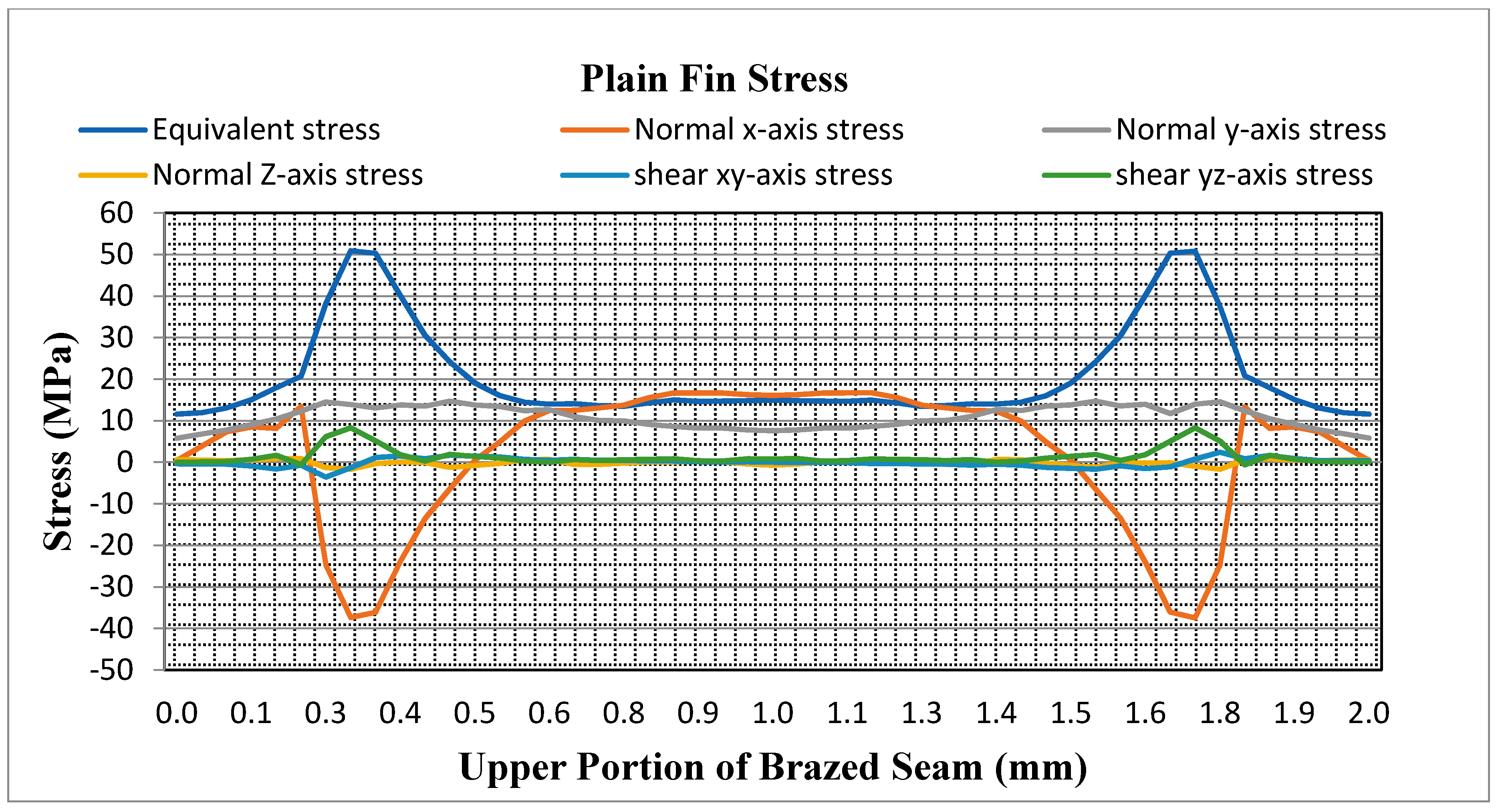
Along the upper face of the brazed seam, using both the full brazed seam and different zones techniques, stress has decreased using latter method by 18 %. Hence, if there is variable strength along the upper face of the braze seam, stresses decrease significantly, but that is not critical for failure. Along the lower face y-axis, stress using the different zones technique is increased by 13% and becomes critical as becomes close to the yield strength of the filler material. So, the variable strength in the brazed seam is critical and more reliable for failure along the lower face of the braze seam, which happens due to the variable heat input in the brazed joints.
(b)
For vertical strength plain fins, stresses are again increased when the different zones technique is used by 5% as compared to full brazed seam method. So, by using the different zones technique, the reliability of the PFHE can be further improved.
(c)
Hence, the applying different zones technique to the braze seam has a significant effect on stresses magnitude in the PFHE. Stresses magnitudes have changed especially along the y-axis and the equivalent stress for both the horizontal and vertical directions of the fin brazed joints.
From the above discussion, it can be concluded that the plain fin braze seam stresses can be better predicted using the different zones technique as compared to the full brazed seam analysis, especially in critical areas.

Author Contributions

Conceptualization, M.H.S. and N.A.S.; methodology, M.H.S. and U.M.N.; software, M.H.S.; validation, M.H.S. and N.A.S.; formal analysis, U.M.N. and M.I.; investigation, A.G.; resources, M.H.S. and N.A.S.; data curation, M.H.S.; writing—original draft preparation, M.H.S. and U.M.N.; writing—review and editing, M.H.S., N.A.S., and U.M.N.; visualization, M.I. and A.G.; supervision, N.A.S. and U.M.N.; project administration, U.M.N. and A.G.; data visualization, S.L. All authors have read and agreed to the published version of the manuscript.

Funding

The authors acknowledge the Ministry of Education and the Deanship of Scientific Research, Najran University, Kingdom of Saudi Arabia, under code number NU/ESCI/19/001 for providing the financial resources to support open access publication.

Acknowledgments

The author acknowledges the support provided to this study by the International Islamic University, Islamabad, Pakistan, and Najran University, Kingdom of Saudi Arabia.

Conflicts of Interest

The authors declare no conflict of interest

Nomenclature

δ v Equivalent Stress
δ 1 First Principle Stress
δ 2 Second Principle Stress
δ 3 Third Principle Stress
δ y e i l d Yield Strength
R δ Normal Stress Ratio
R τ Shear Stress Ratio
δ Maximum Normal Stress Acting on the Braze Joint
τ Maximum Shear Stress Acting on Braze Joint
δ o Tensile Strength of Brazed Joint
τ o Shear Strength of Brazed Joint
δ s Strength of Material
L Load Applied
α C E T Co-efficient of Thermal Expansion for Required Material
δ t Thermal Stress in the Material
E Modulus of Elasticity
δ y Yield Stress

References

  1. Popov, D.; Fikiin, K.; Stankov, B.; Alvarez, G.; Youbi-Idrissi, M.; Damas, A.; Evans, J.; Brown, T. Cryogenic heat exchangers for process cooling and renewable energy storage: A review. Appl. Therm. Eng. 2019, 153, 275–290. [Google Scholar] [CrossRef]
  2. Lim, W.; Choi, K.; Moon, I. Current status and perspectives of liquefied natural gas (LNG) plant design. Ind. Eng. Chem. Res. 2013, 52, 3065–3088. [Google Scholar] [CrossRef]
  3. Raja, B.D.; Jhala, R.; Patel, V. Many-objective optimization of cross-flow plate-fin heat exchanger. Int. J. Therm. Sci. 2017, 118, 320–339. [Google Scholar] [CrossRef]
  4. Guo, K.; Zhang, N.; Smith, R. Design optimisation of multi-stream plate fin heat exchangers with multiple fin types. Appl. Therm. Eng. 2018, 131, 30–40. [Google Scholar] [CrossRef] [Green Version]
  5. Juan, D.; Hai-Tao, Z. Numerical simulation of a plate-fin heat exchanger with offset fins using porous media approach. Heat Mass Transf. 2018, 54, 745–755. [Google Scholar] [CrossRef]
  6. Ligterink, N.; Hageraats-Ponomareva, S.; Velthuis, J. Mechanical integrity of PFHE in LNG liquefaction process. Energy Procedia 2012, 26, 49–55. [Google Scholar] [CrossRef] [Green Version]
  7. Khoshvaght-Aliabadi, M.; Jafari, A.; Sartipzadeh, O.; Salami, M. Thermal–hydraulic performance of wavy plate-fin heat exchanger using passive techniques: Perforations, winglets, and nanofluids. Int. Commun. Heat Mass Transf. 2016, 78, 231–240. [Google Scholar] [CrossRef]
  8. Li, K.; Wen, J.; Yang, H.; Wang, S.; Li, Y. Sensitivity and stress analysis of serrated fin structure in plate-fin heat exchanger on cryogenic condition. Int. J. Therm. Sci. 2019, 145, 106013. [Google Scholar] [CrossRef]
  9. Ma, H.; Hou, C.; Yang, R.; Li, C.; Ma, B.; Ren, J.; Liu, Y. The influence of structure parameters on stress of plate-fin structures in LNG heat exchanger. J. Nat. Gas Sci. Eng. 2016, 34, 85–99. [Google Scholar] [CrossRef]
  10. Ma, H.; Chen, J.; Cai, W.; Shen, C.; Yao, Y.; Jiang, Y. The influence of operation parameters on stress of plate-fin structures in LNG heat exchanger. J. Nat. Gas Sci. Eng. 2015, 26, 216–228. [Google Scholar] [CrossRef]
  11. Mota, F.A.; Ravagnani, M.A.; Carvalho, E. Comparative Analysis of Two Modeling Approaches for Optimizing Plate Heat Exchangers. Int. J. Phys. Math. Sci. 2015, 8, 629–632. [Google Scholar]
  12. Khoshvaght-Aliabadi, M.; Khoshvaght, M.; Rahnama, P. Thermal-hydraulic characteristics of plate-fin heat exchangers with corrugated/vortex-generator plate-fin (CVGPF). Appl. Therm. Eng. 2016, 98, 690–701. [Google Scholar] [CrossRef]
  13. Shahdad, I.; Fazelpour, F. Numerical analysis of the surface and geometry of plate fin heat exchangers for increasing heat transfer rate. Int. J. Energy Environ. Eng. 2018, 9, 155–167. [Google Scholar] [CrossRef] [Green Version]
  14. Peng, X.; Li, D.; Li, J.; Jiang, S.; Gao, Q. Improvement of Flow Distribution by New Inlet Header Configuration with Splitter Plates for Plate-Fin Heat Exchanger. Energies 2020, 13, 1323. [Google Scholar] [CrossRef] [Green Version]
  15. Ameur, H.; Sahel, D.; Menni, Y. Numerical investigation of the performance of perforated baffles in a plate-fin heat exchanger. Therm. Sci. 2020, 90. [Google Scholar] [CrossRef] [Green Version]
  16. Ramachandra, K.S.; Manjunatha, S.S.; Seetharamu, K.N. Performance analysis of plate-fin heat exchanger used for case drain oil cooling application in variable displacement pumps. J. Phys. Conf. Ser. 2020, 1473, 012022. [Google Scholar] [CrossRef]
  17. Onah, T.; Nwankwo, A.; Enugu, E.N. Design and Development of a Trapezoidal Plate Fin Heat Exchanger for the Prediction of Heat Exchanger Effectiveness. J. Energy Technol. Policy 2019, 9, 2224–3232. [Google Scholar]
  18. Nagarajan, V.; Chen, Y.; Wang, Q.; Ma, T. Hydraulic and thermal performances of a novel configuration of high temperature ceramic plate-fin heat exchanger. Appl. Energy 2014, 113, 589–602. [Google Scholar] [CrossRef]
  19. Ma, H.; Cai, W.; Zheng, W.; Chen, J.; Yao, Y.; Jiang, Y. Stress characteristics of plate-fin structures in the cool-down process of LNG heat exchanger. J. Nat. Gas Sci. Eng. 2014, 21, 1113–1126. [Google Scholar] [CrossRef]
  20. Ma, H.; Cai, W.; Yao, Y.; Jiang, Y. Investigation on stress characteristics of plate-fin structures in the heat-up process of LNG heat exchanger. J. Nat. Gas Sci. Eng. 2016, 30, 256–267. [Google Scholar] [CrossRef]
  21. Ma, H.; Qin, G.; Bai, X.; Wang, L.; Liang, Z. Effect of initial temperature on joint of aluminum alloy to galvanized steel welded by MIG arc brazing-fusion welding process. Int. J. Adv. Manuf. Technol. 2016, 86, 3135–3143. [Google Scholar] [CrossRef]
  22. Zhang, M.; Chen, G.; Zhang, Y.; Wu, K. Research on microstructure and mechanical properties of laser keyhole welding–brazing of automotive galvanized steel to aluminum alloy. Mater. Des. 2013, 45, 24–30. [Google Scholar] [CrossRef]
  23. Sillapasa, K.; Surapunt, S.; Miyashita, Y.; Mutoh, Y.; Seo, N. Tensile and fatigue behavior of SZ, HAZ and BM in friction stir welded joint of rolled 6N01 aluminum alloy plate. Int. J. Fatigue 2014, 63, 162–170. [Google Scholar] [CrossRef]
  24. Wei, C.; Zhang, J.; Yang, S.; Tao, W.; Wu, F.; Xia, W. Experiment-based regional characterization of HAZ mechanical properties for laser welding. Int. J. Adv. Manuf. Technol. 2015, 78, 1629–1640. [Google Scholar] [CrossRef]
  25. Zhang, H.; Feng, J.; He, P.; Hackl, H. Interfacial microstructure and mechanical properties of aluminium–zinc-coated steel joints made by a modified metal inert gas welding–brazing process. Mater. Charact. 2007, 58, 588–592. [Google Scholar] [CrossRef]
  26. Dørum, C.; Lademo, O.-G.; Myhr, O.R.; Berstad, T.; Hopperstad, O.S. Finite element analysis of plastic failure in heat-affected zone of welded aluminium connections. Comput. Struct. 2010, 88, 519–528. [Google Scholar] [CrossRef]
  27. Zhang, L.; Xuan, J.; Shi, T. Obtaining More Accurate Thermal Boundary Conditions of Machine Tool Spindle Using Response Surface Model Hybrid Artificial Bee Colony Algorithm. Symmetry 2020, 12, 361. [Google Scholar] [CrossRef] [Green Version]
  28. Saeed, T.; Abbas, I.; Marin, M. A GL Model on Thermo-Elastic Interaction in a Poroelastic Material Using Finite Element Method. Symmetry 2020, 12, 488. [Google Scholar] [CrossRef] [Green Version]
  29. Ke, H.; Lin, Y.; Ke, Z.; Xiao, Q.; Wei, Z.; Chen, K.; Xu, H. Analysis Exploring the Uniformity of Flow Distribution in Multi-Channels for the Application of Printed Circuit Heat Exchangers. Symmetry 2020, 12, 314. [Google Scholar] [CrossRef] [Green Version]
  30. Saggu, M.H.; Sheikh, N.A.; Niazi, U.M.; Irfan, M.; Glowacz, A. Predicting the Structural Reliability of LNG Processing Plate-Fin Heat Exchanger for Energy Conservation. Energies 2020, 13, 2175. [Google Scholar] [CrossRef]
  31. Nayeb-Hashemi, H.; Lockwood, M. The effect of processing variables on the microstructures and properties of aluminum brazed joints. J. Mater. Sci. 2002, 37, 3705–3713. [Google Scholar] [CrossRef]
  32. Meuwissen, M.; Oomens, C.; Baaijens, F.; Petterson, R.; Janssen, J. Determination of the elasto-plastic properties of aluminium using a mixed numerical–experimental method. J. Mater. Process. Technol. 1998, 75, 204–211. [Google Scholar] [CrossRef]
  33. Gere, J.M.; Goodno, B.J. Mechanics of Materials, 8th ed.; Cengage Learning: Stamford, CT, USA, 2009. [Google Scholar]
  34. Ma, H.; He, B.; Lan, S.; Liu, Y.; Gao, X.; Xue, X.; Hou, C.; Li, C. The stress characteristics of plate-fin structures at the different operation parameters of LNG heat exchanger. Oil Gas Sci. Technol. Rev. d’IFP Energ. Nouv. 2018, 73, 13. [Google Scholar] [CrossRef] [Green Version]
  35. Kim, H.-H.; Lee, S.-B. Effect of a brazing process on mechanical and fatigue behavior of alclad aluminum 3005. J. Mech. Sci. Technol. 2012, 26, 2111–2115. [Google Scholar] [CrossRef]
  36. Biswas, R.; Strawn, R.C. Tetrahedral and Hexahedral mesh adaptation for CFD problems. Appl. Numer. Math. 1998, 26, 135–151. [Google Scholar] [CrossRef]
  37. Shah, R.; Focke, W. Plate heat exchangers and their design theory. Heat Transf. Equip. Des. 1988, 227, 254. [Google Scholar]
  38. Lin, M.-T.; El-Deiry, P.; Chromik, R.R.; Barbosa, N.; Brown, W.L.; Delph, T.J.; Vinci, R.P. Temperature-dependent microtensile testing of thin film materials for application to microelectromechanical system. Microsyst. Technol. 2006, 12, 1045–1051. [Google Scholar] [CrossRef]
  39. Yamamoto, N.; Makino, H.; Yamamoto, T. Young’s modulus and coefficient of linear thermal expansion of ZnO conductive and transparent ultra-thin films. Adv. Mater. Sci. Eng. 2011, 2011, 136127. [Google Scholar] [CrossRef] [Green Version]
  40. Bray, J. Properties and selection: Nonferrous alloys and special purpose materials. Asm Met. Handb. 1990, 92. [Google Scholar]
  41. Shigley, J.E. Shigley’s Mechanical Engineering Design; Tata McGraw-Hill Education: New York, NY, USA, 2011. [Google Scholar]
  42. Flom, Y. Evaluation of brazed joints using failure assessment diagram. In Proceedings of the 5th International Brazing and Soldering Conference (IBSC), Las Vegas, NV, USA, 22–25 April 2012. [Google Scholar]
Figure 1. Plate fin heat exchanger (PFHE) assembly and flow of natural gas (NG) and mix refrigerant (MR).
Energies 13 03624 g001
Figure 2. Parts of a PFHE.
Energies 13 03624 g002
Figure 3. Two methods for analyzing a PHFE. (a) The braze seam as a single unit. (b) The braze seam as three subunits (interface strength on both ends and filler material strength at center).
Energies 13 03624 g003
Figure 4. Strength of intermediate region between Al 3003 and Al 4004 [30].
Energies 13 03624 g004
Figure 5. Stresses in upper braze seam of PFHE, (a) Equivalent stress (MPa); (b) normal stress (MPa); (c) shear stress (MPa).
Energies 13 03624 g005
Figure 6. Stresses along the upper face of the braze seam.
Energies 13 03624 g006
Figure 7. Equivalent stresses in the upper portion of the brazed seam using both techniques for a plain fin brazed seam.
Energies 13 03624 g007
Figure 8. Stresses along the lower face of the braze seam.
Energies 13 03624 g008
Figure 9. Equivalent and y-axis stresses in the lower portion of the brazed seam using both techniques for the plain fin brazed seam.
Energies 13 03624 g009
Figure 10. Stresses in PFHE. (a) Equivalent stress; (b) normal stress; (c) shear stress.
Energies 13 03624 g010
Figure 11. Stresses in vertical direction of fin.
Energies 13 03624 g011
Figure 12. Equivalent stresses in vertical direction of brazed seam using both techniques for a plain fin.
Energies 13 03624 g012
Table 1. Fin dimensions.
Fin ProfileHeight of Fin
(mm)
Thickness of Fin
(mm)
Thickness of Plate (mm)Depth of PFHE (mm)Total Flow Area per Fin
(mm2)
Brazing Seam Thickness (mm)
First Method
Brazing Seam Thickness (mm)
Second Method
Zone 1Zone 2Zone 3
Plain fin [19]60.41.62.53.120.10.0330.0340.033
Table 2. Properties of aluminum used for fin analysis.
Material Name [9]Range of
Temperature (K) [9]
Variation in Modulus of Elasticity with Temperature (E) GPa [9,38]Variation in Co-efficient of Thermal Expansion (10−6) (1/K) [9,39]Pre-Brazed Yield Strength from Literature
(MPa)
[34]
Post Brazed Yield Strength from Experiment
(MPa)
[31,35,40,41]
Al 300330568.922.4145124.2
20570.619.7145124.2
19572.416.9145124.2
17573.215.9145124.2
14574.514.4145124.2
Al 400430594.615.1142112
20596.414.9142112
19598.214.7142112
17598.814.6142112
14599.614.5142112
Interface brazed3057715.1142109
20582.514.8142109
19583.114.6142109
17584.314.5142109
1458614.5142109
Table 3. Modified factor of safety (FOS) for a plain braze seam along the upper face.
Stress TypeTypePrevious Factor of SafetyModified Factor of Safety
Equivalent StressPlain2.12.6
Normal x-axis StressPlain2.82.8
Normal y-axis StressPlain9.39.3
Table 4. Modified FOS for a plain fin along the lower face of the braze seam.
Stress TypeTypePrevious Factor of SafetyModified Factor of Safety
Equivalent StressPlain1.31.1
Normal x-axis StressPlain5.65.6
Normal y-axis StressPlain1.31.1
Shear yz-axis StressPlain4.14.1
Table 5. Modified FOS for the plain fin brazed seam along the vertical direction.
Stress TypeTypePrevious Factor of SafetyModified Factor of Safety
Equivalent StressPlain1.61.5
Normal x-axis StressPlain3.23.2
Normal y-axis StressPlain3.73.7
Shear yz-axis StressPlain2.22.2
Table 6. Modified FOS for a plain fin brazed seam along the x‐y direction.
Margin of Safety ForUpper Face of Braze Seam
(Full Braze Seam)
Modification in Upper Face of Braze Seam (Different Zones Technique)Lower Face of Braze Seam
(Full Braze Seam)
Modification in Lower Face of Braze Seam (Different Zones Technique)Vertical Direction of Braze Seam
(Full Braze Seam)
Modification in Vertical Direction of Braze Seam
(Different Zones Technique)
Along X-axis
Plain1.71.74.54.522
Along Y-Axis
Plain5.95.90.30.20.90.9

