Energy and Force Optimization of a Network of Novel Electromagnetic Soft Actuators


Abstract
1. Introduction
2. Materials and Methods
2.1. Design Parameters of Networked Electromagnetic Soft Actuators and Force Formulation
2.1.1. Electromagnetic Force of Two Antagonistic Coils
2.1.2. Network of Electromagnetic Soft Actuators
2.2. Case Study: an Active Elbow Brace
2.2.1. Optimization of Single ESA
2.2.2. Optimal Design of a Networked ESAs
3. Results
4. Discussion
Author Contributions
Funding
Conflicts of Interest
Abbreviations
| ESA | Electromagnetic Soft Actuator |
References
- Haddadin, S.; Albu-Schäffer, A.; Hirzinger, G. Safety Evaluation of Physical Human–Robot Interaction via Crash-Testing. Robot. Sci. Syst. 2007, 3, 217–224. [Google Scholar]
- De Santis, A.; Siciliano, B.; De Luca, A.; Bicchi, A. An atlas of physical human–robot interaction. Mech. Mach. Theory 2008, 43, 253–270. [Google Scholar] [CrossRef]
- Haddadin, S.; Albu-Schäffer, A.; Hirzinger, G. Requirements for safe robots: Measurements, analysis and new insights. Int. J. Robot. Res. 2009, 28, 1507–1527. [Google Scholar] [CrossRef]
- Alami, R.; Albu-Schäffer, A.; Bicchi, A.; Bischoff, R.; Chatila, R.; De Luca, A.; De Santis, A.; Giralt, G.; Guiochet, J.; Hirzinger, G.; et al. Safe and dependable physical human-robot interaction in anthropic domains: State of the art and challenges. In Proceedings of the 2006 IEEE/RSJ International Conference on Intelligent Robots and Systems, Beijing, China, 9–13 October 2006; pp. 1–16. [Google Scholar]
- Suzumori, K.; Endo, S.; Kanda, T.; Kato, N.; Suzuki, H. A bending pneumatic rubber actuator realizing soft-bodied manta swimming robot. In Proceedings of the 2007 IEEE International Conference on Robotics and Automation, Rome, Italy, 14 April 2007; pp. 4975–4980. [Google Scholar]
- Polygerinos, P.; Lyne, S.; Wang, Z.; Nicolini, L.F.; Mosadegh, B.; Whitesides, G.M.; Walsh, C.J. Towards a soft pneumatic glove for hand rehabilitation. In Proceedings of the 2013 IEEE/RSJ International Conference on Intelligent Robots and Systems, Tokyo, Japan, 7 November 2013; pp. 1512–1517. [Google Scholar]
- Yap, H.K.; Lim, J.H.; Nasrallah, F.; Goh, J.C.; Yeow, R.C. A soft exoskeleton for hand assistive and rehabilitation application using pneumatic actuators with variable stiffness. In Proceedings of the 2015 IEEE International Conference on Robotics and Automation (ICRA), Seattle, WA, USA, 30 May 2015; pp. 4967–4972. [Google Scholar]
- Mata, A.; Fleischman, A.J.; Roy, S. Characterization of polydimethylsiloxane (PDMS) properties for biomedical micro/nanosystems. Biomed. Microdevices 2005, 7, 281–293. [Google Scholar] [CrossRef] [PubMed]
- Rodrigue, H.; Wang, W.; Kim, D.R.; Ahn, S.H. Curved shape memory alloy-based soft actuators and application to soft gripper. Compos. Struct. 2017, 176, 398–406. [Google Scholar] [CrossRef]
- Fang, L.; Fang, T.; Liu, X.; Chen, S.; Lu, C.; Xu, Z. Near-Infrared Light Triggered Soft Actuators in Aqueous Media Prepared from Shape-Memory Polymer Composites. Macromol. Mater. Eng. 2016, 301, 1111–1120. [Google Scholar] [CrossRef]
- Choi, H.; Ryew, S.; Jung, K.; Kim, H.; Jeon, J.W.; Nam, J.; Maeda, R.; Tanie, K. Microrobot actuated by soft actuators based on dielectric elastomer. In Proceedings of the IEEE/RSJ International Conference on Intelligent Robots and Systems, Lausanne, Switzerland, 4 October 2002; Volume 2, pp. 1730–1735. [Google Scholar]
- Gu, G.Y.; Gupta, U.; Zhu, J.; Zhu, L.M.; Zhu, X. Modeling of viscoelastic electromechanical behavior in a soft dielectric elastomer actuator. IEEE Trans. Robot. 2017, 33, 1263–1271. [Google Scholar] [CrossRef]
- Nguyen, C.T.; Phung, H.; Nguyen, T.D.; Jung, H.; Choi, H.R. Multiple-degrees-of-freedom dielectric elastomer actuators for soft printable hexapod robot. Sensors Actuators A Phys. 2017, 267, 505–516. [Google Scholar] [CrossRef]
- Miriyev, A.; Stack, K.; Lipson, H. Soft material for soft actuators. Nat. Commun. 2017, 8, 1–8. [Google Scholar] [CrossRef] [PubMed]
- Lipson, H. Challenges and opportunities for design, simulation, and fabrication of soft robots. Soft Robot. 2014, 1, 21–27. [Google Scholar] [CrossRef]
- Do, T.N.; Phan, H.; Nguyen, T.Q.; Visell, Y. Miniature soft electromagnetic actuators for robotic applications. Adv. Funct. Mater. 2018, 28, 1800244. [Google Scholar] [CrossRef]
- Yang, Y.P.; Liu, J.J.; Ye, D.H.; Chen, Y.R.; Lu, P.H. Multiobjective optimal design and soft landing control of an electromagnetic valve actuator for a camless engine. IEEE/ASME Trans. Mech. 2012, 18, 963–972. [Google Scholar] [CrossRef]
- Ebrahimi, N.; Nugroho, S.; Taha, A.F.; Gatsis, N.; Gao, W.; Jafari, A. Dynamic actuator selection and robust state-feedback control of networked soft actuators. In Proceedings of the 2018 IEEE International Conference on Robotics and Automation (ICRA), Brisbane, Australia, 25 May 2018; pp. 2857–2864. [Google Scholar]
- Jafari, A.; Ebrahimi, N. Electromagnetic Soft Actuators. U.S. Patent App. 16/457,452, 2 January 2020. [Google Scholar]
- Ebrahimi, N.; Schimpf, P.; Jafari, A. Design optimization of a solenoid-based electromagnetic soft actuator with permanent magnet core. Sens. Actuators A Phys. 2018, 284, 276–285. [Google Scholar] [CrossRef]
- Liu, D.K.C.; Friend, J.; Yeo, L. A brief review of actuation at the micro-scale using electrostatics, electromagnetics and piezoelectric ultrasonics. Acoust. Sci. Technol. 2010, 31, 115–123. [Google Scholar] [CrossRef]
- Azzerboni, B.; Asti, G.; Pareti, L.; Ghidini, M. Magnetic Nanostructures in Modern Technology, Chapter 2-Spintronics, Magnetic MEMS and Recording; Springer: Dordrecht, The Netherlands, 2007; pp. 237–306. [Google Scholar]
- Kemp, B.; Grzegorczyk, T.; Kong, J. Lorentz force on dielectric and magnetic particles. J. Electromagn. Waves Appl. 2006, 20, 827–839. [Google Scholar] [CrossRef]
- Pappas, P. The original Ampere force and Biot–Savart and Lorentz forces. Il Nuovo Cimento B (1971–1996) 1983, 76, 189–197. [Google Scholar] [CrossRef]
- Bryce, C.D.; Armstrong, A.D. Anatomy and biomechanics of the elbow. Orthop. Clin. N. Am. 2008, 39, 141–154. [Google Scholar] [CrossRef] [PubMed]


| Characteristics | Value | Unit |
|---|---|---|
| Range of Flexion-Extension | 0–140 | Degree |
| Torque | 40–60 | Nm |
| Weight | 150–300 | g |
| Volume | 800 | cm |
| Mixing Ratio (%) | Flux Density (Tesla) | Maximum Passive Elongation Ratio (%) |
|---|---|---|
| 8–12 | 0.4–0.5 | 70–73 |
| 12–16 | 0.5–0.57 | 60–70 |
| 16–20 | 0.57–0.63 | 48–60 |
| 20–24 | 0.63–0.83 | 40–48 |
| 24–28 | 0.83–0.9 | 35–40 |
| Characteristics | Value | Unit |
|---|---|---|
| Inner diameter of flexible wire | 4 | mm |
| Length of the coil | 10 | mm |
| Cross-section profile | 400 | mm |
| Coil volume | 500 | mm |
| Mixing ratio of flexible magnet | 20–24 | % |
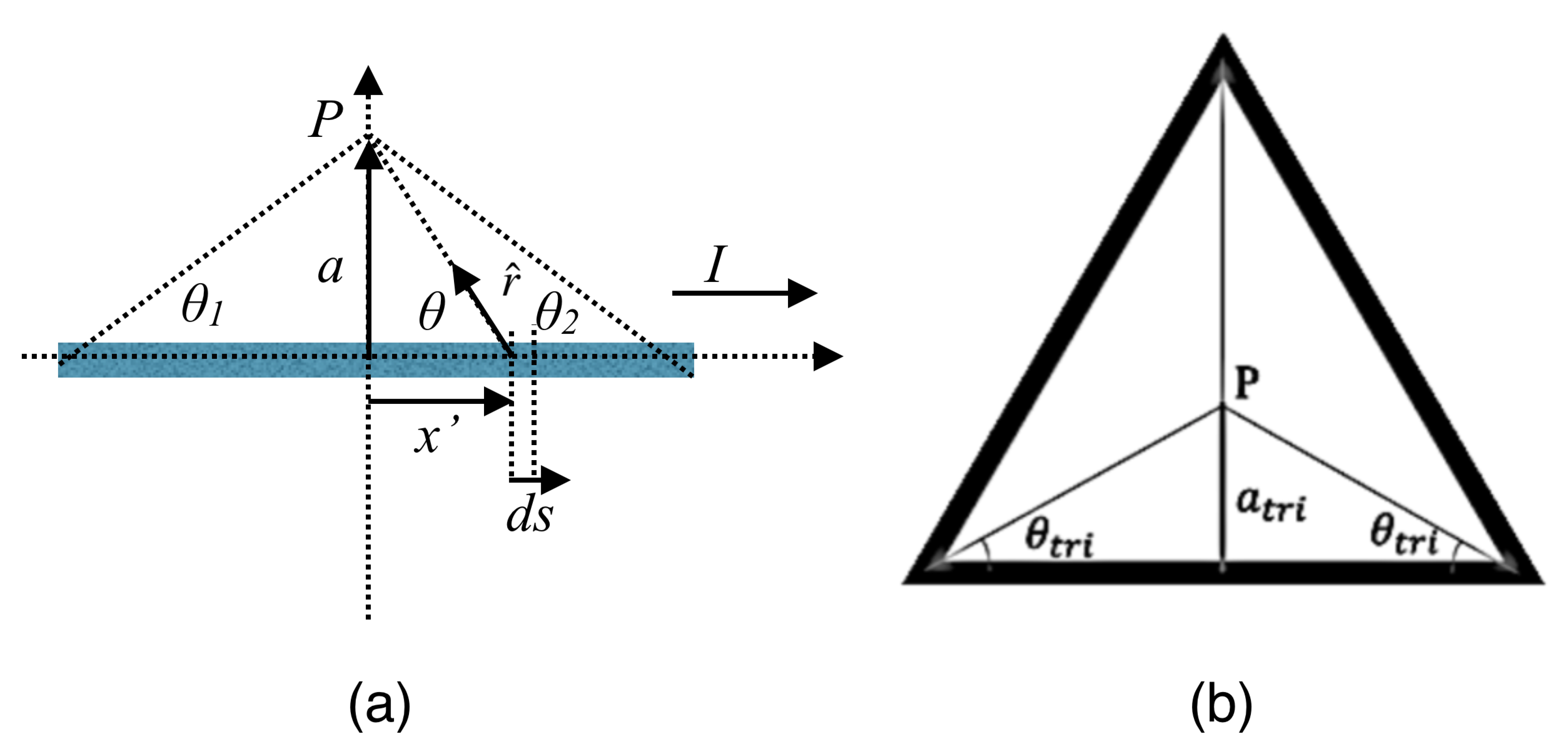
| Coil Section Profile | Magnetic Field Out of One Loop Coil | Ratio of Magnetic Fields |
|---|---|---|
| Triangle | ||
| Square | ||
| Pentagon | ||
| Hexagon | ||
| Octagon | ||
| Circle |
| Coil Section Profile | Force over Perimeter Ratio () | () |
|---|---|---|
| Triangle | 1 | |
| Square | 1.089 | |
| Pentagon | 0.977 | |
| Hexagon | 1.152 | |
| Octagon | 0.960 | |
| Circle | 1.096 |
© 2020 by the authors. Licensee MDPI, Basel, Switzerland. This article is an open access article distributed under the terms and conditions of the Creative Commons Attribution (CC BY) license (http://creativecommons.org/licenses/by/4.0/).
Share and Cite
Ebrahimi, N.; Jafari, A. Energy and Force Optimization of a Network of Novel Electromagnetic Soft Actuators. Energies 2020, 13, 3572. https://doi.org/10.3390/en13143572
Ebrahimi N, Jafari A. Energy and Force Optimization of a Network of Novel Electromagnetic Soft Actuators. Energies. 2020; 13(14):3572. https://doi.org/10.3390/en13143572
Chicago/Turabian StyleEbrahimi, Nafiseh, and Amir Jafari. 2020. "Energy and Force Optimization of a Network of Novel Electromagnetic Soft Actuators" Energies 13, no. 14: 3572. https://doi.org/10.3390/en13143572
APA StyleEbrahimi, N., & Jafari, A. (2020). Energy and Force Optimization of a Network of Novel Electromagnetic Soft Actuators. Energies, 13(14), 3572. https://doi.org/10.3390/en13143572