Article

A Selective Fault Clearing Scheme for a Hybrid VSC-LCC Multi-Terminal HVdc System

by
Naushath M. Haleem
1,*,
Athula D. Rajapakse
1,
Aniruddha M. Gole
1 and
Ioni T. Fernando
2
1
Department of Electrical and Computer Engineering, University of Manitoba, Winnipeg, MB R3T 2N2, Canada
2
Manitoba Hydro, Winnipeg, MB R3C0G8, Canada
*
Author to whom correspondence should be addressed.
Energies 2020, 13(14), 3554; https://doi.org/10.3390/en13143554
Submission received: 30 April 2020 / Revised: 3 July 2020 / Accepted: 7 July 2020 / Published: 10 July 2020
(This article belongs to the Special Issue Protection of Future Multi-Terminal HVDC Grids)

Abstract

:
A selective fault clearing scheme is proposed for a hybrid voltage source converter (VSC)-line commutated converter (LCC) multi-terminal high voltage direct current (HVdc) transmission structure in which two small capacity VSC stations tap into the main transmission line of a high capacity LCC-HVdc link. The use of dc circuit breakers (dc CBs) on the branches connecting to VSCs at the tapping points is explored to minimize the impact of tapping on the reliability of the main LCC link. This arrangement allows clearing of temporary faults on the main LCC line as usual by force retardation of the LCC rectifier. The faults on the branches connecting to VSC stations can be cleared by blocking insulated gate bipolar transistors (IGBTs) and opening ac circuit breakers (ac CB), without affecting the main line’s performance. A local voltage and current measurement based fault discrimination scheme is developed to identify the faulted sections and pole(s), and trigger appropriate fault recovery functions. This fault discrimination scheme is capable of detecting and discriminating short circuits and high resistances faults in any branch well before 2 ms. For the test grid considered, 6 kA, 2 ms dc CBs can easily facilitate the intended fault clearing functions and maintain the power transfer through healthy pole during single-pole faults.

1. Introduction

In many cases, HVdc transmission lines are built with some spare capacity for future expansion or to meet other design requirements [1]. This situation exists on the present-day Bipoles I and II of Manitoba Hydro’s HVdc transmission system. The potential renewable energy resources and new load centres can be integrated to the electricity grid with less cost using the spare capacity of the existing HVdc lines. However, high-power interfacing electronics are required for tapping into HVdc transmission lines. At present, the majority of existing bulk power HVdc transmission lines use line commutated converter (LCC) technology due to superior economics and proven technological performances [2]. On the other hand, the voltage source converter (VSC) offers a practical approach for tapping. VSCs also offer the ability to change the direction of power flow for meeting the instantaneous power balancing requirements [3]. The black start capability [4] and the ability to connect to weak ac systems [5] are very useful when integrating remote or isolated renewable power generation systems [6].
The two converter technologies can be combined in many different ways. A VSC can be combined in series with an LCC at each converter station as proposed in [7,8,9]. Different ways of implementing hybrid LCC-VSC two-terminal or multi-terminal HVdc (MT-HVdc) systems, where the individual converter stations are based on different technologies, can be found in [10,11,12,13,14,15,16,17,18,19,20]. Two main classes of hybrid MT-HVdc systems are:
  • A number of VSC rectifier stations, typically connected to offshore wind farms, linked to a large onshore LCC inverter station supplying one or more major load centres [10,11,12],
  • One large LCC rectifier, typically connected to a large hydropower station, linked to a number of small VSC inverters supplying urban load stations [13,14,15,16,17].
In the first configuration, the advantages of VSC stations such as small footprint, ability to connect to a weak ac system are exploited in the offshore rectifiers, and the economy of LCC station in building large converter station is exploited in the onshore inverter. In the second configuration, the economy of LCC station is exploited in building a large rectifier station connected to a strong system and the advantage of the small footprint of VSC stations is exploited in building the converters supplying urban load centres. A real-world example for the second type is the Woudong hybrid three-terminal grid, which comprises an 8 GW LCC rectifier and two VSC inverters rated 5 GW and 3 GW [14]. This scheme is under construction and will be commissioned in the year 2022 [21]. In contrast, this paper considers tapping into an existing LCC link using VSC converters as described in [17,18,19,20].
Modern VSC stations are built using modular multilevel converter (MMC) technology using half-bridge sub-modules (HB-SM) or full-bridge sub-modules (FB-SM) [22]. Although the FB-SM option is more flexible and has the inherent DC fault current blocking capability, it is relatively expensive and currently not widely applied in practical systems. In contrast, HB-SM MMCs are more common and have been used in VSC based multi-terminal HVdc systems [23,24].
A fault clearing scheme for hybrid LCC-VSC MT-HVdc with HB-SM MMCs is proposed in [1]. The configuration proposed in [1] is depicted in Figure 1, and the method relies on ac CBs to interrupt fault currents from the VSC rectifier and employs a diode valve in series with the VSC inverters to block dc fault currents.
VSC-A is assumed to be operated either as a rectifier or inverter. In contrast, VSC-B is assumed to be operated only in the inverter mode. To facilitate feeding power from VSC-A during rectifier operation, the diodes connected to VSC-A should be bypassed. Additionally, a series reactor is inserted for limiting the rate of rise of current injected by VSC-A during dc faults. A dc fault is cleared using the following sequence:
  • De-energize all VSC rectifiers by opening their ac CBs to avoid fault current injection from the ac side,
  • Apply force retardation at the LCC rectifier,
  • Open the fast mechanical switches when the current through them are sufficiently small.
Although this method works and can be implemented with the existing technologies, one of its drawbacks is the prolong time to extinguish arcing faults due to the long time taken to dissipate the stored energy in the VSC inductive elements and the transmission line, even after blocking the IGBTs. This is in contrast to LCC HVdc systems, which can quickly reduce dc fault currents by applying forced retardation procedure. Besides that, the series-connected high-power diode valve can be subjected up to 2 pu reverse voltage during the fault transients. Therefore, when a hybrid multi-terminal HVdc transmission system is created by connecting VSC based taps on an existing LCC HVdc link, and if the VSC rectifiers rely on ac side CBs to interrupt dc side fault currents [1], then the dc side fault clearing time increases in comparison to that of the original LCC HVdc link. The fault clearing performance and the reliability of the hybrid VSC-LCC MT-HVdc system proposed in [1] can be improved if high voltage dc circuit breakers (dc CBs) are employed for fast, selective fault isolation. Temporary faults due to flashover are very common in long open conductor overhead transmission lines used in HVdc transmission and therefore fast temporary fault recovery performance is essential [25]. Recent developments in high voltage dc CB technology include full-scale prototypes and field installations [24,26]. Technically viable commercial dc CB solutions are expected to emerge in the near future. An enhanced protection scheme having higher selectivity and higher security is developed in this paper to use in conjunction with strategically placed dc CBs.
Although selective fault clearing in purely VSC based MT-HVdc systems has been an active research area in recent years [27,28,29], the technology is not well established, especially for hybrid LCC-VSC MT-HVdc transmission systems that comprise of multiples zones, and gaps exist in the understanding. In contrast to the dc fault clearing approach proposed in [1], a selective fault clearing scheme needs a fault detection and discrimination scheme suitable for hybrid LCC-VSC multi-terminal systems having multiple protection zones.
In [30], a traveling wave-based fault location scheme is proposed for two-terminal HVdc links, and this concept is extended and applied for the protection of hybrid VSC-LCC HVdc systems in [31,32,33,34,35]. Most of the fault discrimination schemes presented for hybrid LCC-VSC HVdc transmission systems are proposed or evaluated for two-terminal HVdc systems [31,32,33,34,35], which typically have a single line protection zone. The traveling-wave protection (TWP) is reportedly considered for Wudongde three-terminal hybrid HVdc project for line protection [33]. A fault discrimination method is proposed in [36] for a hybrid LCC-VSC based MT- HVdc transmission system comprising of multiple zones. The method proposed in [36] uses the ratio of two voltage components at two different frequencies extracted from the fault transient as the fault indicator and claims to be capable of discriminating faults of up to 400 Ω fault resistance in a MT- HVdc system comprising of an LCC rectifier connected to two-VSC inverters. However, in [36] a fault clearing procedure is not discussed and the adequacy of the proposed scheme for successful fault clearing is not fully demonstrated.
Furthermore, without having a complete protection scheme that discriminates the faults in different zones, and a fault recovery scheme that invokes appropriate actions depending on the faulted zone and fault type, the potential fault recovery performances cannot be evaluated. The fault discrimination scheme should be capable of discriminating faults at each zone, up-to a fair value of fault resistance expected in a typical hybrid LCC-VSC based multi-terminal system. In addition, the fault discrimination method should be able to make decisions within a very short duration as dictated by the dc CB limitations. This is because a dc CB has to interrupt the rapidly rising fault currents before they exceed the maximum breakable current. The fault current injected through a VSC branch could reach its peak value within a few milliseconds. The fault discrimination speed of the scheme presented in [36], which needs 5 ms time window, may not be adequate with respect to the typical dc CB performance cited in the literature [24,26].
In contrast to the previously mentioned literature, this paper addresses the fault discrimination, fault clearing, and the post-fault recovery performance in a class of hybrid LCC-VSC MT-HVdc schemes in a holistic manner. The configuration of the hybrid LCC-VSC MT-HVdc scheme considered is similar to the one shown in Figure 1 and the main contributions of the paper include (i) development of a complete protection scheme based on the local voltage and current measurements to identify the faulted segment and the conductors involved in the fault within a short time interval after a dc side fault, (ii) demonstration of the suitability of the fault discrimination scheme in terms of the capability of discriminating faults at the boundary of each zone for up to about 50 Ω of fault resistance with a speed that is adequate for meeting the breaking capability of the dc CB prototype presented in [26], (iii) development of a detailed fault recovery procedure that minimizes the extent of outages, and (iv) simulation-based analysis of the proposed algorithms under a variety of possible fault scenarios.

2. Proposed Protection Scheme

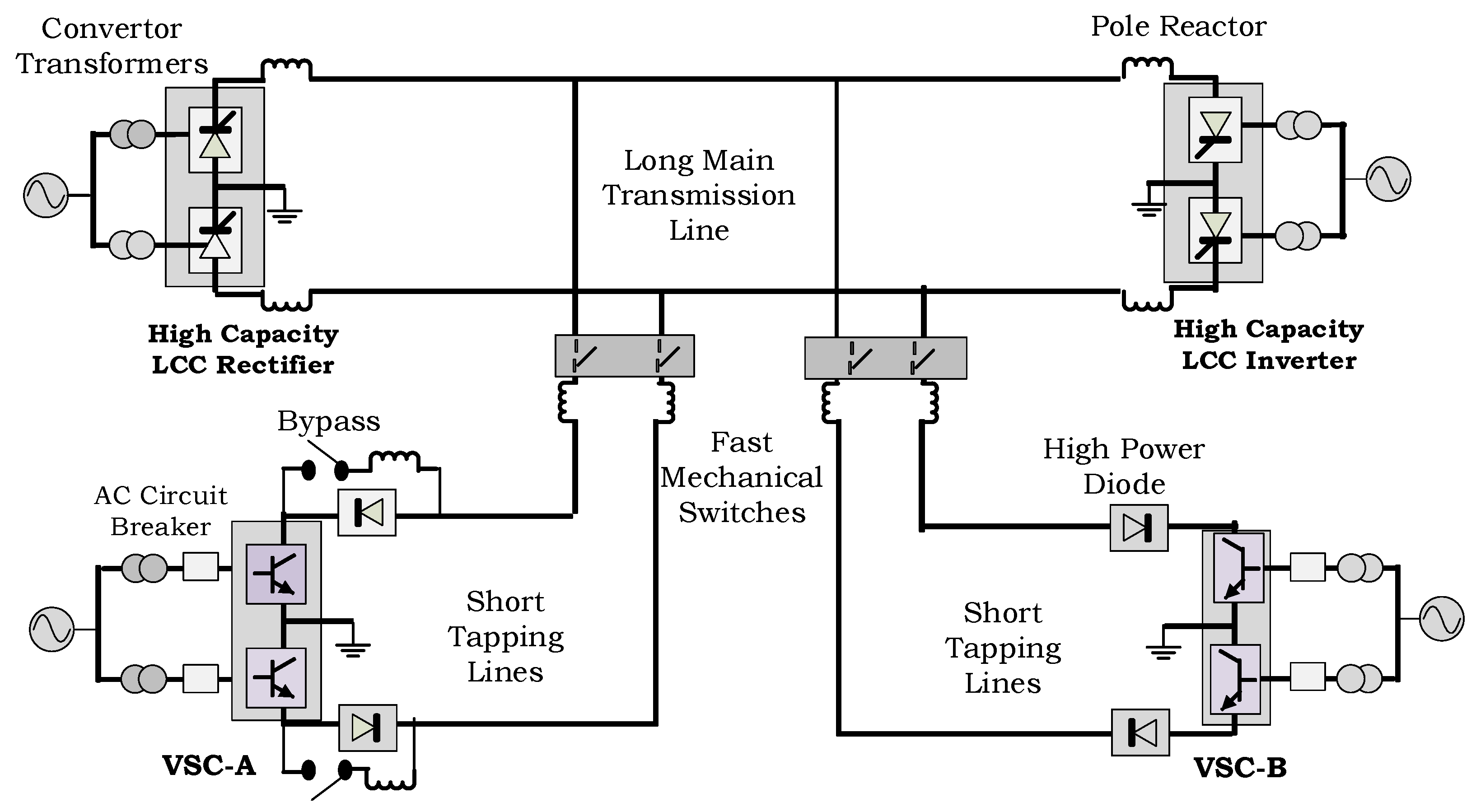
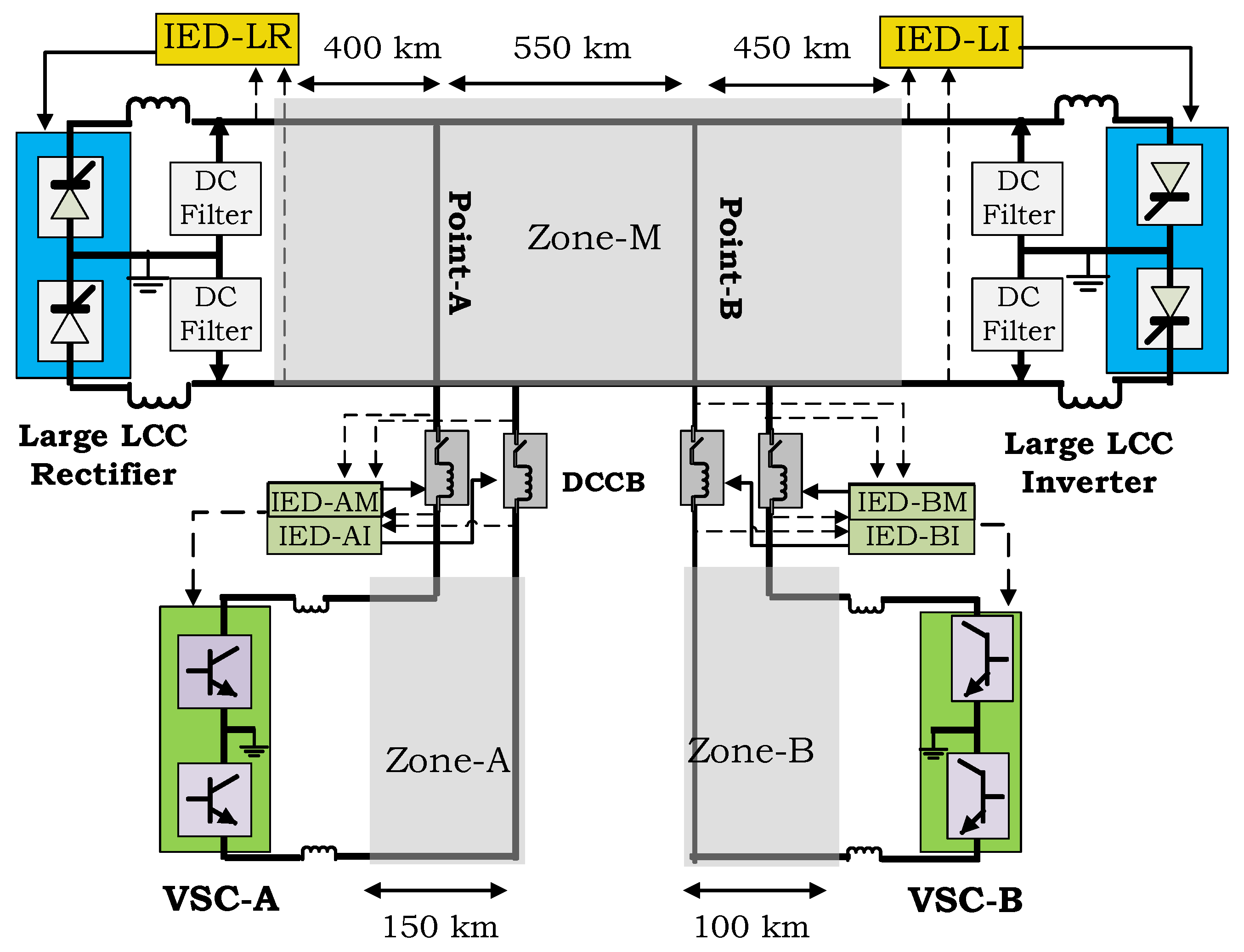
2.1. Key Components and Grid Layout

Figure 2 shows the considered hybrid LCC-VSC MT-HVdc grid layout and the essential elements of the proposed protection scheme.
Two VSC stations with a lower rating compared to the LCC stations are connected through two transmission lines, which are hereafter referred to as VSC branches, to a 1400 km long main transmission link. A bipole HVdc transmissions system without a dedicated metallic return wire similar to Manitoba Bipole-I and -II [37] is considered in this study. It is assumed that earth return mode is allowed for a short period for single-pole fault recovery. The VSC stations are based on more economical HB-SM technology.
A key requirement is to ensure that the reliability of the original LCC line is not degraded due to tapping. In order to minimize the fault clearing and recovery time for temporary dc faults, all HB-SM based MMCs on the affected pole(s) must be immediately disconnected from the dc network. Additionally, during all permanent faults on the VSC branches, the faulted line segment must be disconnected before the stability of the LCC link is affected. This is only possible by using dc CBs for selective fault isolation. In order to maximize the fault recovery performance with a minimum number of dc CBs (which are high-cost items), it is proposed to place a dc CB at each tapping point on the VSC branches. In this configuration, dc CBs perform two main roles:
  • For both temporary and permanent faults on VSC branches, they avoid the impact on the LCC link by promptly disconnecting faulty conductor(s) from the main LCC link.
  • For temporary faults on the main LCC link, they avoid the need for a complete shutdown and restarting of VSC stations by promptly disconnecting faulty conductor(s) from the VSCs. The VSCs that are connected to faulty pole(s) could be switched to static synchronous compensator (STATCOM) mode (i.e., no real power transfer) until the fault on the main transmission line is cleared.
It is necessary to have dc CBs on both poles to perform the above roles. With this arrangement, a VSC station is completely de-energized for faults on the line segment connecting it to the main LCC link. De-energization of a VSC during temporary faults can be avoided by providing additional dc CBs at the VSC terminals, but this is an expensive solution with only a marginal contribution to improve the reliability or safety of the system:
  • Because there is no alternative path for power transfer during a VSC branch fault in the considered layout, isolation of the faulty conductor to preserve the continuity of VSC operation does not offer any significant advantage.
  • Each VSC has its own low-level protection such as IGBT blocking upon fault detection and freewheeling diode protection by firing parallel thyristors [25].
The fault clearing process is initiated with the help of fault discrimination information provided by intelligent electronic devices (IEDs) installed on appropriate places as indicated in Figure 2. The forced retarding fault current blocking mechanism utilized on the LCC terminals is used for the proposed scheme as well. Based on the above reasoning, the dc CB placement shown in Figure 2 is considered as the arrangement that needs the least number of dc CBs for the proposed hybrid VSC-LCC multi-terminal HVdc topology, and it divides the dc network into three protection zones.
In this scheme, it is necessary to discriminate the faults on the main transmission line (Zone-M) from those on the branches connecting VSC-A (Zone-A), and VSC-B (Zone-B); and identify the pole(s) involved in the fault. An intelligent electronics device (IED) capable of the above tasks can be implemented at each tapping point as indicated on Figure 2 with the help of series di/dt limiting inductors, which are an integral part of dc CBs [26,27,28]. The protection IED-A at the tapping point-A comprises two functional units: one denoted as IED-AM to detect faults on the main transmission line, and the other denoted as IED-AI to detect faults on the line connecting the VSC. A similar protection IED is employed at the tapping point B as well.
The coordination of converter stations in this multi-terminal transmission system is important for stable normal operation and fault recovery. The centralized master power controller (MPC), proposed in [1] is considered in this study. Grid energization and co-ordination is carried as described in [6], in which the LCC inverter is operated in the constant extinction angle control mode, while VSC stations are operated in the constant power control mode during normal operation. The LCC rectifier is operated in the constant current control mode. The primary function of the MPC is to calculate the current order for the LCC rectifier to fulfil power demand at the LCC inverter while considering the instantaneous current injections from each VSC station. For example, the current order of the positive pole (P-pole) is calculated using Equation (1).
I O _ P = S L I P [ K L I · P r e f L I P V ` D C L I P V ` D C L I N + S V A P · K V A · P r e f V A P V ` D C V A P V ` D C V A N + S V B P · K V B · P r e f _ V B P V ` D C V B P V ` D C V B N ]
where P r e f _ L I P ,   P r e f _ V A P , P r e f _ V B P are power reference values, and KLI, KVA, KVB are power ramping rates of the LCC inverter, VSC-A, and VSC-B respectively. The binary signals SLIP, SVAP, and SVBP are generated by a fault recovery supervisory function to reset the respective current component to zero after detecting a fault on P-pole conductor connected to the LCC inverter, VSC-A, and VSC-B respectively. V ` D C L I P , V ` D C L I N , V ` D C V A P , V ` D C V A N , V ` D C V A P , and V ` D C V B N are conditioned pole voltage measurements taken through the signal pre-processing arrangement shown in Figure 3.
This signal pre-processing arrangement includes a hold circuit which holds the pre-fault voltage measurement during the fault recovery period and a first-order filter with 200 ms time constant to avoid erratic current orders due to low dc voltages that may occur during faults. According to Equation (1), the current order is set to zero during a fault on Zone-M, by setting SLIP = 0. During a fault on a VSC branch, the respective term is set to zero via SVAP and SVBP. During a single-pole fault, the healthy pole current order is frozen at the pre-fault value until the recovery. The current order for N-pole is calculated independently in the same manner.

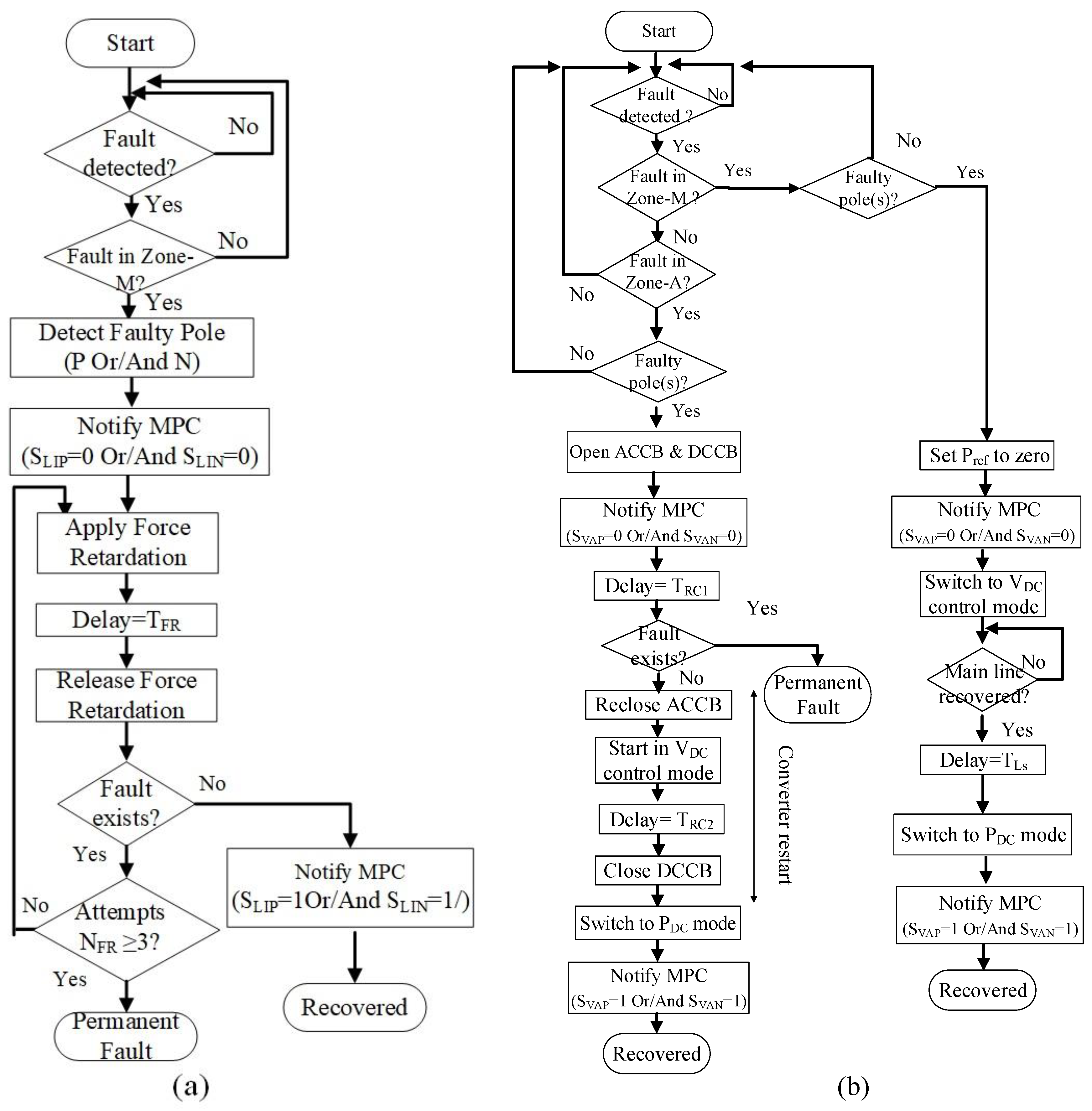
2.2. DC Side Fault Clearing Strategy

The proposed dc fault clearing procedure is shown in Figure 4.
In order to preserve the operation of the healthy pole during single-pole-to-ground faults, the fault recovery process is applied independently for positive and negative poles. As depicted in Figure 4a, upon detecting a fault in Zone-M, force retardation is applied to the respective pole(s) of the LCC rectifier. For example, if only P-pole is involved in the fault, SLIP in Equation (1) is reset (SLIP = 0) to notify the MPC of cease of power transmission in P-pole. After a fixed time delay TFR, which should be carefully selected by considering the worst case, the force retardation is released. If the voltage is recovering, SLIP is set (SLIP = 1) again and the firing angle of the LCC rectifier is gradually decreased to its pre-fault value. If the voltage does not recover in three attempts, the fault is declared as a permanent fault and the operation of LCC is stopped.
As depicted in Figure 4b, for a fault on the main transmission line, the dc CB of each faulted pole is disconnected immediately. Then the operating mode of the faulted poles of the VSC stations are changed to dc side voltage control mode till the fault is cleared. For a fault on a VSC branch, say on Zone-A as depicted in Figure 4b, the relevant dc CBs (dc CB on P-pole, N-pole, or both) are immediately opened to isolate the faulted pole(s) from the main transmission line. The IGBTs of the faulted pole of VSC-A (say P-pole) are immediately blocked by the converter internal protection. Subsequently, the faulted pole, P-pole in this case, is de-energized by opening the corresponding ac CB, and the MPC is notified about the de-energization by resetting SVAP (SVAP = 0).
Before enabling the reclose operation, a fixed delay of TRC1 is allowed to rule out the possibility that the fault is permanent because reclosing onto a fault is hazardous to converter IGBTs. This check may require communicating with protection IEDs [38,39,40,41]. Therefore communication delays should be taken into account in setting TRC1. The approach of determining the presence of a fault will be discussed later in Section 3.2. If the fault has been cleared, ac CB is reclosed and the operating mode of the relevant pole of VSC-A is changed from STATCOM mode to voltage control mode. The dc CB is reclosed once the converter terminal voltage reaches the dc voltage at tapping Point-A. Thereafter, the MPC is notified by setting SVAP (SVAP = 1) back to its normal value. The operating mode of P-pole of VSC-A is changed to PDC control mode and the pre-fault power reference is re-established. The same process is applied to N-pole or both poles of VSC-A depending on the fault type. The same procedure is applicable to VSC-B, for faults on Zone-B. More details of the grid energization procedure can be found in [6].

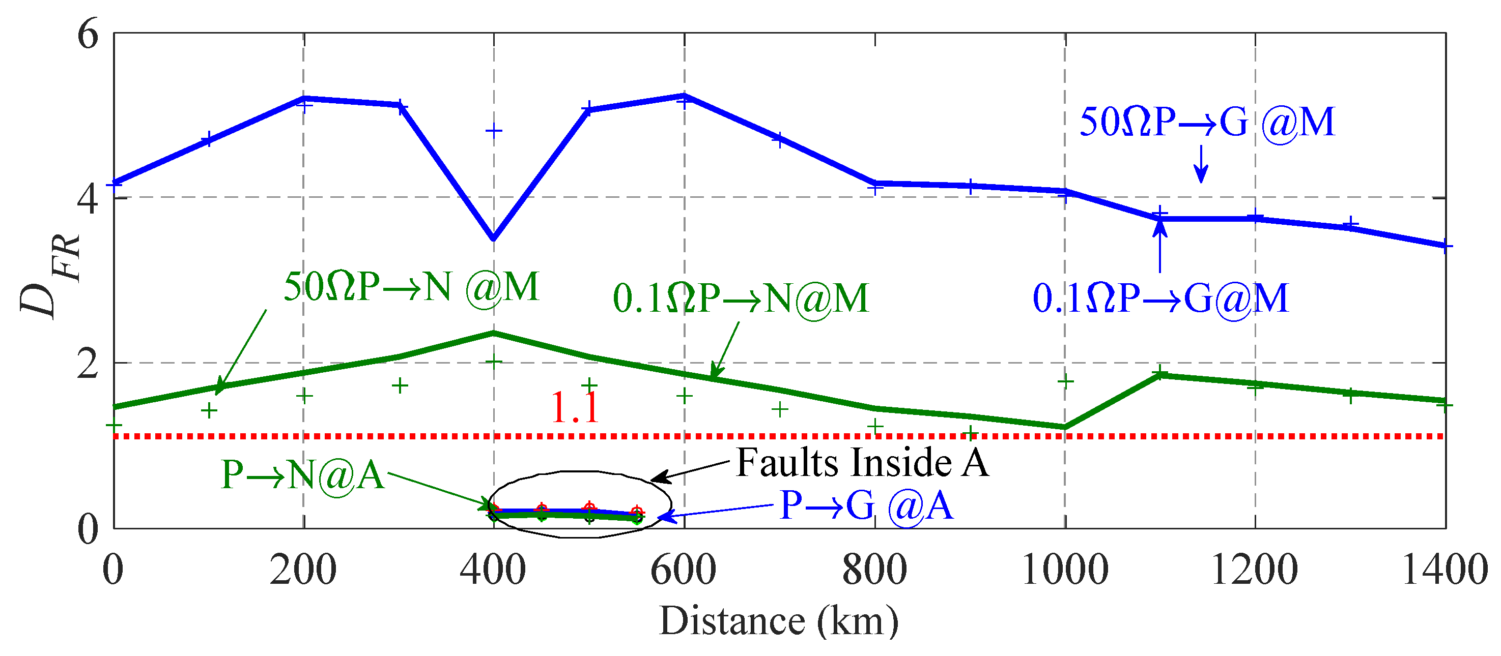
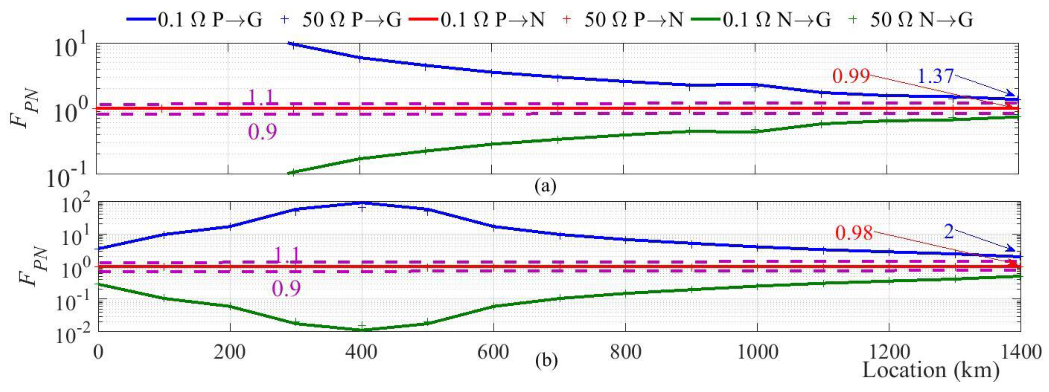
2.3. Fault Discrimination Strategy

As a breaker must isolate only the faulty pole(s) of the transmission line segment (protection zone) involved in the fault, a highly secure fault discrimination strategy is important to achieve the desired reliability improvement. The dc CBs separate the different protection zones and are associated with di/dt limiting inductors as shown in Figure 2. These inductors are referred to as the boundary inductors in this paper due to their location at the boundaries of adjacent protection zones. Due to the existence of a boundary inductor between the main transmission line and a VSC branch, during a fault on the main transmission line, the maximum rate of change of voltage (ROCOV) observed at any terminal of the main transmission line is significantly higher than the maximum ROCOV observed on any terminal of a VSC branch; the opposite is true during a fault on a VSC branch [27,38]. This enables discrimination of faults and therefore, maximum ROCOV is selected as the main fault indicator [27]. The sensitivity of the ROCOV based fault discrimination is improved by incorporating a directional logic as presented in [41] and using the aerial voltage components. The directional logic is employed only on IEDs -AM, -AI, -BM, and -BI. The directional logic is not relevant for IED-LR and IED-LI, since there are no other dc protection zones behind them. The faulty pole is identified using the logic described in [42]. The proposed fault discrimination algorithm with combined features is shown in Figure 5.
The algorithm is run on an IED located at the boundary of a protected line. An IED takes voltage measurements at either side of the boundary inductors of P- and N-poles, and the currents through the inductors on both poles as inputs. VLN, VLP, are respectively N-pole and P-pole voltages on line side of the boundary inductors and VBN, VBP are N-pole and P-pole voltages of the bus side of the boundary inductors. It then extracts the aerial components of the input voltages and the currents: V L α ( = V L P V L N ) , the aerial component of the voltages at the line side of boundary inductors, V B α ( = V B P V B N ) , the aerial component of the voltages at the bus side of the boundary inductors, and I L α ( = I P I N ) , the aerial component of the current. The currents IP and IN are respectively the currents through the P-pole and the N-pole.
The algorithm is triggered when any of the observed rate of change of current (ROCOC) value is greater than the threshold KT. The maximum values of ROCOV and ROCOC are tracked over a short time window, T w m a x , and the respective maximum values observed at the end of the time-window are sent to calculate the fault discrimination indices. Two indices, FPN and DFR, are calculated using Equations (2) and (3) using the maximum values of ROCOV and ROCOC.
D F R = Max ( d V L α / d t ) Max ( d V B α / d t )
F P N = Max ( d I P / d t ) Max ( d I N / d t )
If DFR is greater than a preset threshold (DFR > 1 + ε), the fault is declared to be on the forward side [41]. The faulty poles are identified by considering the fact that index FPN is close to unity for pole-to-pole faults (1 + ε > FPN ≥ 1 − ε), considerably greater than unity for P-pole-to-ground faults (FPN > 1 + ε), and considerably less than unity for N-pole-to-ground faults (1 − ε > FPN) [42]. ε is a positive tolerance value. Once the fault type is identified, depending on whether the fault is a single-pole fault or a pole-to-pole fault, the maximum rate of change of VF is compared with a threshold ( S _ R X Y p for pole-to-ground and S _ R X Y p p for pole-to-pole) to determine whether the fault is within the protected line.

3. Test System Parameters and Settings

A detailed electromagnetic transient simulation model of the power system shown in Figure 2 was implemented on the PSCAD/EMTDC simulation software to validate the effectiveness of the proposed fault detection and clearance scheme.

3.1. Test System

The test system is adapted from [1]. The LCC scheme considered in this study is similar to a Bipole II of the Nelson River HVdc system [37], including the transmission line parameters. The line lengths are shown in Figure 2. Each pole of the LCC stations is assumed to consisting of twelve pulse converters. The principle converter parameters and transformer data are given in Table 1 and Table 2 respectively.
A voltage-dependent current order limit (VDCOL) is implemented at the LCC inverter to protect its thyristor valves during ac side faults. The MMC cell capacitance is sized to achieve a ratio of 25 J/kVA [43] for the total capacitor stored energy in the converter to the rated power. The remaining parameters of the VSCs are given in [1]. A 60 mH inductor is placed at terminals of the VSC stations and in series with dc CBs. The dc CB operating delay and the maximum breaking current are assumed to be 2 ms and 6 kA. IGBTs are blocked when the current through any arm increased beyond 3 pu and for longer than 20 µs.

3.2. Protection Settings

In order to avoid false tripping, the single-pole ROCOV threshold setting S _ R X Y p for the IED-XY should be set higher than the observed maximum ROCOV for a single-pole-to-ground short circuit fault in the forward direction, just outside the protected zone demarcated by the terminal inductor. This value is denoted by R O C O V p M x _ A . Furthermore, in order to make sure far-end faults are detected, S _ R X Y p should be set lower than the observed maximum ROCOV value for a high resistance single-pole-to-ground fault at the far-end of the protected transmission line, R O C O V p M x _ B . The expected maximum fault resistance to be detected should be selected by considering the constraint R O C O V p M x _ B > R O C O V p M x _ A . Therefore, to compromise the sensitivity and the reliability requirements, the single-pole-to-ground fault ROCOV threshold setting for IED-XY is calculated with Equation (4).
S _ R X Y p = 1 2 ( R O C O V p M x _ A + R O C O V p M x _ B )
The pole-to-pole settings are calculated in a similar manner by considering the pole-to-pole faults instead of the single-pole-to-ground faults. The setting S _ R X Y p p for pole-to-pole faults is greater than the threshold settings for single-pole faults, S _ R X Y p . Table 3 shows the maximum ROCOV values used to determine the settings S _ R X Y p p and S _ R X Y p . The maximum ROCOV settings of protection IEDs, S _ R X Y p p and S _ R X Y p , are given in Table 4.
The threshold settings for the directional discrimination index, DFR, and the faulty pole(s) identification index, FPN, were selected considering a 10% tolerance and common for all IEDs. The ideal value for these two indices is 1, and the 10% tolerance provides an added security. Based on the simulation studies, the fault detection threshold parameter KT is set to 2 kA/ms and the time window for computing the maximum ROCOC and ROCOV values, T w m a x , was set to 0.5 ms. This is the expiry time of the timer shown in Figure 5.
When selecting the time delay, TRC1, the expected maximum fault clearing time and the time to run an appropriate checking mechanism to determine whether a fault on a VSC branch is permanent or temporary should be considered. The discrimination between a temporary arc fault and a permanent fault can be done in two ways in this application. The extinction of a temporary arc can be confirmed by looking at the reflected wave after injecting an active signal with the help of VSC, as proposed in [44,45]. Alternatively, the temporary faults can be discriminated from the permanent faults with the help of residual voltage characteristics of dc CBs at the tapping point as proposed in [38,39,40,41]. According to [38,41], the temporary faults can be discriminated from the permanent faults within a several tens of milliseconds. Assuming that the confirmation of extinction of fault is done at the dc CB, the time required to assess and inform the converter station are considered. The communication delay is estimated assuming that the velocity of signal propagation is 150 km/ms. The time delay, Tdel, for communication between two entities separated by l km distance, is approximated by Equation (5).
T d e l = l 150 + 1   m s
The time delay TRC1 shown in Figure 4b is set to 362 ms by considering a 330 ms duration for extinction of the temporary fault, a 30 ms worst-case delay for confirmation of the extinction of the temporary fault, and 2 ms communication delay. The time delay TFR shown in Figure 4a is set to 150 ms. The delay TRC2 is the time delay to settle the VSC-A terminal voltage once it is re-started in DC voltage control mode by de-blocking the IGBT after re-closing AC circuit breakers. TRC2 is set to 50 ms.

4. Results

4.1. Fault Discrimination

Determination of the fault direction using the calculated value of DFR at IED-AM is demonstrated in Figure 6 for faults inside Zone-M and Zone-A.
To avoid the ambiguity of having two curves for the same location, the distance to a fault is measured from the LCC rectifier end. The label 0.1ΩP→G@M indicates a P-pole-to-ground fault inside Zone-M simulated with a 0.1 Ω fault resistance and 0.1ΩP→N@M indicates a P-pole-to-N-pole fault with a 0.1 Ω fault resistance. The same convention is used for 50 Ω faults. The respective threshold is also indicated on each graph. As depicted in Figure 6, the minimum calculated DFR for the faults inside Zone-M is 1.2 whereas the highest calculated value of DFR for faults inside Zone-A is 0.24. Therefore, as per the directional criterion depicted in Figure 6, any fault inside Zone-A is discriminated as a reverse fault at IED-AM while any fault inside Zone-M is declared as a fault in the forward direction. As depicted in Figure 7a,b, pole(s) involved in the fault can be recognized with the help of faulty pole(s) identification criterion respectively at IED-LR at the LCC rectifier and IED-AM at the tapping point-A.
All P-pole-to-N-pole faults result in FPN values between the thresholds 0.9 and 1.1; FPN values for all P-pole-to-ground faults are above 1.1; and FPN values for all N-pole-to-ground faults are below 0.9. Similar observations were made for the protection IEDs located near the LCC inverter and Point-B. The minimum margin of discrimination of faulty pole(s) at IED-A is 82%, and despite the extreme line length, IED-LR manages to recognize the faulty pole even for remote faults. As depicted in Figure 8a,b, the maximum ROCOV is greater than the respective thresholds up to a fault resistance of 50 Ω.
The discrimination margin for end of line faults is higher for pole-to-pole faults (15%) when compared with the single pole-to-ground faults (5%). If a higher margin is desired for single-pole-to-ground faults, the fault resistance considered in measurement of R O C O V p M x _ B that is used in Equation (4) can be lowered, leaving the end of line high resistance faults to be dealt using a transfer trip scheme or a line differential type backup protection scheme. Clearing time is not critical for such faults as the current rises slower and the peak fault current is lower for remote high resistance faults. As depicted in Figure 7, pole(s) involved in the fault can be identified using FPN with an adequate margin even though the line is very long. Similar observations were made for the protection IED located near the LCC inverter. Furthermore, as depicted in Figure 8c, the faulty section can be identified using the maximum ROCOV criterion with ample margin for both pole-to-pole (46%) and single-pole-to-ground (43%) faults at IED-AM. The variation of maximum ROCOV for N-pole-to-ground faults is similar to that of P-pole-to-ground faults.
Therefore, the results presented in Figure 6, Figure 7 and Figure 8 confirm the ability of protection IEDs located at LCC stations and tapping points to identify any fault in Zone-M having a resistance up to 50 Ω, and the pole(s) involved. Furthermore, settings calculated using Equation (4) avoids false tripping for any fault in the forward direction beyond the protected zones.
The results shown in Table 5 confirm the capability of IED at the tapping point-A to detect and discriminate the faults on Zone-A using the proposed fault discrimination criteria. In Table 5, distance to the fault is measured from the IED. The third and fourth columns indicate the maximum ROCOV value for a metallic fault and for a 50 Ω fault at the specified location.

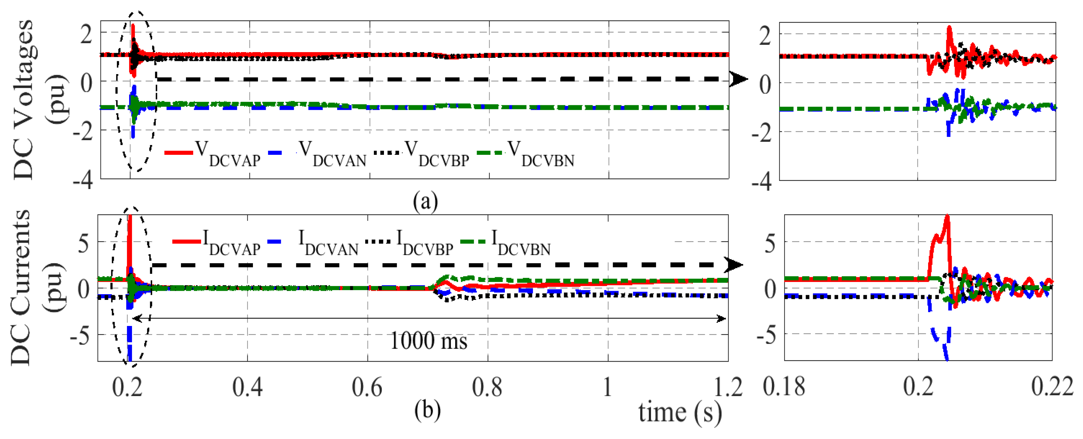
4.2. Clearing Temporary Faults on the Main Line

In the following simulation studies, a temporary metallic fault was considered and the fault is assumed to be self-cleared when the current through the fault falls below 0.1 kA.

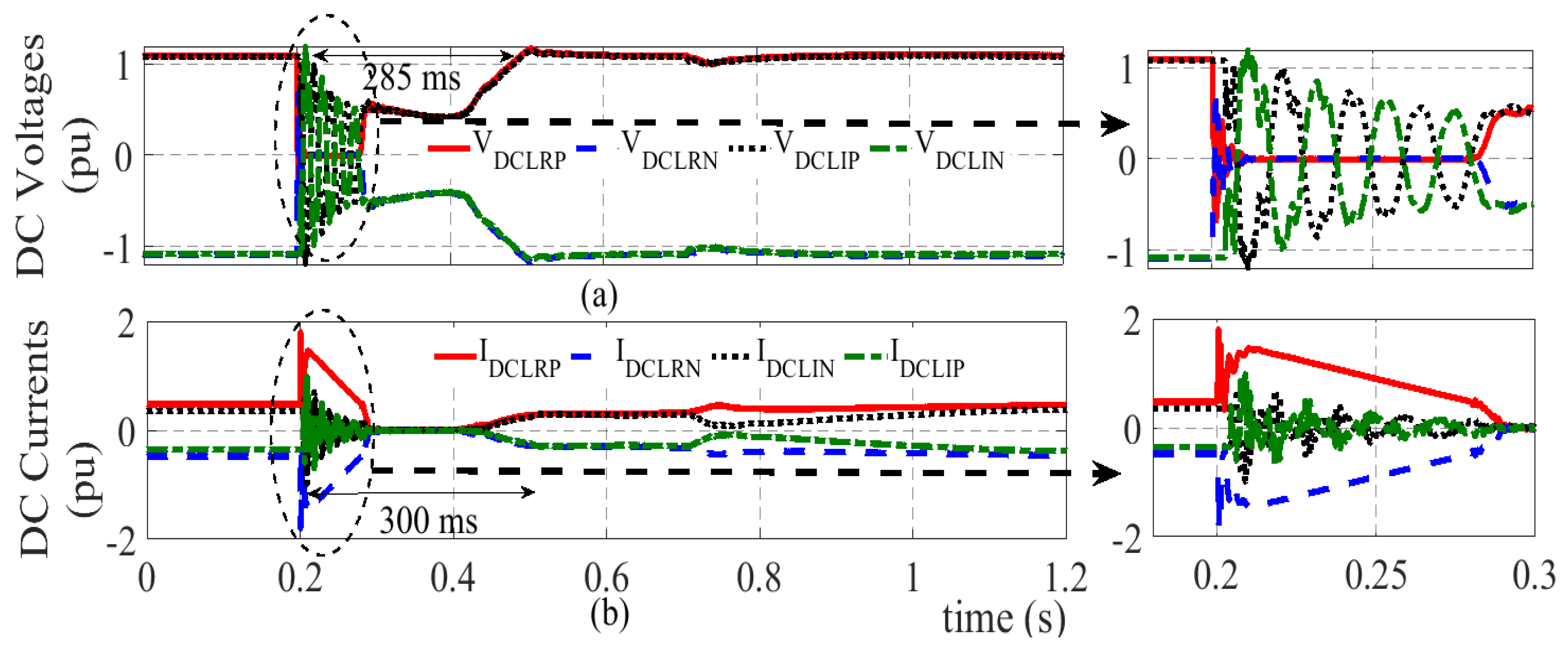
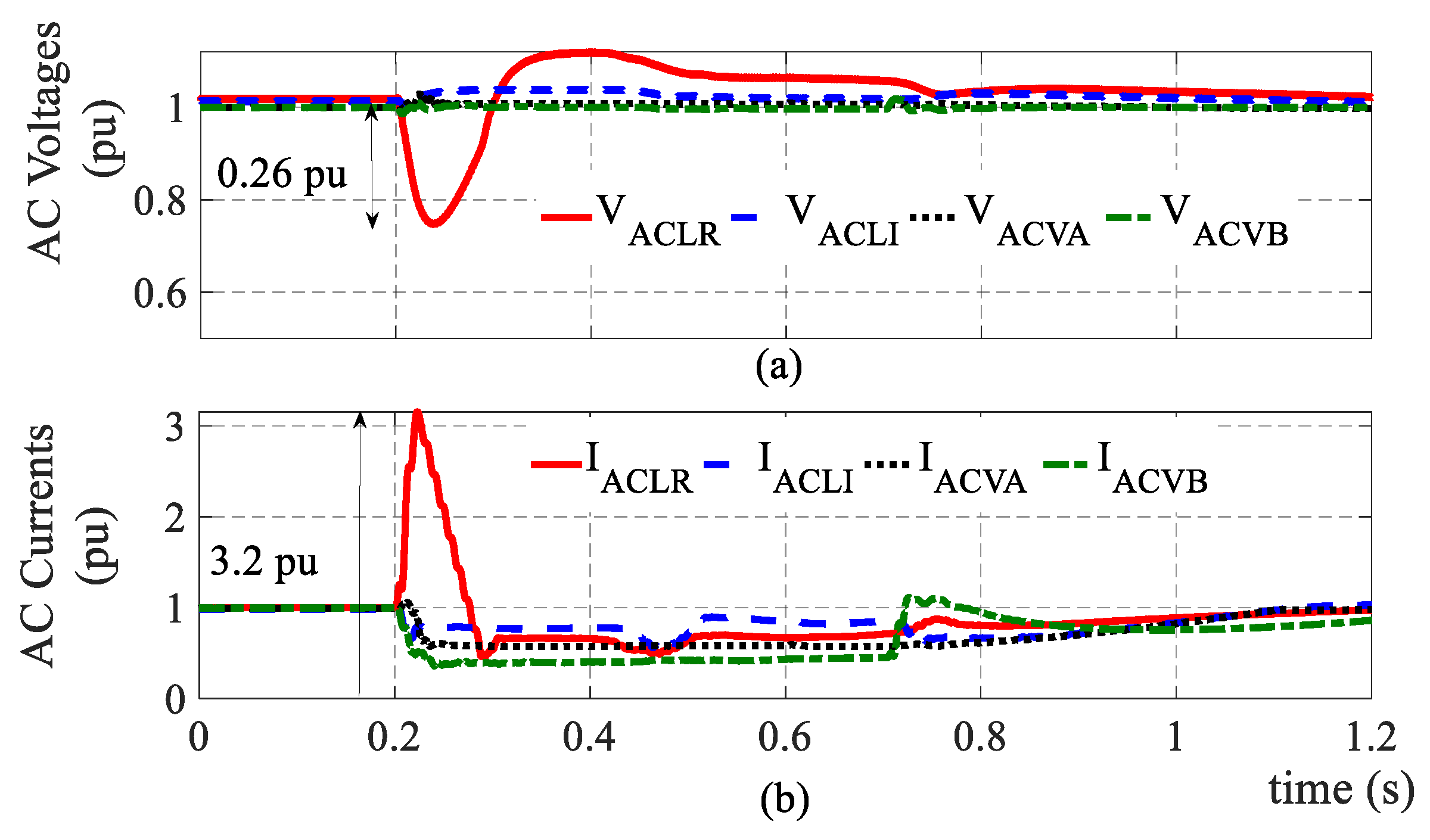
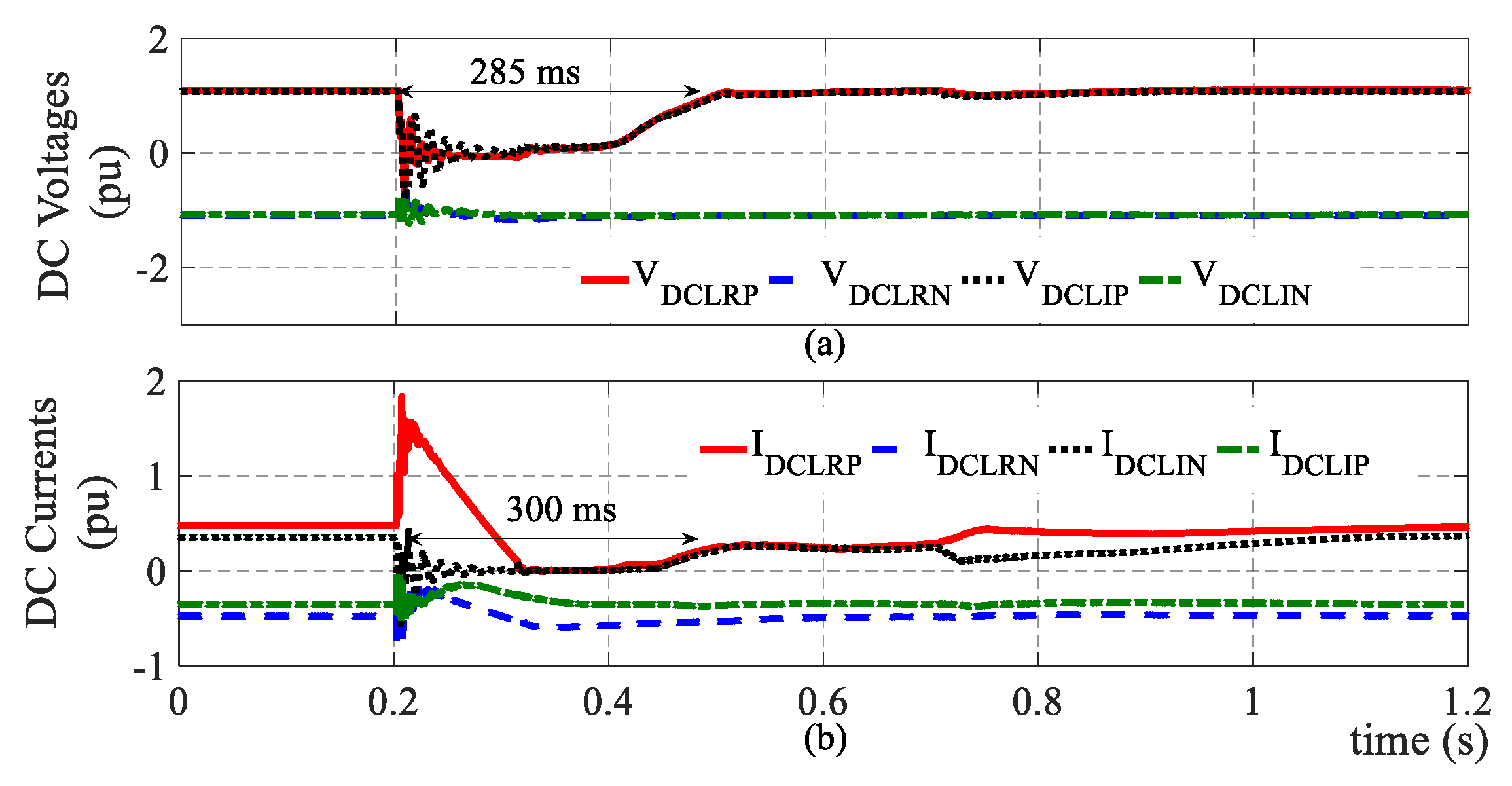
4.2.1. Pole-to-Pole Faults

Figure 9 and Figure 10 show the dc voltages and currents observed at the VSC and LCC stations during a P-pole-to-N-pole fault on the main transmission line, 100 km away from the LCC rectifier.
According to Figure 9, the fault currents through the VSC rectifiers rapidly rose after the fault, until the dc CBs are opened as per the procedure described in the flowchart of Figure 4. Operation of the dc CBs quickly eliminated the fault current contributions from the VSCs, and enabled clearing of this temporary fault through force retardation of LCCs. This can be seen from Figure 10.
Moreover, Figure 9 shows that both VSCs managed to hold the dc voltage operating in the dc voltage control mode, fulfilling the requirement 2 listed in Section 2, and then quickly reconnect to the main transmission line after its restoration. As depicted in Figure 11, only the ac system connected to the LCC rectifier is noticeably affected by the fault.
In contrast to the topology without dc CB studied in [1], the ac system connected to the VSC rectifier was not affected by the fault. A 0.26 pu drop in ac voltage at LCC rectifier was due to 3.2 pu rise in ac current during the fault.
According to Figure 10, the fault clearing time, voltage recovery time, and the pre-fault state recovery times for the LCC link are 120 ms, 285 ms, and 300 ms. These figures are much shorter than those achievable with the topology without dc CB proposed in [1], i.e., 300 ms, 700 ms, and 1000 ms respectively. Without dc CBs, the VSC rectifier injects fault currents for several ac cycles until the ac CB opens and interrupts the VSC [1]. Furthermore, the VSC rectifier needs restarting and regaining control to restore the pre-fault power level of VSC stations, and this complete process required about 1000 ms as per [1].

4.2.2. Pole-to-Ground Faults

The single-pole-to-ground fault recovery performance was studied considering a metallic P-pole-to-ground fault on the main transmission line, 700 km away from the LCC rectifier. As per the results shown in Figure 12 and Figure 13, strong transients are visible in healthy pole voltages and currents observed at both LCC and VSC stations.
After applying the fault recovery process in Figure 4, the voltages and currents of the healthy pole become stable within about 200 ms. As visible in Figure 14, the drop in ac side voltage of the LCC rectifier is smaller than that for the pole-to-pole fault.
Therefore, as depicted in Figure 15, power can be transferred through the healthy pole during a single-pole-to-ground fault. In addition to the recovery speed, the capability of transferring power through the healthy pole of VSC stations is another advantage of the proposed scheme when compared with the scheme without dc CB in [1].

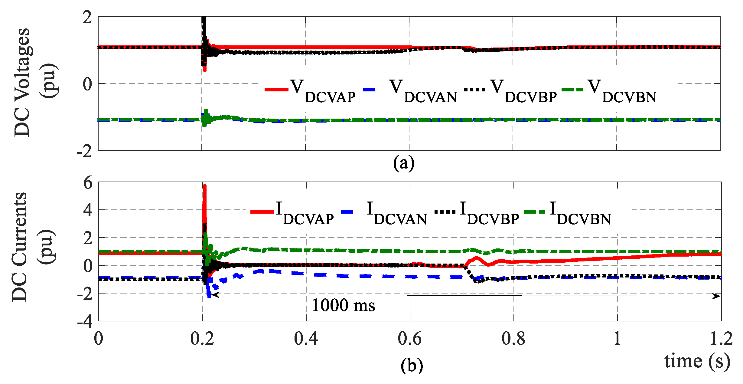
4.3. Clearing Temporary Faults on a VSC Branch

4.3.1. Pole-to-Pole Faults

Figure 16 and Figure 17 show the dc side measurements at converter stations for a metallic pole-to-pole fault on VSC branch-A, 50 km away from VSC-A (in Zone-A).
According to Figure 16, the LCC link was not impacted and the requirement 1 listed in Section 2.1 was fulfilled. The fault recovery process of VSC-A is depicted in Figure 17. Note that this momentary peak fault current of 10.5 kA fed by VSC-A is shared by all three arms of the VSC. It took about 1000 ms to restore the pre-fault state. The only significant effect on the LCC link was the reduction of power received to LCC inverter due to the sudden disconnection of VSC-A (rectifier). However, the amount of power delivered to the LCC inverter was restored to the pre-fault level within 1000 ms.

4.3.2. Pole-to-Ground Faults

Recovering from asymmetrical faults is more challenging. However, the successful application of the fault recovery procedure proposed in Figure 4 to recover from a single-pole-to-ground fault on VSC branch-A (Zone-A) is depicted in Figure 18 and Figure 19. The healthy pole of VSC-A is capable of continuing the power transfer with ground return mode till the fault is recovered.

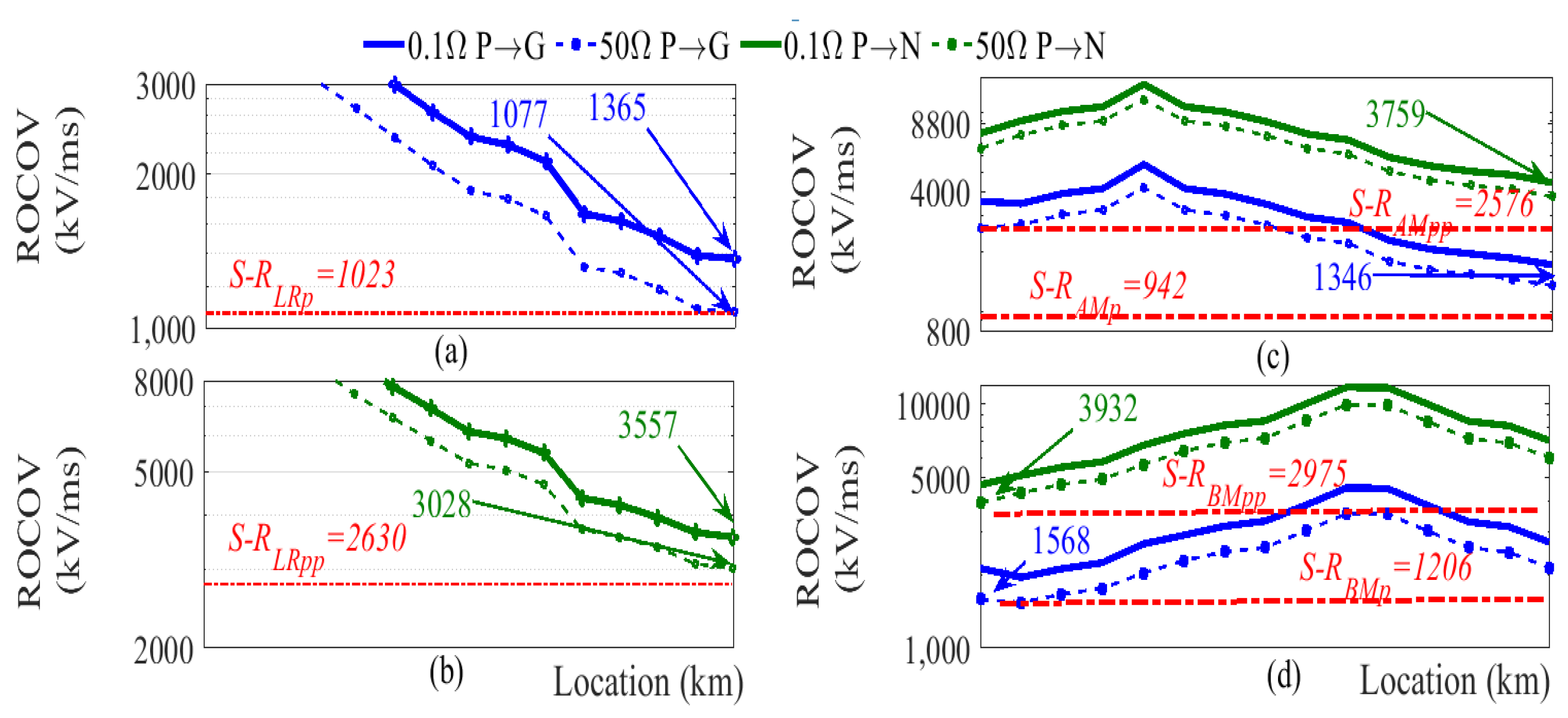
4.4. Fault Recovery Delays, Fault Detection Speed, and Breaker Rating

The observed recovery times for four-fault scenarios are tabulated in Table 6. The first and second columns show respectively the fault zone and fault type. The third and the fourth columns show the time taken to regain the pre-fault power level for the LCC link and for the VSC station connected to the faulted VSC branch.
As depicted in Figure 20a, any metallic fault can be detected within 1.09 ms. The pole-to-pole faults on the main transmission line are detected a little faster than single pole-to-ground faults, and this is more desirable. Figure 20b shows the observed maximum fault current through the dc CBs, 2 ms after the fault. Accordingly, a dc CB capable of interrupting 6 kA within 2 ms is adequate for the considered hybrid HVdc system.

5. Conclusions

A selective fault clearing scheme is proposed for a possible hybrid VSC-LCC multi-terminal HVdc transmission structure in which the spare capacity of an LCC transmission line is shared with a smaller VSC scheme. This situation exists on the present-day Bipoles I and II of Manitoba Hydro’s HVdc transmission system. The proposed fault discrimination and fault clearing procedure allow tapping of the main LCC link without significant degradation of the fault recovery performances. This is achieved with an optimal way by placing a dc CB on each VSC branch at the point of interconnection to the main transmission line. The detailed simulations with a test system confirmed (i) the ability of successfully discriminating faults at different sections at a speed fast enough for successful fault recovery, (ii) the ability to identify the faulted pole(s) to enable single-pole operation during the single-pole-to-ground faults, (iii) the successful recovery from temporary faults at various locations, and (iv) the requirements are within the capability of a 6 kA, 2 ms dc CB, for the test system considered.

Author Contributions

Conceptualization, N.M.H., A.D.R., A.M.G., and I.T.F.; Methodology, N.M.H. and A.D.R.; Validation, N.M.H., A.D.R., A.M.G., and I.T.F.; Draft preparation, N.M.H. and A.D.R.; Review and Editing, N.M.H., A.D.R., A.M.G., and I.T.F.; Supervision, A.D.R. and A.M.G.; Project administration, A.D.R.; Funding Acquisition, A.D.R. and I.T.F. All authors have read and agreed to the published version of the manuscript.

Funding

This work is financially supported by Manitoba Hydro, Manitoba, Canada, and Mitacs Accelerate funding program, Canada.

Conflicts of Interest

The authors declare no conflict of interest.

References

  1. Haleem, N.M.; Rajapakse, A.D.; Gole, A.M.; Fernando, I.T. Investigation of Fault Ride-Through Capability of Hybrid VSC-LCC Multi-Terminal HVdc Transmission Systems. IEEE Trans. Power Deliv. 2019, 34, 241–250. [Google Scholar] [CrossRef]
  2. Flourentzou, N.; Agelidis, V.G.; Demetriades, G.D. VSC-based HVdc power transmission systems: An overview. IEEE Trans. Power Electron. 2009, 24, 592–602. [Google Scholar] [CrossRef]
  3. Tang, G.; Xu, Z. A LCC and MMC hybrid HVdc topology with DC line fault clearance capability. Int. J. Electr. Power Energy Syst. 2014, 62, 419–428. [Google Scholar] [CrossRef]
  4. Hahn, C.; Geuß, A.; Luther, M. Modeling and control design of hybrid—LCC and VSC based—HVdc systems. In Proceedings of the IEEE/PES Transmission and Distribution Conference and Exposition (T&D), Dallas, TX, USA, 2–5 May 2016. [Google Scholar]
  5. Nguyen, M.H.; Saha, T.K.; Eghbal, M. Hybrid multi-terminal LCC HVdc with a VSC Converter: A case study of Simplified South East Australian system. In Proceedings of the IEEE Power and Energy System General Meeting, San Diego, CA, USA, 22–26 July 2012. [Google Scholar]
  6. Naushath, M.H.; Rajapakse, A.D.; Gole, A.M.; Fernando, I.T. Energization and regulation of a hybrid HVdc grid with LCC and VSC. In Proceedings of the IEEE Electric Power and Energy Conference, Saskatoon, SK, Canada, 22–25 October 2017. [Google Scholar]
  7. Liao, J.; Zhou, N.; Wang, Q.; Luo, Y. A Bypass LCC-Based dc Fault Isolation Scheme for Bipolar MMC–HVdc. IEEE Access 2019, 7, 118218–118228. [Google Scholar]
  8. Lin, W.; Wen, J.; Yao, M.; Wang, S.; Cheng, S.; Li, N. Series VSC-LCC converter with self-commutating and dc fault blocking capabilities. In Proceedings of the IEEE PES General Meeting, National Harbor, MD, USA, 27–31 July 2014. [Google Scholar]
  9. Rao, H.; Zhou, Y.; Xu, S.; Cai, X.; Cao, W.; Xu, Y.; Ren, C. Key technologies of ultra-high voltage hybrid LCC-VSC MTdc systems. CSEE J. Power Energy 2019, 5, 365–373. [Google Scholar] [CrossRef]
  10. Lee, Y.; Cui, S.; Kim, S.; Sul, S.K. Control of hybrid HVdc transmission system with LCC and FB-MMC. In Proceedings of the IEEE Energy Conversion Congress and Exposition, Pittsburgh, PA, USA, 14–18 September 2014. [Google Scholar]
  11. Torres, O.R.E.; Molinas, M.; Undeland, T. Hybrid HVDC connection of large offshore wind farms to the AC grid. In Proceedings of the IEEE International Symposium on Industrial Electronics, Hangzhou, China, 28–31 May 2012. [Google Scholar]
  12. Pan, W.; Chang, Y.; Chen, H. Hybrid Multi-terminal HVdc System for Large Scale Wind Power. In Proceedings of the IEEE PES Power Systems Conference and Exposition, Atlanta, GA, USA, 29 October–1 November 2006. [Google Scholar]
  13. Jung, J.; Cui, S.; Lee, J.; Sul, S. A New Topology of Multilevel VSC Converter for a Hybrid HVdc Transmission System. IEEE Trans. Power Electron. 2017, 32, 4199–4209. [Google Scholar] [CrossRef]
  14. Li, G.; Liang, J.; Joseph, T.; An, T.; Lu, J.; Szechtman, M.; Andersen, B.R.; Zhuang, Q. Feasibility and Reliability Analysis of LCC dc Grids and LCC/VSC Hybrid dc Grids. IEEE Access 2019, 7, 22445–22456. [Google Scholar] [CrossRef]
  15. Xu, D.; Zhao, X.; Lu, Y.; Qin, K.; Guo, L. Study on overvoltage of hybrid LCC-VSC-HVdc transmission. J. Eng. 2019, 16, 1906–1910. [Google Scholar] [CrossRef]
  16. Howell, S.; Filizadeh, S.; Gole, A.M. Unidirectional HVdc topology with dc fault ride-through capability. Can. J. Electr. Comput. Eng. 2017, 40, 41–49. [Google Scholar]
  17. Annakkage, U. Hybrid LCC and Multi-terminal Full-Bridge Modular Multi-Level Converters for HVdc Transmission. Master’s Thesis, University of Toronto, Toronto, ON, Canada, 2015. [Google Scholar]
  18. Torres, O.R.E.; Molinas, M.; Undeland, T. Offshore Wind Farm Grid Integration by VSC Technology With LCC-Based HVdc Transmission. IEEE Trans. Sustain. Energy 2012, 3, 899–907. [Google Scholar] [CrossRef]
  19. Nguyen, M.H.; Saha, T.K.; Eghbal, M. Investigation on the impact of hybrid multi-terminal HVdc system combining LCC and VSC technologies using system identification. In Proceedings of the Australasian Universities Power Engineering Conference, Bali, Indonesia, 26–29 September 2012. [Google Scholar]
  20. Song, J. Analysis of Hybrid LCC-VSC HVdc Transmission Systems. Master’s Thesis, Universitat Politècnica de Catalunya UPC, Barcelona, Spain, 2018. [Google Scholar]
  21. Xiao, L.; Li, Y.; Xiao, H.; Zhang, Z.; Xu, Z. Electromechanical Transient Modeling of Line Commutated Converter-Modular Multilevel Converter-Based Hybrid Multi-Terminal High Voltage Direct Current Transmission Systems. Energies 2018, 11, 2102. [Google Scholar] [CrossRef] [Green Version]
  22. Suriyaarachchi, D.H.R.; Karawita, C.; Mohaddes, M. Tapping existing LCC-HVdc systems with Voltage Source Converters. In Proceedings of the IEEE Power and Energy Society General Meeting, Boston, MA, USA, 17–21 July 2016. [Google Scholar]
  23. Li, X.; Yuan, Z.; Fu, J.; Wang, Y.; Liu, T.; Zhu, Z. Nanao multi-terminal VSC-HVdc project for integrating large-scale wind generation. In Proceedings of the IEEE Power and Energy General Meeting, National Harbor, MD, USA, 27–31 July 2014. [Google Scholar]
  24. Jie, Z.; Haibin, L.; Rui, X.; Wenhai, N.; Kun, S.; Feiyang, H. Research of dc circuit breaker applied on Zhoushan multi-terminal VSC-HVdc project. In Proceedings of the IEEE PES Asia-Pacific Power and Energy Engineering Conference, Xi’an, China, 25–28 October 2016. [Google Scholar]
  25. Li, X.; Song, Q.; Liu, W.; Rao, H.; Xu, S.; Li, L. Protection of Nonpermanent Faults on dc Overhead Lines in MMC-Based HVdc Systems. IEEE Trans. Power Deliv. 2013, 28, 483–490. [Google Scholar] [CrossRef]
  26. Häfner, J.; Jacobson, B. Proactive Hybrid HVDC breakers—A key innovation for Reliable HVdc grid. In Proceedings of the CIGRE Symposium, Bologna, Italy, 13–15 September 2011. [Google Scholar]
  27. Sneath, J.; Rajapakse, A.D. Fault Detection and Interruption in an Earthed HVdc Grid Using ROCOV and Hybrid DC Breakers. IEEE Trans. Power Deliv. 2016, 31, 973–981. [Google Scholar] [CrossRef]
  28. Li, R.; Xu, L.; Yao, L. DC Fault Detection and Location in Meshed Multiterminal HVdc Systems Based on DC Reactor Voltage Change Rate. IEEE Trans. Power Deliv. 2017, 32, 1516–1526. [Google Scholar] [CrossRef] [Green Version]
  29. Sneath, J.; Rajapakse, A.D. DC Fault Protection of a Nine-Terminal MMC HVdc Grid. In Proceedings of the IET International Conference on AC and DC Power Transmission, Birmingham, UK, 10–12 February 2015. [Google Scholar]
  30. Nanayakkara, O.M.K.K.; Rajapakse, A.D.; Wachal, R. Location of DC Line Faults in Conventional HVdc Systems With Segments of Cables and Overhead Lines Using Terminal Measurements. IEEE Trans. Power Deliv. 2012, 27, 279–288. [Google Scholar] [CrossRef]
  31. Cheng, S.; Wang, Y.; Zhang, B.; Ma, H. Applicability analysis of travelling wave protection for the hybrid HVDC system. J. Eng. 2019, 16, 1730–1736. [Google Scholar] [CrossRef]
  32. Gao, S.; Zhu, H.; Niu, D.; Zhang, B.; Song, G. A Transient Power Protection Principle for Hybrid Bipolar DC Transmission Line Based on LCC-HVdc and VSC-HVdc. In Proceedings of the International Conference on Power System Technology, Guangzhou, China, 6–8 November 2018. [Google Scholar]
  33. Wang, Y.; Zhang, B. A novel hybrid directional comparison pilot protection scheme for the LCC-VSC hybrid HVdc transmission lines. In Proceedings of the 13th International Conference on Development in Power System Protection (DPSP), Edinburgh, UK, 7–10 March 2016. [Google Scholar]
  34. Wang, Y.; Zhang, B. Backward travelling wave-variation-based protection for the transmission line of a hybrid HVdc system. J. Eng. 2019, 2019, 1261–1265. [Google Scholar] [CrossRef]
  35. Wang, D.; Hou, M.; Gao, M.; Qiao, F. Travelling wave directional pilot protection for hybrid LCC-MMC-HVdc transmission line. Int. J. Electr. Power Energy Syst. 2020, 115, 105431. [Google Scholar] [CrossRef]
  36. Chen, X.; Li, H.; Liang, Y.; Wang, G. A protection scheme for hybrid multi-terminal HVdc networks utilizing a time-domain transient voltage based on fault-blocking converters. Int. J. Electr. Power Energy Syst. 2020, 115, 105825. [Google Scholar] [CrossRef]
  37. Thio, C.V. Nelson River HVdc Bipole-Two Part I—System Aspects. IEEE Trans. Power Appar. Syst. 1979, 98, 165–173. [Google Scholar] [CrossRef]
  38. Li, B.; He, J.; Li, Y.; Wen, W. A Novel dc CB Reclosing Strategy for the Flexible HVDC Grid. IEEE Trans. Power Deliv. 2020, 35, 244–257. [Google Scholar] [CrossRef]
  39. Fan, X.; Zhang, B. DC line soft reclosing sequence for HVdc grid based on hybrid dc breaker. J. Eng. 2019, 16, 1095–1099. [Google Scholar] [CrossRef]
  40. Li, B.; Cui, H.; Li, B.; Wen, W.; Dai, D. A permanent fault identification method for single-pole grounding fault of overhead transmission lines in VSC-HVdc grid based on fault line voltage. Int. J. Electr. Power Energy Syst. 2020, 117, 105603. [Google Scholar] [CrossRef]
  41. Haleem, N.M.; Rajapakse, A.D. Application of New Directional Logic to Improve dc Side Fault Discrimination for High Resistance Faults in HVDC Grids. J. Mod. Power Syst. Clean Energy 2017, 5, 560–573. [Google Scholar] [CrossRef] [Green Version]
  42. Haleem, N.M.; Rajapakse, A.D. Fault Type Discrimination in HVdc Transmission Lines Using Rate of Change of Local Currents. IEEE Trans. Power Deliv. 2020, 35, 117–129. [Google Scholar] [CrossRef]
  43. Zygmanowski, M.; Grzesik, B.; Nalepa, R. Capacitance and inductance selection of the modular multilevel converter. In Proceedings of the Power Electronics and Applications, Lille, France, 2–6 September 2013. [Google Scholar]
  44. Wang, T.; Song, G.; Hussain, K.S.T. Adaptive Single-Pole Auto-Reclosing Scheme for Hybrid MMC-HVdc Systems. IEEE Trans. Power Deliv. 2019, 34, 2194–2203. [Google Scholar] [CrossRef]
  45. Wang, T.; Song, G.; Wu, L.; Wei, H.; Guang, S.; Chao, L. Novel reclosure scheme of MMC-HVdc system based on characteristic signal injection. J. Eng. 2019, 16, 1153–1157. [Google Scholar] [CrossRef]
Figure 1. Proposed protection design for hybrid VSC-LCC system in [1].
Energies 13 03554 g001
Figure 2. Hybrid VSC-LCC transmission system with two VSCs connected to an LCC-HVdc link.
Energies 13 03554 g002
Figure 3. Dc voltage measurement conditioning (illustrated for LCC inverter P-pole).
Energies 13 03554 g003
Figure 4. The fault recovery process, (a) at LCC rectifier station, (b) at VSC-A station (the same procedure is used at VSC-B station).
Energies 13 03554 g004
Figure 5. Fault discrimination algorithm.
Energies 13 03554 g005
Figure 6. Calculated DFR for faults inside Zone-M and Zone-A at IED-AM.
Energies 13 03554 g006
Figure 7. Calculated FPN for faults in Zone-M (a) At IED-LR, (b) At IED-AM.
Energies 13 03554 g007
Figure 8. Calculated maximum ROCOV values (a) At IED-LR for P-pole-to-ground faults, (b) At IED-LR for P-pole-to-N-pole faults, (c) At IED-AM, (d) At IED-BM.
Energies 13 03554 g008
Figure 9. DC side measurements at VSC stations for a P-Pole-to-N-Pole fault on the main transmission line (a) voltages, (b) currents.
Energies 13 03554 g009
Figure 10. DC side measurements at LCC stations for a P-Pole-to-N-Pole fault on the main transmission line (a) voltages, (b) currents. Shown to the right of each plot is a zoomed view of the initial transient period.
Energies 13 03554 g010
Figure 11. AC side measurements during P-Pole-to-N-Pole fault on the main transmission line (a) voltages, (b) currents.
Energies 13 03554 g011
Figure 12. DC measurements at LCC stations for a P-Pole-to-ground fault on main transmission line (a) voltages, (b) currents.
Energies 13 03554 g012
Figure 13. DC measurements at VSC stations for a P-Pole-to-ground fault on main transmission line (a) voltages, (b) currents.
Energies 13 03554 g013
Figure 14. AC side measurements for a P-Pole-to-ground fault on the main transmission line (a) voltages, (b) currents.
Energies 13 03554 g014
Figure 15. DC power for a P-Pole-to-ground fault on the main transmission line.
Energies 13 03554 g015
Figure 16. DC side measurements at LCC stations for a P-Pole-to-N-Pole fault on VSC branch-A (a) voltages, (b) currents.
Energies 13 03554 g016
Figure 17. DC side measurements at VSC stations for a P-Pole-to-N-Pole fault on VSC branch-A (a) voltages, (b) currents.
Energies 13 03554 g017
Figure 18. DC side measurements at VSC stations during a P-Pole-to-ground fault on VSC branch-A (a) voltages, (b) currents.
Energies 13 03554 g018
Figure 19. DC power measurements during a P-Pole-to-ground fault on VSC branch-A.
Energies 13 03554 g019
Figure 20. DC CB requirement (a) Fault detection speed, (b) Maximum dc CB current.
Energies 13 03554 g020
Table 1. Test system details.
ParameterValueUnits
Nominal dc Voltage±500kV
ac Sys. SCR LCC-Rectifier2.9
ac Sys. SCR LCC-Inverter5.0
ac Sys. SCR VSC-A/B3.0
Power ramping rate in LCC during fault recovery (per pole)1000MW/s
Power ramping rate in VSC during fault recovery (per pole)300MW/s
VSC Data
MMC cell capacitance2000µF
MMC cell switch on resistance0.2
Arm reactor25mH
Table 2. Transformer data.
ParameterValueUnits
MVA-LCCs 600 × 2MW/pole
MVA-VSC-A/B300MW/pole
Leakage Reactance-LCCs0.15pu
Leakage Reactance-VSCs0.1pu
Transformer Ratio LCCs230 kV/209 kV
Transformer Ratio VSCs330 kV/315 kV
Table 3. Maximum ROCOV values used with Equation (4).
IED R O C O V p p M x _ A (kV/ms) R O C O V p p M x _ B (kV/ms) R O C O V p M x _ A (kV/ms) R O C O V p M x _ B (kV/ms)
IED-LR223030289711077
IED-LI141329035861068
IED-AM139437595381346
IED-BM201939328751538
Table 4. Relay settings.
IED S _ R X Y p p (kV/ms) S _ R X Y p (kV/ms)IED S _ R X Y p (kV/ms) S _ R X Y p p (kV/ms)
IED-LR26301023IED-BM29751206
IED-LI2158827IED-AI85183542
IED-AM2576942IED-BI88383663
Table 5. Identifying faults in Zone-A at RAI.
Loc. (km)Fault Type R O C O V M a x 1 (kV/ms) R O C O V M a x 2 (kV/ms)DFRFPN
100P→G739357979.511.9
50P→G8518668210.456.6
100P→N19,03516,0309.41
50P→N22,05318,71810.41
Table 6. Fault recovery times.
F. Loc.Type TLPR (ms)TVPR (ms)
TapP→N01000
TapP→G01000
MainP→N3001000
MainP→G3001000

