Article

Output Control of Three-Axis PMSG Wind Turbine Considering Torsional Vibration Using H Infinity Control

by
Kosuke Takahashi
1,
Nyam Jargalsaikhan
2,
Shriram Rangarajan
3,
Ashraf Mohamed Hemeida
4,
Hiroshi Takahashi
5 and
Tomonobu Senjyu
6,*
1
Graduate School of Science and Engineering, University of the Ryukyus, Okinawa 903-0213, Japan
2
Power Engineering School, Mongolian University of Science and Technology, Ulaanbaatar 14191, Mongolia
3
Department of Electrical and Computer Engineering, Clemson University, Clemson, SC 29634, USA
4
Faculty of Energy Engineering, Aswan University, Aswan 81528, Egypt
5
Fuji Elctric Co., Ltd., Tokyo 141-0032, Japan
6
Faculty of Engineering, University of the Ryukyus, Okinawa 903-0213, Japan
*
Author to whom correspondence should be addressed.
Energies 2020, 13(13), 3474; https://doi.org/10.3390/en13133474
Submission received: 12 May 2020 / Revised: 25 June 2020 / Accepted: 29 June 2020 / Published: 5 July 2020
(This article belongs to the Special Issue Electronic Power and Energy Systems)

Abstract

:
Due to changes in wind, the torque obtained from the wind turbine always fluctuates. Here, the wind turbine and the rotor of the generator are connected by a shaft that is one elastic body, and each rotating body has different inertia. The difference in inertia between the wind turbine and the generator causes a torsion between the wind generator and the generator; metal fatigue and torsion can damage the shaft. Therefore, it is necessary to consider the axial torsional vibration suppression of a geared wind power generator using a permanent magnet synchronous generator (PMSG). In addition, errors in axis system parameters occur due to long-term operation of the generator, and it is important to estimate for accurate control. In this paper, we propose torque estimation using H observer and axial torsional vibration suppression control in a three inertia system. The H controller is introduced into the armature current control system (q-axis current control system) of the wind power generator. Even if parameter errors and high-frequency disturbances are included, the shaft torsional torque is estimated by the H observer that can perform robust estimation. Moreover, by eliminating the resonance point of the shaft system, vibration suppression of the shaft torsional torque is achieved. The results by the proposed method can suppress axial torsional vibration and show the effect better than the results using Proportional-Integral (PI) control.

1. Introduction

Environmentally friendly renewable energy is attracting attention, and its introduction rate is increasing. In particular, wind power generation has a low cost of power generation and can generate a large amount of power in a small space compared to solar power generation [1]. The variable speed wind power generation system using permanent magnet synchronous generator (PMSG) is simple in structure and high in efficiency. It is also used in large wind power generation systems [2,3,4]. The capacity factor is reduced due to the failure of the wind power generator system [5]. The cause of failure of a wind power generator includes breakage of anemometer, blade and shaft. If the anemometer is broken, the proper rotational speed can not be maintained. In particular, failure due to shaft breakage has a long stop time due to repair. The shaft system of the wind power generator consists of rotating bodies of different mass. Due to changes in wind, the torque obtained from the wind turbine blade surface always fluctuates. When this mechanical power changes, the difference in mass causes an angular deviation in the shaft system, and a torsional stress is applied. It is an axial torsion phenomenon and occurs when an excessively large torsional stress is applied. Excessive axial torsion causes metal fatigue and causes the shaft system to break. Moreover, in the shaft system, the gearbox is a mechanical element that is easily damaged. Therefore, shaft torsional vibration suppression of a synchronous generator considering a gearbox is required. Up until now, gear elements have not been sufficiently considered with regard to axial torsional vibration suppression [6,7,8]. In addition, research has been conducted to measure the axial torsional torque. However, it is difficult to measure shaft torsional torque in an actual rotating machine. There is a need for a method to estimate the torsional torque to perform the control [9]. H control is one of the control methods for wind turbines [10]. This control method has high performance and stability for systems with parameter and modeling errors [10,11].
In this research, we propose an axial torsional vibration suppression control for a geared wind turbine generator system using the H observer to estimate the axial torsional torque. The H observer can perform robust estimation for axis systems in which parameter errors, etc., are likely to occur. Moreover, the H controller is introduced to the armature current control system of the variable speed wind power generator to achieve the suppression of the shaft torsional torque vibration. The simulation results compare the proposed method with the conventional Proportional-Integral (PI) control that does not take into account suppression. Simulations have been conducted with the software MATLAB/Simulink to validate the model and the control schemes. Parameter gains of PI controller are chosen by empirical knowledge.

2. Wind Turbine System

Wind energy received at the blade surface is transmitted through the shaft to PMSG and converted to electrical power. This electric power is supplied to the system via the converter and the inverter. This section describes the configuration of the PMSG wind power generation system. A Diagram of the wind turbine generator system is shown in Figure 1.

2.1. Wind Turbine Model

Wind turbine output P w and torque T w that can be taken by the wind turbine are approximated by the following equation [12].
P = 0.5 C p ( λ , β ) ρ π R 2 V w 3 ,
T w = 0.5 C p ( λ , β ) ρ π R 3 V w 2 / λ .
where, V w is wind speed, ρ is air density, R is wind turbine blade surface radius, C p is wind turbine output coefficient, λ = ω w R V w is peripheral speed ratio, ω w is wind turbine rotation speed, β is pitch angle. C p is an output coefficient approximated by the ratio of the pitch angle and the tip speed of the blade. Power coefficient C p is given by [12,13,14].
C p = 0.22 ( 116 λ i 0.4 β 5 ) exp ( 12.5 λ i ) ,
λ i = 1 λ + 0.08 β 0.035 β 3 + 1 ,
λ = ω w R V w .

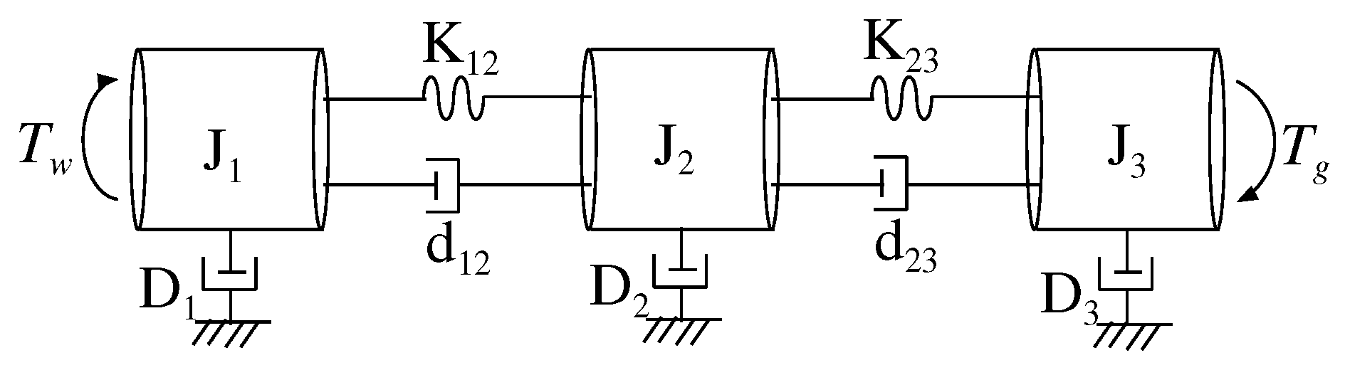
2.2. Three Inertial System Axis Model
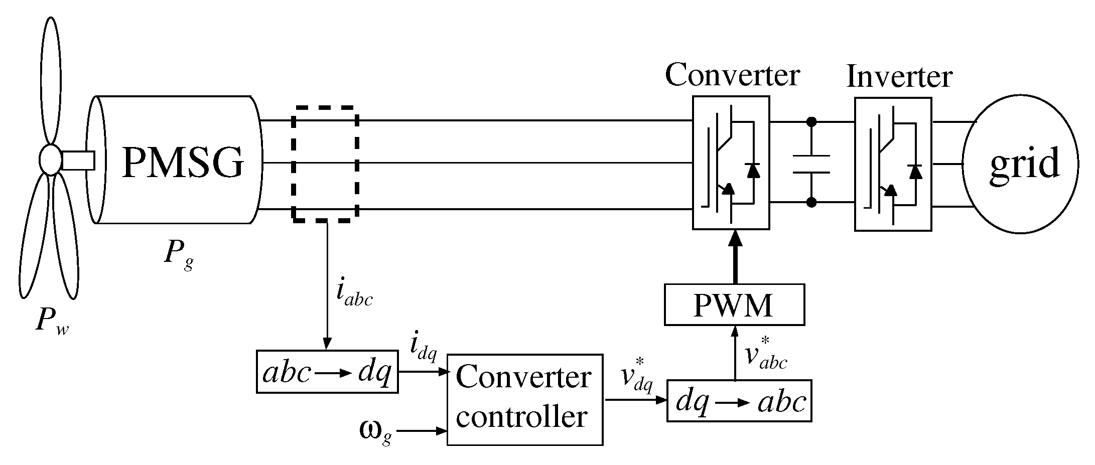
In this paper, we model the shaft system with gears by Three inertia system as shown in Figure 2 [6,15]. The equation of motion at each mass point is as follows [1,16].
J 1 d ω 1 d t = T w T 12 ( D 1 + d 12 ) ω 1 + d 12 ω 2 ,
J 2 d ω 2 d t = T 12 T 23 ( D 2 + d 12 + d 23 ) ω 2 + d 12 ω 1 + d 23 ω 3 ,
J 3 d ω 3 d t = T 23 T g + d 23 ( ω 2 ω 3 ) D 3 ω 3 ,
T 12 = K 12 ( θ 1 θ 2 ) ,
T 23 = K 23 ( θ 2 θ 3 ) ,
where each variable is as shown in Table 1 [7,17]. In addition, the damper components ( D 1 , D 2 , D 3 , d 12 , d 23 ) were neglected in order to assume a more unstable case of the shaft system this time. The frequency response of the axis system is as shown in Figure 3, and there are two resonance points. The resonance point is removed for axial torsional vibration suppression control.

2.3. PMSG

The voltage equation and the torque equation on the rotational coordinate axis (d − q axis) of PMSG are given as follows.
v d = R a i d + L d d i d d t ω 1 L q i q ,
v q = ω e L e i d + R a i q + L q d i q d t + ω e K ,
T g = p { K i q + ( L d L q ) i q i d } ,
v d and v q is d q axis voltage, i d and i q is dq axis current, L q is d q axis armature inductance, K is electromotive force coefficient, p is pole pairs and each variable is as shown in Table 1 [7,17].

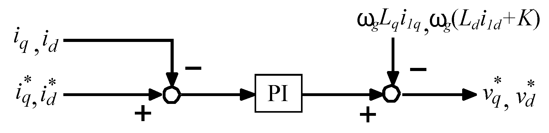
2.4. Converter of Generator Side

Currently, the AC-DC-AC link method is commonly used for power conversion method in wind power generation equipment. Figure 4 shows a conventional generator-side converter control configuration [7]. Here, the electric torque of the wind power generator is controlled by the current control on the rotational coordinate axis (dq axis). In this paper, salient pole type PMSG is used, and the d axis current command value i d is obtained from the following equation to achieve high efficiency operation [18].
i d r e f = K 2 ( L d L q ) K 2 4 ( L q L d ) + ( i q ) 2 .

3. Shaft Torsional Control System Using H Observer

3.1. H Observer

In this research, the gain design of the observer and the torsional vibration controller are designed using H control. In an actual rotating machine, it is difficult to measure the torque, and a method of estimation is needed. In this chapter, we adopt H observer which can estimate robustly against disturbance, etc. The H system model is shown in Figure 5. w is the disturbance due to the parameter error, and n is the observation noise. The H controller reduces the transfer function H norm from the disturbance to the controlled variable output. The H observer is a state observer that estimates torque that can not be measured directly. It has robust characteristics against disturbances and parameter errors. From Equations (5)–(9) and Figure 5, the state equation of the plant system is given as follows [7,19].
x ˙ ( t ) = A · x ( t ) + B · u ( t ) ,
y ( t ) = C · x ( t ) ,
A = 0 0 0 1 J 1 0 0 0 0 1 J 2 1 J 2 0 0 0 0 1 J 3 K 12 K 12 0 0 0 0 K 23 K 23 0 0 ,
B = 1 J 1 0 0 0 0 1 J 3 0 0 0 0 ,
C = 0 0 1 0 0 .
where, x ( t ) = [ ω 1 ω 2 ω 3 T 12 T 23 ] is T state variable, u ( t ) = [ T w T g ] is Input to the axis torsional system, y ( t ) = ω 3 is the observed output. Therefore, H observer design problem represents following equation.
min γ W , T w y ^ W 2 T n y ^ γ
Here, w is disturbance due to the parameter error, Estimated noise is n ˜ . T w y ^ is the transfer function from the parameter error to the observer estimate, T n y ^ is the transfer function from the observed noise to the observer estimate. The weight function W1 was set as a low-pass filter characteristic in order to take parameter errors, which is a disturbance in the low frequency region, into consideration (Figure 6a). The weighting function W2 was designed as a high-pass filter characteristic (Figure 6b) in order to take into account observation noise of high frequency. The H observer was designed using these weight functions, and the H controller, which is the observer gain, was designed by the LMI approach [20]. The frequency characteristics of the H observer are shown in Figure 7. Figure 7a is a singular value plot of the transfer function from the plant output value to the observer estimated value. It can be confirmed that the gain in the high frequency region can be reduced, and the H observer reduces the response to noise. Figure 7b is a singular value plot of the sensitivity function of the observer system. It can be confirmed that the sensitivity to errors in the low frequency region can be reduced. Next, the estimation accuracy of the designed observer is verified. Figure 8, Figure 9, Figure 10, Figure 11, Figure 12 and Figure 13 show simulation results in the axis system including high frequency noise and parameter error. Here, the parameter error gives an error of 20 % for the inertia coefficient J 1 , J 2 , J 3 and the stiffness coefficient K 12 , K 23 . The high frequency noise was a white noise with a maximum amplitude of 100. From these figures, it can be seen that the estimation accuracy is good even when the designed H observer includes a disturbance.

3.2. Torsional Vibration Suppression Control

Figure 3 shows the frequency response of the axial system [21]. It can be seen that there are two resonance frequencies in the shaft system. Torsional vibration is suppressed by removing this resonance point. We introduce the H controller into the armature current control system and control the generator side torque to satisfy the torsional vibration suppression. A shaft torsion torque control system including a weighting function is shown in Figure 5 [7]. Δ T d as input, and PMSG for suppressing shaft torsional vibration. The q-axis current command value i q is generated by the H controller. Here, Δ T d = T r e f T d , and T d is the torsion torque estimated by the H observer. The weighting functions W 3 and W 4 of the controller for suppressing steady-state deviation and suppressing resonance for following the command value are selected as shown in Figure 14a,b, respectively. The H controller is designed by the LMI approach of the MATLAB toolbox, and as shown in Figure 3, it can be seen that the elimination of the resonance point is achieved by applying the H controller.

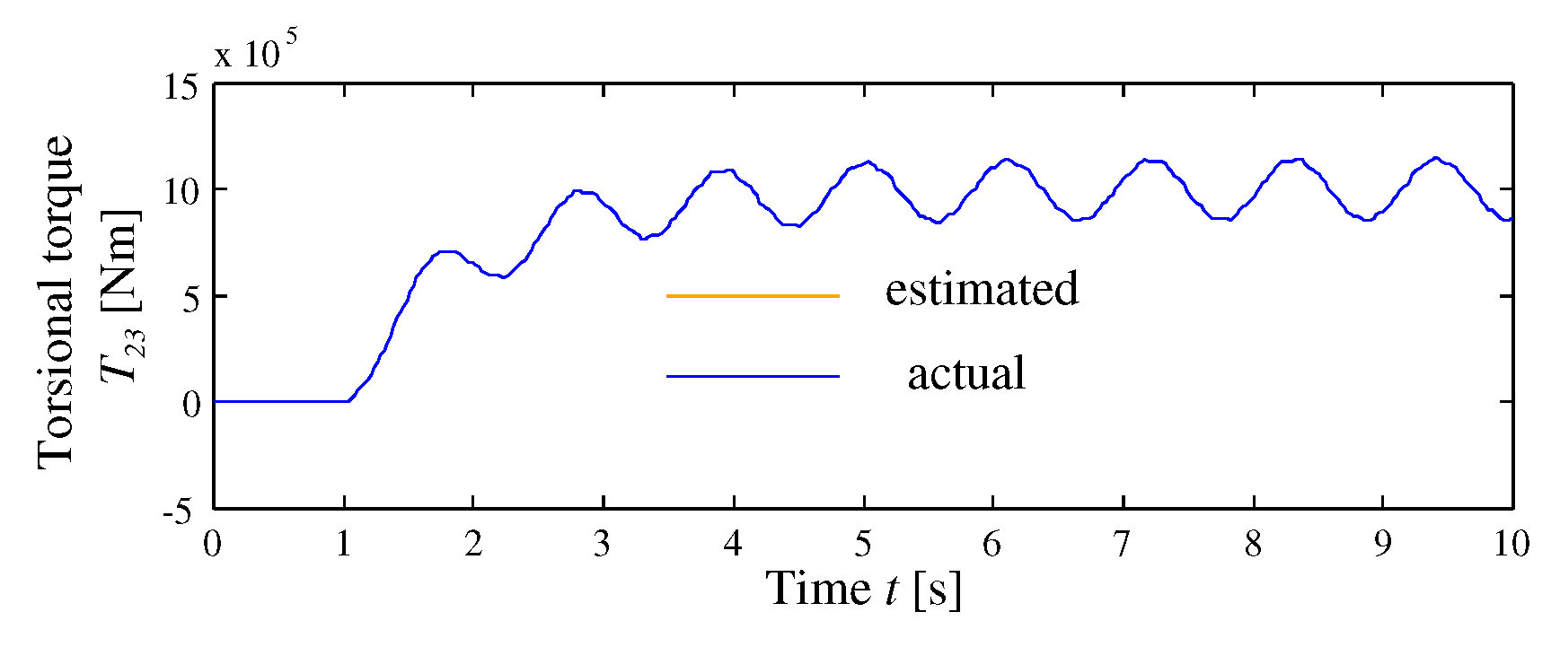
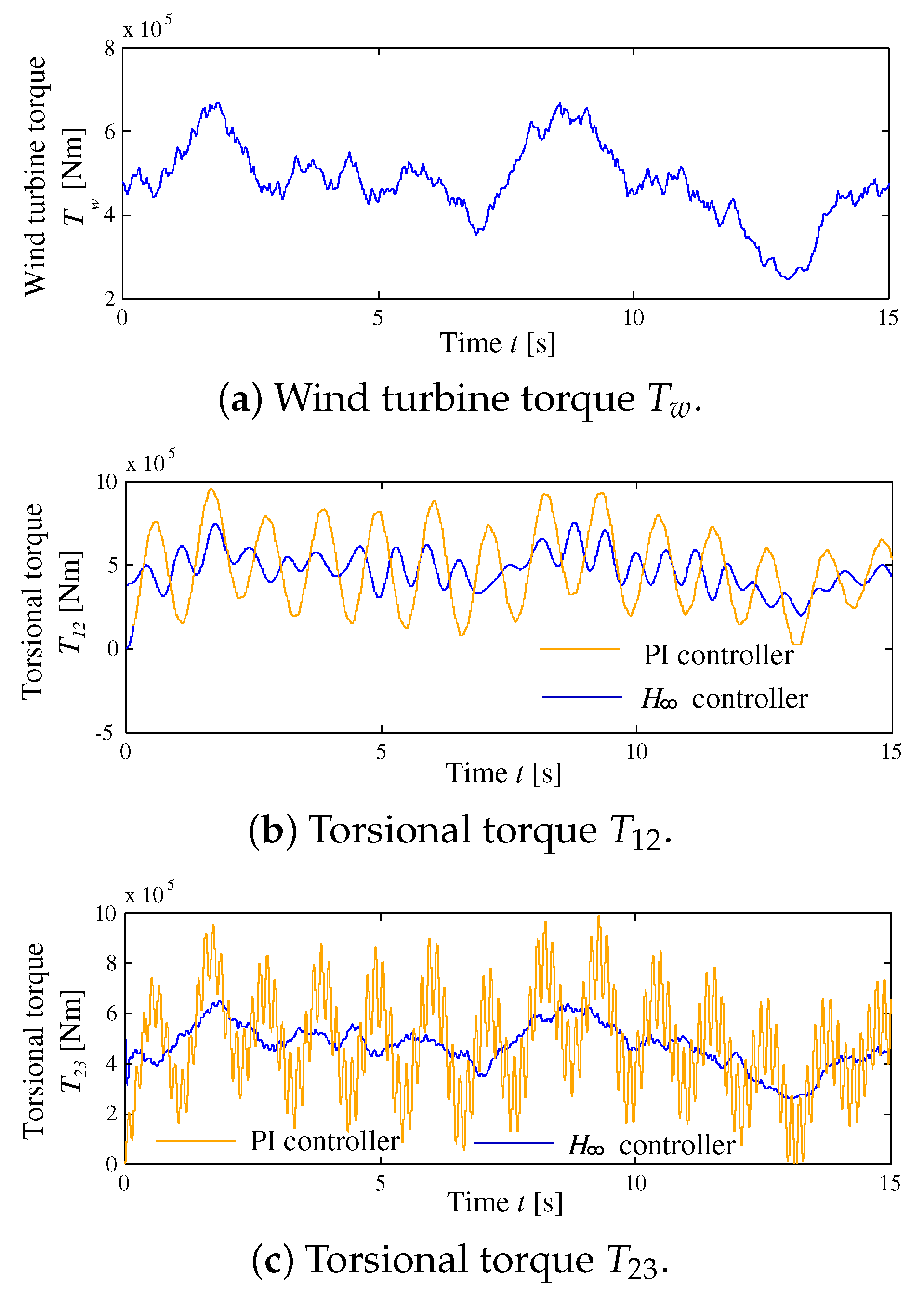
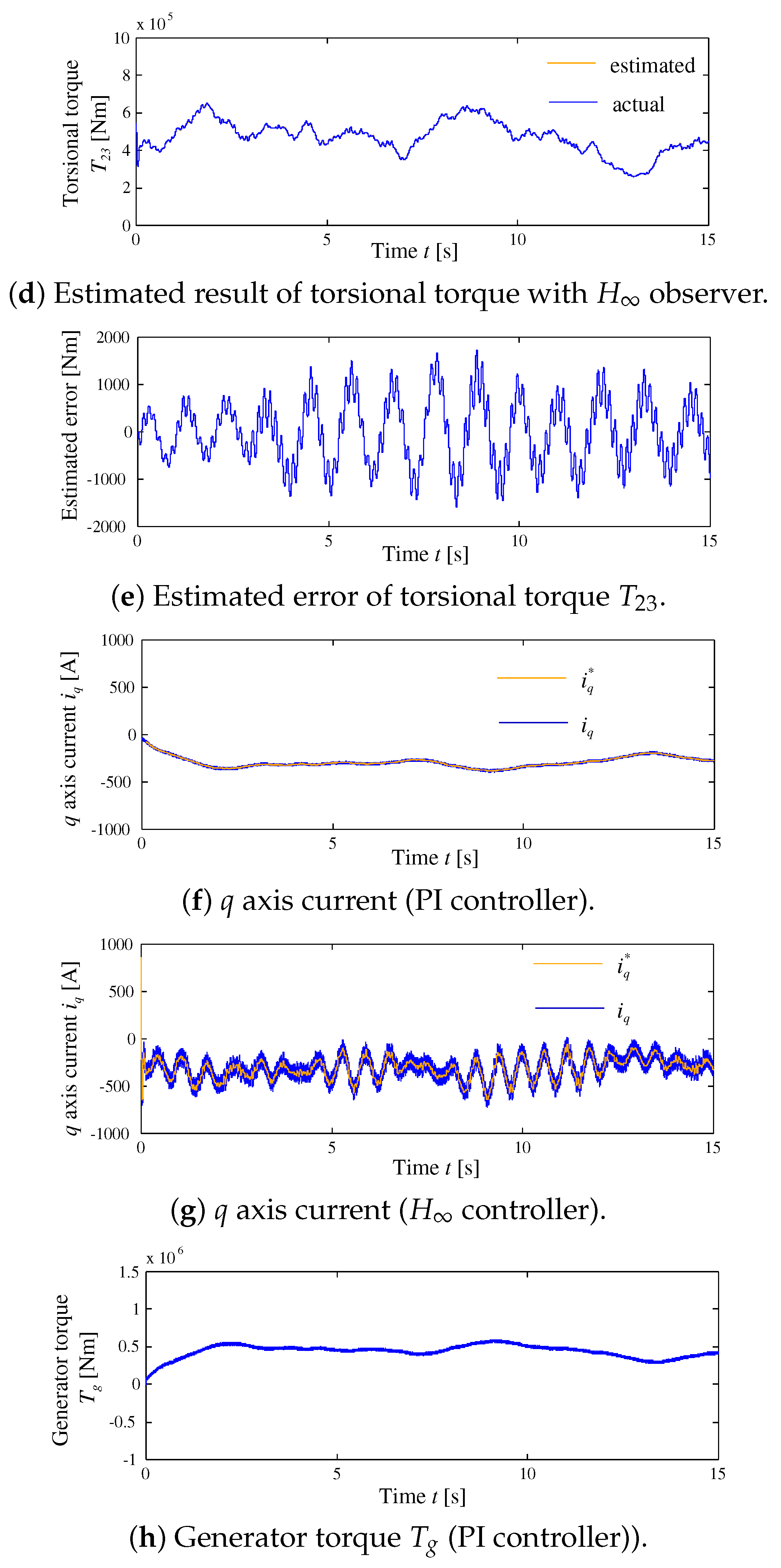
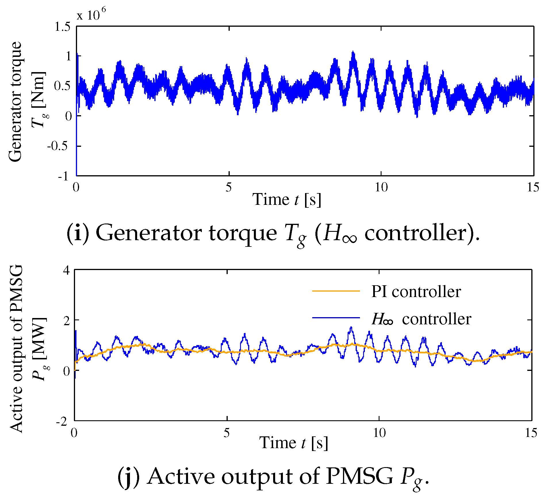
4. Simulation Results

Table 2 shows each parameter used in the simulation. Figure 15 shows the assumed wind speed. In this paper, control by PI controller is also performed for comparison. The simulation results when the observer’s state space model contains parameter errors are shown in Figure 16. The parameter error here is −20% for the inertia coefficients J 1 , J 2 , J 3 and the stiffness coefficients K 12 , K 23 . The axial torsion torque T 12 between the blade and the gear of the wind power generator and the axial torsion torque T 23 between the gear and the generator are used. The torsion torques for each shaft are shown in Figure 16b,c. The vibration is very large when the axis torsional vibration suppression control is not performed. The estimation results by H observer are shown in Figure 16d. From Figure 16c, the shaft torsional torque is estimated by the H observer even in anomalous wind conditions. Figure 16d,e show that the estimated error is small. As verified in Section 3, the estimation result by the designed H observer is good and robust even in the case of including parameter error. The control results of PI controller and H controller are compared. From this, it can be seen that the torsional vibration can be suppressed when the H controller is used for both sides. Further, these are achieved by controlling the electrical torque of the PMSG from Figure 16h,i. That is, in the simulation result by the H control, the axial torsional vibration suppression is achieved by frequently controlling the electric torque. For this reason, the generator output in Figure 16j greatly varies compared with the PI control.

5. Conclusions

For in the PMSG wind turbine generator, we estimated the torsional torque generated by the three inertial system of the wind turbine, the gear box, and the generator with the H observer and used the H controller as the armature current control system of the variable speed wind power generator to suppress shaft torsional vibration. While the generator output varied by controlling the electrical torque, the axial torsional vibration in the gear could be suppressed as compared with the case using the PI control. The proposed control method is able to suppress axial torsional vibration. This indicates that the stress suffered by the axial system was relieved. The present result suggest that greater suppression occurred even compared with two-axis H control and three-axis bandpass filter control methods for axial torsional vibration [22,23]. However, the simulation results show that the output power of the wind turbine is variable. The future challenge is to smooth output power fluctuation while suppressing the axial torsional vibration.

Author Contributions

Conceptualization, T.S.; formal analysis, K.T., and A.M.H.; methodology, K.T., N.J., S.R., and A.M.H.; resources, T.S.; supervision, T.S.; writing, original draft, K.T.; writing, review and editing, N.J., S.R., H.T., and A.M.H. All authors have read and agreed to the published version of the manuscript.

Funding

This research received no external funding.

Conflicts of Interest

The authors declare no conflict of interest.

References

  1. Kanellos, F.; Hatziargyriou, N. Control of Variable Speed Wind Turbines in Islanded Mode of Operation. IEEE Trans. Energy Convers. 2008, 23, 535–543. [Google Scholar] [CrossRef]
  2. Worku, M.Y.; Abido, M.A.; Iravani, R. PMSG based wind system for real-time maximum power generation and low voltage ride through. J. Renew. Sustain. Energy 2017, 9, 013304. [Google Scholar] [CrossRef]
  3. Yang, S.Y.; Wu, Y.K.; Lin, H.J. New application of predictive direct torque control in permanent magnet synchronous generator-based wind turbine. J. Renew. Sustain. Energy 2015, 7, 023108. [Google Scholar] [CrossRef]
  4. Tian, C.; Li, C.; Zhang, G.; Wang, M.; Wang, R. Switched model based control of dual-PWM converters in the direct-drive permanent magnet synchronous wind turbine system. J. Renew. Sustain. Energy 2018, 10, 053312. [Google Scholar] [CrossRef]
  5. Palmer, M.D.; Uehara, T.; Shigenobu, R.; Matayoshi, H.; Senjyu, T.; Datta, M. Suppression of power system voltage and frequency fluctuations by decentralized controllable loads. J. Renew. Sustain. Energy 2016, 8, 045905. [Google Scholar] [CrossRef]
  6. Sourkounis, C. Active dynamic damping of torsional vibrations by H Control. In Proceedings of the 2010 12th International Conference on Optimization of Electrical and Electronic Equipment, Basov, Romania, 20–22 May 2010; pp. 716–723. [Google Scholar]
  7. Morinaga, S.; Senjyu, T.; Funabashi, T. Torsional vibration suppression of the PMSG-based wind turbine generator using H observer. In Proceedings of the 2013 1st International Future Energy Electronics Conference (IFEEC), Tainan, Taiwan, 3–6 November 2013; pp. 880–884. [Google Scholar]
  8. Chen, J.; Chen, J.; Gong, C. On Optimizing the Aerodynamic Load Acting on the Turbine Shaft of PMSG-Based Direct-Drive Wind Energy Conversion System. IEEE Trans. Ind. Electron. 2014, 61, 4022–4031. [Google Scholar] [CrossRef]
  9. Senjyu, T.; Nakasone, N.; Yona, A.; Yousuf, S.A.; Funabashi, T.; Sekine, H. Operation strategies for stability of gearless wind power generation systems. In Proceedings of the 2008 IEEE Power and Energy Society General Meeting—Conversion and Delivery of Electrical Energy in the 21st Century, Pittsburgh, PA, USA, 20–24 July 2008; pp. 1–7. [Google Scholar]
  10. Mughal, M.H.; Guojie, L. Review of Pitch Control for Variable Speed Wind Turbine. In Proceedings of the 2015 IEEE 12th Intl Conf on Ubiquitous Intelligence and Computing and 2015 IEEE 12th Intl Conf on Autonomic and Trusted Computing and 2015 IEEE 15th Intl Conf on Scalable Computing and Communications and Its Associated Workshops (UIC-ATC-ScalCom), Beijing, China, 10–14 August 2015; pp. 738–744. [Google Scholar]
  11. Yao, X.; Guo, C.; Li, Y. LPV H-infinity controller design for variable-pitch variable-speed wind turbine. In Proceedings of the 2009 IEEE 6th International Power Electronics and Motion Control Conference, Wuhan, China, 17–20 May 2009; pp. 2222–2227. [Google Scholar]
  12. Uehara, A.; Pratap, A.; Goya, T.; Senjyu, T.; Yona, A.; Urasaki, N.; Funabashi, T. A Coordinated Control Method to Smooth Wind Power Fluctuations of a PMSG-Based WECS. IEEE Trans. Energy Convers. 2011, 26, 550–558. [Google Scholar] [CrossRef]
  13. Yin, M.; Li, G.; Zhou, M.; Zhao, C. Modeling of the Wind Turbine with a Permanent Magnet Synchronous Generator for Integration. In Proceedings of the 2007 IEEE Power Engineering Society General Meeting, Tampa, FL, USA, 24–28 June 2007; pp. 1–6. [Google Scholar]
  14. Sun, T.; Chen, Z.; Blaabjerg, F. Voltage recovery of grid-connected wind turbines after a short-circuit fault. In Proceedings of the IECON’03, 29th Annual Conference of the IEEE Industrial Electronics Society (IEEE Cat. No.03CH37468), Roanoke, VA, USA, 2–6 November 2003; Volume 3, pp. 2723–2728. [Google Scholar]
  15. Thakur, R.; Jha, N. Impact of transients due to drive train in variable speed wind energy conversion system. In Proceedings of the 2012 IEEE Third International Conference on Sustainable Energy Technologies, Kathmandu, Nepal, 24–27 September 2012; pp. 402–408. [Google Scholar]
  16. Li, H.; Zhao, B.; Yang, C.; Chen, H.; Chen, Z. Analysis and estimation of transient stability for a grid-connected wind turbine with induction generator. Renew. Energy 2011, 36, 1469–1476. [Google Scholar] [CrossRef]
  17. Geng, H.; Xu, D.; Wu, B.; Yang, G. Active Damping for PMSG-Based WECS With DC-Link Current Estimation. IEEE Trans. Ind. Electron. 2011, 58, 1110–1119. [Google Scholar] [CrossRef]
  18. Matsuse, K. Motor Control Engineering -Basic of Variable-Speed Drive-; Corona Publishing Co., Ltd.: Gloucester, UK, 2007. [Google Scholar]
  19. Howlader, A.M.; Urasaki, N.; Yona, A.; Senjyu, T.; Saber, A.Y. Design and Implement a Digital H Robust Controller for a MW-Class PMSG-Based Grid-Interactive Wind Energy Conversion System. Energies 2013, 6, 2084–2109. [Google Scholar] [CrossRef] [Green Version]
  20. Sakamoto, R.; Senjyu, T.; Kaneko, T.; Urasaki, N.; Takagi, T.; Sugimoto, S.; Sekine, H. Output Power Leveling of Wind Turbine Generator by Pitch Angle Control Using H/sub/spl infin//Control. In Proceedings of the 2006 IEEE PES Power Systems Conference and Exposition, Atlanta, GA, USA, 29 October–1 November 2006; pp. 2044–2049. [Google Scholar]
  21. Omine, E.; Goya, T.; Akie, U.; Senjyu, T.; Yona, A.; Urasaki, N.; Funabashi, T. Torsional torque suppression of decentralized generators using H observer. Renew. Energy 2010, 35, 1908–1913. [Google Scholar] [CrossRef]
  22. Licari, J.; Ugalde-Loo, C.E.; Ekanayake, J.B.; Jenkins, N. Damping of Torsional Vibrations in a Variable-Speed Wind Turbine. IEEE Trans. Energy Convers. 2013, 28, 172–180. [Google Scholar] [CrossRef]
  23. Mseddi, A.; Ballois, S.L.; Aloui, H.; Vido, L. Robust control of a wind conversion system based on a hybrid excitation synchronous generator: A comparison between H and CRONE controllers. Math. Comput. Simul. 2019, 158, 453–476. [Google Scholar] [CrossRef]
Figure 1. Configuration of power conversion control system of permanent magnet synchronous generator (PMSG) wind turbine.
Energies 13 03474 g001
Figure 2. Three mass model.
Energies 13 03474 g002
Figure 3. Frequency response of the shaft system.
Energies 13 03474 g003
Figure 4. Generator side converter control system.
Energies 13 03474 g004
Figure 5. H System model.
Energies 13 03474 g005
Figure 6. Weighting function of observer.
Energies 13 03474 g006
Figure 7. Singular value of H observer.
Energies 13 03474 g007
Figure 8. Torsional torque at without parameter error.
Energies 13 03474 g008
Figure 9. Estimated error at without parameter error.
Energies 13 03474 g009
Figure 10. Torsional torque at parameter error 20 % .
Energies 13 03474 g010
Figure 11. Estimated error of H observer at parameter error 20 % .
Energies 13 03474 g011
Figure 12. Torsional torque at with white noise.
Energies 13 03474 g012
Figure 13. Estimated error of H observer at with white noise.
Energies 13 03474 g013
Figure 14. Weight function of controller.
Energies 13 03474 g014
Figure 15. Wind speed.
Energies 13 03474 g015
Figure 16. Simulation results in Proportional-Integral (PI) control and H control.
Energies 13 03474 g016aEnergies 13 03474 g016bEnergies 13 03474 g016c
Table 1. PMSG parameters.
rated output P g 2 MW
resistance R50 μ Ω
d axis inductance L d 5.0 mH
q axis inductance L q 3.75 mH
number of pole pairs p11
field flux K136.25 V · s/rad
Generator inertia J 3 0.168 × 10 6 kg · m 2
Table 2. Wind turbine parameters.
blade radius R39 m
air density ρ 1.205 kg/m 3
rated wind speed V ω 12 m/s
Gear ratio N g e a r 1
Wind turbine inertia J 1 2.173 × 10 6 kg · m 2
Gear inertia J 2 0.080 × 10 6 kg · m 2
Shaft stiffness K 12 7.554 × 10 6 N · m/rad
Shaft stiffness K 23 90.65 × 10 6 N · m/rad

