Article

Gassing Tendency of Fresh and Aged Mineral Oil and Ester Fluids under Electrical and Thermal Fault Conditions

Research Chair on the Aging of Power Network Infrastructure (ViAHT), Université du Québec à Chicoutimi, Chicoutimi, QC G7H 2B1, Canada
*
Author to whom correspondence should be addressed.
Energies 2020, 13(13), 3472; https://doi.org/10.3390/en13133472
Submission received: 30 April 2020 / Revised: 21 June 2020 / Accepted: 3 July 2020 / Published: 5 July 2020
(This article belongs to the Section A: Sustainable Energy)

Abstract

:
Operational factors are known to affect the health of an in-service power transformer and to reduce the capabilities and readiness for energy transmission and distribution. Hence, it is important to understand the degradation rate and corresponding behavioral aspects of different insulating fluids under various fault conditions. In this article, the behavior of mineral oil and two environmentally friendly fluids (a synthetic and a natural ester) are reported under arcing, partial discharges, and thermal fault conditions. Arcing, partial discharges and thermal faults are simulated by 100 repeated breakdowns, top oil electrical discharge of 9 kV for five hours, and local hotspots respectively by using different laboratory-based setups. Some physicochemical properties along with the gassing tendency of fresh and aged insulating liquids are investigated after the different fault conditions. UV spectroscopy and turbidity measurements are used to report the degradation behavior and dissolved gas analysis is used to understand the gassing tendency. The changes in the degradation rate of oil under the influence of various faults and the corresponding dissolved gasses generated are analyzed. The fault gas generations are diagnosed by Duval’s triangle and pentagon methods for mineral and non-mineral oils. It is inferred that; the gassing tendency of the dielectric fluids evolve with respect to the degradation rate and is dependent on the intensity and type of fault.

1. Introduction

Alternative dielectric fluids for use in oil-filled apparatuses is a topic of concern for industry and utilities for decades. Ester dielectric fluids (both natural and synthetic esters) are being investigated for use in oil-filled transformers. The dielectric properties and rate of deterioration of ester fluids is comparable to those of mineral insulation oils used in power transformers [1]. The compatibility of these alternative fluids with solid insulants was investigated and reported possible longevity of cellulose insulants when used with ester dielectric fluids [2]. The pre-breakdown phenomena, workability, influence of temperature, compatibility with other transformer materials, and service experience were reported by various researchers [1,3,4,5]. Several researchers also attempted to understand the regeneration aspects and end of life criteria of these insulating fluids [6]. From the extensive laboratory studies, IEEE Standards and CIGRE reports came to the acceptance of using these fluids in oil-filled transformers [7,8,9]. However, condition monitoring and diagnostic tools for ester-filled transformers is still a topic of high interest for the industry. Meanwhile, the possibility of ester fluids to be miscible with mineral insulating oils was a topic of research to understand the feasibility of retro filling existing units. Fofana et al. [10,11] reported the properties of various mixtures of mineral oil and ester fluids extensively. Later, U. Mohan Rao et al. [12,13] reported the long-term degradation behavior, degradation solid insulation in mixture insulating fluids. Nevertheless, ester fluids are being used in oil-filled transformers and various utilities across the globe started filling/retrofilling some new and existing transformers with ester liquids. There is a large scope for research including, but not limited to, the understanding of the behavior of these insulating fluids under different operating conditions, regeneration aspects, and condition monitoring aspects.
Despite due care is taken by manufacturers and utility, yet there is a high probability for electrical discharges and local hotspots. The presence of electrical discharges and local hotspots for longer duration leads to high electrical discharge and thermal failures. The electrical faults are low and high-energy discharge electrical faults, which are treated as corona discharges, partial discharges, and breakdown. Thermal faults are the accumulation of heat over a local area and are treated as hotspots. Both electrical and thermal faults are originated because of various reasons including, dielectric defects, air bubbles, impurities, sharp edges, and any manufacturing defects. The presence of these faults hampers the integrity of the insulation system in various aspects and is detrimental to a transformer. Therefore, early detection of these faults is of high importance to condition monitoring engineers and maintenance planners. It is well established that, these faults are involved in the generation of several gasses that are dissolved in the oil. Therefore, the dissolved gas analysis is seen as one of the important conditions monitoring and diagnosis tools.
Numerous researchers have reported the gassing tendency of various dielectric liquids under different fault conditions. The tendency to gassing generation under partial discharges or low energy discharge electric faults in mineral oils and ester fluids were investigated and reported in [14,15,16]. It is reported that higher quantities of C2H2 and H2 are generated in natural esters and C2H2 remains the key gas to indicate a defect or fault witnessed by electrical discharges. Also, the influence of high energy discharges on the gassing tendency of the dielectric fluids have been reported in [14,17,18]. Similar to the low energy discharge faults, H2 and C2H2 are found to be witnessed due to arcing fault conditions. However, a large amount of C2H2 is generated as compared to the low energy discharge cases. The gassing tendency of ester fluids under thermal faulty condition was also investigated and are reported in [14,15,18,19,20]. It is found that natural ester generates more gases at a higher temperature (>300 °C) and traces of C2H6 are found increasing with increasing temperature. The key gasses in ester fluids under thermal faults are found to be CH4, C2H4, CO, and C2H6. However, there are different methods for simulating the hotspot at different temperatures; the gassing tendency of the dielectric fluid varies accordingly. The details are critically analyzed and summarized in [21]. It is to be mentioned that, the fault diagnosis approaches discussed above are limited to a single fault i.e., electrical or thermal fault alone. However, in the real transformer, there are possibilities for the electrical and thermal faults to occur simultaneously. Thus, in [22] a combination of electrical and thermal faults was studied. The authors reported the gassing tendency at different combinations of electrical and thermal faults while varying fault temperatures and fault voltages. The trending of fault gasses has been explicitly reported under different laboratory conditions.
Electrical discharges, electrical arcing, and thermal faults in a transformer influence the degradation of the oil accompanied by faults gas generations. These faults also, expedite the degradation reactions in a transformer, which together with acids and heat accelerate deterioration of the insulation system. It is to be understood that the intensity of this degradation process and fault gasses are also attributable to the condition of the oil. In other words, the occurrence of the same fault with the dielectric fluid at two different conditions (age) will have different levels of consequences. Recently, authors from our research group have reported the influence of aging on the gassing tendency and oil’s degradation under low energy electrical discharge faults for mineral oil and synthetic esters [23].
It was reported that the condition (age) of the oil has a significant influence on the concentration of the dissolved gases which affects the fault diagnostic conditions. Also, the influence of thermal aging on the gassing tendency of mineral oil and natural esters under the influence of thermal faults has been reported in [19]. A significant change in the dissolved gas concentration has been noticed with an increase in the thermal aging duration of the dielectric fluids. Hence, there is a need to study the gassing behavior of ester-based dielectric fluids (both natural and ester) under the influence of electrical and thermal fault conditions at different aging conditions and the influence of the faults on oil degradation. Therefore, the present research is aimed to understand the influence of aging or state of the dielectric liquid on gassing tendency under different operating faulty conditions. The authors have also focused the influence of different faults on the degradation of the dielectric fluids. In the present work a mineral oil, a synthetic ester, and a natural ester have been investigated under low electrical energy discharge, high electrical energy arcing, and hotspot faulty conditions. The degradation of the insulation liquids is monitored by adopting UV spectroscopy and turbidity measurements as per ASTM D6802 and ASTM D6181 standard test methods respectively. The dissolved gas analysis measurements are performed as per ASTM D3612.

2. Experimental

2.1. Samples

For the present study, a mineral oil (MO), a natural ester (NE), and a synthetic ester (SE) have been adopted. The properties of the fresh unused oils considered for this study are tabulated in Table 1.
Unused mineral oil, synthetic ester, and natural ester have been subjected to thermal aging according to a modified ASTM D1934 standard method at 115 °C for 2000 h. The thermal aging is performed with the copper catalyst (3 g/L) and cellulose Kraft papers (1:20). After the thermal degradation procedure, highly degraded oil/paper insulation is subjected to sonication for 30 s using Qsonica Q1375 Sonicator. This sonication allowed to prepare a gentle solution of degraded oil and paper. Further, the individual solutions of MO, NE, and SE are separately added to unused MO, NE, and SE respectively. The proportions of the degraded solution added to unused oils allowed controlling the acid values of the oils. This facilitated having oil samples with a specific level of acidity that refers to a bad class of the oil aging as per [24].
It is to be mentioned that attaining a predetermined value of acidity is not feasible with the traditional thermal aging process. Therefore, the authors prepared a degraded solution which is later used to obtain a specific value of the acidity by adding it in suitable proportions. Now, these aged oils (obtained with the desired acidity values) along with fresh unused oils are used for the present study. The details of the acidity measurements of the bad class are illustrated in Table 2.

2.2. Laboratory Simulation of Electrical and Thermal Faults

2.2.1. High Energy Discharges (Arcing)

High energy discharge faults are stimulated by repeated breakdowns to produce arcing in the oil volume. The breakdown of the insulation fluid is performed in the laboratory as per ASTM D 877. To simulate the sustainability of the arcing fault, 100 breakdowns have been performed with 2 min of break between each breakdown. To understand the impact of high-energy discharge electrical faults, dissolved gas analysis is performed after 100 continuous breakdowns. To understand the influence on oil degradation, UV spectroscopy and turbidity measurements are reported before and after 100 breakdowns. The details of the breakdown test set up are presented in Figure 1a and the series of breakdowns for MO, NE, and SE for fresh and aged oils are shown in Figure 1b. In addition, the total average energy used for 100 breakdowns in various liquids is tabulated in Table 3.
It is observed that, breakdown of the dielectric liquids is increasing with aging and with the number of breakdowns. To understand this, it is to be recalled that water saturation limit of dielectric liquids increases with increase in aging [25]. Also, breakdown voltage is dependent on relative moisture content and hence breakdown voltage of the aged oil will be higher than that of the fresh oil at a given absolute moisture content. Under AC stress, a field-induced drift of particles, located in high field regions, can be entailed by a stress relieve leading to an improvement of the dielectric strength, compared to technically clean oil [26]. In the same way, breakdowns cause definite degradation; this will lead to an increase in the water saturation on average with breakdown times.

2.2.2. Low Energy Discharges (Partial Discharges)

Low energy discharges electrical faults are often called partial discharges, which could be internal discharge, surface discharge, and corona discharges. In the present work, a laboratory set up has been used to produce a surface discharge of 9 kV. A 9 kV electrical discharging activity is simulated for 5 h on the surface of the dielectric fluid. The free electrons are generated by a cylindrical copper electrode sealed in a 500 mL Erlenmeyer glass. The electrode is placed in the center of the discharge cell and suspended above the oil’s surface. The distance between the central electrode and the surface of oil is approximately one inch. The details of the experimental set-up was reported by the authors from our research group in [23] and is shown in Figure 2a. The discharge is initiated after vacuuming the test cell and the changes in the pressure with discharging time are recorded to understand the gassing behavior of the insulating fluid. This method is useful in understanding the stability of the insulating fluids to gassing behavior. The pressure changes in the test cell with fresh and aged MO, NE, and SE as a function of discharging time are shown in Figure 2.

2.2.3. Thermal Faults (Hotspot)

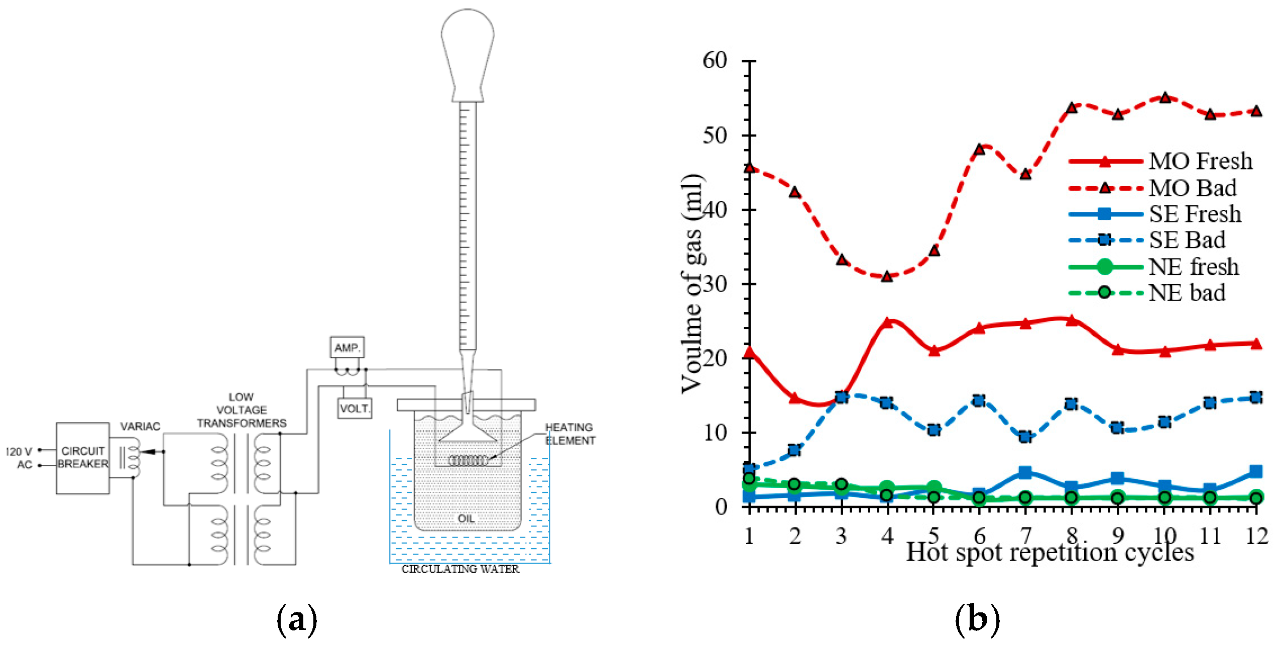
Thermal faults or hotspots simulation in MO, NE, and SE have been simulated by developing a laboratory-based test set up. The setup used for simulating thermal faults is presented in Figure 3a. The set up consists of a borosilicate-glass vessel and a Teflon cover with bushings to hold the heating element. Constantan was chosen for the heating element for its flat resistivity on a large scale of temperature. The input supply is connected to a variac that feeds two high current transformers connected in parallel while the temperature of the wire was regulated by an ammeter and voltmeter connected between the heating element and the secondary. By measuring the voltage and current, the average temperature of the hotspot may be approximated. This is also validated by using a high-temperature resistant thermocouple. An aluminum funnel-shaped structure is placed just over the heating element. This is because the generated gas bubble enters the pipette through this funnel structure according to the Archimedes’ principle where they can be measured. In each experiment, a quantity of 800 mL of dielectric fluid was introduced to fulfil the vessel and the pipette up to the reference value. The fluid samples under hot-spot tests are allowed to heat for periods of 30 min and the volume of gas generated is recorded. The temperature reached values close to 250 °C, which for the mineral is risky because of its flashpoint. For safety reasons, the current is zeroed until the temperature of the insulating fluid equals the room temperature (~24 °C). This test cycle of 30 min of heating and cooling down to room temperature have been repeated for 12 times. For every 30 min of the heating cycle, the volume of gas is recorded. The volumes of the gases generated as a function of the heating cycles are presented in Figure 3b.

3. Results and Discussions

The results of the degradation rate of the oil, before and after simulating electrical and thermal faults are discussed in this section. As mentioned earlier, the degradation of the insulating liquids has been understood by ultraviolet visible spectral curves, dissolved decay contents, and turbidity. The details of the fault gasses evolved because of the characteristic faults have been analyzed by dissolved gas analysis and application of Duval’s diagnostic methods reported in the literature. To have a clear observation and to avoid direct comparison of various insulating oils, the authors have presented the results oil by oil with all types of faults. Also, it is difficult to obtain similar level of the fault intensity in order to compare fault by fault. Therefore, it is interesting to see the impact of the same type of faults in a dielectric fluid at different aging conditions (Fresh and Bad classes). The following notations presented in Table 4 are used for representing different cases of the insulating liquids.

3.1. Degradation of Insulating Fluids

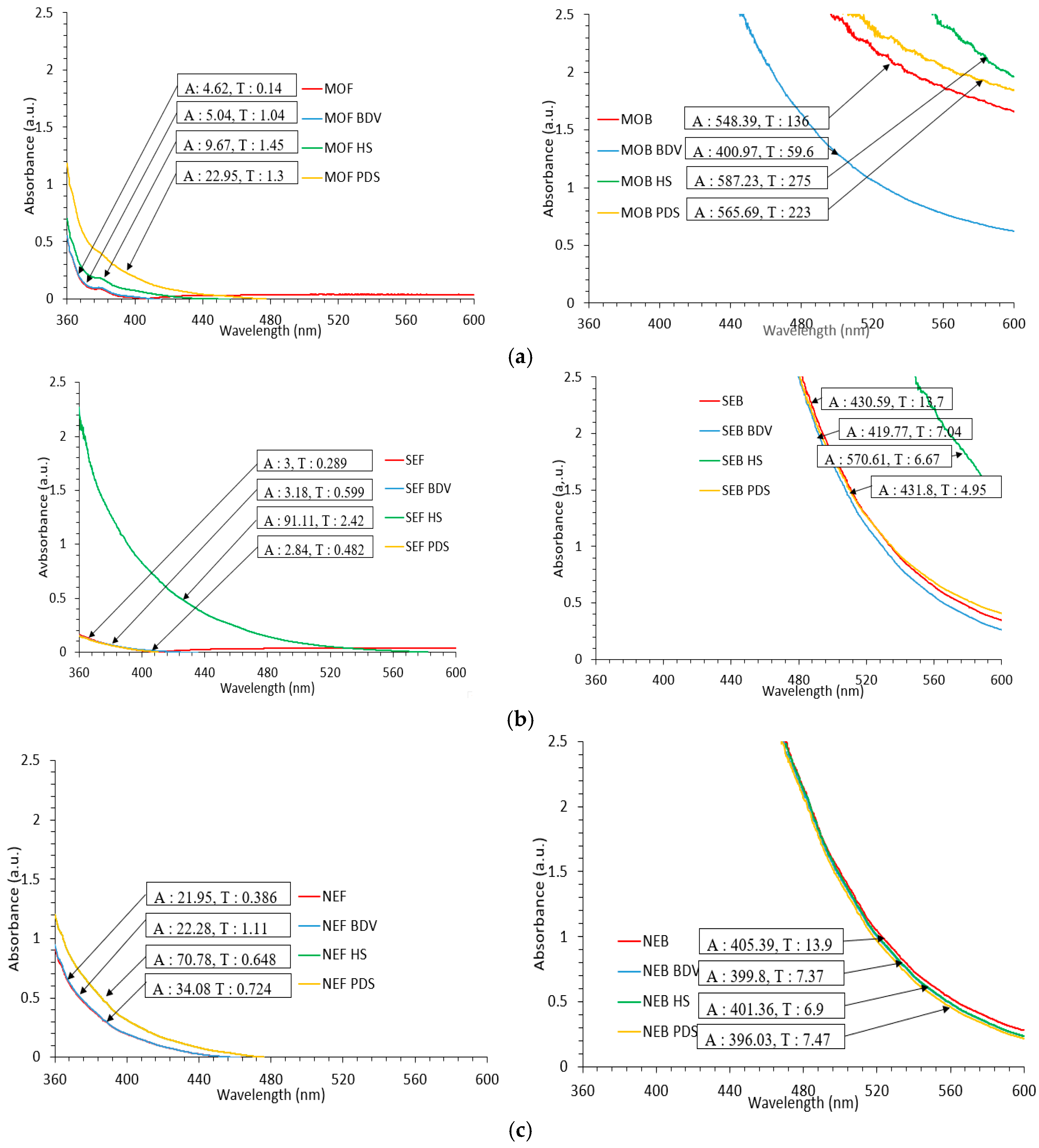
In the present section, the degradation of fresh and aged oils while subjected to electrical and thermal faults is of concern. Fresh oils are technically clean and are free from decay particles and cellulose particles, and other aging byproducts. Whereas, aged oils contain, cellulose particles, dissolved decay products, acids, and other aging byproducts. Therefore, when a fresh oil and aged oil are subjected to different fault conditions, the undergoing chemical perspectives are expected to be different. Subsequently, the influence of these faults on the dielectric fluids will be different. Hence oil absorbance, dissolved decay products, and turbidity are measured for before and after subjecting the liquids to the fault conditions. The details have been presented in Figure 4.
In fresh oils, the changes that occur because of the application of thermal and electrical faults depend majorly on the thermal stability of the chemical bonds and the ionization potential respectively. In case of aged oils, along with the said factors, the concentration of colloidal and soluble decay particles plays a significant role in further degrading a dielectric fluid. Therefore, in the present research, the concentration of the dissolved decay products and turbidity measurements have been reported. From Figure 4, it is seen that aged oils have a high turbidity, decay content concentration which is obvious. It is to be noticed that, the application of fault conditions (both electrical and thermal) had a different impact for fresh and aged oils. In Figure 4a, from fresh mineral oil, the influence of partial discharges is high as compared to arcing and hotspot. Similarly, in the case of aged oils, the hotspot influence is superior to that of the partial discharges and arcing. However, it is seen that the absorbance of aged oil is reduced with arcing. This may be due to the splitting or de-agglomeration of the cellulose particles present in the oil which reduces the absorption to light. To further understand this, the chemical function group analysis is to be understood. The absorbance and turbidity of the aged oil are increasing with partial discharges and thermal faults. From Figure 4b, it is noticed that, the influence of hotspot is higher than that of the partial discharges and arcing for fresh and aged synthetic esters. Also, the influence of partial discharges and arcing is too low in the case of fresh and aged fluid samples. One may understand that, the influence of electric faults is low when compared to thermal faults in the case of synthetic esters. However, it is to be assured that, the intensity of the fault nature is uniform in all three cases. Also, in Figure 4c, the influence of the hotspot is higher when compared to the other faults in the case of fresh natural esters. To understand the influence, faults of much higher intensities are to be evaluated. It is to be recalled that, thermal faults involve an increase in local temperature and promoting oxidation of the oil/paper insulation. These generated acids trigger a self-sustained process called hydrolysis which in turn degrades the solid insulation. But, in case of electrical faults, the influence is more associated to a generation of acids and free radicals which leads the degradation. However, both electrical and thermal faults are involved with the generation of dissolved gasses. The detailed analysis of dissolved gas analysis is presented in the next section.

3.2. Gassing Tendency of Insulating Fluids

The dissolved gas analysis for mineral oil and non-mineral oils are analyzed according to IEEE C57.104 and IEEE C57.155 respectively. As per of IEEE C57.104 and IEEE C57.155 the following are the observation on gas trending in mineral oil and non-mineral oils respectively for different fault conditions.
Arcing faults: With high energy discharges, traces of CeH2 and C2He increase in mineral oils and C2H6 is generated in ester fluids. However, H2, CH4, C2H4, C2H2 are witnessed in common with arcing faults and C2H2 need proper monitoring to diagnose arcing failures.
Partial discharge faults: With low energy discharges in the initial stages CH4 and small traces of C2H2 increases and at an advanced stage; traces of C2H2 and C2H4 raises in mineral oils. In ester fluids, H2 and C2H2 are witnesses. However, severe traces of H2 remains common in both dielectric liquids. Hence, H2 and C2H2 may be monitored for identifying low energy discharging activities.
Thermal faults: Local hotspots in mineral oil increases H2, CH4, C2H4, C2H6, and C2H2 whereas in ester oil, H2, CH4 and C2H6, and some C2H4 increases.
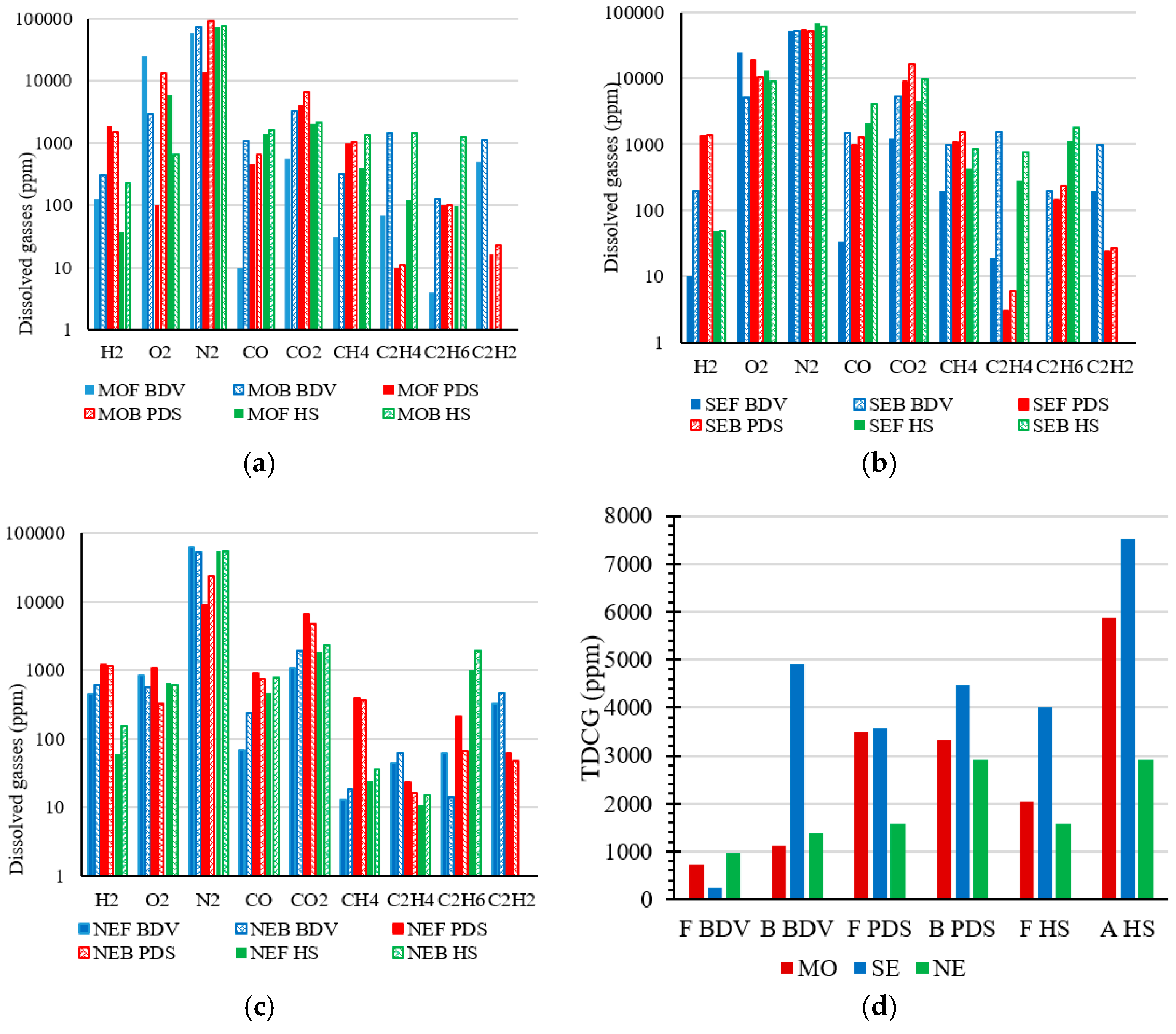
However, electrical and thermal faults are mostly associated with cellulose insulation and degradation of cellulose is accompanied by the generation of CO and CO2 gases. Hence, the above discussed faults are also mostly witnessed by CO and CO2 gases for cellulose-based insulation systems. Also, the influence of aging on the gassing behavior is not addressed in the said standards. In the present work, dissolved gas analysis has been performed on fresh and aged mineral oil and ester fluids after subjecting to partial discharges, arcing, and thermal hotspot. Hence, the gases generated under the influence of different faults for a dielectric liquid with aging are discussed in this section. The details of the dissolved gases for different oils under different faults for mineral oil, natural, and synthetic esters are shown in the Figure 5.
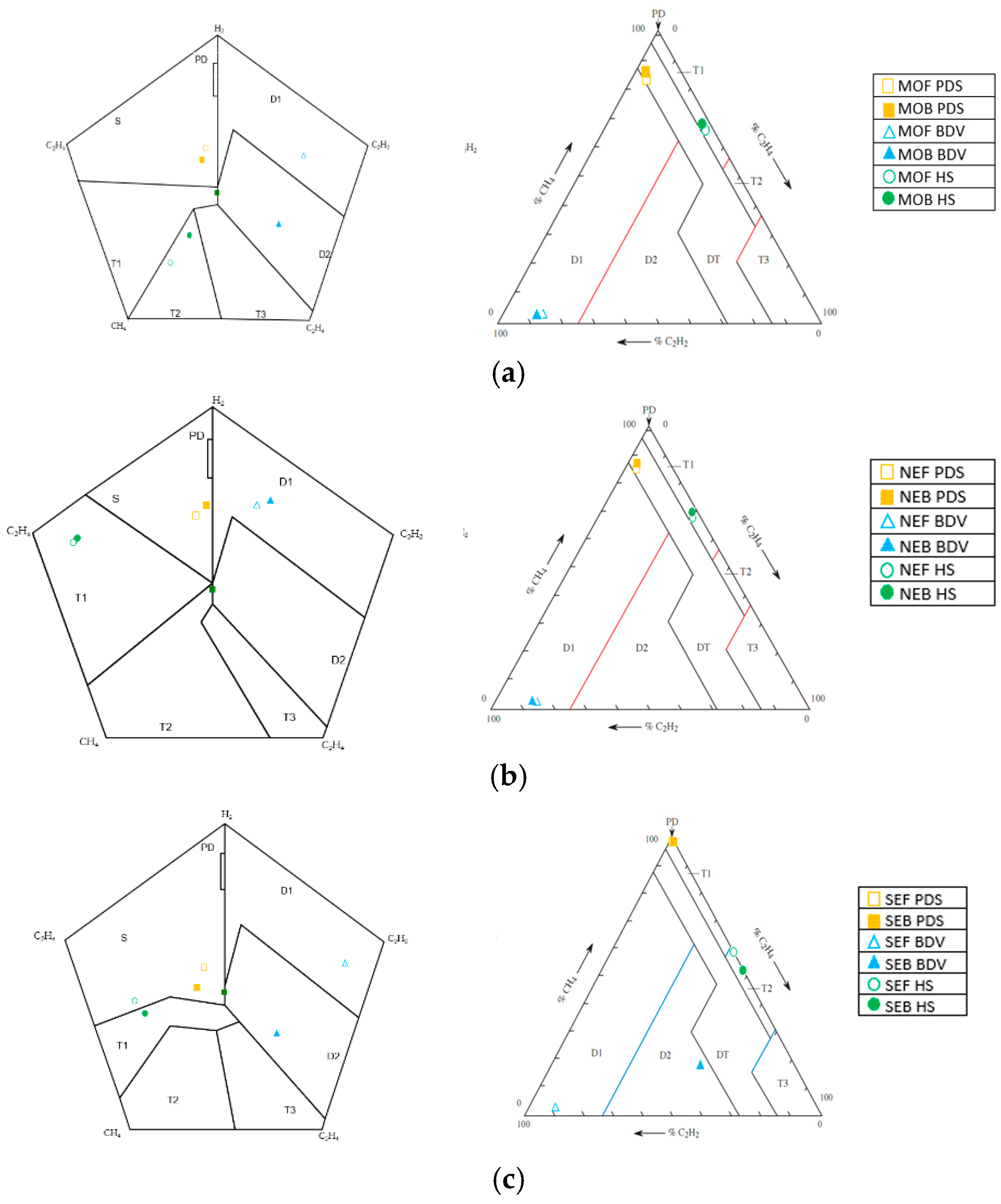
It is noticed that, the concentration of the majority of the gasses is higher in case of aged oil under the influence of thermal and electrical faults. For arcing faults, H2, CH4, and C2H2 are found to increase in all the dielectric fluids. However, O2 is reduced and significant change is not noticed in the traces of N2 for fresh and aged oils. Thus, H2, CH4, and C2H2 gas concentrations vary with the state condition of the oil under arcing faults for mineral oils and non-mineral oils. For partial discharge faults, a much less change in H2 and C2H2 is noticed for fresh and aged oils. This is because, cellulose decay particles act as a filtering and absorbing medium under low energy discharge fault conditions [27]. However, there is almost no change in CH4, C2H4, and C2H6 for fresh and aged mineral oil. For ester fluids, a noticeable change in the traces of CH4, C2H4, and C2H6 are noticed. Therefore, under partial discharging activity, CH4, C2H4, and C2H6 vary with the condition of the ester fluids and H2 will be generated in common for both the fluids according to the state of the oil. For thermal faults, there is a significant change in H2, CH4, C2H4, and C2H6 in mineral oil while in ester fluids, there is a small change in CH4, C2H4, and C2H6. This is because of the fault temperature which is not more than 400 °C and hence a significant change in C2H6 and C2H2 are not witnessed. Hence, under thermal faults with less temperatures, H2, CH4, C2H4, and C2H6 gases will be generated in common for both the fluids according to the state of the oil. From Figure 5b, it is noticed that, the generation of combustible gasses increase with increasing degradation of the oil. However, the generation of combustible gasses are higher for partial discharging and hotspot activity. This is because, the degradation of dielectric fluids is accelerated by cellulose decay particles, and other conductive particles. Therefore, excessive amounts of CO and H2 increases easily in any event of the fault, thus aiding to the increase in TDCG. The illustration of Duval’s triangle and Duval’s pentagon with the fault distribution locations are shown in Figure 6 for mineral oil, natural, and synthetic esters.
To further understand the influence of the condition of the dielectric liquid on gassing tendencies under different faults, Duval’s triangle and Duval’s pentagon methods for mineral oil and non-mineral oils have been applied for mineral oil and ester fluids respectively. Both fault diagnosing methods indicate that faults evolve with degradation duration. However, this phenomenal changing depends on the intensity of fault and the degradation rate of the insulation system. The insulation system degradation rate is highly dynamic and hence the gassing tendency of the dielectric fluid remains dynamic with operation time. Because as per Duval’s methods, any disagreement or mismatching in the fault type using triangle and pentagon methods indicate the presence of more than one fault [28]. Such a measurement requires more investigations to diagnose the fault. To illustrate changes of fault gas, both diagnosing methods and authors’ observations on fault matching have been summarized in Table 5. It is to be noticed that, there is a high disagreement between all partial discharge fault samples for all the dielectric fluids. It is to be recalled that, in the present study, a spark is discharged on the surface of the liquid applying 9 kV voltage for five hours. The stray gassing is noticed for fresh dielectric fluids in case of partial discharging activity of the present study. One may understand that even minor partial discharging activities with low energy and for short durations will lead to stray gassing and involves in local temperature raise. To further comment on this, a detailed study on the type of fault diagnosis for partial discharges with different energy levels and different types (surface discharge, internal discharge, and corona discharge) is required. For arcing faults, the fault diagnosis matched for fresh samples (mineral oil, and ester fluids). However, aged mineral oil does not match but the similarity may be accepted as they are electrical discharge faults with different intensities. This is due to the aging impact; it is to be recalled that cellulose decay particles have been manually added to get the required acidity values.
It is known that the degradation of cellulose is much higher in mineral oils as compared to ester fluids. Hence, these decay particles added to the oil, differently influence the oil with arcing when compared to the ester fluids. Hotspot simulation faults almost matched or partially matched for all samples. However, fresh natural ester confined to stray gassing while aged natural ester result in thermal fault in case of Duval’s pentagon whereas aged oils confined to thermal faults.
It is to be mentioned that care is taken during the experimentation to avoid interaction of the liquid with external air. Albeit all the three setups are hermetically sealed, a neck headspace is allowed in the test cells. This neck headspace is facilitated for the safety purposes, oil expansion, and to easily accommodate the bubble pressure created. Thus, there is a scope for the fault gasses to escape in the gas phase too. The above results are inclusion of only the fault gas that is dissolved in the liquid phase. To understand the gases in the gas phase, Ostwald solubility coefficient (L) of different gasses presented in IEEE Std C57.104 are used. The details of the Ostwald coefficients, gas phase gasses, liquid phase gasses, and total gas generation are presented in the Table 6.
It is to be mentioned that, the details of Ostwald solubility coefficients in case of ester fluids are not yet reported in IEEE Std C57.155. Therefore, for illustration purposes the coefficients reported in IEEE Std C57.104 have been used in the present study. Further, it is already arguable for the use of single Ostwald coefficient even for mineral oil as the aging of oil affects the partial pressure of the gases. Therefore, it will be quite difficult to justify the use of a single Ostwald coefficient for both mineral and ester liquids. Hence, it is to be understood that, the changes/variations in the gassing tendency in different liquids at different aging conditions may also be attributable to these factors. The details of accuracy and repeatability of individual gases measurements are provided in Table 7.

4. Conclusions

The influence of the condition of the dielectric fluid on gassing has been reported for mineral oil, natural, and synthetic esters under electrical and thermal faults. The degradation under fault conditions has been reported using dissolved decay contents, absorbance, and turbidity. The dissolved gas analysis by the application of Duval’s fault gas diagnostic methods are adopted to understand the gassing behavior of the dielectric fluids. It is inferred that, fault gases in a transformer evolve with respect to degradation of the dielectric fluid. As degradation of the fluid is highly dynamic with operating times, there is a need to understand the gassing tendency of an insulation liquid vis-à-vis aging markers. It is also found that, the concentration and type of dissolved gasses generated depend on the type of fault. In other words, the gassing tendency and fault gasses will not be the same for a similar type of fault at different fault durations and fault energy. The theoretical premise that aging by-products affects the gassing tendency and DGA is experimentally confirmed. The results reported in this study should be helpful in further improving the dissolved gas analysis of ester filed transformers. Dissolved gas analysis is a potential fault diagnosing tool having a large variance in the research results reported by various researchers across the globe. Thus, demanding need to emphasize the research on dissolved gas analysis of alternative dielectric fluids at different aging conditions, different fault intensities, and fault durations.

Author Contributions

This work was done under the supervision of I.F. holder of the Research Chair on the Aging of Power Network Infrastructure (ViAHT) and U.M.R. at the Université du Québec à Chicoutimi, (QC, Canada). L.L. and U.M.R. designed this research, carried out measurements, and collected all the data. L.L. and U.M.R. carried out result analysis, result display, and wrote the manuscript. The final draft of the manuscript was thoroughly reviewed by I.F. All authors have read and agreed to the published version of the manuscript.

Funding

The Research Chair on the Aging of Power Network Infrastructure (ViAHT) at Université du Québec à Chicoutimi, Chicoutimi supported and funded this research.

Conflicts of Interest

The authors declare no conflict of interest.

References

  1. Mohan Rao, U.; Fofana, I.; Jaya, T.; Rodriguez-Celis, E.M.; Jalbert, J.; Picher, P. Alternative dielectric fluids for transformer insulation system: Progress, challenges, and future prospects. IEEE Access 2019, 7, 184552–184571. [Google Scholar] [CrossRef]
  2. Abdelmalik, A.A. Analysis of thermally aged insulation paper in a natural ester-based dielectric fluid. IEEE Trans. Dielectr. Electr. Insul. 2015, 22, 2408–2414. [Google Scholar] [CrossRef]
  3. Rafiq, M.; Lv, Y.Z.; Zhou, Y.; Ma, K.B.; Wang, W.; Li, C.R.; Wang, Q. Use of vegetable oils as transformer oils—A review. Renew. Sustain. Energy Rev. 2015, 52, 308–324. [Google Scholar] [CrossRef]
  4. Ghani, S.A.; Muhamad, N.A.; Noorden, Z.A.; Zainuddin, H.; Bakar, N.A.; Talib, M.A. Methods for improving the workability of natural ester insulating oils in power transformer applications: A review. Electr. Power Syst. Res. 2018, 163, 655–667. [Google Scholar] [CrossRef]
  5. Martin, D.; Saha, T.K.; McPherson, L. Condition monitoring of vegetable oil insulation in in-service power transformers: Some data spanning 10 years. IEEE Electr. Insul. Mag. 2017, 33, 44–51. [Google Scholar] [CrossRef]
  6. Wilhelm, H.M.; Stocco, G.B.; Batista, S.G. Reclaiming of in-service natural ester-based insulating fluids. IEEE Trans. Dielectr. Electr. Insul. 2013, 20, 128–134. [Google Scholar] [CrossRef]
  7. Institute of Electrical and Electronics Engineers. IEEE Draft Guide for Acceptance and Maintenance of Natural Ester Insulating Liquid in Transformers; IEEE PC57.147/D5; Institute of Electrical and Electronics Engineers: New York, NY, USA, 21 November 2017. [Google Scholar]
  8. Institute of Electrical and Electronics Engineers. IEEE Draft Guide for Interpretation of Gases Generated in Natural Ester and Synthetic Ester Immersed Transformers; IEEE PC57.155/D6; Institute of Electrical and Electronics Engineers: New York, NY, USA, 15 August 2014. [Google Scholar]
  9. Wang, Z.D.; Liu, Q.; Wang, X.; Yi, X.; Jarman, P.; Wilson, G.; Dyer, P.; Perrot, F.; Perrier, C.; Walker, D.; et al. Ester Insulating Liquids for Power Transformers; International Council on Large Electric Systems: Paris, France, 2012; p. A2-209. [Google Scholar]
  10. Fofana, I.; Wasserberg, V.; Borsi, H.; Gockenbach, E. Challenge of mixed insulating liquids for use in high-voltage transformers. 1. Investigation of mixed liquids. IEEE Electr. Insul. Mag. 2002, 18, 18–31. [Google Scholar] [CrossRef]
  11. Fofana, I.; Wasserberg, V.; Borsi, H.; Gockenbach, E. Challenge of mixed insulating liquids for use in high-voltage transformers. II. Investigations of mixed liquid impregnated paper insulation. IEEE Electr. Insul. Mag. 2002, 18, 5–16. [Google Scholar] [CrossRef]
  12. Mohan Rao, U.; Sood, Y.R.; Jarial, R.K. Physiometric and Fourier transform infrared spectroscopy analysis of cellulose insulation in blend of mineral and synthetic ester oils for transformers. IET Sci. Meas. Technol. 2017, 11, 297–304. [Google Scholar]
  13. Mohan Rao, U.; Kumar, Y.N.; Jarial, R.K. Understanding the ageing behaviour of transformer oil-paper insulation with ester and mixed dielectric fluids. IET Sci. Meas. Technol. 2018, 12, 851–857. [Google Scholar]
  14. Meira, M.; Álvarez, R.E.; Catalano, L.J.; Ruschetti, C.; Verruchi, C. Comparación de aceites dieléctricos minerales y vegetales en relación a la producción de gases. In Proceedings of the Congreso Bienal de IEEE Argentina, Tucumán, Argentina, 6–8 June 2018. [Google Scholar]
  15. Meira, M.; Ruschetti, C.; Álvarez, R.; Catalano, L.; Verucchi, C. Dissolved gas analysis differences between natural esters and mineral oils used in power transformers: A review. IET Gen. Trans. Distr. 2019, 13, 5441–5448. [Google Scholar] [CrossRef]
  16. Perrier, C.; Marugan, M.; Beroual, A. DGA comparison between ester and mineral oils. IEEE Trans. Dielectr. Electr. Insul. 2012, 19, 1609–1614. [Google Scholar] [CrossRef]
  17. Hamid, M.; Ishak, M.; Ariffin, M.; Katim, N.; Amin, N.; Azis, N. Dissolved gas analysis (DGA) of vegetable oils under electrical stress. In Proceedings of the International Conference on High Voltage Engineering and Power Systems, Denpasar, Indonesia, 2–5 October 2017; pp. 29–34. [Google Scholar]
  18. Xiang, C.; Zhou, Q.; Li, J.; Huang, Q.; Song, H.; Zhang, Z. Comparison of dissolved gases in mineral and vegetable insulating oils under typical electrical and thermal faults. Energies 2016, 9, 321. [Google Scholar] [CrossRef] [Green Version]
  19. Dongjin, K.; Kyosun, K. The criteria of dissolved gas analysis in natural Ester fluid. In Proceedings of the IEEE International Conference on Condition Monitoring and Diagnosis, Bali, Indonesia, 23–27 September 2012; pp. 901–904. [Google Scholar]
  20. Liu, Y.; Li, J.; Zhang, Z. Fault gases dissolved in vegetable insulating oil under electrical faults. In Proceedings of the Annual Report Conference on Electrical Insulation and Dielectric Phenomena, Shenzhen, China, 20–23 October 2013; pp. 198–201. [Google Scholar]
  21. Przybylek, P.; Gielniak, J. Analysis of gas generated in mineral oil, synthetic ester, and natural ester as a consequence of thermal faults. IEEE Access 2019, 7, 65040–65051. [Google Scholar] [CrossRef]
  22. Cong, H.; Du, S.; Li, Q.; Liu, J. Electro-thermal fault diagnosis method of rapo vegetable oil transformer based on characteristic gas and ratio criterion. IEEE Access 2019, 7, 101147–101159. [Google Scholar] [CrossRef]
  23. Loiselle, L.; Mohan Rao, U.; Fofana, I. Influence of aging on oil degradation and gassing tendency for mineral oil and synthetic ester under low energy discharge electrical faults. Energies 2020, 13, 595. [Google Scholar] [CrossRef] [Green Version]
  24. Gray, I.A.R. A Guide to Transformer Oil Analysis; Transformer Chemistry Service. Available online: https://www.satcs.co.za/Transformer_Oil_Analysis.pdf (accessed on 13 June 2020).
  25. Mladenov, E.S.; Staykov, G.; Cholakov, G. Water saturation limit of transformer oils. IEEE Electr. Insul. Mag. 2009, 25, 23–30. [Google Scholar] [CrossRef]
  26. Krins, M.; Reuter, M.; Borsi, H.; Gockenbach, E. Breakdown and flashover phenomena related to the presence of high absolute water contents in clean and carbonized transformer oil. In Proceedings of the IEEE Annual Report Conference on Electrical Insulation and Dielectric Phenomena, Cancun, Mexico, 20–24 October 2002; pp. 1–5. [Google Scholar]
  27. Betie, A.; Mohan Rao, U.; Fofana, I.; Fethi, M.; Yeo, Z. Influence of cellulose paper on gassing tendency of transformer oil under electrical discharge. IEEE Trans. Dielectr. Electr. Insul. 2019, 26, 1729–1737. [Google Scholar] [CrossRef]
  28. Duval, M.; Lamarre, L. The new Duval Pentagons available for DGA diagnosis in transformers filled with mineral and ester oils. In Proceedings of the IEEE Electrical Insulation Conference, Baltimore, MD, USA, 11–14 June 2017; pp. 279–281. [Google Scholar]
Figure 1. Experimental of the arcing fault in various dielectric fluids; (a) test set up used for arcing; (b) 100 BDV series for fresh insulating liquids; (c) 100 BDV series for aged insulating liquids.
Energies 13 03472 g001
Figure 2. Experimental of the low energy discharge activity in various dielectric fluids; (a) test set up used for low energy discharging; (b) gassing tendencies for fresh and aged fluids under electrical discharges.
Energies 13 03472 g002
Figure 3. Experimental of the hotspot fault in various dielectric fluids; (a) test set up used for hotspot; (b) gassing tendency under hotspot condition.
Energies 13 03472 g003
Figure 4. Illustration of the degradation of the investigated dielectric fluids under different fault conditions; (a) mineral oil; (b) synthetic ester; (c) natural ester.
Energies 13 03472 g004
Figure 5. Illustration of the results of dissolved gasses under different fault conditions; (a) mineral oil; (b) synthetic ester; (c) natural ester; (d) total dissolved combustible gases.
Energies 13 03472 g005
Figure 6. Illustration of fault gas diagnosis using Duval’s pentagon and Duval’s triangle methods; (a) mineral oil; (b) synthetic ester; (c) natural ester.
Energies 13 03472 g006
Table 1. Significant properties of the unused base oils used in this study.
ParametersMONESE
Power Factor 50 Hz 90 °C, IEC 60247<0.001<0.008
Water content (ppm), IEC 60814<20<50<50
Viscosity (cSt @ 40 °C), ISO 31049.23229
Fire point (°C), ISO 2592>350316
Flash point (°C), ISO 2719148>260260
Pour Point (°C), ISO 3016−54−18−56
Acidity, (mg KOH/g), IEC 62021<0.01<0.04<0.03
Density at 20 °C (kg/dm3)0.8690.920.97
Table 2. Details of acidity measurements of bad class insulating liquids.
SampleAcidity
Test 1
mg KOH/g
Acidity
Test 2
mg KOH/g
AverageStd. DeviationRatio of Degraded Solution to Fresh Oil *
MO Bad Class0.27570.26750.27160.00581:26.6
SE Bad Class0.23140.25730.244350.01831:20
NE Bad Class0.30160.28010.290850.01521:40
* ratio adopted for this study.
Table 3. Details of energy for 100 BDV’s.
SampleMO FreshMO BadSE FreshSE BadNE FreshNE Bad
Average energy used for 100 BDV’s (Joules)4.53 × 10−15.53 × 10−14.40 × 10−17.11 × 10−13.50 × 10−12.97 × 10−1
Table 4. List of abbreviations.
AbbreviationDetails
MOFMineral Oil Fresh
MOBMineral Ester Bad
SEFSynthetic Ester Fresh
SEBSynthetic Ester Bad
NEFNatural Ester Fresh
NEBNatural Ester Bad
BDVHigh energy discharge (arcing)
PDSLow energy discharge (Partial discharge)
HSHot spot (Thermal fault)
ADissolved decay products
TTurbidity
TDCGTotal dissolved combustible gasses
Table 5. Fault diagnosis details for Duval’s triangle and Duval’s pentagon.
SampleFault Diagnosis by Duval’s PentagonFault Diagnosis by Duval’s TriangleFault Matching
CodeFaultCodeFault
MOF BDVD1Electrical discharges of low energyD1Electrical discharges of low energyMatched
MOA BDVD2Electrical discharges of high energyD1Electrical discharges of low energyPartially matched (electrical discharges)
MOF PDSSStray gassingDTMixture of electrical and thermal faultsNot matched
MOB PDSSStray gassingDTMixture of electrical and thermal faultsNot matched
MOF HST2Thermal faults between 300 and 700 °CT1Thermal fault of less than 300 °CPartially matched (Thermal)
MOB HST2Thermal faults between 300 and 700 °CT1Thermal fault of less than 300 °CPartially matched (Thermal)
NEF BDVD1Electrical discharges of low energyD1Electrical discharges of low energyMatched
NEB BDVD1Electrical discharges of low energyD1Electrical discharges of low energyMatched
NEF PDSSStray gassingDTMixture of electrical and thermal faultsNot matched
NEB PDSSStray gassingDTMixture of electrical and thermal faultsNot matched
NEF HST1Thermal fault of less than 300 °CT1Thermal fault of less than 300 °CMatched
NEB HST1Thermal fault of less than 300 °CT1Thermal fault of less than 300 °CMatched
SEF BDVD1Electrical discharges of low energyD1Electrical discharges of low energyMatched
SEB BDVD2Electrical discharges of high energyD2Electrical discharges of high energyMatched
SEF PDSSStray gassingT1Thermal fault of less than 300 °CNot matched
SEB PDSSStray gassingT1Thermal fault of less than 300 °CNot matched
SEF HSSStray gassingT2Thermal faults between 300 and 700 °CNot matched
SEB HST1Thermal fault of less than 300 °CT2Thermal faults between 300 and 700 °CPartially matched (Thermal)
Table 6. Details of total gas generation at different fault conditions in various liquids.
Dissolved Gas in Liquid Phase (ppm)Dissolved Gas in Gas Phase (ppm)Total Gas Generated (ppm)
L MOFMOBSEFSEBNEFNEBMOFMOBSEFSEBNEFNEBMOFMOBSEFSEBNEFNEB
H2BDV0.0429125299101951220114029146970233454528438265733039726924347402965827713
CO0.9101083341490907760111203381656100884421228672314619151604
CO20.102558317612435320666048105471311371218652157652944715760293431313429574777195451967
CH40.33731319192983397359929475702917117810651231266762390015751424
C2H41.356814461915402316501071141141171211825173326814028
C2H61.9941251198215672631991083461882297323101
C2H20.9384921113192983614852511872051048655110172300397203112699
H2PDS0.0429191015271330139012201140445223559431002324012843826573464323712132332337912965827713
CO0.9459649992128090776051072111021422100884496913702094270219151604
CO20.102411467248840161006660481040333659228666715784365294471574444772646955071739437195451967
CH40.3371004101810801520397359297930213205451011781065398340394285603015751424
C2H41.3510113623167824171217195104028
C2H61.991001001452352156750507311810834150150218353323101
C2H20.9381623242761481725262965513348505612699
H2HS0.0429372254948601508625245114211191399349789954701191116714593647
CO0.91375160021004112465783152817782333456951787029033378443386819821653
CO20.1022053214146019566187023402012720990451089378418333229412218023131497091033502020325281
CH40.33740413334248512436119939551258252571107160352881682337695143
C2H41.3512014712847551115891090210559811209256149413141926
C2H61.9997125911541773102019304963358089151397014618921734266415332900
C2H20.938111111111111222222
Table 7. Accuracy and repeatability details of the individual gasses.
GasAccuracyRepeatability
H2±0.5 ppm or ±5%±0.5 ppm or ±3%
O2±500 ppm or ±15%±500 ppm or ±10%
N2±2.000 ppm or ±15%±2.000 ppm or ±10%
CO±10 ppm or ±5%±10 ppm or ±3%
CO2±15 ppm or ±5%±15 ppm or ±3%
CH4±0.2 ppm or ±5%±0.5 ppm or ±3%
C2H2±0.2 ppm or ±5%±0.5 ppm or ±3%
C2H4±0.2 ppm or ±5%±0.5 ppm or ±3%
C2H6±0.2 ppm or ±6%±0.5 ppm or ±4%