Force Feedback Assistance in Remote Ultrasound Scan Procedures


1
Dipartimento di Ingegneria Elettrica Elettronica e Informatica, University of Catania, 95125 Catania, Italy
2
CNR-IASI, Italian National Research Council, Institute for Systems Analysis and Computer Science “A. Ruberti”, 00185 Rome, Italy
*
Author to whom correspondence should be addressed.
Energies 2020, 13(13), 3376; https://doi.org/10.3390/en13133376
Submission received: 8 June 2020
/
Revised: 22 June 2020
/
Accepted: 26 June 2020
/
Published: 1 July 2020
(This article belongs to the Special Issue Robotics, Micronanosensor and Smart Devices for Control of Complex and Emergent Systems)
Abstract
:In this contribution, we approached a new aspect in robotic applications. We investigated human–machine modeling for remote ultrasound scan equipment. While robotic systems for ultrasound scan applications with remote operations have been widely studied, in this research, remote force-feedback control was tested. The goal is for the human operator to receive, as physical input, the correct force perception transmitted by the remote ultrasound scan equipment in analyzing the body of the patient. Two principal aspects were investigated. The first was an artificial body model to receive the control signals from the remote equipment. The second aspect was to study a suitable feedback control law that attempts to compensate for the uncertainty between the artificial body and the patient’s body, while also taking into account the transmission delay. Therefore, the task was to give the operator relevant information while considering the force effect; thus, providing a reliable and efficient platform in order to work in remote conditions with ultrasound scan equipment.
1. Introduction
In the medical field, there are more requests for remote operations every year [1]. The main advantage of teleoperations is that there could be an operator located a thousand of miles away from the patient. The applications discussed herein refer to the problem of providing medical access to simple procedures in parts of the world where a physician is not always available, or in the war field, where a simple procedure can save lives. The main objective of the paper is to review the state of the art on ultrasound medical robotics, determining the strengths and weaknesses of the current devices. We outlined new solutions in order to improve the experiences of the end user, i.e., the physician, providing a higher level of information in remotely operated ultrasound scan procedures.
Robotics usage in the medical field is not new. Over the past few decades, robots have become increasingly widespread all over the world in different healthcare areas; for instance, they are widely used for surgery [2] and for patient rehabilitation [3]. This is due to the fact that robotic devices are able to provide high accuracy and reliability. Many studies [4] have been conducted in this area and, in particular, they have focused on reducing or preventing musculoskeletal disorders in the physician, which can be caused by the use of an ultrasound probe, for instance, holding the transducers in awkward positions for long periods of time [5,6]. Providing and enhancing remote diagnosis possibilities was also considered [7].
The largest issue in typical medical robot solutions is the connection between the robot and the physician. There is currently no protocol that guarantees a secure and stable connection and data transmission for medical purposes. A software package for the control of a robotic arm [8] exists but does not guarantee synchronization between the input action and the corresponding output. The use of the internet does not guarantee a stable latency. A zero delay is not possible in this application; however, a stable delay could be integrated in the control equation and help predict the characterization of the application.
Another important consideration is remote diagnosis; on one hand this means an enhancement of the possibilities (such as providing ultrasound scanning in rural areas), on the other hand, this implies several problems: delays, instability, and more implementation issues. Several technologies have been used for this purpose. First, a technology was implemented [2] using a 10 Mbps bandwidth (6 Mbps was determined to be sufficient) and was able to perform the operation with a delay of approximately 1 s; however, current technologies allow much better solutions. The remote control implemented in [9], using a 4G Wireless Network connection, was able to achieve a video delay between 10 and 100 ms, which was more than acceptable in an ultrasound scan.
It is important to underline how the force-feedback represents a strong improvement in this kind of medical practice; however, the use has been confined to the control of the robotic arm, in order to maintain safe operations for the patients and improve the positioning of the probe [5].
An ultrasound robotic solution was implemented in [10] using the commercial robot named UR5, which addresses the radiologist shoulder strain problems. This robot was designed to be used either locally or remotely; however, it has been tested only in local environments. This robot is based on a master–slave configuration in which the master is represented by the physician and the slave is represented by the robot. In order to provide safety, three layers of security are implemented: hardware, software, and user input. The haptic control is obtained through the transmission of forces, motor torques, and velocity between the master and slave. Force feedback is implemented in the control of the teleoperated robotic arm and to provide the physician with information on the pain of the remote patient. No direct sensory information is provided to the physician regarding the mechanical response of the patient tissue. This is a fundamental lack that we aim to overcome. An important feature is that when the probe is not in contact against a surface, the force sensor will still experience forces, due to inertia.
Researchers in [11] reported a study of 100 cases of ultrasound teleoperations, in which 97 of the examinations were successful. Three unwanted results were obtained for obese patients; in particular, in two cases, the pancreas and gall bladder could not be visualized due to poor echogenicity, while, in another patient, an edema prevented proper imaging of the leg deep veins. The ultrasound probe is widely used for diagnosis in patients [6], and also in interventions, for example, to guide needles or other instruments for anaesthetics and surgery. The system consists of a master hand controller, a slave manipulator carrying the ultrasound probe, and an associated computer system that allows the operator to remotely position the ultrasound transducer relative to the patient’s body. One of the problems considered was carotid artery examination, which is carried out to detect occlusive disease in the left and right common carotid arteries (a major cause of strokes).
The system has several modes of operation: operator control, where the system operates in the master–slave mode, and the information of the probe can be displayed directly to the operator’s hand; shared control, where the operator controls the motion of the ultrasound probe along certain degrees of freedom (DOF), while the computer controls the motion along the remaining DOF; and taught control, where the computer can remember trajectories allowing effortless repeat scans in the same mode. The system could also be used in teleradiology to examine patients at distant or inaccessible locations, with the ultrasound images are available for a “visual servoing”. Unfortunately, this is limited by the feasibility of tracking for zero-ing on ultrasound images. In the master site, the physician can use a manual controller, for example a joystick, that can provide strength and feedback to the robot.
Another crucial point is that the operator can either control all degrees of freedom of the ultrasound transducer by manipulating the hand controller, or can control fewer degrees of freedom, with the remaining degrees of freedom being controlled by a computer. This application can be used also for medical surgery with many alterations and modifications changing the scope. In [5], the two main applications in this system are the prevention of repetitive strain injuries for the physician and the performing of remote ultrasound examinations. In the first application, the physician will use a haptic device to control the robot with the probe, and the haptic device will scale down the forces and enable the physician to choose more comfortable holding positions. In the second application, the system might be used in community health-care centers in rural areas. For the implementation of the system, the company used a low cost and commercially available collaborative robot. The platform development is divided into three parts, i.e., the slave site, the location of the patient, the robot, the ultrasound machine, and the medical staff to monitor the procedure; the communication link, the data link and protocols used between the two sites; and the master site, the location of the physician, who controls the robot and views the ultrasound images.
In particular, in the master site, the user interface should display all necessary information regarding the slave system and allow the physician to change the slave robot parameters; however, some improvements are required. In a remote teleoperation setting, the physician can communicate with the patient through a video link. In the end, the system must be tested in the teleoperation mode over network communications lines in order to assess the usability of the system when latency is present.
The MELODY system [12] is a recently commercialized robotized ultrasound diagnostics product. Thanks to this system, the expert can manipulate a “dummy probe”, similar to the real one, allowing the quickly control of the robotic arm from a remote location. The advantages of this technology include the ability to perform remote exams without having to travel; the improvement of remote collaborations; solving medical professional turnover problems; lowering the need to find and recruit specialists; reducing the number of deaths due to diagnosis delays; faster emergency examinations; and avoiding the inconvenience and complications of traveling and long wait times. This technology can adapt to the majority of the ultrasound probes that are available on the market. The master and slave sides are connected through the internet, were designed to use a limited internet bandwidth (2 Mbit/s), and the system is fully operational in rural areas with ADSL, 3G+, 4G, and satellite networks. On the slave side, a healthcare professional with no ultrasound skill is able to assist the imaging expert by positioning the robotic arm on the patient.
In Ref. [13], a telerobotic arm was used to perform renal biopsies that are usually performed by a nephrologist and require ultrasound guidance from an expert. The procedure is performed under ultrasound guidance from a radiologist, controlling a robotic arm from one institution, while the nephrologist performed the biopsy at another. This technology would allow biopsies to be performed under the guidance of an expert in ultrasonography, without requiring him to leave his institution. In 1999, the Hippocrate project [14] led to a robot assisted ultrasound diagnostic system created to prevent cardiovascular diseases. The transducer was targeted with an electromagnetic position and orientation sensor and a force/torque sensor. In 2005, a teleoperated mobile ultrasound scanner for real-time image acquisition and diagnosis with the use of six DOF was presented. A force sensor gave information regarding the contact force between the real probe and the patient’s skin.
Recently proposed devices for remote ultrasound scan procedures [15,16] were conceived with the objective of minimizing the applied force by applying a passive limitation. These innovative solutions also paid particular attention to the design of the probe aiming at reducing its weight and size, allowing for a more efficient positioning of the end effector. A further approach to increasing the resolution of the probe positioning and reducing the pressure exerted over the patient’s body was reported in [17], where a hydraulic system accounted for the control of the end effector. Solutions devoted to high precision and safety performance are described in [18], where an ultrasound scan medical robot was specifically designed for fetal ultrasonography.
On the basis of the current state of the art, we focus on proposing a proof-of-concept of a novel approach based on force-feedback. Our proposal is that the force-feedback signal can provide direct sensory information to the physician’s hand, as if the patient was located in the same room, and not in a distant location. To this aim, we require a medical robot equipped with an ultrasound scan probe in the remote location where the patient is, and a robot mimicking the tissue response, located in the local environment where the physician acts.
The robot that we aim to use is a KUKA LBR Med, a sensible lightweight robot used in the medical field for its precision and flexibility. We discuss our issues and proposed solutions in implementing this application [19]. The physician will use an artificial body with a probe that will emulate the use of the sonograph on the body of the patient. The ideal condition is that we can use a body that by the use of actuators will create a force feedback that the operator can feel. The main issue is that there is no artificial body on the market with those requirements. A possible solution is the use of a more readily available product, already used in the medical field, such as a desktop haptic interface that allows the operator to receive the feedback from the patient and provides a simple interface for the doctor. The doctor will also have visual feedback with a camera on the robotic arm and the image from the ultrasound.
As the patient is located in a different location, the procedure can be supervised merely by a technician. The arm provides information regarding the force applied using torque sensors. There is also an internal control routine, in the case of a connection drop or any issues, that can automatically stop and return to a safe position. Our aim is to remotely send the force information to control the deformation of the active artificial body on which the physician is moving his probe.
After having seen different implementations of ultrasound robotic systems, we focused on our innovations in order to improve actual solutions. We envisioned two key points in our system: the replacement of the haptic device with an artificial body and performing remote ultrasound examinations. The use of haptic devices is wide-spread because it provides an easy implementation; however, it requires certain specific knowledge that physicians often do not have. Instead of attempting to improve the haptic device, we thought of a solution that concerns the use of an artificial body; this aims to decrease the gap between the physicians and the technology devices by implementing a user-friendly structure, which is easier to recognize by doctors. This type of solution will make physicians more comfortable with the ultrasound scanning process and will reduce the stress due to the use of an unknown medical instrument. Our target concerns around implementing the structure of the body include opting for materials that will allow the usage of sensors and actuators on it.
We will discuss some of the preliminary results related to the project aimed at realizing a complete environment with force feedback action in order to realize an advanced system able to provide a human–machine interface for remote high performance ultrasound scan equipment. The rest of the paper is organized as follows. In Section 2, the approach toward a prototype of the system is presented. The proposed framework is outlined in Section 3. In Section 4, we discuss the simple mathematical models of the dynamical system and its control strategies. The analysis of the economic impact of the system is discussed in Section 5. In the conclusions, the perspectives of this research will be outlined.
2. Methods and Implementation
The realization of the artificial body used the implementation of an electromechanical structure based on viscoelastic materials, in which some air chambers filled with a controlled air flux are considered. This implementation provides a human-like feedback to the physician. For the purpose of emulating the human body, we conceived a structure (see Figure 1) made of three kinds of materials:
- The primary material was built with a viscoelastic element, which is combined with air chambers, in order to provide muscular feelings.
- The second material was composed of air, and is used as an actuator controlled by electro-valves;
- The last was a membrane of elastic material that was chosen with the purpose of emulating the skin feedback.
The full structure implemented several independent chambers, each controlled by its own electro-valve, in order to enhance the resolution and to mimic the body response.
A method to exchange useful information between the body and the probe of the robot is required; essentially, the exchanged information is based on force feedback, which provides the physician with the illusion of working on a real body. Indeed, the air inside a given cell must decrease and increase depending on the force detected by the probe of the robot. This means that if the pressure detected on the robotic arm of our application is higher than the that perceived by the physician, by using the force control, the pressure on the artificial body has to decrease in order to balance this difference out; conversely, if the pressure on the robotic arm is lower than the that on the body, the equilibrium will be provided symmetrically.
Therefore, we recognized that a possible implementation of the control could be designed by taking the output signals from the body and the robotic arm in order to compare them and determine the error signal. From our point of view, there were several advantages in implementing a feed-forward system. Although we would have preferred to have a minimum phase system, we expected to obtain a non-minimum one in which we had to consider that it was characterized by undershooting behavior.
Regarding the second key point, our system was made of a remote location (where the patient and the robot were), and a local station (where the doctor controlled and monitor the robot by the use of the artificial body). These two stations were not located in the same location, indeed in our idea they were very far from each other in order to provide medical access to simple procedures in parts of the world where a doctor is not always available, or operations in a war field, where a simple procedure can save lives. In the local station we also had visual feedback given by a camera built on the robotic arm and the image from the ultrasound. In this way perform the scanning would be easier and more comfortable for the physician.
In order to obtain a proof of concept of providing the physician with an active body mimicking the reactions of the real remote body, we implemented two demos. The first demo was realized by two light wooden structures (20 cm height), one hosting a thin layer of flexible material onto which a strain gauge was located, while the other hosted a layer with the same flexibility of the first one but covered with a metal foil placed near an electromagnet. We used a BF-350-3-AA strain gauge by AGS Tech, which provided a nominal resistance of , a gauge factor of 2, and a strain limit of . The electromagnet was realized using a 2.2 mH coil. The electromagnet was driven by a signal based on the output of the strain gauge, conditioned using a simple Arduino Uno board. The schematic representation of the demo is shown in Figure 2.
We realized this demo as a proof of concept, as it represents the starting point for the experimentation on using a strain gauge and electromagnetic actuators to sense the body’s reaction and to actuate the active artificial body. This simple experiment, shown in Figure 3, allows us to determine the suitability of the approach. A complete video of the experiment can be found in [20].
The second demo was intended to provide a proof of concept related to the remote control action, including the effect of transmissions delays. We realized this demo on two structures: in the first one, a stepper motor drove a linear electromechanical actuator that pushed on a foam rubber piece that demonstrated viscoelastic skin-like properties, on which a strain gauge was placed; in the second structure, a further stepper motor performed an action on the basis of the input coming from the first structure through an Arduino controller, which implemented a variable time-delay. We used BF-350-3-AA strain gauges and two bipolar stepper motors connected to a shaftless screw conveyor providing a maximum power of 8.8 W controlled by an Arduino Uno board. Here, in order to implement the feedback, there was a second strain gauge recording the deformation imposed by the second actuator that fed back the signal to the Arduino board in order to minimize the error, thus allowing for a deformation of the active artificial body consistent with the patient body reactions. The frames from the video reported in [20] and shown in Figure 4 are taken from the actual experiment. The performance of the control action could be maintained by varying the control strength when the time-delay increased.
3. Human-Machine Robotic Based for Ultrasound Remote Operation
On the basis of the proof on concept, the proposed system was conceived in two parts, the local environment and the remote environment . The first, which included the medical doctor operator, presents the artificial body and equipment that, from the mechanical point of view, was similar to the ultrasound probe. The remote system included the robot manipulator, a main operator for the control of the various operations that was made in remote, the ultrasound equipment with the control of the robot, and the patient. We considered the sensory based system both in and in , the actuator systems both in and in , the transmission network, and the feedback control system. Another particular innovative system was the artificial body that was located in and that had to mechanically respond in a similar way to the human body located in .
The process worked in the following manner. The medical doctor drove an ultrasound-like probe on the artificial body, and the same force was transmitted to the real body through the robot with the ultrasound probes located in . A distributed network of strain gauges was located in the artificial body, so that it could act as both a sensory and actuation system. The feedback signal was derived from the error between the displacements on the real body and those on the artificial body and acted through a suitable control law on the site reproducing the force reaction of the real body and providing a deeper perception to compensate for the real force applied by the doctor. The main problems that must be approached are both the realization of a physical artificial body (in the various parts and for the various scenarios that the medical doctor requires) and the compensation of delays in the control law that must ensure the correct actions.
The human body is a complex system. It is an active multi-body dynamical system. The knowledge from only the mechanical point of view is complicated, and, therefore, a model of the abdominal part of the human body is highly difficult to be realized. If a data-driven model can be derived, the complexity of deriving a 3D useful model makes it difficult to use this type of mathematical model and to even realize numerical models from an engineering point of view. More elements, like distributed components, nonlinear effects, and the interactions among the various strains of the body tissues, make the modeling approaches more difficult and, even if the behavior of some interacting part is achievable by using particular materials, the problem of realizing active models is far from straightforward. Therefore, a compromise between precision and the realization of emulating parts of the body must be reached.
The artificial body we conceived was realized from a network of cells made of viscoelastic materials enclosed in a skin-like layer [21]. While the sensing system was realized with a layer of strain gauges, the cell was actuated using pneumatic devices in order to adapt its behavior to the real body. Therefore, there were a controlled set of electrovalves that were activated either to maintain the desired pressure inside the cell, or to deliver some air to reduce the stiffness of the artificial body.
With regard to the control strategy, both in terms of the time-delays introduced by the network and of the uncertainty of the body model in , a robust adaptive control scheme with predictive action must be implemented. In any case, the robustness of the control scheme must be accurately evaluated. In order to encourage this approach, the time constants of the systems were associated with dynamics that were not overly fast (seconds).
4. Mathematical Approximated Model of the System
In this section, the numerical analyses of the control problem linked to the novel force-feedback scenario are reported. Current telerobotic systems perform the force-feedback based control only locally, i.e., in the location of the robot and of the patient. The proposed scenario involves a control action on the artificial body, which is remotely located with respect to the sensing system. Therefore, the objective of the control is not the robotic arm but rather an active artificial body whose model is based on the viscoelastic properties of real tissues.
The model we report is strongly approximated; moreover, it allow us to make considerations regarding the control schemes in order to achieve the desired results. In this general block representation, we neglect the robot dynamics and assume that both the artificial body in and the real body in are linear. The tissues models are assumed to have physical models of isotropic linear viscoelastic materials that can be realized in terms of combinations of springs and dampers [21]. The most used representation of stress and strain could be given in terms of combinations of the linear solid standard model [21], such as the one shown in Figure 5.
In the block scheme in Figure 6, the adopted control scheme is reported. This is a feed-forward control scheme. The forward signal F is the force signal that is impressed by the doctor and that is transmitted to the remote system. The feedback signal U derives from the delayed error signal E processed by the feedback compensator C.
By linearizing the block scheme shown in Figure 6, the feed-forward control model reported in Figure 7 is obtained. In this scheme, is the transfer function between the force and the displacement , and is the transfer function between the force F and the displacement . The function is the transmission delay T. The feedback compensator is .
Let us consider the viscoelastic tissue model in the system represented by the transfer function
derived by expressing the force laws in the linear solid standard model, while the real system is represented by the transfer function
The parameter values , , and were chosen according to the specific viscoleastic materials considered. In our simulations, we chose tabular values for the human skin and for the human internal organs [21]. Of course the different parameter values in and determined the uncertainty incorporated in the artificial body .
The parameter represents the relaxation time of the viscoelastic soft tissue. In the viscoelastic model, another important parameter was the time , that is, the creep, and this is related to as
Considering the generic parameter , which defines the time-constant of damping part of the linear solid system model, we can assume .
In order to determine the suitable form for the control system , we performed a series of preliminary numerical simulations. A fundamental aspect is that the difference between the systems and is often relevant. We must therefore consider that each real human body is quite different from another and the emulated body can not represent all bodies. This suggests that a large uncertainty is actually present. In general, uncertainty can be difficult to determine; therefore, we restricted our analysis to the case of the linearized model and, in particular, to the norm of the transfer function representing the difference [22].
In the following, we fix an upper bound for d that must not be too small, as in the case of classical control problems. Therefore, we assume that , with , so that the uncertainty of the robot model is also considered.
First, let us consider the case without delays: stabilizing the error transfer function is possible by choosing with and . To observe a fast stabilization, we selected , and the response is reported in Figure 8a. The presence of a delay leads to instability, as shown in Figure 8b when ; i.e., a transmission delay s occurs. To stabilize the time-delayed case, the gain k can be lowered, as reported in Figure 8c, where .
The parameter values, reported in the caption, were chosen according to data available for the abdominal human tissue [23].
We characterized the effectiveness of the control action with respect to different time-delays, T [24,25]. The map shown in Figure 9 reports the boundary between the regions in the parameter space for which the closed loop system was stable and those for which it was unstable. When suitably acting on the single parameter k, it was possible to cope with different transmission delays, thus, stabilizing the error in the displacements .
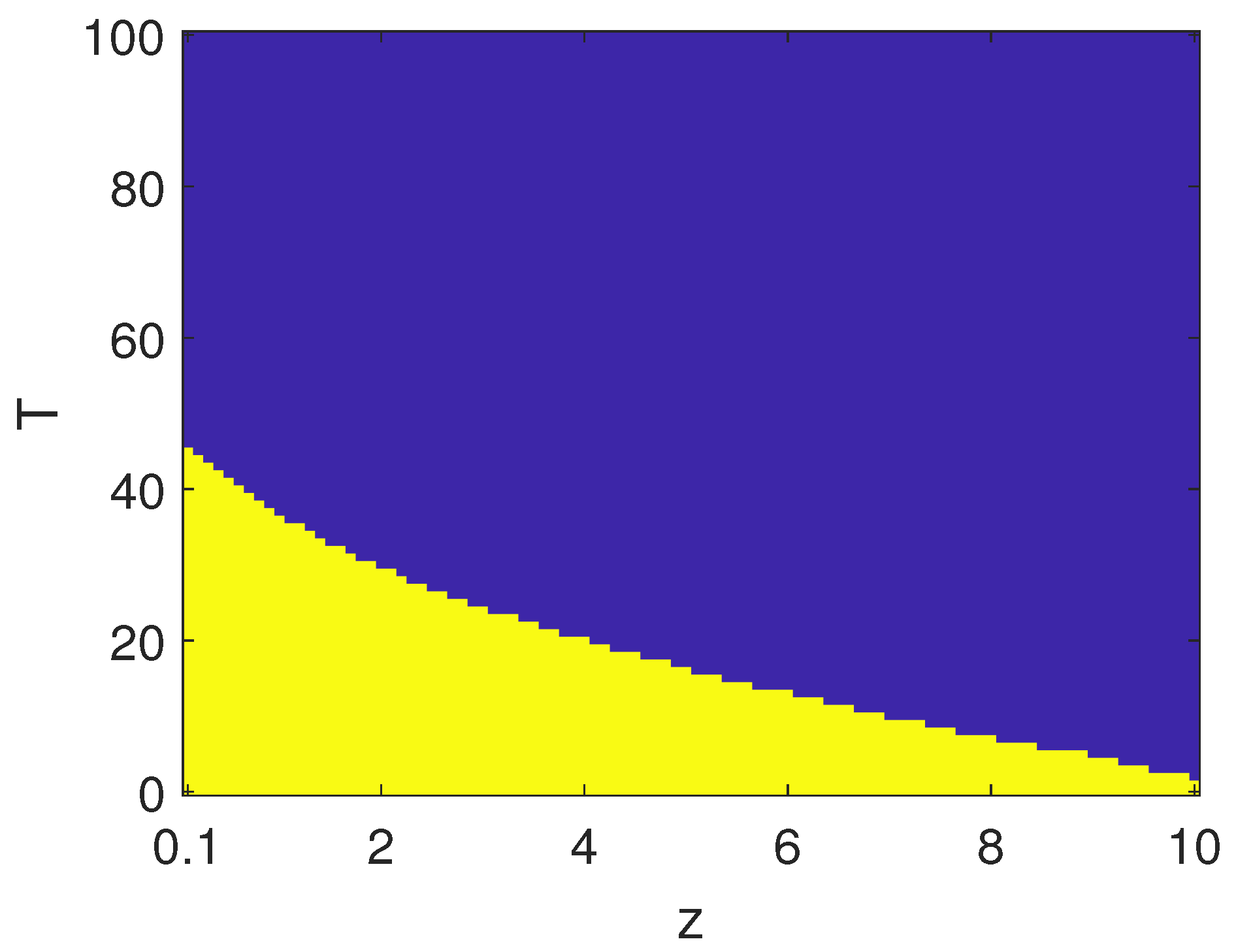
In order to further characterize the effectiveness of the control strategy, we also investigated the role of parameter z. Increasing z, generally led to longer transients in a closed-loop, as shown in Figure 10, where . The effect of time-delay, which may have led to instability, could be still mitigated by varying the gain k. The map reported in Figure 11 shows a positive effect linked to increasing z; the stability region in the parameter space was sensibly increased, leading in particular to an open region for small delays.
Finally, we characterized the effectiveness of the control system when the gain was fixed as and , and the position of the zero z was varied. In Figure 12 and Figure 13, the stability region in the parameter space was characterized. The control strategy failed to stabilize the error dynamics for larger zeros.
5. Analysis of Economic Impact and Competitive Advantages
In the market of medical robots, also including KUKA robot applications, high-performance impressive equipment for delicate surgical operations are common today, despite their high cost, which is justified by the specificity of their use. Indeed, the use of robots in low-cost diagnosis equipment, like ultrasound scanners, represents a field of application not approached until now, despite that it would provide a wide and low-cost impact. Having cheap remotely operating equipment working in two different parts of the world, along with the virtual man–machine controlled interface, would make ultrasound scanners highly reliable, as physicians with high skills could perform a complete remote analysis of the information.
The perspective of this application is appealing as it would facilitate access to the best possible expertise in every corner of the world, including military fields hospitals. The application has a quite immediate place in the market, as standard medical equipment and available KUKA robots have been adopted and already certified for clinical use. Until now, force feedback control for ultrasound remote applications, intended as a direct sensory feedback to the physician’s hand, was not yet available, even if this would be highly appreciated by physicians. The critical issue is the artificial body commercialization, which would be not expensive following the proposed project.
The conception of an active artificial body will also be very useful for educational purposes, and, therefore, the project could also be a suitable starting point for remote educational projects with a high innovation perspective. In this way, the diffusion of the equipment in the market will be further shortened.
6. Conclusions
The key elements of this contribution are related to the state of the art on biomedical robots for remote diagnostic assistance to introduce a proof-of-concept of a novel way to consider force feedback in remote clinical operations. In particular, we focused on proposing the use of KUKA robots for ultrasound scan application in remote control. The main components of this study were the following:
- 1.
- An artificial body conception with reactive force behavior to directly provide the response of the tissues of the remotely located patient on the physician’s hand.
- 2.
- The low cost ultrasound equipment.
- 3.
- The robot KUKA.
- 4.
- The distributed sensory network using qualitative measurement strain gage-based devices.
- 5.
- The control system based on a robust control technique.
A simplified mathematical model of the system was presented to determine the appropriate compensator to be used. The preliminary numerical results allowed us to assess the validity of the proposed control scheme, even in presence of time-delays. The control scheme was based on the stabilization of the error dynamics derived from the difference between the displacements retrieved in the two systems, and . An approach based on the linearization of the system led to the synthesis of two cascaded zero-pole networks. The effectiveness of this control scheme was verified by varying the design parameters defining the zero-pole network and the corresponding gain, with respect to the different time-delays acting on the transmission of the displacement sensed on system and transferred to .
The main aim of this research was, therefore, to construct a low-cost medical diagnostic system based on ultrasound sensors including force reactive behavior due to robust control feedback acting on an artificial body. This would provide a medical doctor with a higher level of information during remote controlled ultrasound scanning.
We remarked on the various problems that arise both regarding the implementation of the system and regarding the analytic point of view. The control system design for the linearized dynamics is highly complex due to the real case uncertainties and due to the delays that require accurate and robust analysis. This was considered in this paper by means of several numerical simulations. These results pave the way for the future progress of the project.
Author Contributions
Conceptualization, M.B. and L.F.; methodology, M.B., A.B., L.F. and S.G.; validation, M.B., A.B., L.F. and S.G.; formal analysis, M.B., A.B., L.F. and S.G.; investigation, M.B., A.B., L.F. and S.G.; data curation, M.B., A.B., L.F. and S.G.; writing—original draft preparation, A.B. and S.G.; writing—review and editing, M.B., A.B., L.F. and S.G.; supervision, M.B., A.B., L.F. and S.G. All authors have read and agreed to the published version of the manuscript
Funding
This research received no external funding.
Acknowledgments
The authors wish to acknowledge the contribution of the students of the Master Degree in Automation Engineering and Control of Complex Systems at the University of Catania.
Conflicts of Interest
The authors declare no conflict of interest.
References
- Swerdlow, D.R.; Cleary, K.; Wilson, E.; Azizi-Koutenaei, B.; Monfaredi, R. Robotic arm–assisted sonography: Review of technical developments and potential clinical applications. Am. J. Roentgenol. 2017, 208, 733–738. [Google Scholar] [CrossRef] [PubMed]
- Masuda, K.; Tateishi, N.; Suzuki, Y.; Kimura, E.; Wie, Y.; Ishihara, K. Experiment of wireless tele-echography system by controlling echographic diagnosis robot. In International Conference on Medical Image Computing and Computer-Assisted Intervention; Springer: Berlin/Heidelberg, Germany, 2002. [Google Scholar]
- Krebs, H.I.; Palazzolo, J.J.; Dipietro, L.; Ferraro, M.; Krol, J.; Rannekleiv, K.; Hogan, N. Rehabilitation robotics: Performance-based progressive robot-assisted therapy. Auton. Robot. 2003, 15, 7–20. [Google Scholar] [CrossRef]
- Priester, A.M.; Natarajan, S.; Culjat, M.O. Robotic ultrasound systems in medicine. IEEE Trans. Ultrason. Ferroelectr. Freq. Control 2013, 60, 507–523. [Google Scholar] [CrossRef] [PubMed]
- Salcudean, S.E.; Bell, G.; Bachmann, S.; Zhu, W.H.; Abolmaesumi, P.; Lawrence, P.D. Robot-assisted diagnostic ultrasound–design and feasibility experiments. In Proceedings of the International Conference on Medical Image Computing and Computer-Assisted Intervention, Cambridge, UK, 19–22 September 1999; Springer: Berlin/Heidelberg, Germany, 1999; pp. 1062–1071. [Google Scholar]
- Salcudean, S.E.; Bell, G.S.; Lawrence, P.D.; Marko, A.; Jameson, M. Robotically Assisted Medical Ultrasound. U.S. Patent No. 6,425,865, 30 July 2002. [Google Scholar]
- Gonzales, A.V.; Cinquin, P.; Troccaz, J.; Guerraz, A.; Hennion, B.; Pellissier, F.; Vieyres, P. TER: A system for robotic tele-echography. In Proceedings of the International Conference on Medical Image Computing and Computer-Assisted Intervention, Utrecht, The Netherlands, 14–17 October 2001; Springer: Berlin/Heidelberg, Germany, 2001; pp. 326–334. [Google Scholar]
- Tang, Q.; Liu, S.; Shang, L.; Li, Y. Design of teleoperation system of KUKA industrial robot and the control algorithm with heterogeneous master/slave structure. J. Sichuan Univ. (Eng. Sci. Ed.) 2016, 48, 180–185. [Google Scholar]
- Shahiduzzaman, M.; Kowalkiewicz, M.; Barrett, R. State of the State: 2017 Environmental Sensing; Chair in Digital Economy: Brisbane, Australia, 2018; Unpublished.
- Mathiassen, K.; Fjellin, J.E.; Glette, K.; Hol, P.K.; Elle, O.J. An ultrasound robotic system using the commercial robot UR5. Front. Robot. AI 2016, 3, 1. [Google Scholar] [CrossRef] [Green Version]
- Fjellin, J.E. Design of a Bilateral Master-Slave System with Haptic Feedback for Ultrasound Examinations. Master’s Thesis. 2013. Available online: https://www.duo.uio.no/handle/10852/37456 (accessed on 29 June 2020).
- Arbeille, P.; Ayoub, J.; Kieffer, V.; Ruiz, P.; Combes, B.; Coitrieux, A.; Perrotin, F. Realtime tele-operated abdominal and fetal echography in 4 medical centres, from one expert center, using a robotic arm & ISDN or satellite link. In Proceedings of the 2008 IEEE International Conference on Automation, Quality and Testing, Robotics, Cluj-Napoca, Romania, 22–25 May 2008; Volume 1, pp. 45–46. [Google Scholar]
- Bruyere, F.; Ayoub, J.; Arbeille, P. Use of a telerobotic arm to perform ultrasound guidance during renal biopsy in transplant recipients: A preliminary study. J. Endourol. 2011, 25, 231–234. [Google Scholar] [CrossRef] [PubMed]
- Elek, R.; Nagy, T.D.; Nagy, D.A.; Takács, B.; Galambos, P.; Rudas, I.; Haidegger, T. Robotic platforms for ultrasound diagnostics and treatment. In Proceedings of the 2017 IEEE International Conference on Systems, Man, and Cybernetics (SMC), Banff, AB, Canada, 5–8 October 2017; pp. 1752–1757. [Google Scholar]
- Wang, S.; Housden, J.; Noh, Y.; Singh, A.; Back, J.; Lindenroth, L.; Liu, H.; Hajnal, J.; Althoefer, K.; Singh, D.; et al. Design and implementation of a bespoke robotic manipulator for extra-corporeal ultrasound. JoVE (J. Vis. Exp.) 2019, 143, e58811. [Google Scholar] [CrossRef] [PubMed]
- Wang, S.; Housden, R.J.; Noh, Y.; Singh, A.; Lindenroth, L.; Liu, H.; Althoefer, K.; Hajnal, J.; Singh, D.; Rhode, K. Analysis of a Customized Clutch Joint Designed for the Safety Management of an Ultrasound Robot. Appl. Sci. 2019, 9, 1900. [Google Scholar] [CrossRef] [Green Version]
- Lindenroth, L.; Housden, R.J.; Wang, S.; Back, J.; Rhode, K.; Liu, H. Design and integration of a parallel, soft robotic end-effector for extracorporeal ultrasound. IEEE Trans. Biomed. Eng. 2019. [Google Scholar] [CrossRef] [PubMed] [Green Version]
- Tsumura, R.; Iwata, H. Robotic fetal ultrasonography platform with a passive scan mechanism. Int. J. Comput. Assist. Radiol. Surg. 2020, 1–11. [Google Scholar] [CrossRef] [PubMed]
- Available online: https://www.engineering.com/AdvancedManufacturing/ArticleID/15570/KUKAs-Medical-Robot-Ready-to-Scrub\protect\discretionary{\char\hyphenchar\font}{}{}In.aspx (accessed on 29 June 2020).
- Available online: https://studentiunict-my.sharepoint.com/:f:/g/personal/arturo_buscarino_unict_it/En7tWc7K3NZIkWjhEri0kfsBzh8ONIVFAQOdIYUuAyy-bQ?e=cYuCfI (accessed on 29 June 2020).
- Skalak, R.; Chien, S. (Eds.) Handbook of Bioengineering; McGraw-Hill: New York, NY, USA, 1987; p. 85. [Google Scholar]
- Fortuna, L.; Frasca, M. Optimal and Robust Control: Advanced Topics with MATLAB; CRC Press: London, UK, 2012. [Google Scholar]
- Hadjikov, L.; Kirilova, M.; Stoytchev, S.; Pashkouleva, D. Visco-elastic mechanical behaviour of human abdominal fascia. Ser. Biomech. 2007, 23, 43–51. [Google Scholar]
- Gu, K.; Chen, J.; Kharitonov, V.L. Stability of Time-Delay Systems; Springer Science & Business Media: Berlin, Germany, 2003. [Google Scholar]
- Belhamel, L.; Fortuna, L.; Xibilia, M.G. A numerical procedure to obtain the pseudo-polynomial characteristic equation of a commensurate time-delay system. In Proceedings of the 2019 International Symposium on Signals, Circuits and Systems (ISSCS), Iasi, Romania, 11–12 July 2019; pp. 1–4. [Google Scholar]
Figure 1.
(a) Schematics of the proposed remote ultrasound scan setup. (b) Structure of he artificial body.
Figure 1.
(a) Schematics of the proposed remote ultrasound scan setup. (b) Structure of he artificial body.
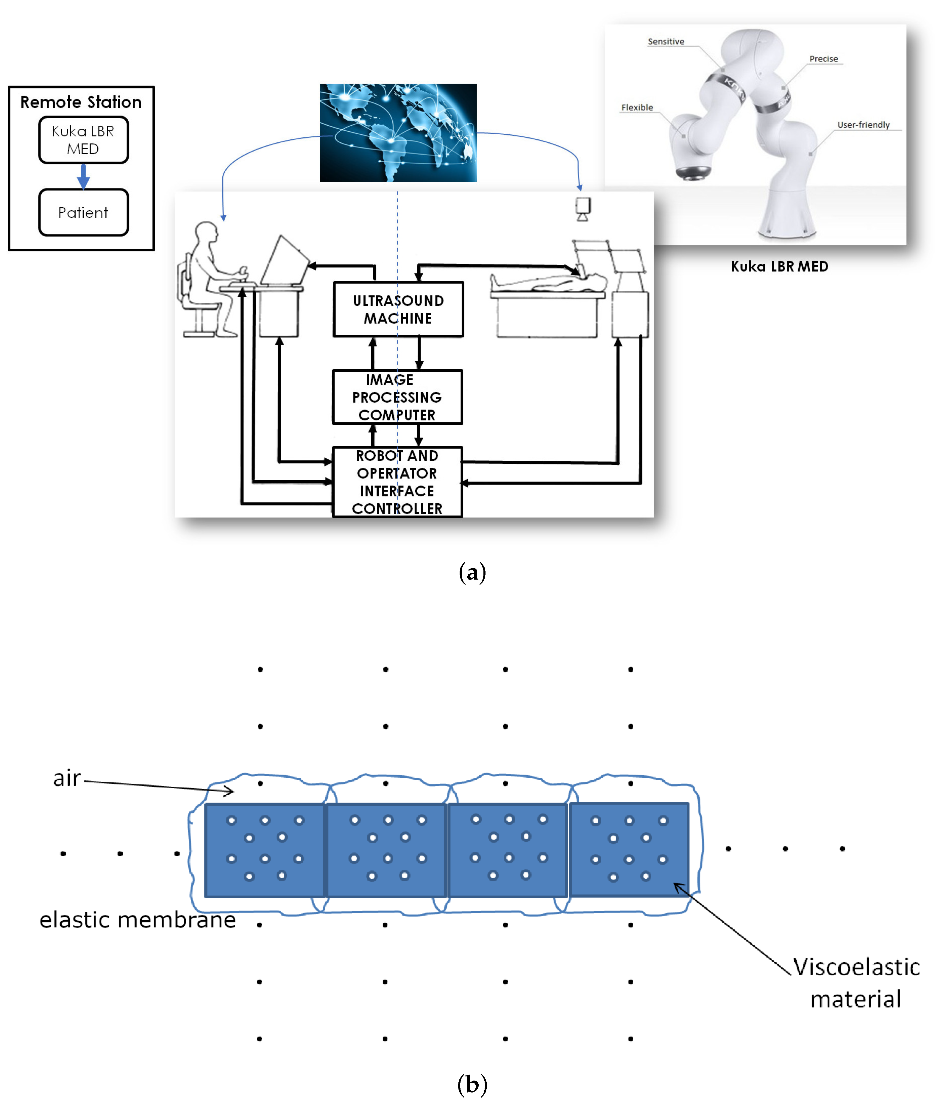
Figure 2.
Schematic representation of demo 1.

Figure 3.
Implementation of demo 1: On the left is the strain gauge, representing the patient station; on the right is the electromagnet representing the artificial body on which the physician uses his probe. The time-scales are in the order of a few seconds.
Figure 3.
Implementation of demo 1: On the left is the strain gauge, representing the patient station; on the right is the electromagnet representing the artificial body on which the physician uses his probe. The time-scales are in the order of a few seconds.

Figure 4.
Experimental evaluation of demo 2: the two stations are linked through an Arduino microcontroller implementing the control action and the transmission delay. (a,b) The actuator pushes the foam with different intesities, (c) complete setup with the two actuators representing the local and remote station performing the same pressure thanks to the control action. The time-scales are in the order of a few seconds.

Figure 5.
The linear solid standard model.
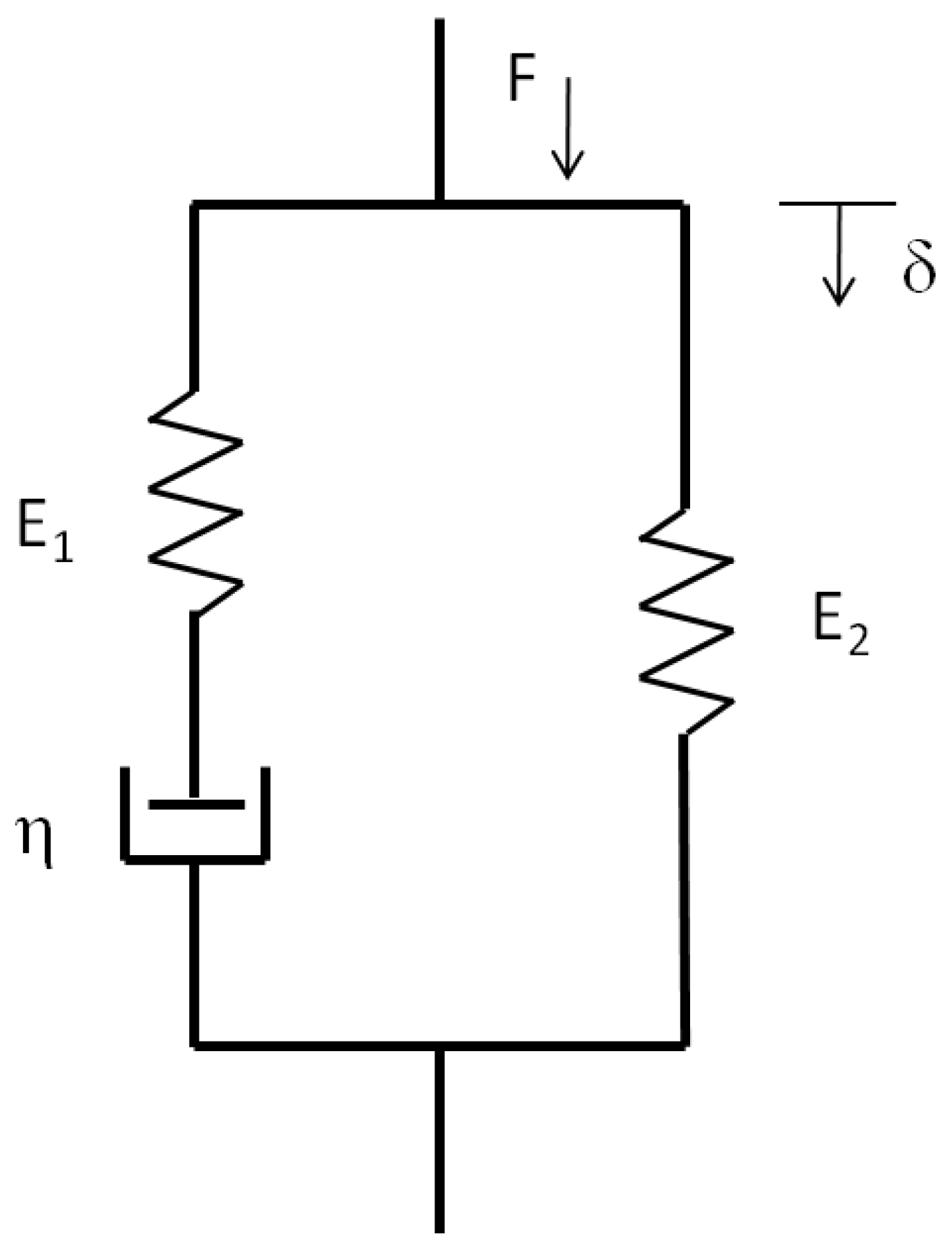
Figure 6.
The control scheme.
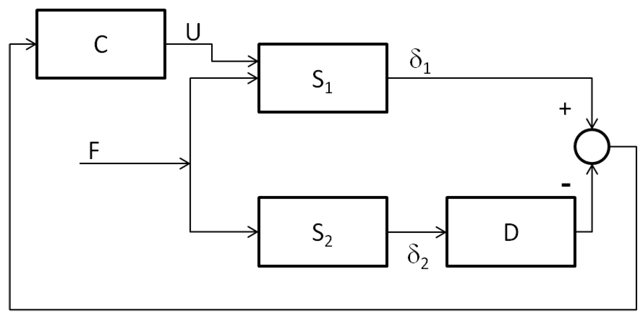
Figure 7.
The linearized feed-forward control model.
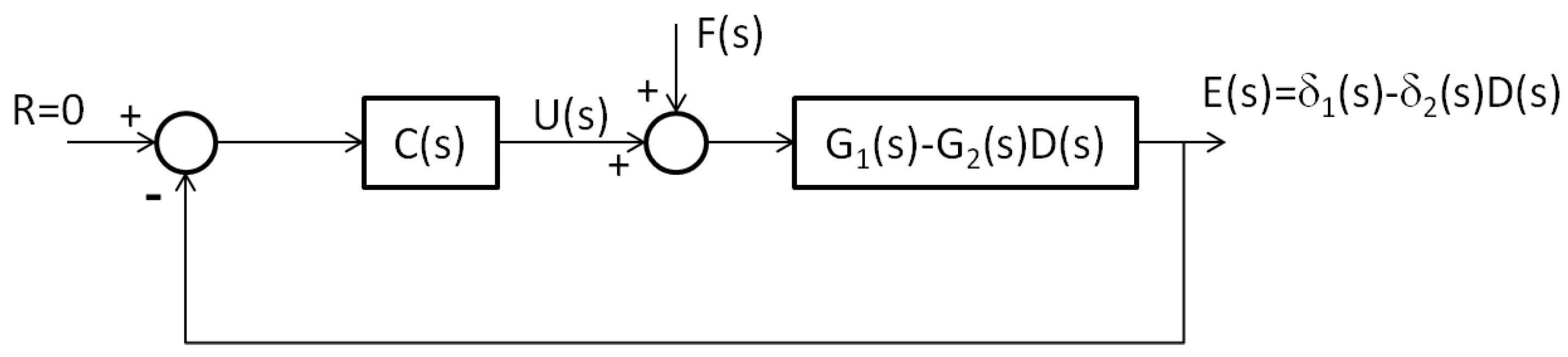
Figure 8.
Numerical results: (a) , ; (b) , ; (c) , . The parameters of the systems are chosen as: , , , , , .
Figure 8.
Numerical results: (a) , ; (b) , ; (c) , . The parameters of the systems are chosen as: , , , , , .
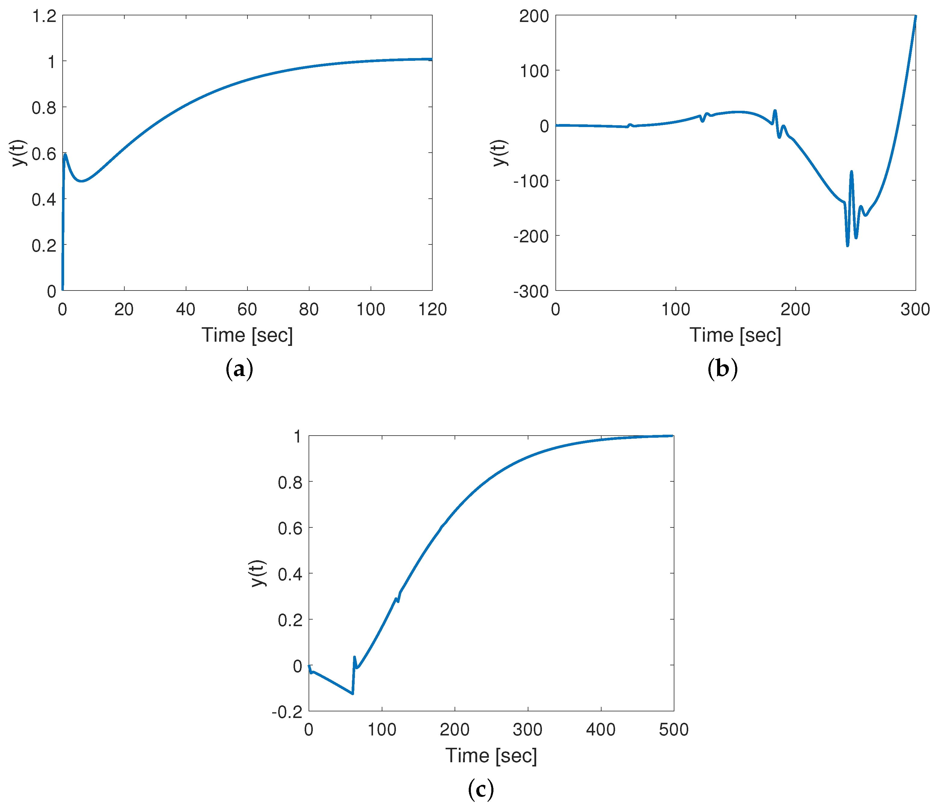
Figure 9.
Boundary in the parameter space between the stability (yellow) and instability (blue) regions, for . Other parameters as reported in the caption of Figure 8.
Figure 9.
Boundary in the parameter space between the stability (yellow) and instability (blue) regions, for . Other parameters as reported in the caption of Figure 8.
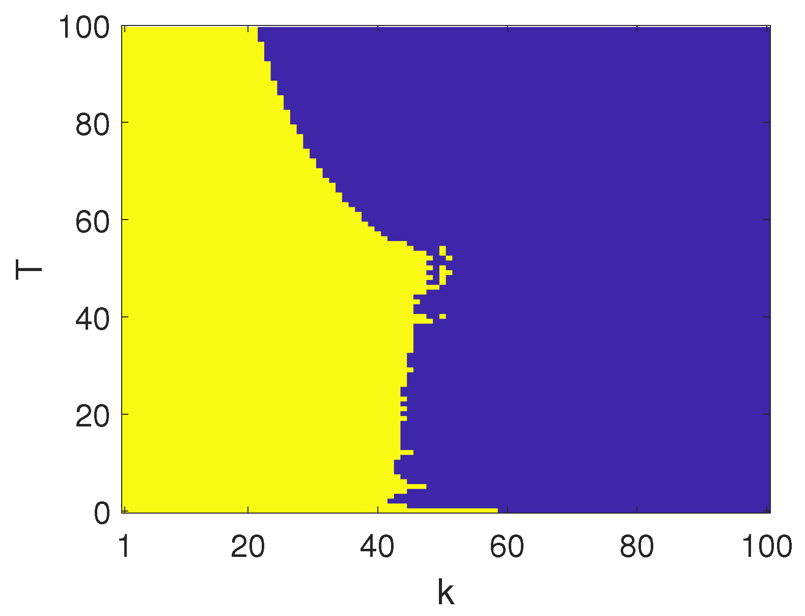
Figure 10.
Numerical results: (a) , ; (b) , ; (c) , . The parameters of the systems are chosen as: , , , , , .
Figure 10.
Numerical results: (a) , ; (b) , ; (c) , . The parameters of the systems are chosen as: , , , , , .
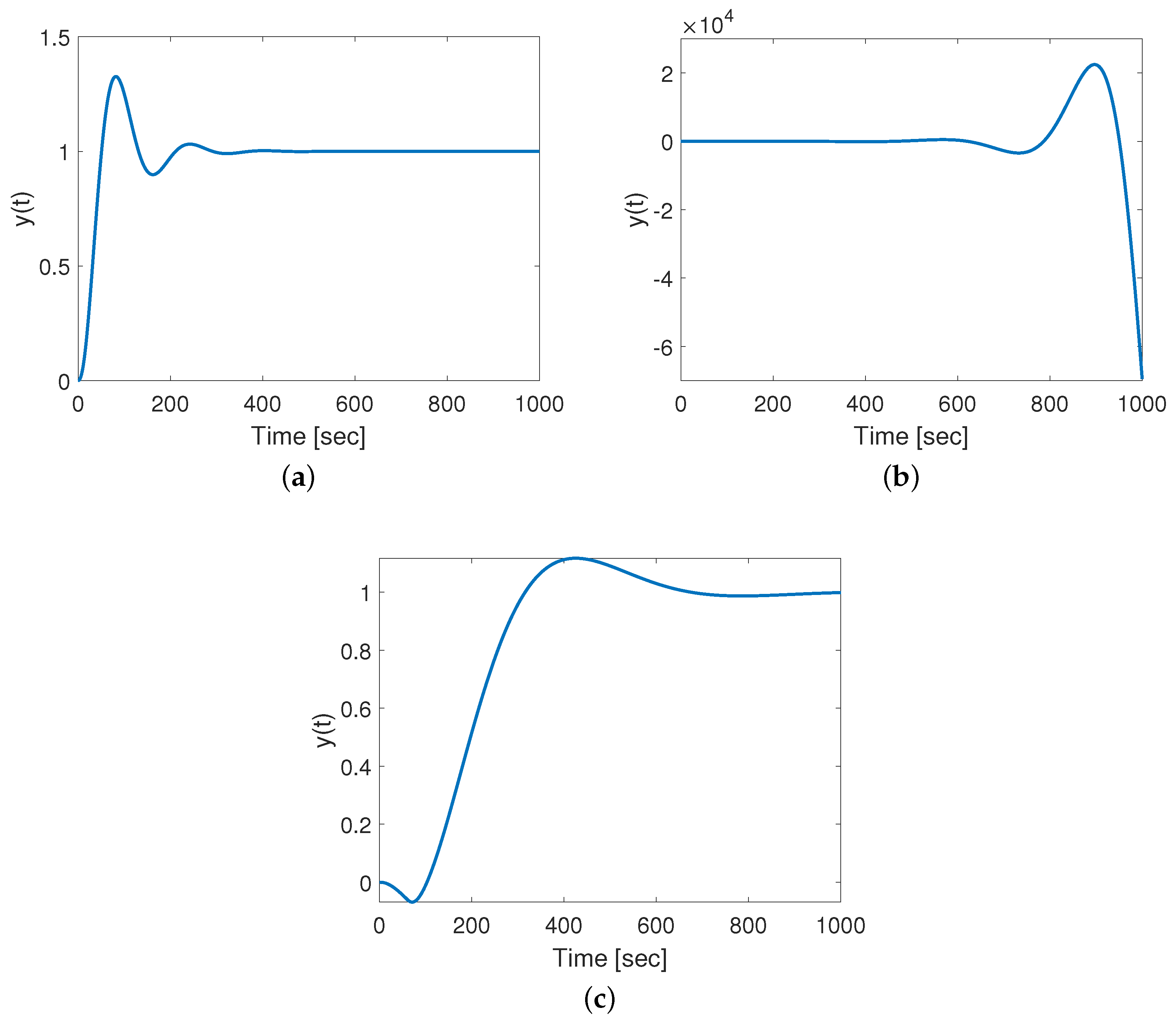
Figure 11.
The boundary in the parameter space between the stability (yellow) and instability (blue) regions, for . Other parameters are as reported in the caption of Figure 8.
Figure 11.
The boundary in the parameter space between the stability (yellow) and instability (blue) regions, for . Other parameters are as reported in the caption of Figure 8.
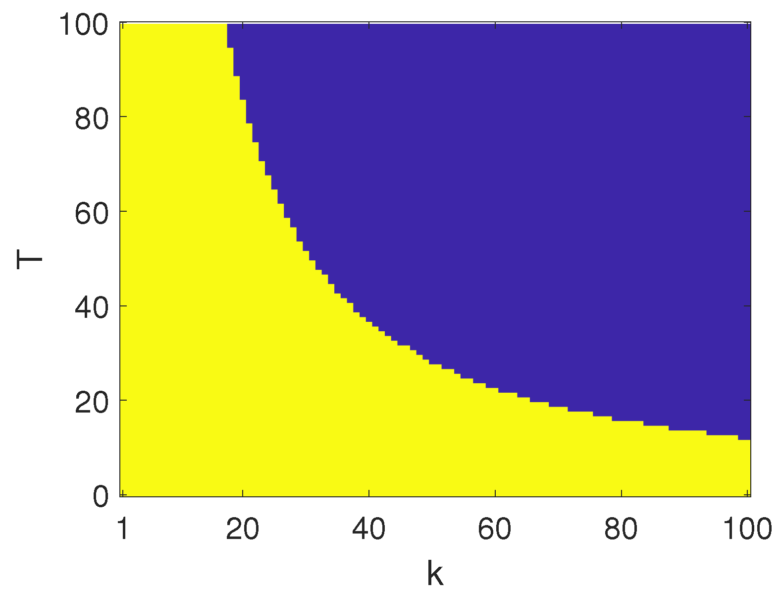
Figure 12.
The boundary in the parameter space between the stability (yellow) and instability (blue) regions, for . Other parameters are as reported in the caption of Figure 8.
Figure 12.
The boundary in the parameter space between the stability (yellow) and instability (blue) regions, for . Other parameters are as reported in the caption of Figure 8.
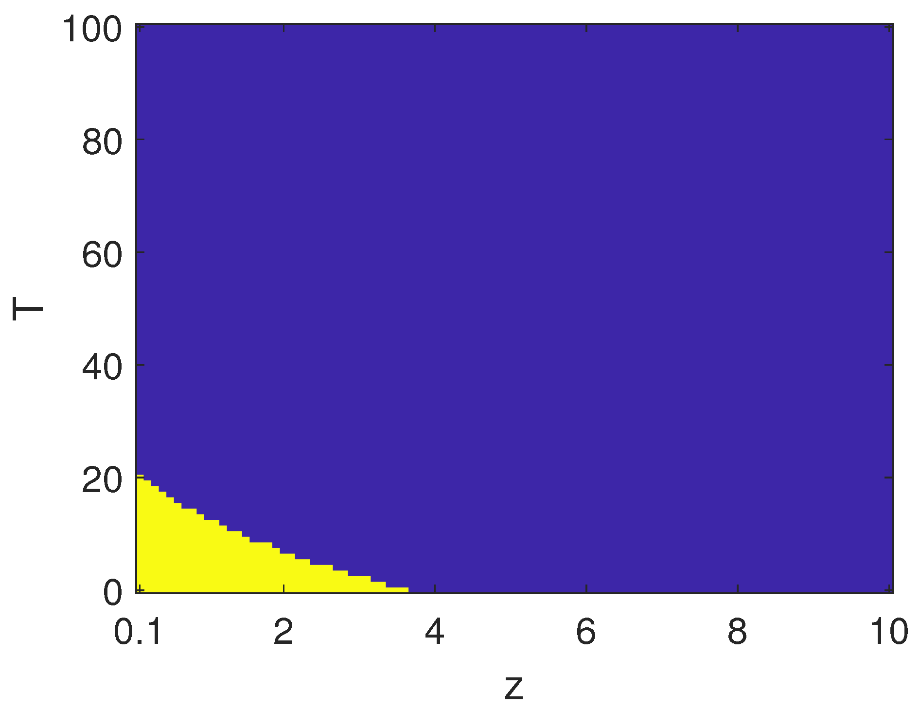
Figure 13.
The boundary in the parameter space between the stability (yellow) and instability (blue) regions, for . Other parameters are as reported in the caption of Figure 8.
Figure 13.
The boundary in the parameter space between the stability (yellow) and instability (blue) regions, for . Other parameters are as reported in the caption of Figure 8.
© 2020 by the authors. Licensee MDPI, Basel, Switzerland. This article is an open access article distributed under the terms and conditions of the Creative Commons Attribution (CC BY) license (http://creativecommons.org/licenses/by/4.0/).
Share and Cite
MDPI and ACS Style
Bucolo, M.; Buscarino, A.; Fortuna, L.; Gagliano, S. Force Feedback Assistance in Remote Ultrasound Scan Procedures. Energies 2020, 13, 3376. https://doi.org/10.3390/en13133376
AMA Style
Bucolo M, Buscarino A, Fortuna L, Gagliano S. Force Feedback Assistance in Remote Ultrasound Scan Procedures. Energies. 2020; 13(13):3376. https://doi.org/10.3390/en13133376
Chicago/Turabian StyleBucolo, Maide, Arturo Buscarino, Luigi Fortuna, and Salvina Gagliano. 2020. "Force Feedback Assistance in Remote Ultrasound Scan Procedures" Energies 13, no. 13: 3376. https://doi.org/10.3390/en13133376
Note that from the first issue of 2016, this journal uses article numbers instead of page numbers. See further details here.