Article

A Hot Water Split-Flow Dual-Pressure Strategy to Improve System Performance for Organic Rankine Cycle

School of Mechanical Engineering, Southwest Jiaotong University, Chengdu 610031, China
*
Author to whom correspondence should be addressed.
Energies 2020, 13(13), 3345; https://doi.org/10.3390/en13133345
Submission received: 4 June 2020 / Revised: 22 June 2020 / Accepted: 29 June 2020 / Published: 30 June 2020
(This article belongs to the Section J: Thermal Management)

Abstract

:
The organic Rankine cycle (ORC) is widely used to recover industrial waste heat. For an ORC system using industrial waste hot water as a heat source, a novel hot water split-flow dual-pressure organic Rankine cycle (SFD-ORC) system is developed to improve the performance of the ORC. The maximum net power output was selected to compare three ORC systems, including basic ORC (B-ORC), conventional dual-pressure ORC (CD-ORC) and SFD-ORC. A genetic algorithm (GA) was used to optimize the parameters to search the maximum net power output of ORCs. The maximum net output power was taken as the standard of performance evaluation. The results show that, under the same hot water inlet temperature condition, the optimal hot water outlet temperature of B-ORC is much higher than that of CD-ORC and SFD-ORC, which indicates that less thermal energy could be utilized to convert to power in B-ORC. The optimal hot water temperature at the outlet of evaporator 1 in SFD-ORC is higher than that in CD-ORC, which means SFD-ORC could make more efficient use of the high-grade thermal energy of hot water. The SFD-ORC could obtain the highest net output power under the optimal parameter conditions, followed by the CD-ORC system, while the B-ORC has the lowest net output power. Moreover, with the increase in the hot water inlet temperature, the advantage of SFD-ORC becomes increasingly obvious. When the hot water inlet temperature is 90 °C, the net output power of SFD-ORC at is 6.22% higher than that of CD-ORC. The net output power of SFD-ORC at 130 °C increases to 9.7% higher than that of CD-ORC. The SFD-ORC presents better system performance and has great engineering application potential.

1. Introduction

Industrial waste heat recovery technology has attracted great attention because it has great potential in reducing fuel consumption and environmental pollution. Common industrial waste heat utilization technologies include regenerators, heat pumps, heat recovery steam generators, organic Rankine cycle (ORC), Kalina Cycle, etc [1,2]. The ORC system is an excellent performance system to recover industrial waste heat in order to generate electric energy or output mechanical power [3,4,5].
The components of the ORC system were investigated to improve the system performance. The structure of the heat exchanger was calculated to investigate its economic influence on the ORC system in a Belgian geothermal project [6,7,8]. It was concluded that an ORC system with a mechanical ventilation cooling tower is more economical than that with an air-cooled condenser. Usman et al. [9] carried out an economic analysis on the ORC system in different geographical locations. Haghprarst et al. discussed the different energy and exergy metric of ORC with an integrated ejector [10]. Zhang et al. [11] compared the maximum net output power between an ORC system with an ejector and a basic organic Rankine cycle system. Rathod [12] designed a controller for an ORC system to obtain the maximum power. Li et al. [13] proved that ORC pump speed is an important parameter affecting ORC performance, using a series of experimental tests. Li et al. [14] developed an optimized condensation system to improve the performance of the condenser.
Some researchers discussed methods to optimize the configuration of the ORC system. Li et al. [15,16,17] studied three ORC systems using geothermal water as the heat source. Wang et al. [18] investigated a two-stage ORC system with double heat sources. Tang [19] presented two ORC application cases in refineries to compare cascade ORC and basic ORC systems. Using a thermodynamic method, Yari [20] studied six different ORC models for high-temperature geothermal power plants. Rashwan et al. [21] found that ORC coupled with a cascade cycle shows an increase of 73% in net output power, while the energy efficiency and exergy efficiency are enhanced. Li et al. [22] studied some effects on the limited temperature of the heat source. Cayer et al. [23] optimized a transcritical ORC using the maximum net output work as the objective. Wang et al. [24] focused on comparison of subcritical ORC, dual-pressure (DORC) and transcritical ORC (TORC), adopting several different working fluids to recover low-grade energy. Yu et al. [25] proposed a trilateral cycle combined with the organic Rankine cycle system to improve system performance.
Many studies investigated the optimization algorithm for different ORC configurations to improve the thermal efficiency of heat recovery. Xi et al. [26] used a genetic algorithm (GA) to optimize the operating conditions for three ORC systems using six different working fluids. Palagi et al. [27] proposed an ORC performance optimization method using a multi-objective optimal neural network model. Kim et al. [28] conducted a series of experiments for the radial turbine of ORC and developed a deep neural network to predict their experimental data. Zhao et al. [29] designed a PSO for the optimization of an engine–ORC combined system. Ochoa et al. [30] used the PSO algorithm to analyze the thermoeconomy of ORC, RORC and DORC, and concluded that the DORC system performance can be improved to a greater extent. Özkaraca et al. [31] studied the maximum exergy efficiency by simulating the actual air-cooled ORC binary geothermal power plant using an artificial bee colony (ABC) algorithm. Dong et al. [32] explored the potential of SVM-RBF (Support Vector Machine Gauss Radial Basis kernel function), SVM-LF (Support Vector Machine linear function) and BP-ANN (Back Propagation Artificial Neural Network) to predict the performance of an ORC system.
It should be noted that the configuration of the heat source side was not investigated in any studies. However, it could be optimized to improve the system performance of the ORC system. Therefore, the hot water split-flow dual-pressure ORC (SFD-ORC) system was proposed in this paper. Compared with the conventional dual-pressure ORC (CD-ORC), the hot water splits into two flow directions in SFD-ORC to make more efficient use of high-grade thermal energy and obtain more net output power. By taking the maximum net power output as the objective, a comparison of three ORCs including basic ORC, conventional dual-pressure ORC and the split-flow dual-pressure ORC was discussed. The genetic algorithm was used to optimize the parameters of ORCs to find the maximum net power output.

2. System Description

2.1. Basic ORC System

The basic ORC (B-ORC) system is made from an evaporator, a preheater, a pump, a condenser, an expander and a generator. The schematic and theoretical T-s diagrams of the B-ORC system are shown in Figure 1. The green line represents the flow direction of the working fluid. The red line a–c represents the flow direction of the industrial waste hot water. The blue line m–n represents the flow direction of the cooling water. The green line stands for the flow direction of the working fluid.

2.2. Conventional Dual-Pressure ORC System

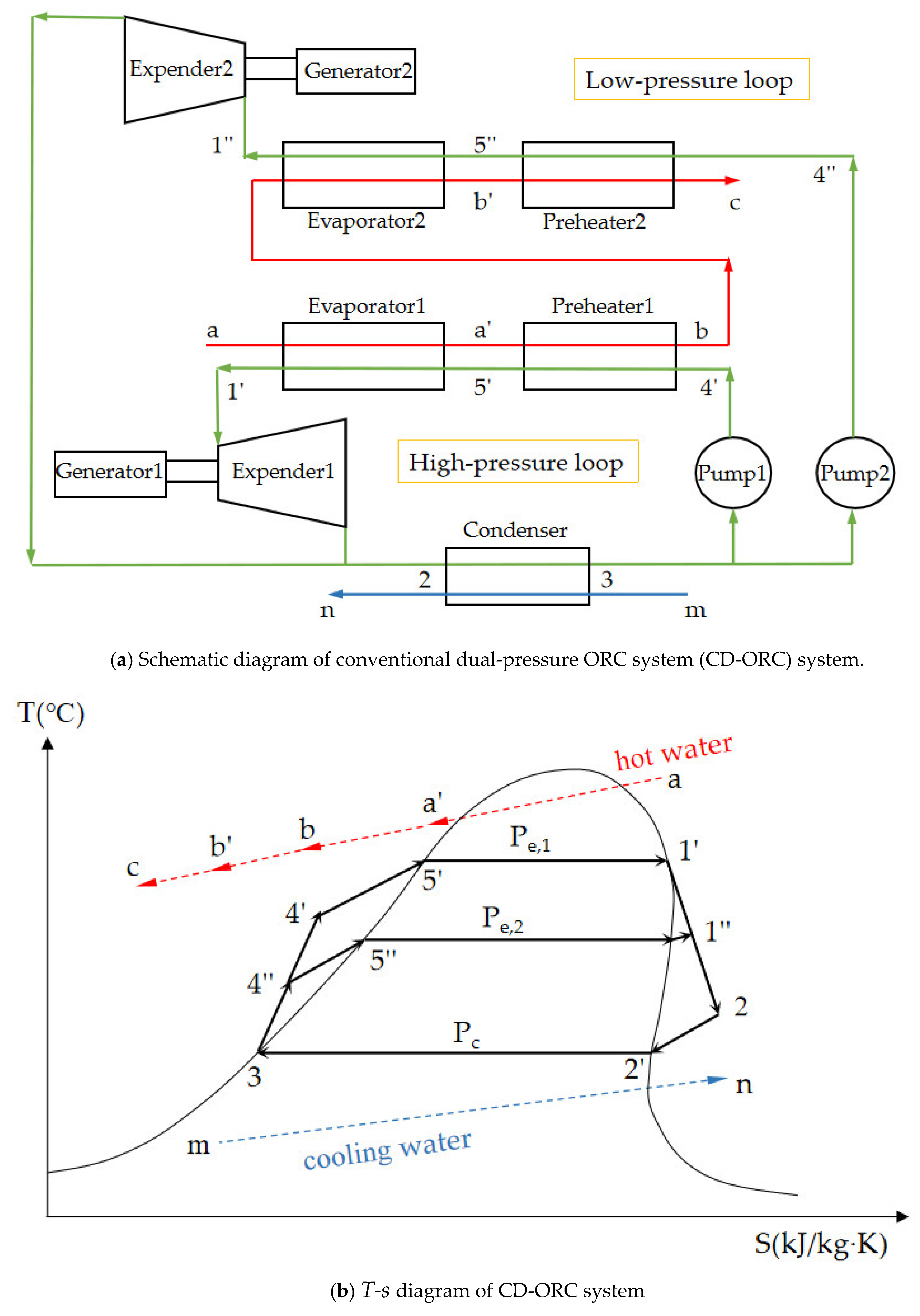
The dual-pressure ORC system is widely used to improve the performance of ORC. Figure 2 shows the schematic diagram and the T-s diagram of a conventional dual-pressure ORC (CD-ORC) system. From Figure 2a, it can be observed that CD-ORC consists of a high-pressure loop and low-pressure loop. The green line represents the flow direction of the working fluid. The red line represents the flow direction of hot water. The blue line m–n stands for the flow direction of cooling water.

2.3. Split-Flow Dual-Pressure ORC System

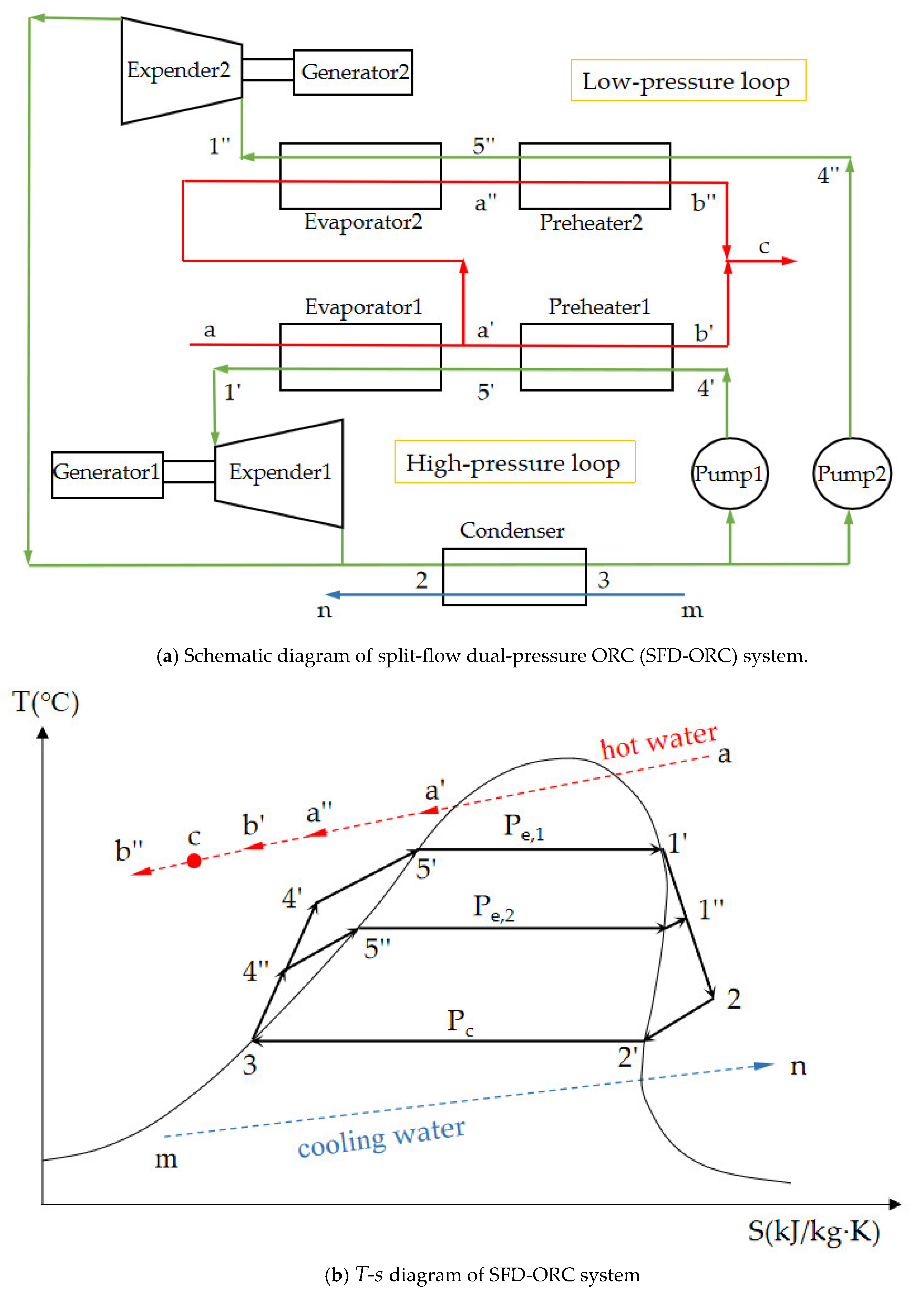
In order to make more effective use of high-grade heat sources to obtain more net output power, the split-flow dual-pressure ORC (SFD-ORC) system was proposed in this paper. Figure 3 shows the schematic diagram and the T-s diagram. Compared with CD-ORC, the hot water split into two flow directions at the outlet of evaporator 1 in the SFD-ORC system. Obviously, the temperature of hot water at the inlet of evaporator 2 in SFD-ORC is higher than that in CD-ORC, due to the fact that the hot water flowing into evaporator 2 has not been cooled by preheater 1. It means SFD-ORC could make more effective use of a high-grade heat source than CD-ORC. The configuration of SFD-ORC is similar to that of CD-ORC, which also consists of a high-pressure loop and low-pressure loop. The green line represents the flow direction of the working fluid. The red line represents the flow direction of hot water. The blue line m–n represents the flow direction of the cooling water.

3. Mathematical Model

3.1. Assumptions

The following assumptions are considered for the mathematical model:
  • The system operates under a steady state.
  • In the B-ORC system, the working fluid liquid at the outlet of the working fluid pump is heated to the saturated liquid in the preheater, and then the saturated liquid at the outlet of the preheater is heated to the saturated vapor in the evaporator. In the CD-ORC and SFD-ORC systems, the working fluid liquid at the outlet of the high-pressure working fluid pump or the low-pressure working fluid pump is heated to the saturated liquid state in the preheater of the corresponding loop, and then the saturated liquid at the outlet of the high-pressure preheater and the low-pressure preheater is heated to the saturated vapor in the evaporator of the corresponding loop.
  • The working fluid at the outlet of condenser is in a saturated liquid state.
  • The inlet temperature of the hot water and the cooling water are constant.
  • The changes in kinetic and potential energy are neglected.
  • The friction loss and energy loss in the evaporator, condenser and any pipeline are neglected.
  • The condensation temperature of the working fluid is constant.
  • The cooling water pump and working fluid pump have a constant isentropic efficiency and mechanical efficiency.
  • The expander has a constant isentropic efficiency and mechanical efficiency.

3.2. Thermodynamic Model

3.2.1. B-ORC System

The calculation method of each thermodynamic process in the B-ORC system can be expressed as follows:
  • The process from state 1 to 2
    h 2 = h 1 ( h 1 h 2 , s ) η exp , s
    W exp = m w f ( h 1 h 2 ) η exp
  • The process from state 2 to 3
    Q c o n d = m w f ( h 2 h 3 )
    m c w = Q c o n d c p ( t n t m )
    W c o n d = m c w Δ P c w p u m p / ( η c w p u m p ρ c w )
  • The process from state 3 to 4
    h 4 = h 3 + ( h 4 , s h 3 ) / η p u m p , s
    W p u m p = m w f ( h 4 h 3 ) / η p u m p
  • The process from state 4 to 5
    Q p r e = m h w ( h a h b )
    m w f = Q p r e h 5 h 4
  • The process from state 5 to 1
    t e v a p = t a t p i n
    Q e v a p = m h w ( h a h a )
    m w f = Q e v a p h 1 h 5
The net output power of the B-ORC system
W n e t , B O R C = W exp W c o n d W p u m p

3.2.2. CD-ORC System

The calculation method of each thermodynamic process in the CD-ORC system can be expressed as follows:
  • The process from state 1′ to 2
    h 2 = h 1 ( h 1 h 2 , s ) η exp , s
    W exp 1 = m w f 1 ( h 1 h 2 ) η exp
  • The process from state 1″ to 2
    h 2 = h 1 ( h 1 h 2 , s ) η exp , s
    W exp 2 = m w f 2 ( h 1 h 2 ) η exp
  • The process from state 2 to 3
    Q c o n d = m w f ( h 2 h 3 )
    m c w = Q c o n d c p ( t n t m )
    W c o n d = m c w Δ P c w p u m p / ( η c w p u m p ρ c w )
  • The process from state 3 to 4′
    h 4 = h 3 + ( h 4 , s h 3 ) / η p u m p , s
    W p u m p 1 = m w f 1 ( h 4 h 3 ) / η p u m p
  • The process from state 3 to 4″
    h 4 = h 3 + ( h 4 , s h 3 ) / η p u m p , s
    W p u m p 2 = m w f 2 ( h 4 h 3 ) / η p u m p
  • The process from state 4′ to 5′
    Q p r e 1 = m w f 1 ( h 5 h 4 )
    m h w = Q p r e 1 h a h b
  • The process from state 4″ to 5″
    Q p r e 2 = m h w ( h b h c )
    m w f 2 = Q p r e 2 h 5 h 4
  • The process from state 5′ to 1′
    t 5 = t a t p i n
    Q e v a p 1 = m h w ( h a h a )
    m w f 1 = Q e v a p 1 h 1 h 5
  • The process from state 5″ to 1″
    t 5 = t b t p i n
    Q e v a p 2 = m h w ( h b h b )
    m w f 2 = Q e v a p 2 h 1 h 5
The net output power of the CD-ORC system
W n e t , C D O R C = W exp 1 + W exp 2 W c o n d W p u m p 1 W p u m p 2

3.2.3. SFD-ORC System

The calculation method of each thermodynamic process in the SFD-ORC system can be expressed by the following equations:
  • The process from state 1′ to 2
    h 2 = h 1 ( h 1 h 2 , s ) η exp , s
    W exp 1 = m w f 1 ( h 1 h 2 ) η exp
  • The process from state 1″ to 2
    h 2 = h 1 ( h 1 h 2 , s ) η exp , s
    W exp 2 = m w f 2 ( h 1 h 2 ) η exp
  • The process from state 2 to 3
    Q c o n d = m w f ( h 2 h 3 )
    m c w = Q c o n d c p ( t n t m )
    W c o n d = m c w Δ P c w p u m p / ( η c w p u m p ρ c w )
  • The process from state 3 to 4′
    h 4 = h 3 + ( h 4 , s h 3 ) / η p u m p , s
    W p u m p 1 = m w f 1 ( h 4 h 3 ) / η p u m p
  • The process from state 3 to 4″
    h 4 = h 3 + ( h 4 , s h 3 ) / η p u m p , s
    W p u m p 2 = m w f 2 ( h 4 h 3 ) / η p u m p
  • The process from state 4′ to 5′
    Q p r e 1 = m w f 1 ( h 5 h 4 )
    m h w = Q p r e 1 h a h b
  • The process from state 4″ to 5″
    h b = m h w h c m h w h b m h w m h w
    Q p r e 2 = ( m h w m h w ) ( h a h b )
    m w f 2 = Q p r e 2 h 5 h 4
  • The process from state 5′ to 1′
    t 5 = t a t p i n
    Q e v a p 1 = m h w ( h a h a )
    m w f 1 = Q e v a p 1 h 1 h 5
  • The process from state 5″ to 1″
    t 5 = t a t p i n
    Q e v a p 2 = ( m h w m h w ) ( h a h a )
    m w f 2 = Q e v a p 2 h 1 h 5
The net output power of the SFD-ORC system
W n e t , S F D O R C = W exp 1 + W exp 2 W c o n d W p u m p 1 W p u m p 2

3.3. Solution

In order to carry out the numerical simulation, MATLAB [33] programs were compiled to solve the above equations. The simulation parameters and boundary conditions are shown in Table 1, while the inlets of hot water are variables for the optimization calculation. R245fa is selected as the working fluid and the thermodynamic properties of each state point can be calculated by REFPROP [34].

4. Genetic Algorithm Method Schemes

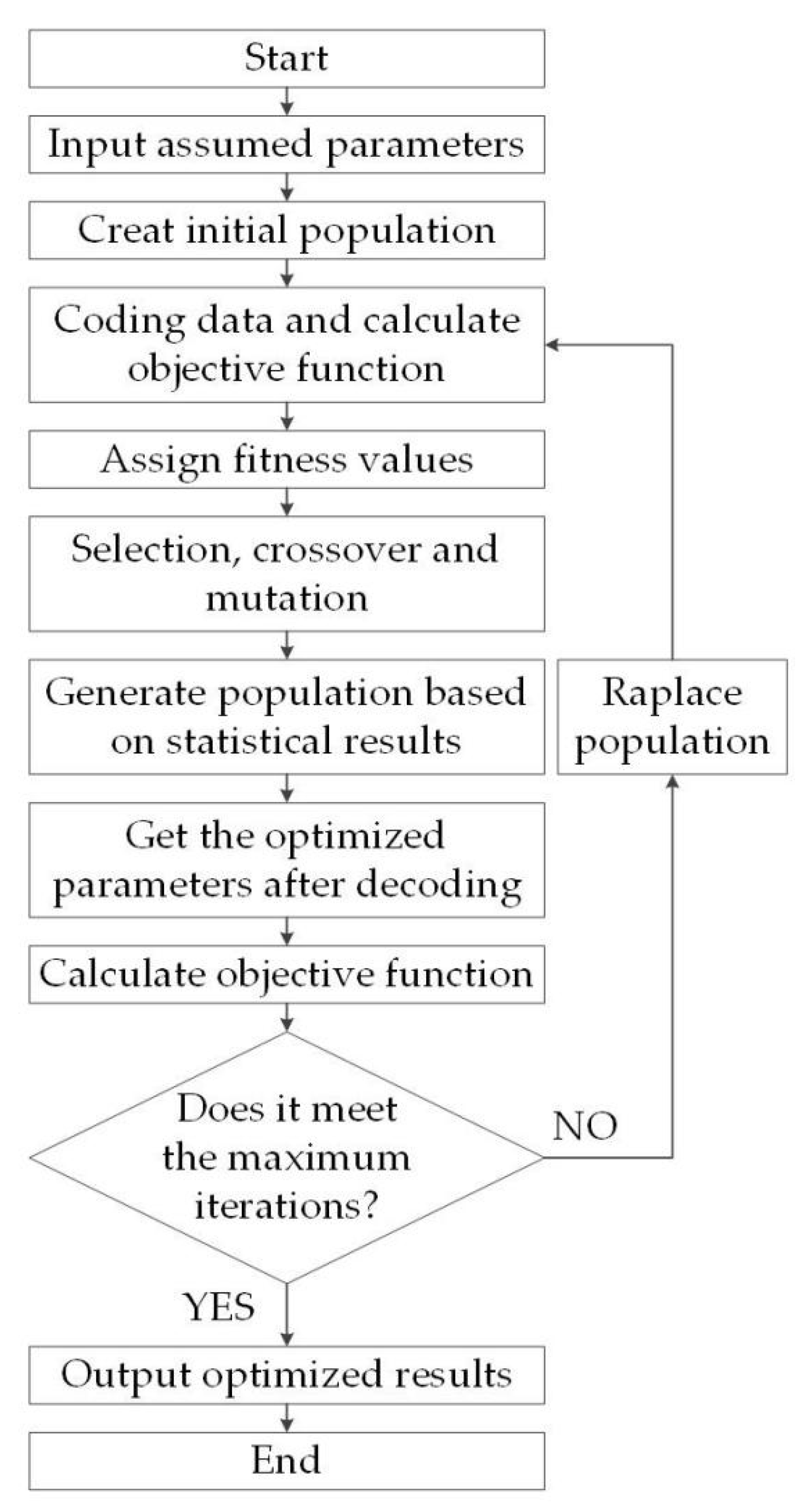
The optimization of B-ORC, CD-ORC and SFD-ORC were carried out using the genetic algorithm method (GA) and the net output power was chosen as the objective function. Genetic algorithms simulate the phenomenon of natural selection and heredity. The optimization process using the GA is illustrated in Figure 4.
The configuration of the GA consists of the population size, number of variables, precision of variables, objective function, maximum number of generations, field descriptor, selection method, crossover probability, mutation probability, and so on. The population size and maximum number of generations can evaluate the convergence of the genetic algorithm in practical problems. The number of variables refers to the variables of the objective function in the genetic algorithm for the proposed practical problems. The precision of the variables relates to binary digits corresponding to a variable, which was set as 20 in this paper. The field descriptor describes the numerical range, coding mode and other parameters of each variable. For selection method, the ’stochastic universal sampling (SUS)’ method was adopted as the fundamental of arithmetic. The crossover probability was set as 0.7, while the mutation probability was set as 0.01 [35]. More detailed information about the GAs are shown in Table 2.

5. Results and Discussion

5.1. Independent Parameters on Net Power Output

The independent parameters of the net power output of three ORC systems should be determined to provide the input variables for GA. According to the previous research [36], the net output power of B-ORC is related to the inlet temperature of hot water, ta, the pinch temperature difference of the evaporator, the evaporation temperature, tevap, and the condensation temperature, tcond. In general, the inlet temperature of hot water is an input condition for B-ORC, the condensation temperature is determined by the temperature of cooling water, and the pinch temperature difference is related to the construction of the evaporator. This means that the net power output of B-ORC is determined by the evaporation temperature, tevap, when the above three parameters are provided. Moreover, the outlet temperature of hot water, tc, is related to the evaporation temperature according to the principle of mass and energy conservation. Therefore, it could be deduced that the net power output of B-ORC could be determined by the outlet temperature of hot water, tc, as shown in Equation (59).
W n e t , O R C = f ( t c )
For CD-ORC and SFD-ORC, the net power output consists of two parts: that of the high-pressure loop and that of the low-pressure loop. According to the configurations presented in Section 2 and the thermodynamic model presented in Section 3, for those two dual-pressure ORC systems, ta′ could present the utilization amount of the thermal energy in the high-pressure loop. Therefore, the net power output of those two dual-pressure ORC systems is related to ta′ as well as tc, as shown in the following two equations.
W n e t , C D O R C = f ( t a , t c )
W n e t , S F D O R C = f ( t a , t c )

5.2. The Effect of Independent Parameters on Net Power Output

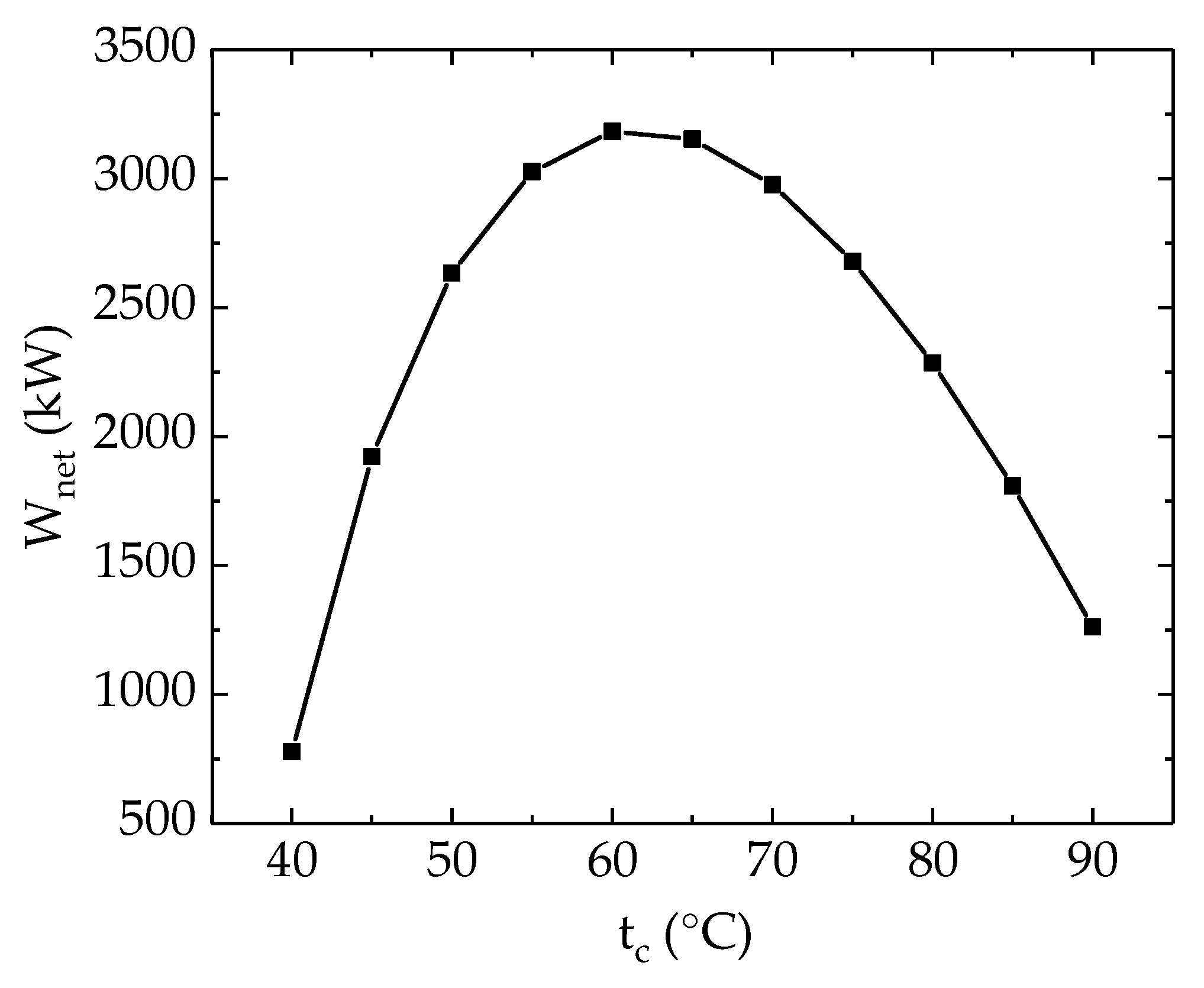
In this section, the effect of independent parameters on the net output power is discussed. The influence of the hot water outlet temperature tc on the net output power of the B-ORC system is shown as Figure 5 when ta is set to 100 °C. From Figure 5, the net output power increases first and then decreases with tc. The net output power reaches the maximum value when tc is 60 °C. It is proven that tc and net output power satisfy one-to-one correspondence, and there exists an optimal tc that makes net output power reach the maximum value.
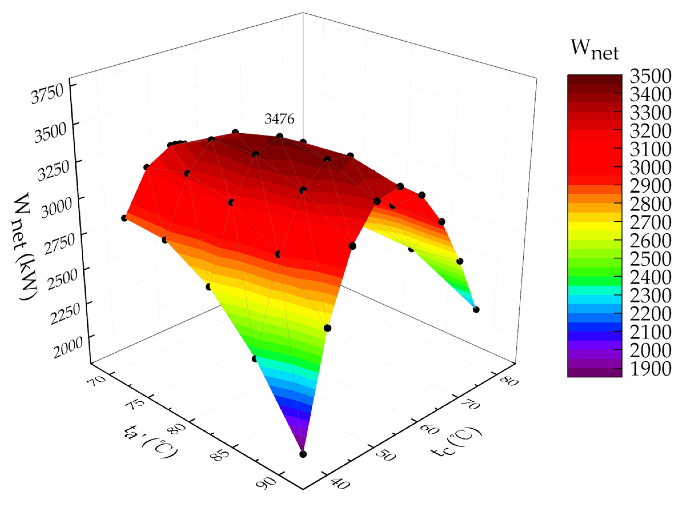
The influence of the temperature ta′ and tc on the net output power of the CD-ORC system is shown in Figure 6. On the curved surface in Figure 6, there exists a state point with the highest net output power, the coordinates of which are (80, 55, 3476). Obviously, there exists the optimal ta′ and tc that make the net output power reach the maximum value.
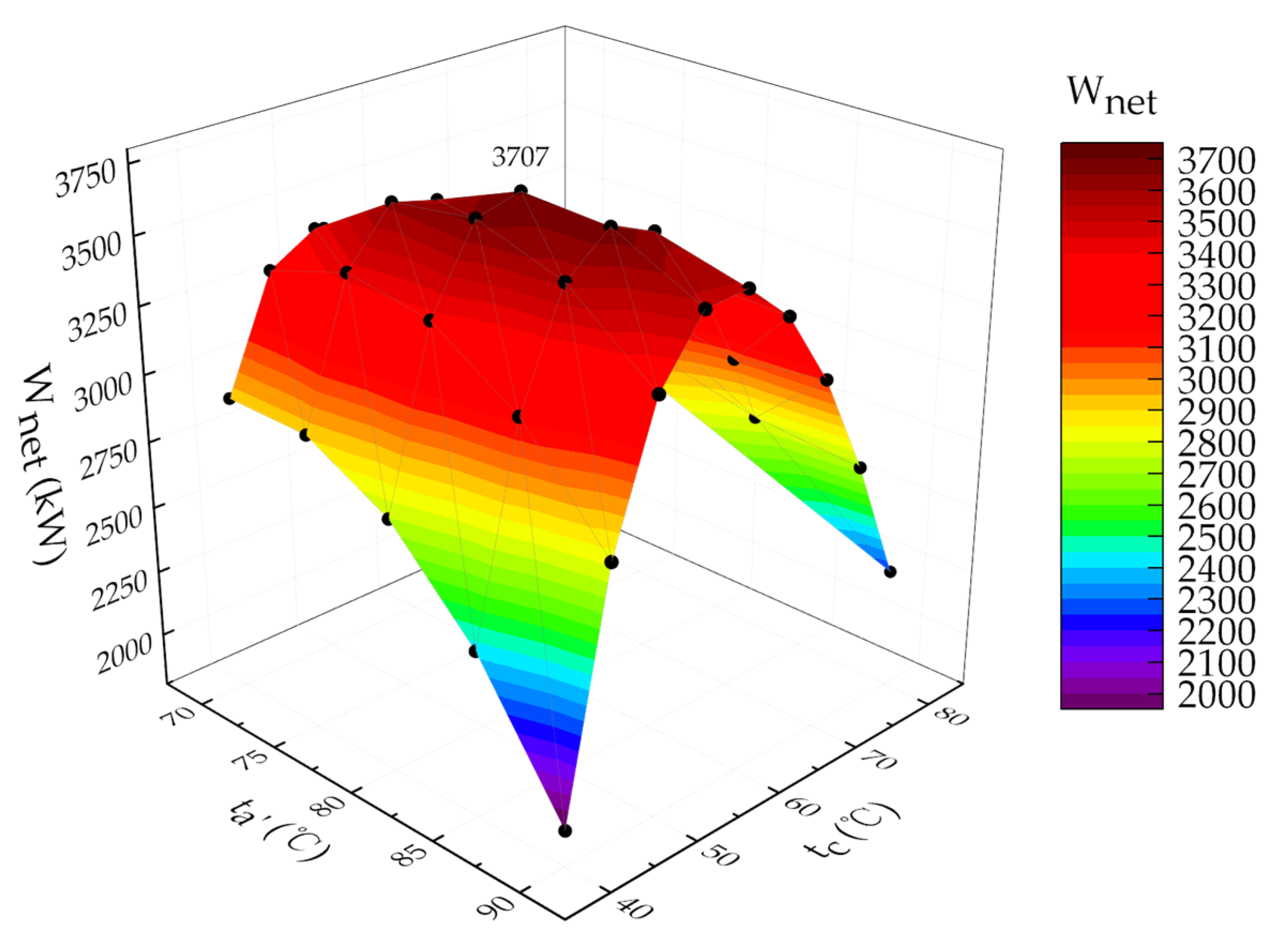
The curved surface of Figure 7 shows the effect of ta′ and tc on the net output power in the SFD-ORC system. In Figure 7, the maximum net output power is 3707 kW, corresponding to a ta′ of 80 °C, and a tc of 55 °C. The net output power is affected by two temperatures, ta′ and tc, and there exist optimal ta′ and tc values, which make the net output power reach the maximum value.

5.3. Evaluation of the Genetic Algorithm Method

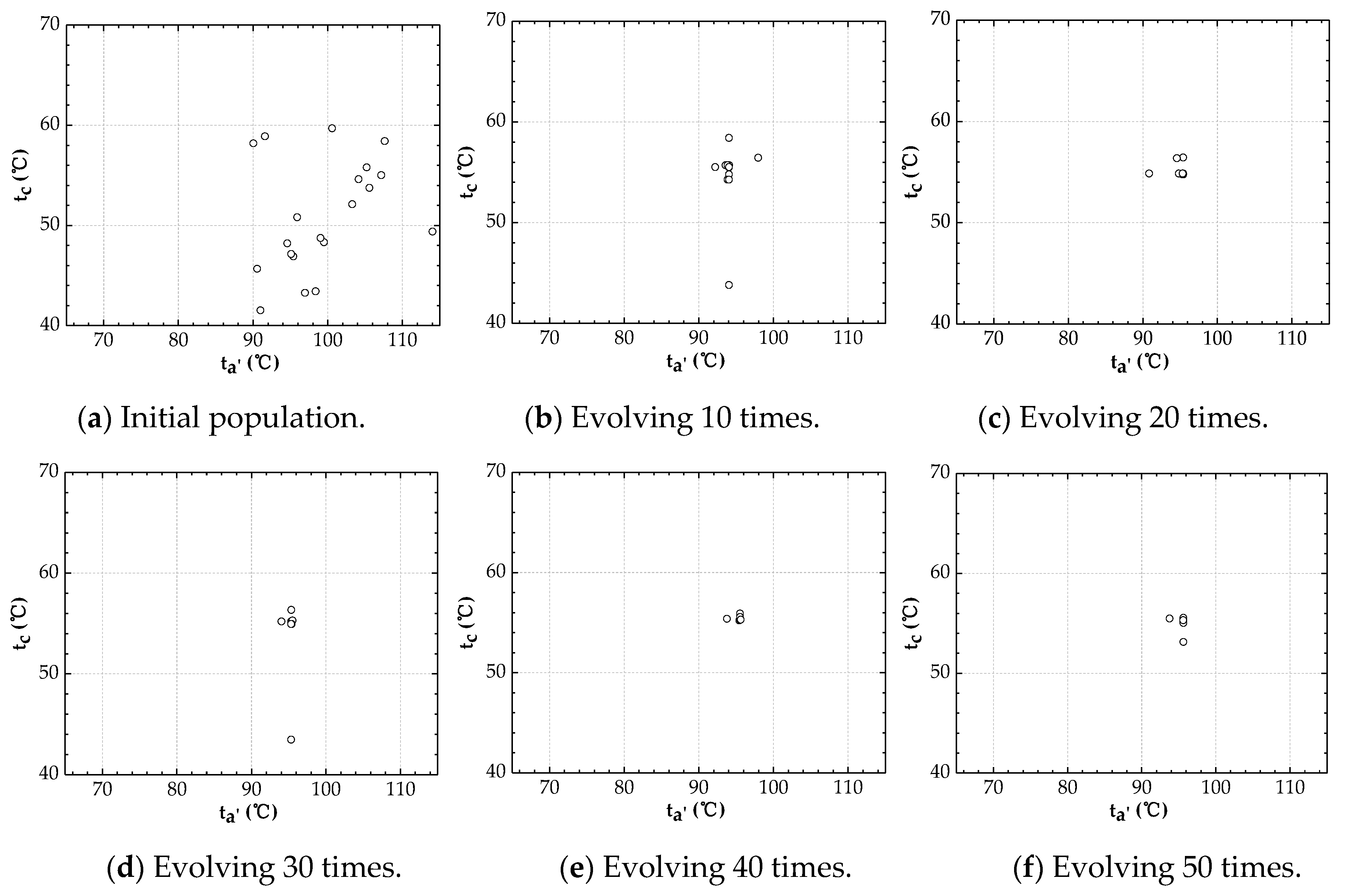
The GA was adopted to optimize the independent parameters for B-ORC, CD-ORC and SFD-ORC by taking the maximum net output power as the objective. In the evolutionary process of GA, the individuals will converge to a small area. The SFD-ORC system with a hot water temperature of 120 °C was used to evaluate the convergence of the optimal solution. Figure 8 shows the distribution of 20 individuals in 50 evolution times. As can be seen in Figure 8, the algorithm converges very quickly, and almost all individuals converge to a small area when it evolves to the 40th generation. Figure 9 shows the different individuals under 50 evolution times. From 10 individuals to 60 individuals, most individuals are able to converge to a small range, and few individuals will slightly deviate from the convergence region due to the selection, crossover and mutation of the calculation. This means that the GA method could be used to find the optimal independent parameters for ORC systems.

5.4. Optimal Parameters

The optimal hot water outlet temperature, tc, under the maximum net output power condition is shown in Figure 10. With the increase in hot water inlet temperature, ta, the optimal hot water outlet temperature increases for three ORC systems. Under the same hot water inlet temperature condition, the optimal hot water outlet temperature of B-ORC is much higher than that of CD-ORC and SFD-ORC, which indicates that less thermal energy could be utilized and converted to power in B-ORC compared with CD-ORC and SFD-ORC.
The optimal hot water temperature at the outlet of evaporator 1, ta′, under the maximum net output power condition for CD-ORC and SFD-ORC, is shown in Figure 11. It is obvious that the optimal hot water temperature at the outlet of evaporator 1, ta′, is in direct proportion to the hot water inlet temperature, ta, for two dual-pressure ORC systems. It can be found that the optimal hot water temperature at the outlet of evaporator 1 in SFD-ORC is higher than that in CD-ORC, which means SFD-ORC could make more efficient use of the high-grade thermal energy of hot water. Moreover, with the increase in hot water inlet temperature, the difference in ta′ increases. This indicates that the SFD-ORC is preferable for higher hot water inlet temperatures.
The optimal evaporation temperatures of three ORC systems are shown in Figure 12. It could be found that the evaporation temperature of B-ORC is lower than that of the high-pressure loop and higher than that of the low-pressure loop of both dual-pressure ORCs. This indicates that the high-grade heat of hot water could be effectively converted to power. Moreover, both evaporation temperatures in SFD-ORC are higher than that in CD-ORC, respectively. This means that SFD-ORC could make more efficient use of high-grade thermal energy than CD-ORC.
Figure 13 shows the results of the working fluid split ratio at the optimal operating conditions. The working fluid split ratio was defined as the ratio of the mass flow rate of working fluid in the low-pressure loop to the total mass flow rate of working fluid. In the range of ta from 90 °C to 130 °C, it can be found that the working fluid split ratio of the SFD-ORC system is more than 40% and relatively stable, while, with the increase in ta, the split ratio of the working fluid in CD-ORC system increases first and then decreases rapidly. Moreover, the working fluid split ratio of SFD-ORC is higher than that of CD-ORC and the difference increases with the increase in ta. This means that the working fluid in the low-pressure loop of SFD-ORC could absorb more heat energy than that of CD-ORC.
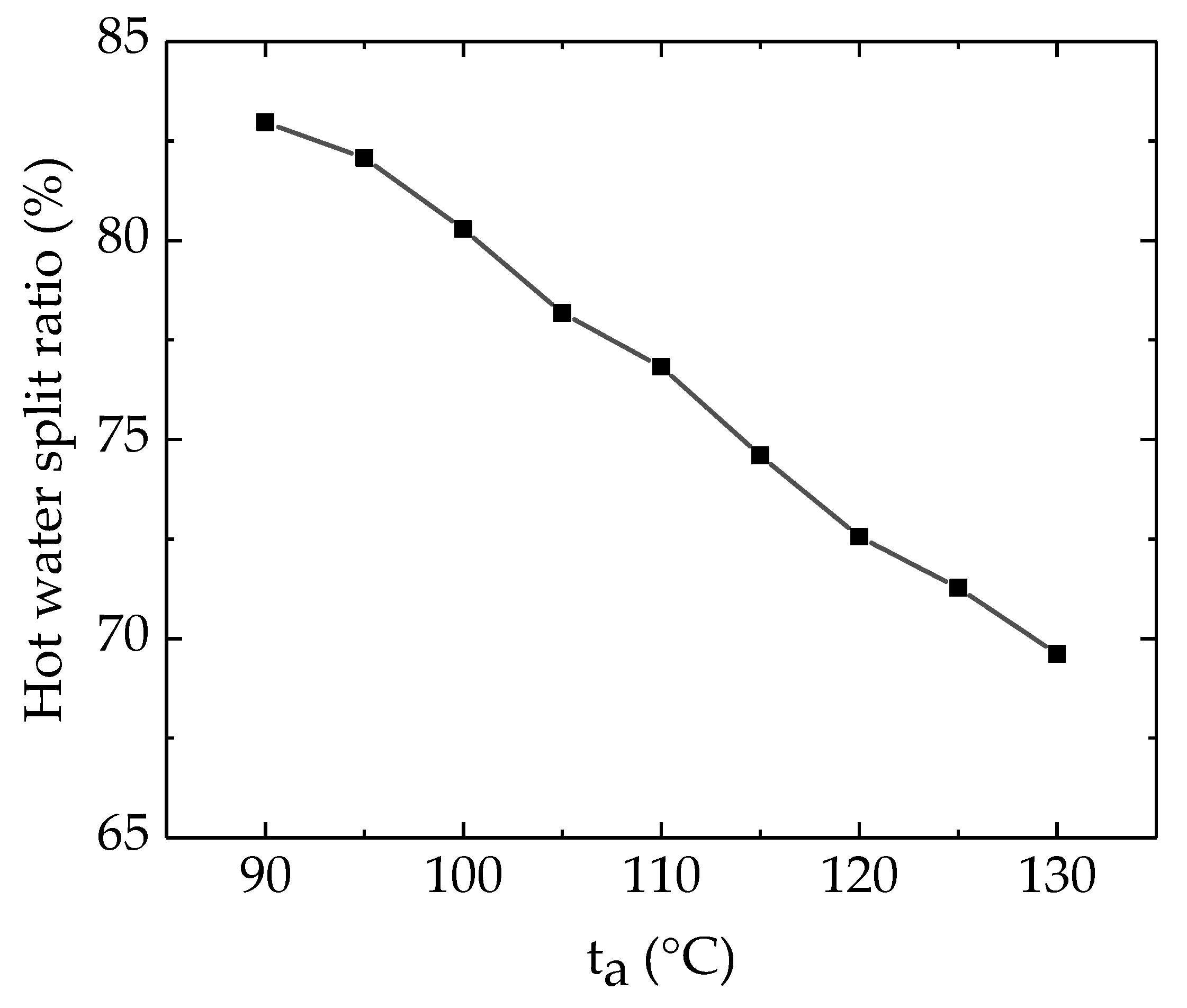
The hot water split ratio was defined as the ratio of the mass flow rate of hot water flowing into the low-pressure loop to the total mass flow rate of hot water. The variation in the hot water split ratio with the hot water inlet temperature at the optimal operating condition is shown as Figure 14. It was found that the optimal hot water split ratio decreases with the increase in the hot water inlet temperature. This indicates that, for lower temperature hot water, more mass flow rates should split into the low-pressure loop to obtain more net output power.

5.5. The Maximum Net Output Power

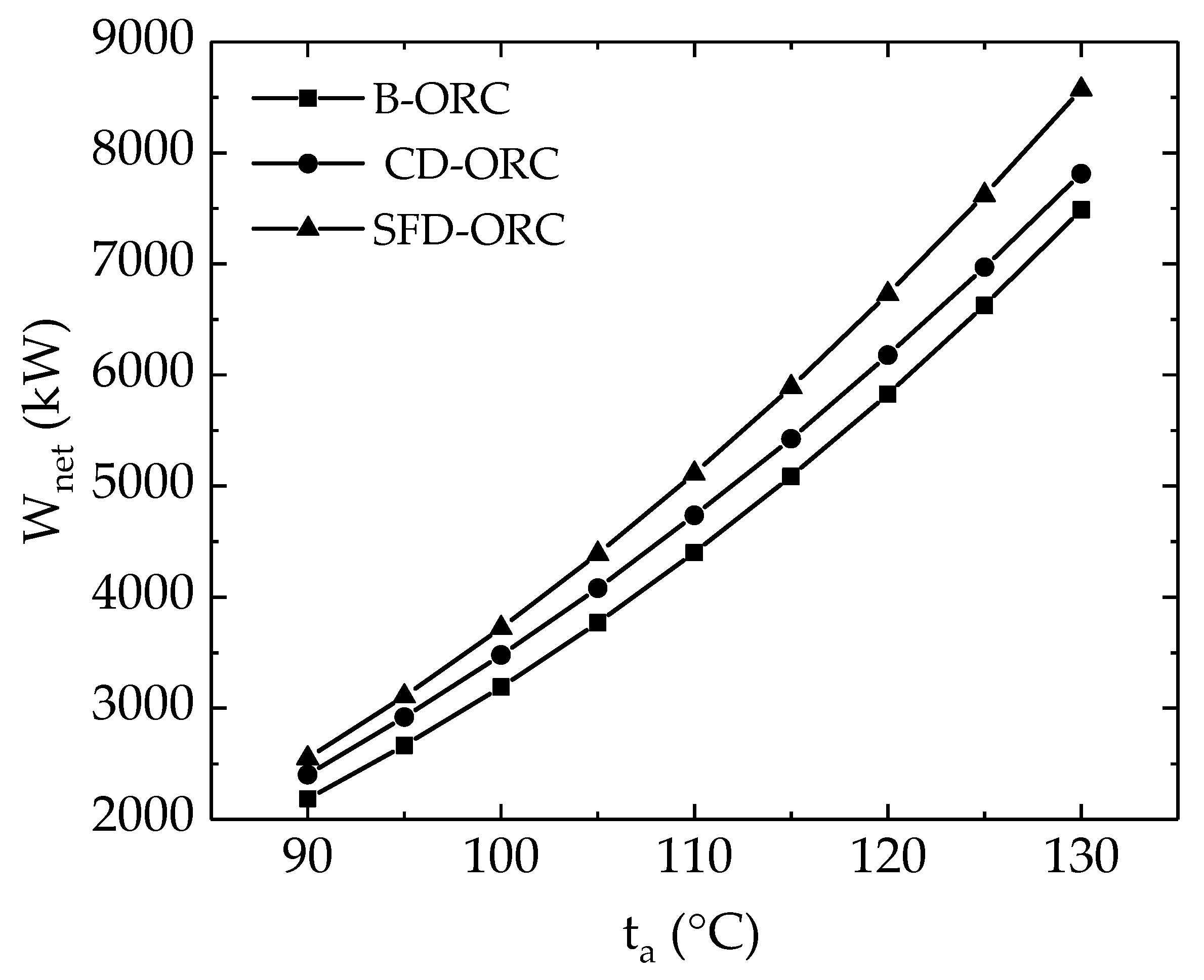
The variations in the maximum net output power with the hot water inlet temperature, ta, are shown in Figure 15. It is found that the maximum net output power, Wnet,max, is proportional to ta. SFD-ORC has the highest maximum net output power, and B-ORC has the lowest. Moreover, with the increase in ta, the advantage of SFD-ORC becomes increasingly obvious. For example, at 90 °C of ta, the maximum net output power of SFD-ORC is 149.4 kW higher than that of CD-ORC and 364.8 kW higher than that of B-ORC. When ta increases to 130 °C, the maximum net output power of SFD-ORC increases to 758 kW higher than that of the CD-ORC system and 1084.1 kW higher than that of the B-ORC system. Compared with the CD-ORC system, the net output power of SFD-ORC at 90 °C is 6.22% higher than that of CD-ORC. At 130 °C, the net output power of SFD-ORC at is 9.7% higher than that of CD-ORC. This indicates that, with the higher hot water inlet temperature, ta, the heat energy could be more efficiently converted to power by SFD-ORC.

6. Conclusions

To obtain more power for the ORC system, the hot water split-flow dual-pressure organic Rankine cycle was proposed. B-ORC, CD-ORC and SFD-ORC were compared. The GA was adopted to optimize the parameters and search for the maximum net power output of ORCs. Our conclusions are as follows:
(1)
The optimal hot water outlet temperature of B-ORC is much higher than that of CD-ORC and SFD-ORC, which indicates less thermal energy could be utilized to convert to power in B-ORC.
(2)
The optimal hot water temperature at the outlet of evaporator 1 in SFD-ORC is higher than that in CD-ORC, which means that SFD-ORC could make more efficient use of high-grade thermal energy of hot water.
(3)
SFD-ORC has the highest maximum net output power, and B-ORC has the lowest.
(4)
With the increase in hot water inlet temperature, the advantage of SFD-ORC becomes increasingly obvious. This indicates that SFD-ORC is more preferable for heat sources of a higher temperature.
(5)
SFD-ORC has great advantages in improving net output power.

Author Contributions

Methodology, Z.Y.; investigation, S.W. All authors have read and agreed to the published version of the manuscript.

Funding

This research was funded by Sichuan Science and Technology Support Program, grant number 2019YFG0327.

Conflicts of Interest

The authors declare no conflict of interest.

Nomenclature

Aarea (of heat exchanger) (m2)
cpspecific heat at constant pressure (kJ/(kg∙°C))
hspecific enthalpy (kJ/kg)
Kheat transfer coefficient (W/(m2∙°C))
mmass flow rate (kg/s)
Qheat transfer rate (kW)
ttemperature (°C)
Tthermodynamic temperature (K)
Wpower (kW)
Ppressure difference (Pa)
Tlogarithmic mean temperature difference (K)

Greek symbols

ηefficiency (%)
ρdensity (kg/m3)

Subscripts

AVGaverage
condcondenser
cond1condenser in high-pressure ORC
cond2condenser in low-pressure ORC
cwcooling water
cwpumpcooling water pump
cw1cooling water exchange heat with high-pressure ORC
cw2cooling water exchange heat with low-pressure ORC
evapevaporator
evap1high-pressure evaporator
evap2low-pressure evaporator
exexergetic
expexpander
exp1high-pressure expander
exp2low-pressure expander
hwhot water
hw′hot water split into high-pressure preheater
midbetween evaporator and preheater
netnet
pinpinch temperature difference
prepreheater
pumpworking fluid pump
pump1high-pressure fluid pump
pump2low-pressure fluid pump
sisentropic
ththermal
wfworking fluid
wf1working fluid at high evaporation pressure
wf2working fluid at low evaporation pressure
0environment
1, 1′, 1″, 2, 2′, 2″, 3, 4, 4′, 4″, 5, 5′, 5″, a, a′, a″, b, b′, b″, c state points

Abbreviations

ORCbasic organic Rankine cycle
CD-ORCconventional dual-organic Rankine cycle
GAgenetic algorithm
GATBXgenetic algorithm toolbox
SFD-ORCsplit-flow dual-organic Rankine cycle

References

  1. Jouhara, H.; Khordehgah, N.; Almahmoud, S.; Delpech, B.; Chauhan, A.; Tassou, S.A. Waste Heat Recovery Technologies and Applications. Therm. Sci. Eng. Prog. 2018, 6, 268–289. [Google Scholar] [CrossRef]
  2. Walraven, D.; Laenen, B.; D’haeseleer, W. Comparison of thermodynamic cycles for power production from low-Temperature geothermal heat sources. Energy Convers. Manag. 2013, 66, 220–233. [Google Scholar] [CrossRef] [Green Version]
  3. Imran, M.; Hajlind, F.; Asim, M.; Alvi, J.Z. Recent research trends in organic Rankine cycle technology: A bibliometric approach. Renew. Sustain. Energy Rev. 2018, 81, 552–562. [Google Scholar] [CrossRef] [Green Version]
  4. Tocci, L.; Pal, T.; Pesmazoglou, I.; Franchetti, B. Small Scale Organic Rankine Cycle (ORC): A Techno-Economic Review. Energies 2017, 10, 413. [Google Scholar] [CrossRef]
  5. Peris, B.; Navarro-Esbrí, J.; Molés, F. Bottoming organic Rankine cycle configurations to increase Internal Combustion Engines power output from cooling water waste heat recovery. Appl. Therm. Eng. 2013, 61, 364–371. [Google Scholar] [CrossRef]
  6. Walraven, D.; Laenen, B.; D’haeseleer, W. Optimum configuration of shell-and-tube heat exchangers for the use in low-Temperature organic Rankine cycles. Energy Convers. Manag. 2014, 83, 177–187. [Google Scholar] [CrossRef] [Green Version]
  7. Walraven, D.; Laenen, B.; D’Haeseleer, W. Economic system optimization of air-Cooled organic Rankine cycles powered by low-Temperature geothermal heat sources. Energy 2015, 80, 104–113. [Google Scholar] [CrossRef] [Green Version]
  8. Walraven, D.; Laenen, B.; D’haeseleer, W. Minimizing the levelized cost of electricity production from low-temperature geothermal heat sources with ORCs: Water or air cooled? Appl. Energy 2015, 142, 144–153. [Google Scholar] [CrossRef] [Green Version]
  9. Usman, M.; Imran, M.; Yang, Y.; Lee, D.H.; Park, B.-S. Thermo-Economic comparison of air-Cooled and cooling tower based Organic Rankine Cycle (ORC) with R245fa and R1233zde as candidate working fluids for different geographical climate conditions. Energy 2017, 123, 353–366. [Google Scholar] [CrossRef]
  10. Haghparast, P.; Sorin, M.V.; Richard, M.A.; Nesreddine, H. Analysis and design optimization of an ejector integrated into an organic Rankine cycle. Appl. Therm. Eng. 2019, 159, 113979. [Google Scholar] [CrossRef]
  11. Zhang, C.; Lin, J.; Tan, Y. A theoretical study on a novel combined organic Rankine cycle and ejector heat pump. Energy 2019, 176, 81–90. [Google Scholar] [CrossRef]
  12. Rathod, D.; Xu, B.; Filipi, Z.; Hoffman, M. An experimentally validated, energy focused, optimal control strategy for an Organic Rankine Cycle waste heat recovery system. Appl. Energy 2019, 256, 113991. [Google Scholar] [CrossRef]
  13. Li, L.; Ge, Y.T.; Luo, X.; Tassou, S.A. Experimental investigations into power generation with low grade waste heat and R245fa Organic Rankine Cycles (ORCs). Appl. Therm. Eng. 2017, 115, 815–824. [Google Scholar] [CrossRef]
  14. Li, J.; Hu, S.; Yang, F.; Duan, Y.; Yang, Z. Thermo-Economic performance evaluation of emerging liquid-separated condensation method in single-Pressure and dual-Pressure evaporation organic Rankine cycle systems. Appl. Energy 2019, 256. [Google Scholar] [CrossRef]
  15. Li, T.; Zhang, Z.; Lu, J.; Yang, J.; Hu, Y. Two-Stage evaporation strategy to improve system performance for organic Rankine cycle. Appl. Energy 2019, 256, 113974. [Google Scholar] [CrossRef]
  16. Li, T.; Yuan, Z.; Li, W.; Yang, J.; Zhu, J. Strengthening mechanisms of two-stage evaporation strategy on system performance for organic Rankine cycle. Energy 2016, 101, 532–540. [Google Scholar] [CrossRef]
  17. Li, T.; Meng, N.; Liu, J.; Zhu, J.; Kong, X. Thermodynamic and economic evaluation of the organic Rankine cycle (ORC) and two-Stage series organic Rankine cycle (TSORC) for flue gas heat recovery. Energy Convers. Manag. 2019, 183, 816–829. [Google Scholar] [CrossRef]
  18. Wang, Q.; Wang, J.; Li, T.; Meng, N. Techno-Economic performance of two-Stage series evaporation organic Rankine cycle with dual-Level heat sources. Appl. Therm. Eng. 2020, 171, 115078. [Google Scholar] [CrossRef]
  19. Tang, Y. Single Stage and Cascaded Organic Rankine Cycles with Screw Expanders Used for Hot Fluids in Oil Refineries and Chemical Plants. In Proceedings of the International Refrigeration and Air Conditioning Conference, West Lafayette, IN, USA, 11–14 July 2016. [Google Scholar]
  20. Yari, M. Exergetic analysis of various types of geothermal power plants. Renew. Energy 2010, 35, 112–121. [Google Scholar] [CrossRef]
  21. Rashwan, S.S.; Dincer, I.; Mohany, A. Analysis and assessment of cascaded closed loop type organic Rankine cycle. Energy Convers. Manag. 2019, 184, 416–426. [Google Scholar] [CrossRef]
  22. Li, J.; Ge, Z.; Duan, Y.; Yang, Z.; Liu, Q. Parametric optimization and thermodynamic performance comparison of single-Pressure and dual-Pressure evaporation organic Rankine cycles. Appl. Energy 2018, 217, 409–421. [Google Scholar] [CrossRef]
  23. Cayer, E.; Galanis, N.; Nesreddine, H. Parametric study and optimization of a transcritical power cycle using a low temperature source. Appl. Energy 2010, 87, 1349–1357. [Google Scholar] [CrossRef]
  24. Wang, M.; Zhang, J.; Zhao, S.; Liu, Q.; Zhao, Y.; Wu, H. Performance investigation of transcritical and dual-pressure Organic Rankine Cycles from the aspect of thermal match. Energy Convers. Manag. 2019, 197. [Google Scholar] [CrossRef]
  25. Yu, X.; Li, Z.; Lu, Y.; Huang, R.; Roskilly, A. Investigation of an Innovative Cascade Cycle Combining a Trilateral Cycle and an Organic Rankine Cycle (TLC-ORC) for Industry or Transport Application. Energies 2018, 11, 3032. [Google Scholar] [CrossRef] [Green Version]
  26. Xi, H.; Li, M.-J.; Xu, C.; He, Y.-L. Parametric optimization of regenerative organic Rankine cycle (ORC) for low grade waste heat recovery using genetic algorithm. Energy 2013, 58, 473–482. [Google Scholar] [CrossRef]
  27. Palagi, L.; Sciubba, E.; Tocci, L. A neural network approach to the combined multi-Objective optimization of the thermodynamic cycle and the radial inflow turbine for Organic Rankine cycle applications. Appl. Energy 2019, 237, 210–226. [Google Scholar] [CrossRef]
  28. Kim, J.-S.; Kim, D.-Y.; Kim, Y.-T. Experiment on radial inflow turbines and performance prediction using deep neural network for the organic Rankine cycle. Appl. Therm. Eng. 2019, 149, 633–643. [Google Scholar] [CrossRef]
  29. Zhao, R.; Zhang, H.; Song, S.; Yang, F.; Hou, X.; Yang, Y. Global optimization of the diesel engine–organic Rankine cycle (ORC) combined system based on particle swarm optimizer (PSO). Energy Convers. Manag. 2018, 174, 248–259. [Google Scholar] [CrossRef]
  30. Valencia Ochoa, G.; Acevedo Peñaloza, C.; Duarte Forero, J. Thermoeconomic Optimization with PSO Algorithm of Waste Heat Recovery Systems Based on Organic Rankine Cycle System for a Natural Gas Engine. Energies 2019, 12, 4165. [Google Scholar] [CrossRef] [Green Version]
  31. Özkaraca, O.; Keçebaş, P.; Demircan, C.; Keçebaş, A. Thermodynamic Optimization of a Geothermal-Based Organic Rankine Cycle System Using an Artificial Bee Colony Algorithm. Energies 2017, 10, 1691. [Google Scholar] [CrossRef] [Green Version]
  32. Dong, S.; Zhang, Y.; He, Z.; Deng, N.; Yu, X.; Yao, S. Investigation of Support Vector Machine and Back Propagation Artificial Neural Network for performance prediction of the organic Rankine cycle system. Energy 2018, 144, 851–864. [Google Scholar] [CrossRef]
  33. MathWorks, Matlab. Available online: https://www.mathworks.cn/products/matlab.html (accessed on 21 March 2020).
  34. Nist, Refprop. Available online: https://www.nist.gov/srd/refprop (accessed on 15 January 2020).
  35. Lei, Y.; Zhang, S.; Li, X.; Zhou, C. Basic genetic algorithm and improvement. In Genetic Algorithm Toolbox; Long, H., Qi, W., Eds.; Xidian University Press: Shanxi, China, 2005; pp. 11–17. [Google Scholar]
  36. He, C.; Liu, C.; Gao, H.; Xie, H.; Li, Y.; Wu, S.; Xu, J. The optimal evaporation temperature and working fluids for subcritical organic Rankine cycle. Energy 2012, 38, 136–143. [Google Scholar] [CrossRef]
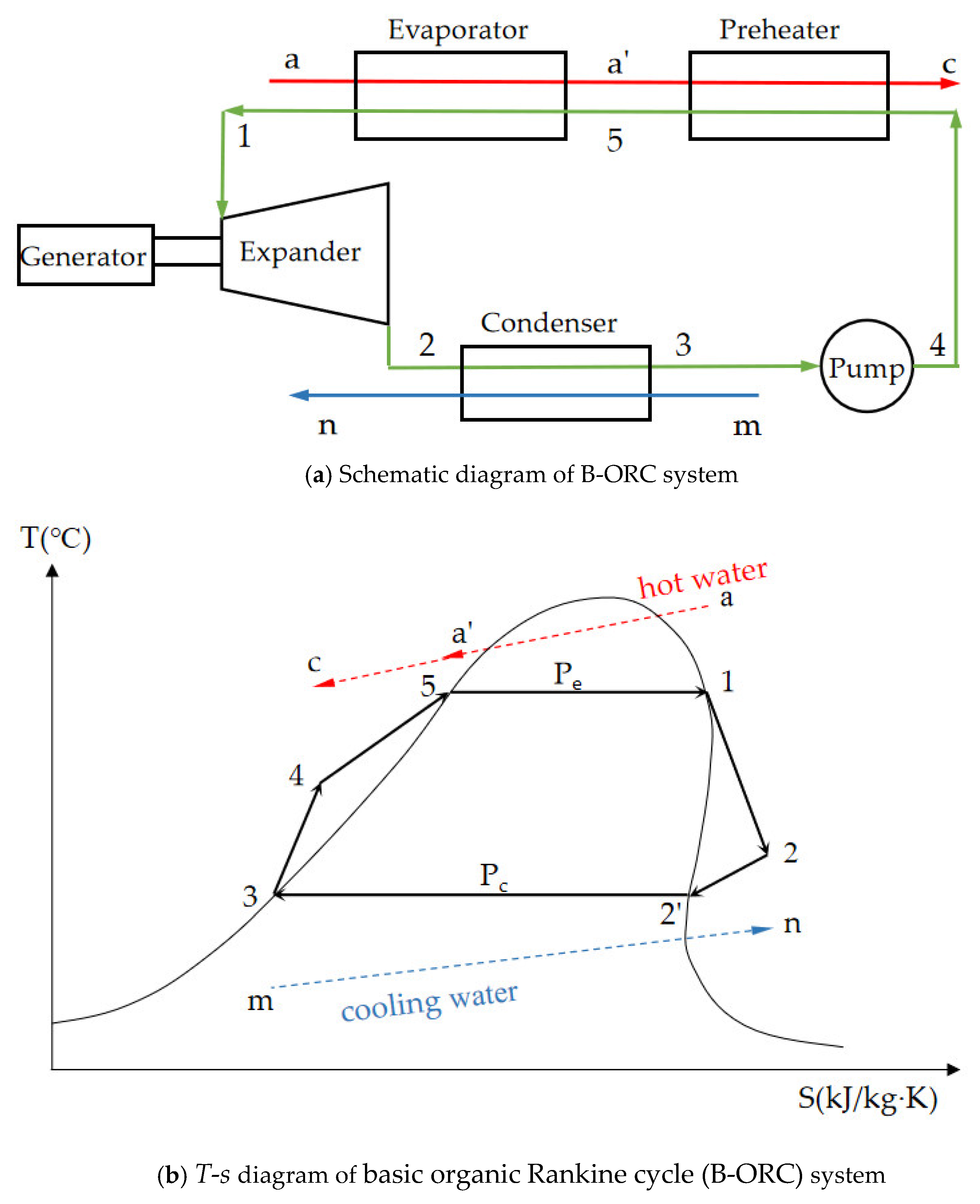
Figure 1. Scheme and the theoretical T-s diagram of B-ORC system.
Energies 13 03345 g001
Figure 2. Scheme and the theoretical T-s diagram of CD-ORC system.
Energies 13 03345 g002
Figure 3. Scheme and the theoretical T-s diagram of SFD-ORC system.
Energies 13 03345 g003
Figure 4. Flow chart of genetic algorithm method scheme.
Energies 13 03345 g004
Figure 5. Influence of tc on net output power of B-ORC.
Energies 13 03345 g005
Figure 6. Influence of ta′ and tc on net output power of CD-ORC.
Energies 13 03345 g006
Figure 7. Influence of ta′ and tc on net output power of SFD-ORC.
Energies 13 03345 g007
Figure 8. The distribution of 20 individuals in 50 evolution times.
Energies 13 03345 g008
Figure 9. The distribution of different individuals under 50 evolution times.
Energies 13 03345 g009
Figure 10. The optimal hot water outlet temperature.
Energies 13 03345 g010
Figure 11. The optimal hot water temperature at the outlet of evaporator 1.
Energies 13 03345 g011
Figure 12. The results of the evaporation temperature at the optimal operating conditions.
Energies 13 03345 g012
Figure 13. The mass flow rate of working fluid at the optimal operating conditions.
Energies 13 03345 g013
Figure 14. The hot water split ratio in SFD-ORC at the optimal operating conditions.
Energies 13 03345 g014
Figure 15. The variation in the net output power with ta.
Energies 13 03345 g015
Table 1. Simulation parameters and boundary conditions used in this paper.
ParametersValue
Ambient temperature (°C)25
Ambient pressure (kPa)101.3
Condensation temperature (°C)30
Cooling water inlet temperature (°C)25
Cooling water outlet temperature (°C)30
Hot water mass flow rate (kg/s)324.2
Hot water inlet temperature (°C)90–130
Pinch temperature difference (°C)3
Working fluid pump isentropic efficiency70%
Working fluid pump equipment efficiency75%
Cooling water pump isentropic efficiency80%
Cooling water pump equipment efficiency90%
Expander isentropic efficiency85%
Expender equipment efficiency95%
Table 2. Configurations of genetic algorithms in this paper.
Population size20
Maximum number of generations50
Precision of variables20
Objective functionWnet
Selection methodstochastic universal sampling (SUS)
Crossover probability0.7
Mutation probability0.01