1. Introduction
Nuclear fuel claddings are crucial core materials in nuclear power plants. They effectively transfer the heat generated by the fission reaction to the coolant, while preventing the fuel and fission products from leaking into the coolant. Therefore, selecting cladding materials with high corrosion resistance, suitable mechanical properties, and the ability to withstand high pressures, temperatures, and irradiation is vital. Zirconium alloys have shown high potential as cladding materials, owing to their low neutron absorption rate, high corrosion resistance, and stable mechanical properties under the operating conditions of the reactor [
1,
2,
3,
4]. However, zirconium alloys were found to lack sufficient physical and chemical stability in the Fukushima nuclear power plant accident, highlighting the necessity for research on the development of accident-tolerant fuel (ATF) claddings with improved physicochemical stability. Several alternative ATF claddings have been developed in and outside of Korea, including the M5 physical vapor deposition (PVD)-coated cladding by AREVA [
5], the Fe-Cr-Al alloy by ORNL [
6], the SiC/SiCf composite by MIT [
7], and the Cr laser coating by KAERI [
8,
9]. However, the ATF cladding fabrication techniques described above have the following disadvantages: it is difficult to achieve uniform surface modifications, such as coatings, on long fuel rods, and issues such as peeling can occur due to thermal shock [
10]; FeCrAl alloys experience neutron absorption and tritium emission problems [
11]; SiC/SiC
f composite claddings consist of ceramics and are therefore exceedingly unstable in terms of fatigue behavior; and, finally, the abovementioned claddings are difficult to mass-produce, and also incur high production costs [
12,
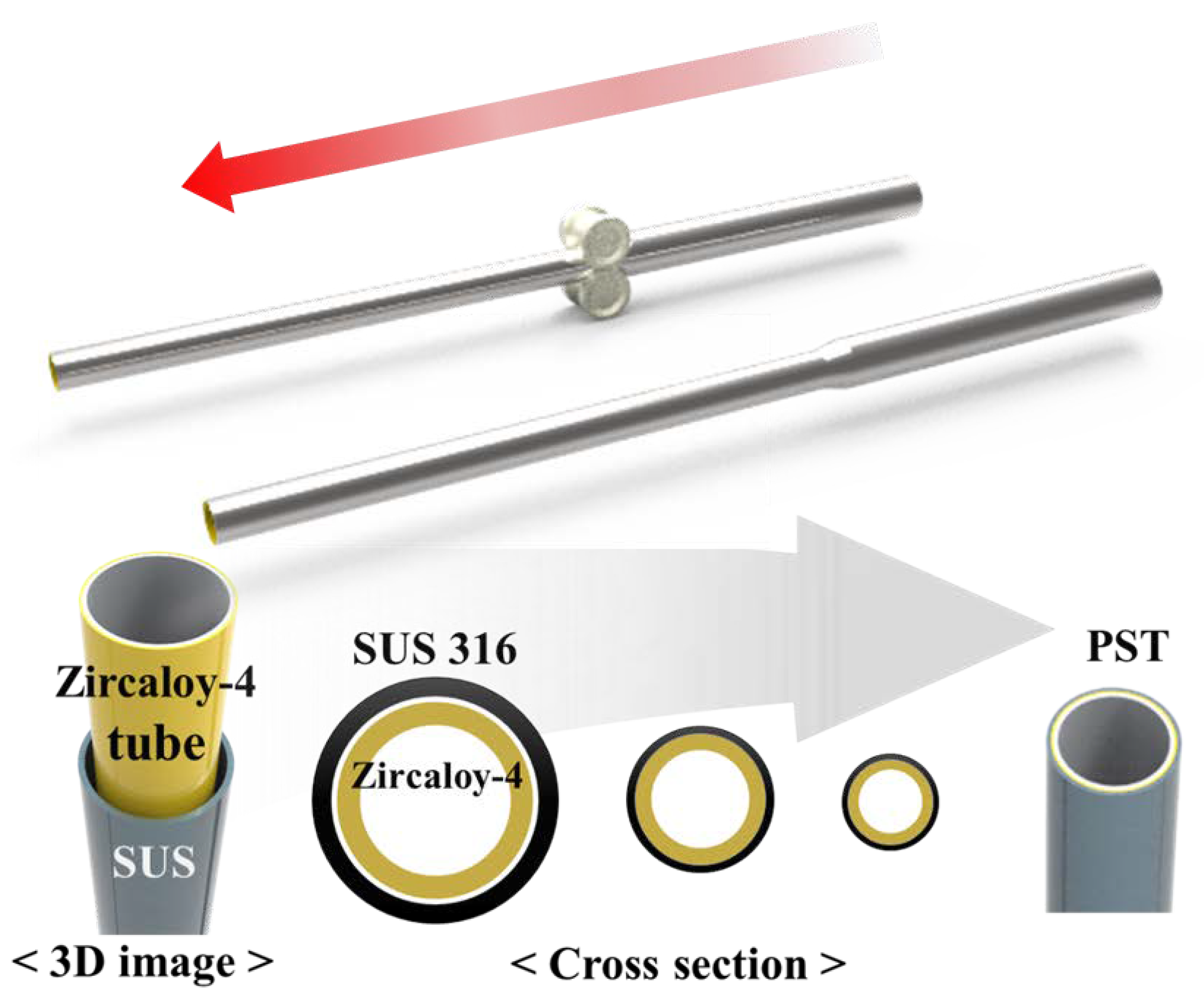
13]. To overcome these shortcomings, we propose swaging as an alternative method for the production of ATF claddings. Swaging is a simple process and can be carried out at room temperature. In general, the term “swaging” refers to the process of creating a tube with an outer diameter of a desired size by applying a physical force toward the center of a tube with a larger outer diameter. In this study, swaging indicates the process whereby a tube is inserted into another tube that has an inner diameter greater than the outer diameter of the inserted tube; subsequently, these tubes are joined by applying compressive and tensile stresses toward the center and along the lengths to form a pseudo-single tube (PST) without gaps. If a metal or alloy material with physicochemical properties suitable for nuclear power plant operations is produced in the form of a tube into which Zircaloy-4 can be inserted, there is a possibility that a PST of a length of several meters (more than 1 m) can be easily manufactured using swaging. This process requires a 4 t/cm
2 load rolling press, and the finished PST has an increased length and a reduced outer diameter compared with the starting tube. The entire swaging process is performed at room temperature; hence, there are no heat-induced formations of microstructures or phase deformations during the process. A heat treatment test confirmed that the interface of the PST remained thermally stable at high temperatures. Furthermore, with swaging, surface modification is possible without length constraints and the results of heat treatment suggest that the PST is suitable for use as an ATF cladding [
14,
15,
16]. The biggest advantage of swaging compared to the coating method is that uniform cladding can be manufactured in a short time at low cost. This advantage can be increased as the size of cladding increases, which leads to the expectation of mass productivity. The coating method may be more advantageous than swaging to set the optimum point of the cladding thickness but there may be many shortcomings in terms of practical use [
17]. When cladding is formed over the entire area of a metric cylindrical tube, it is necessary to verify whether the optimal thickness can be formed uniformly. This is important because it is directly related to the safety of nuclear energy. The produced PSTs can also be applied in other industries in the form of metal tubes, which can be manufactured with the desired physical and chemical properties, depending on the choice of materials and the thickness of the outer and inner tubes.
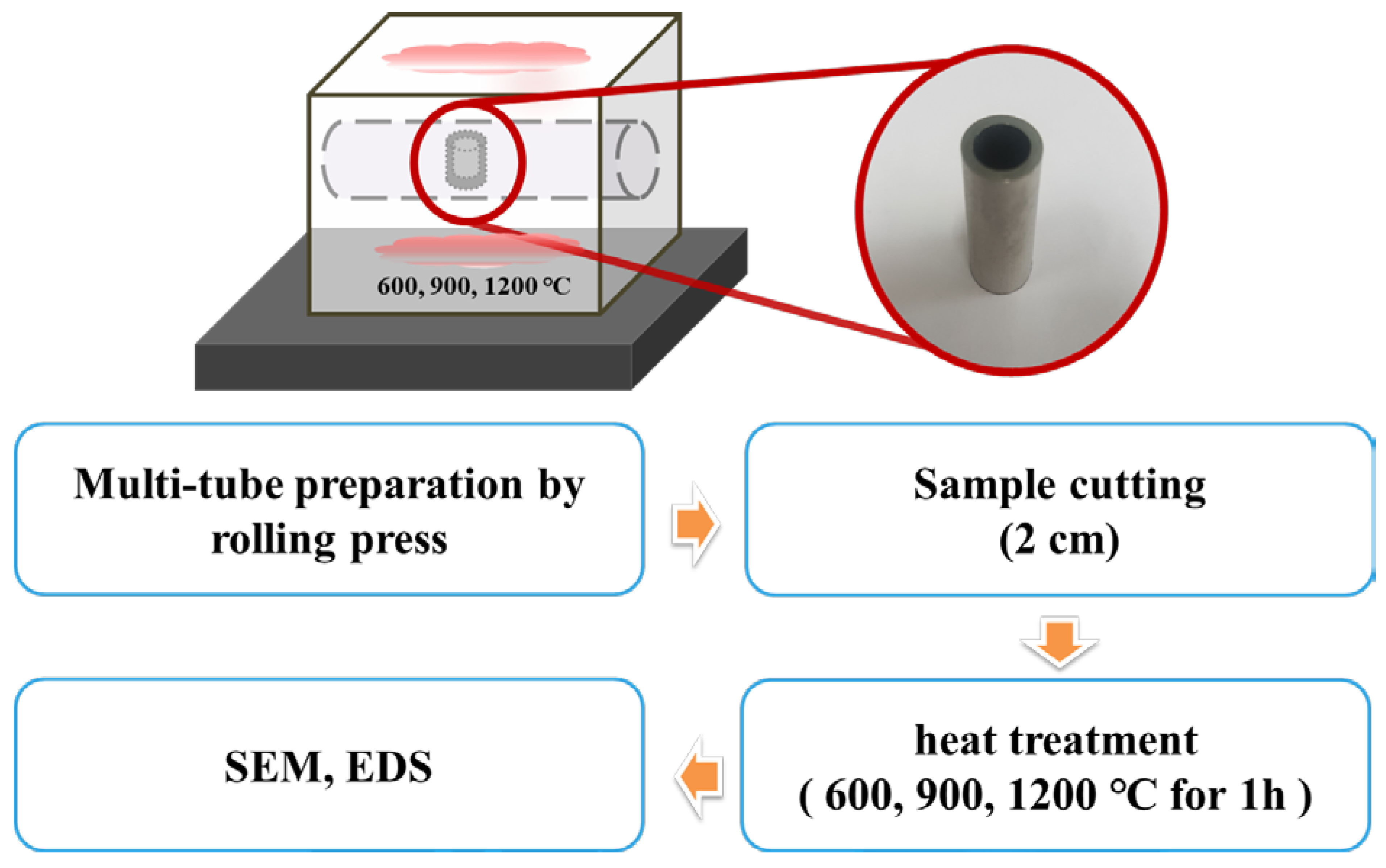
Although in this study, a sample with an ATF geometry (cladding length and thickness) that is directly applicable to nuclear operations has not been used, a 90 cm-long PST was constructed of stainless use steel (SUS) 316 (outside) and Zircaloy-4 (inside) and its high-temperature stability was confirmed. Based on this, we suggest that swaging can be an alternative process for the fabrication of ATF claddings. For this purpose, the interface between the two metals of a PST tube was analyzed before and after high-temperature heat treatment by optical microscopy (OM) and scanning electron microscopy (SEM). Furthermore, Zircaloy-4 cladding and Zircaloy-4 with SUS 316 on the surface, i.e., PST, were exposed to high temperatures for the same durations and their physicochemical stabilities were compared. The core of this study is to suggest a simple and practical process method that can compensate for the disadvantages of the existing coating method. The most frequently mentioned cladding materials are Cr or Cr-based alloys and studies to optimize them are still incomplete. For the swaging process, a cladding tube manufactured in the form of a pipe is required and the difficulty of its manufacture serves as a barrier to the progress of this study [
18]. In this situation, we have conducted prior studies on the applicability of the swaging process for ATF cladding by focusing on the process method using SUS 316, which has excellent oxidation resistance, heat resistance, and workability and is readily available. Although SUS 316 is not the optimal material for ATF cladding, we think it is persuasive to use it to confirm the possibility of the swaging process.
3. Results and Discussion
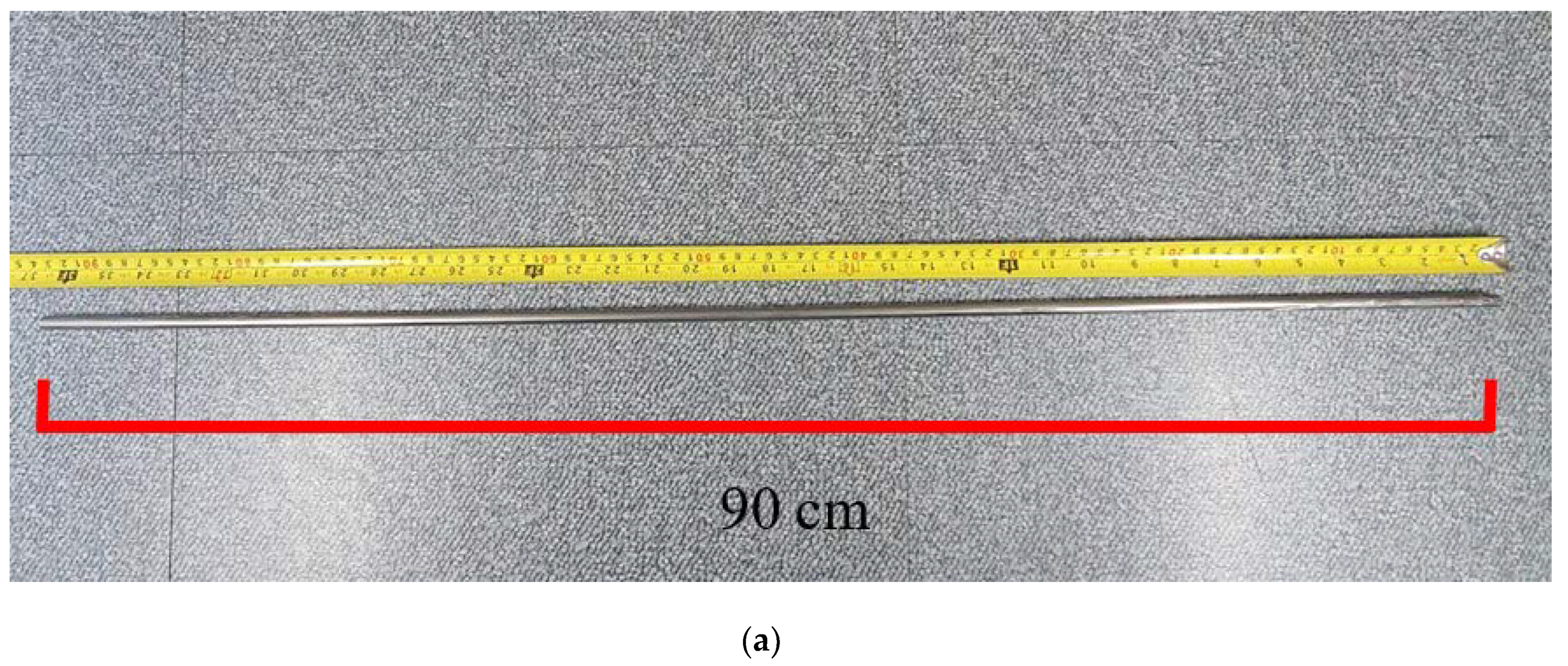
Figure 4a shows the fabricated 90 cm-long PST and
Figure 4b shows its cross-section before and after swaging. From
Figure 4b it can be seen that some KNO
3 filler remained inside the tube with the smaller internal diameter after swaging, which could be easily removed with water.
Figure 5 shows the OM image of three points on the interface of the PST. This image confirms that there were no gaps or voids in all three points of the interface between the two tubes, which was brought about by applying stress radially inward and lengthwise. Furthermore, the bonding interface between the two tubes was determined to be the same along the entire circumference. The uniformity of the interface of the PST was further confirmed by SEM images of the metal interface, as shown in
Figure 6. It is imperative to note that gaps in the interface can degrade the mechanical and chemical properties of the tube. An interface without three-dimensional defects, such as gaps or voids, does not undergo oxidation reactions; therefore, it does not experience mechanical and chemical decomposition, even in high temperatures or corrosive environments [
19]. As shown in
Figure 6, the PST fabricated by swaging exhibits an exceedingly dense interface without three-dimensional defects.
A peculiarity was that the tube thickness increased by approximately 5% from 3.35 to 3.52 mm after swaging, which can be explained as follows: during swaging, powder fillers were subjected to compressive stress in the direction of the center of the tube. Owing to plastic deformation, the inner diameter of the tube did not return to its original state, even after removal of the compressive stress [
20]. During the initial stages of swaging, the tube length remained unchanged, thus increasing the tube thickness.
Once the filling powder entered a high-density state in which it could not be compressed further during swaging, the metal tube was also no longer compressed under external compressive stress. After this step, the tube started becoming longer and thinner due to the tensile stress applied to the tube. When using the swaging process, the magnitudes of the compressive stress acting perpendicular to the axial longitudinal direction and the tensile stress acting in the longitudinal direction were the most important variables for determining the length and thickness of the final PST. It is crucial to design a PST such that the initial sum of the thickness of each tube is as close as possible to the thickness of the single Zircaloy-4 tube currently in use. In particular, after completion of the process, the outer tube should ideally be suited to possess a thickness that modifies the chemical properties of the surface with little effect on the mechanical properties of the Zircaloy-4 and the degree of neutron absorption. Therefore, it is preferable to start the process with an outer tube as thin as possible. However, as mentioned above, in this study, the swaging process was carried out using a commercially available thick SUS 316 tube for the purpose of proving that Zircaloy-4 and dissimilar metals can be produced in the PST form using the described tube process. We are currently investigating the relationship between compressive stress and tube length and thickness.
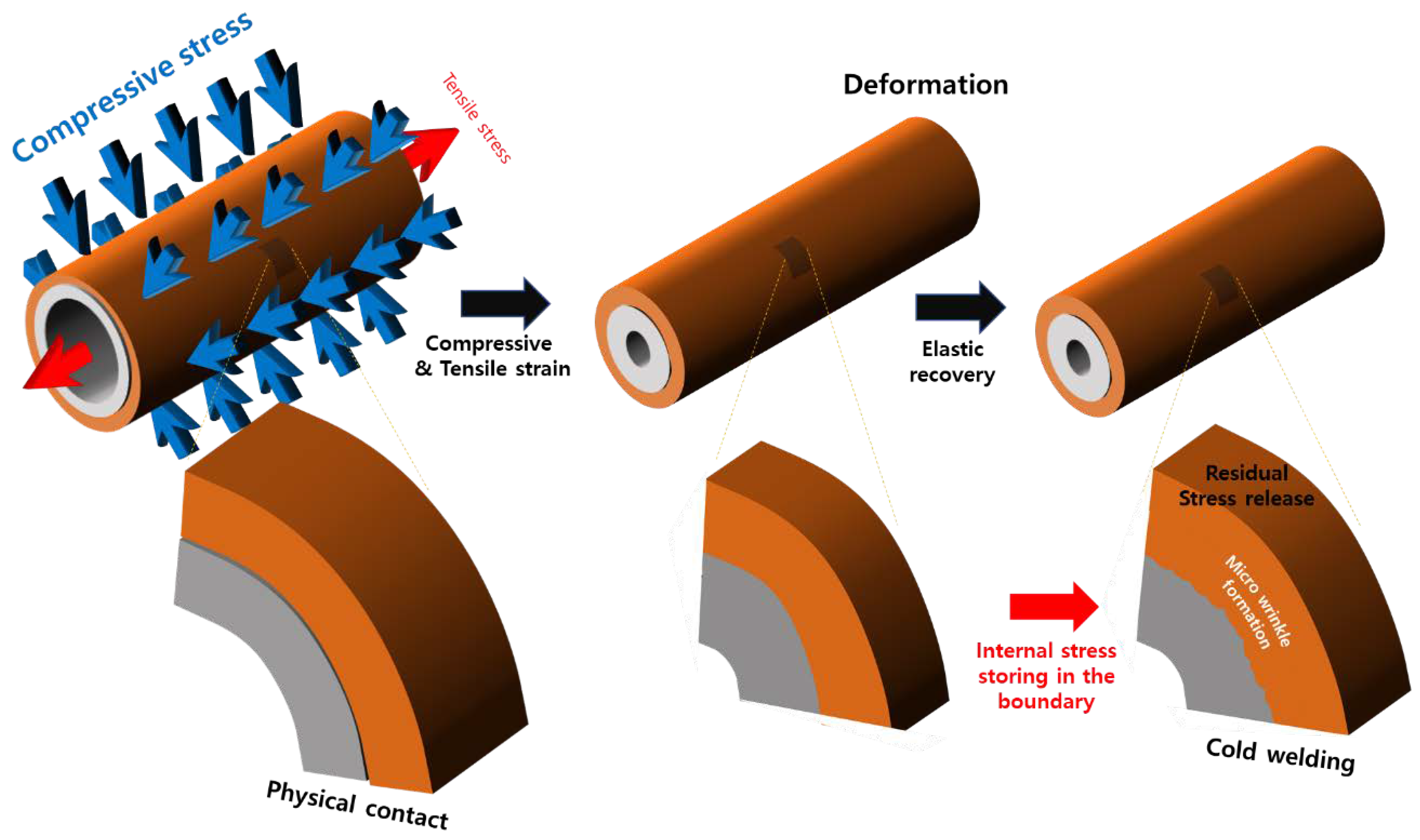
At room temperature, the physical pressure applied toward the center of the tube and in the longitudinal direction of the two tubes leads to the formation of an interface with a strong bonding force. This can be explained by the mechanism, as illustrated in
Figure 2. During swaging, the tube was subjected to compressive and tensile stresses in the axial and longitudinal directions. However, the tensile stress acting in the axial direction of the tube was not generated by the tube being pulled from the outside in the swaging equipment. This stress is thought to have been generated by the KNO
3 filler pressing toward the center. Tensile stress occurred in the longitudinal direction of the tube, as the inner diameter of the tube decreased, when a force of 4 t/cm
2 was applied to the center of the tube. This can be understood from the fact that the tube length increased after swaging, even if no tensile stress was applied. The most frequently mentioned cladding materials are Cr or Cr-based alloys and studies to optimize them are still incomplete. Because of this, it is not yet possible to measure or calculate the exact magnitude of the tensile stress generated in the longitudinal direction by the reduction of the inner diameter of the tube with the equipment used in this study. Clearly, however, the most important variable in the shaft process is the control of the compressive stress applied in the direction of the center of the shaft. We are designing and manufacturing new tube equipment that can accurately measure and control the magnitude of the tensile stresses created in the longitudinal direction induced by compressive stresses, along with the values of the compressive stresses.
Differences in physical properties, such as in the moduli of elasticity, shear moduli, and tensile strengths of the two metals after the tube process, result in different shrinkage behavior after stretching.
Table 1 shows various physical properties of Zircaloy-4 and SUS 316. The total strain generated by swaging consists of a combination of elastic strain and plastic strain. An elastic deformation results in a return to the original state when the applied stress is removed; however, some permanent deformation, that is, plastic deformation, remained as the yield strength was exceeded. Finally, this plastic deformation resulted in a PST which is longer than the initial tube and has a smaller inner diameter than the initial tube [
21]. As can be inferred from
Table 1, Zircaloy-4 and SUS 316 tubes have different yield strengths, which can result in different final shrinkages. The first tube was 90 cm in length but post the tube process, the lengths of the Zircaloy-4 and SUS 316 tubes increased to 97.5 and 95.4 cm, respectively.
Table 2 shows the sizes of the tubes before and after swaging. It can be seen that the outer and inner diameters decrease after the shaft.
Thus, SUS 316, which experienced a relatively small plastic deformation, shrank more than Zircaloy-4. It is likely that the residual stress generated at the interface between the metal surface with a low plastic strain (high shrinkage) and the metal surface with a high plastic strain (low shrinkage) caused the two metal surfaces to adhere strongly to each other. In other words, SUS 316, which experienced a high degree of shrinkage, generated compressive stress on the surface of Zircaloy-4, which experienced only a low degree of shrinkage. Meanwhile, tensile stress was generated on the surface of SUS 316. The mechanism of the strong physical adhesion of the tubes, owing to the different residual stresses generated by the shaft tube process, is shown in
Figure 7. This mechanism leads to a stable interfacial structure between the metal surfaces, as shown in the cross-sectional SEM image of the tube after swaging (
Figure 6). Upon close observation of the interface between the two metals in
Figure 6, it is evident that there is a small corrugated interfacial structure. In other words, the compressive stress generated on the surface of Zircaloy-4 due to the different shrinkage amounts of the two metals caused the Zircaloy-4 surface to shrink again, thereby forming wrinkles on the surface. This corrugated structure may have resulted in the grasping of the surface of SUS 316, which in turn led to the bonding of the two different metals after room temperature condensation. Such strong adhesive interface behavior was well demonstrated with quenching heat treatment experiments after high-temperature exposure, as shown below.
To evaluate the thermal stability of the PST fabricated using the room-temperature condensation process, an experiment was performed where the PST underwent rapid cooling after exposure to high temperature under ambient conditions.
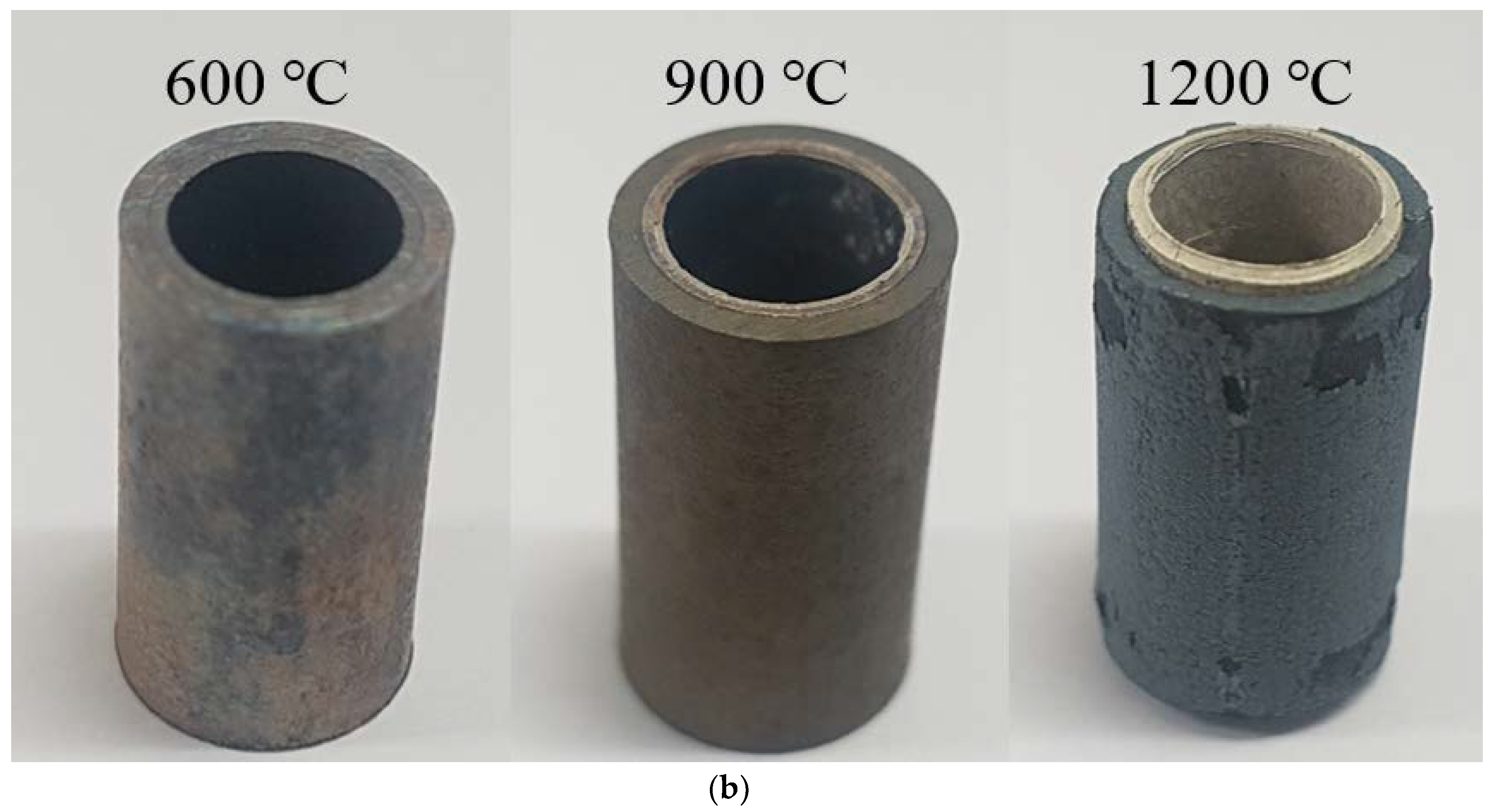
Figure 8 shows an image of a Zircaloy-4 tube and a PST quenched to room temperature after being maintained at temperatures of 600, 900, or 1200 °C for 1 h. The color of the bare Zircaloy-4 cladding changed due to oxidation, even at 600 °C. Under 1200 °C, the PST disintegrated not only due to severe oxidation phenomenon but also experienced external surface peeling [
22].
Noticeably, the structural breakdown of the Zircaloy-4 tube after being exposed to high temperatures is exceedingly similar to the high-temperature disintegration of natural limestone [
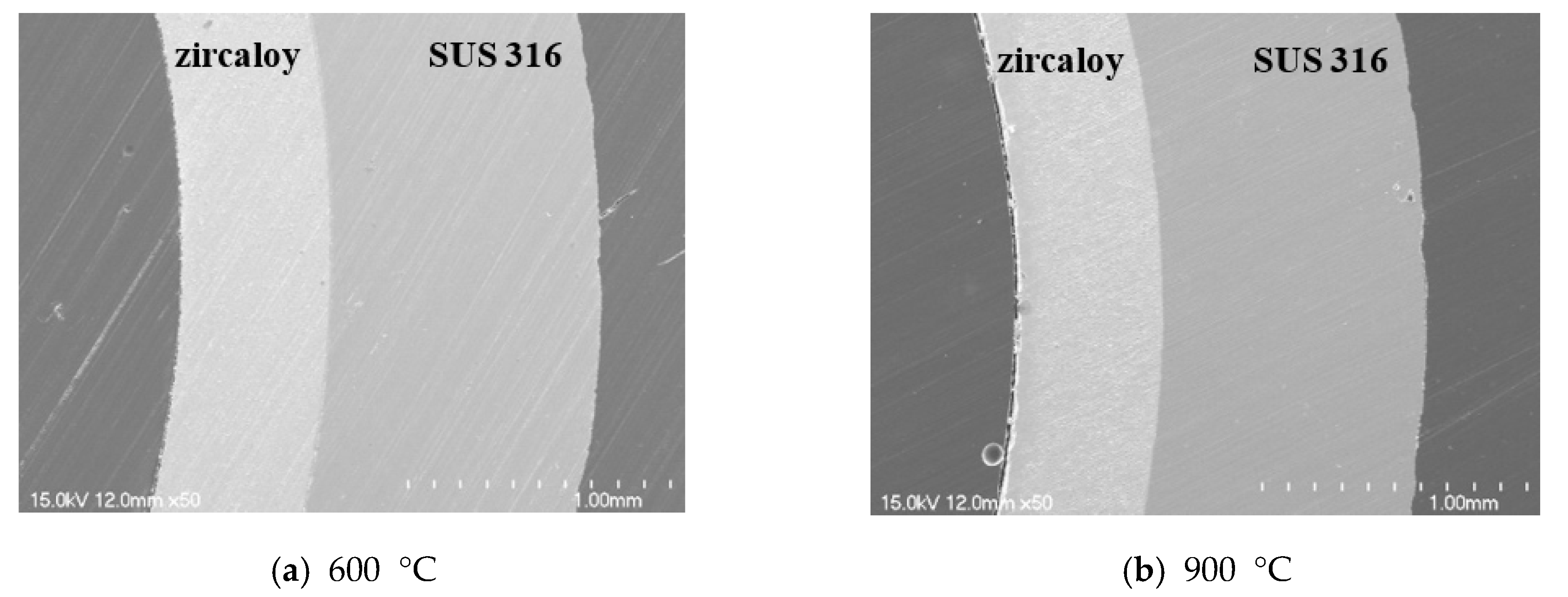
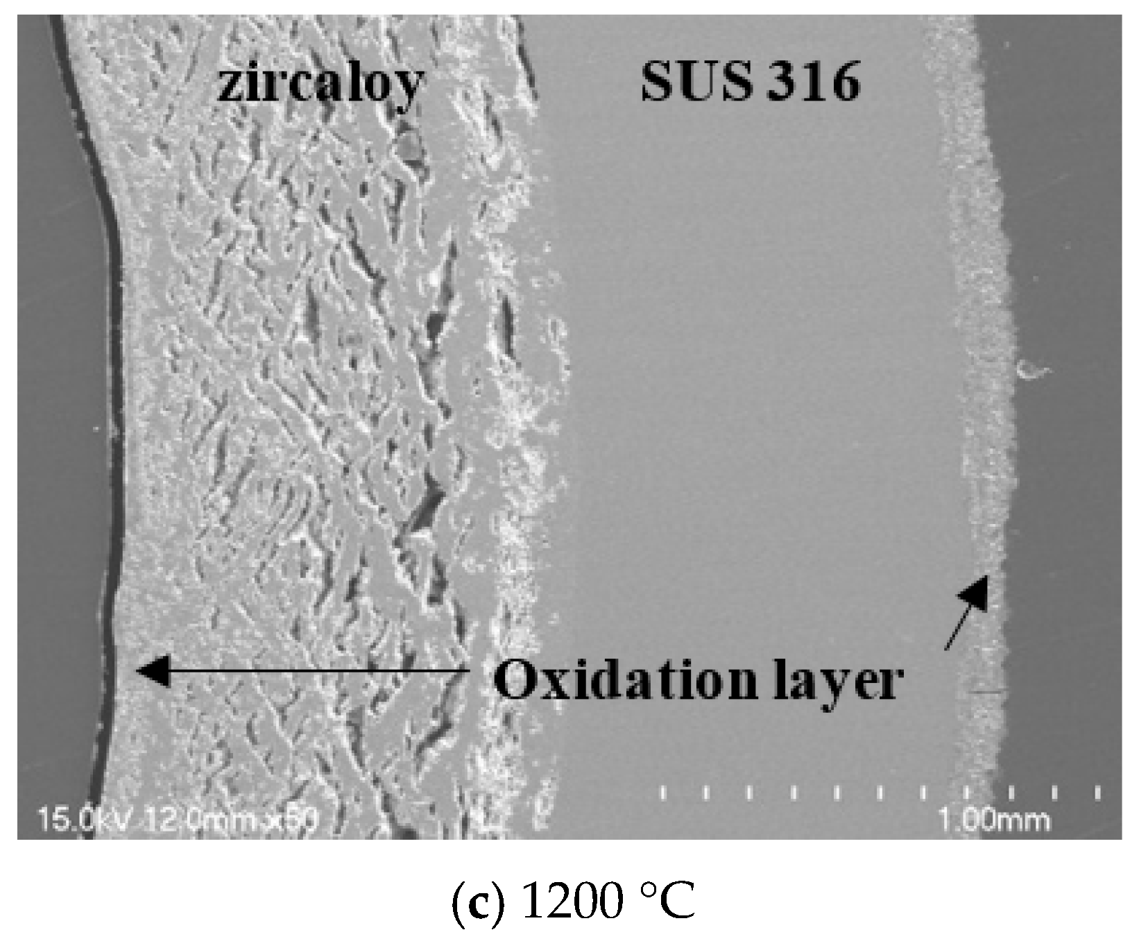
23]. Thermal shock tests of natural limestone concluded that its oxide layer is formed by an oxidation reaction at high temperatures. As the resulting oxide layer exhibits a large thermal expansion difference compared with the non-oxidized layer inside (owing to the differences in thermal shock received during cooling) and an immensely high amount of thermal stress accumulates at the interface between the oxide layer and the non-oxidized layer, the oxidized surface layer can be peeled off easily. In contrast, for the PST manufactured by the tube process, no surface peeling or structural failure was observed, even after heat treatment at 1200 °C. This is because the external material, SUS 316, which has a higher oxidation resistance than Zircaloy-4, inhibited the oxidation of Zircaloy-4 by preventing oxygen migration to the surface of Zircaloy-4. To observe the interface more clearly, the SEM analysis results of the PST cross-section before and after the heat treatment are shown in
Figure 9. No collapse was observed at the interface of the quenched sample after exposure at 600 and 900 °C. In contrast, at 1200 °C, the interface of the quenched sample showed exfoliation and porosity due to volume expansion. It is assumed that this is caused by a large amount of oxygen diffusion from the center of Zircaloy-4 to the interface between the two metals. However, even when the PST was exposed to 1200 °C, the oxidation reaction of the Zircaloy-4 surface was suppressed, along with subsequent structural collapse.
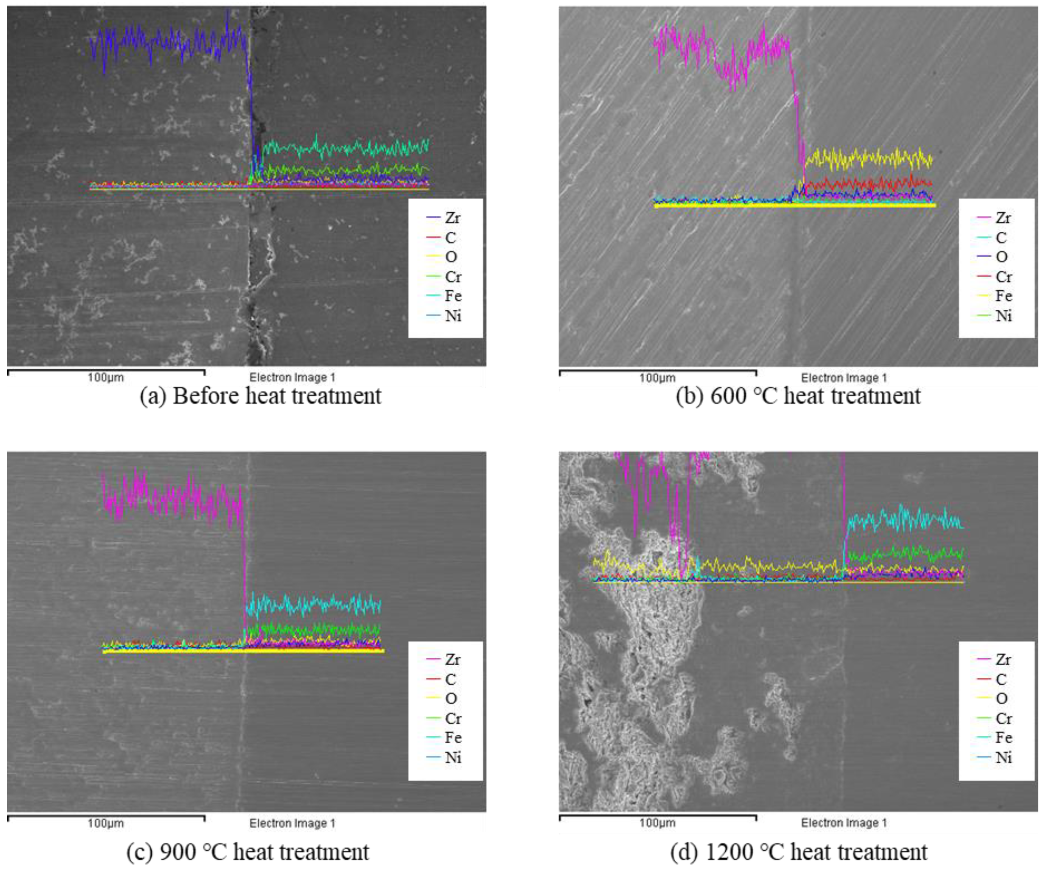
To confirm the diffusion behavior of the PST, an EDS analysis was conducted, as shown in
Figure 10. After heat treatment at 600 and 900 °C, the diffusion of Zr did not occur in the SUS 316 direction and no metallic elements of SUS 316 were seen in the Zircaloy-4 direction. Compositional analysis by EDS line scanning showed that the interface between Zircaloy-4 and PST did not degrade even when exposed to high temperatures. However, after heat treatment at 1200 °C, a well-known eutectic reaction caused an interdiffusion reaction, in which an Fe-Zr complex with a melting point of 928 °C was formed [
24]. Slight diffusion occurred at 1200 °C but it still exhibited high stability at operating and accident conditions. These results show that a PST consisting of a metal surface and Zircaloy-4 (e.g., 10Al-90Cr, etc.) [
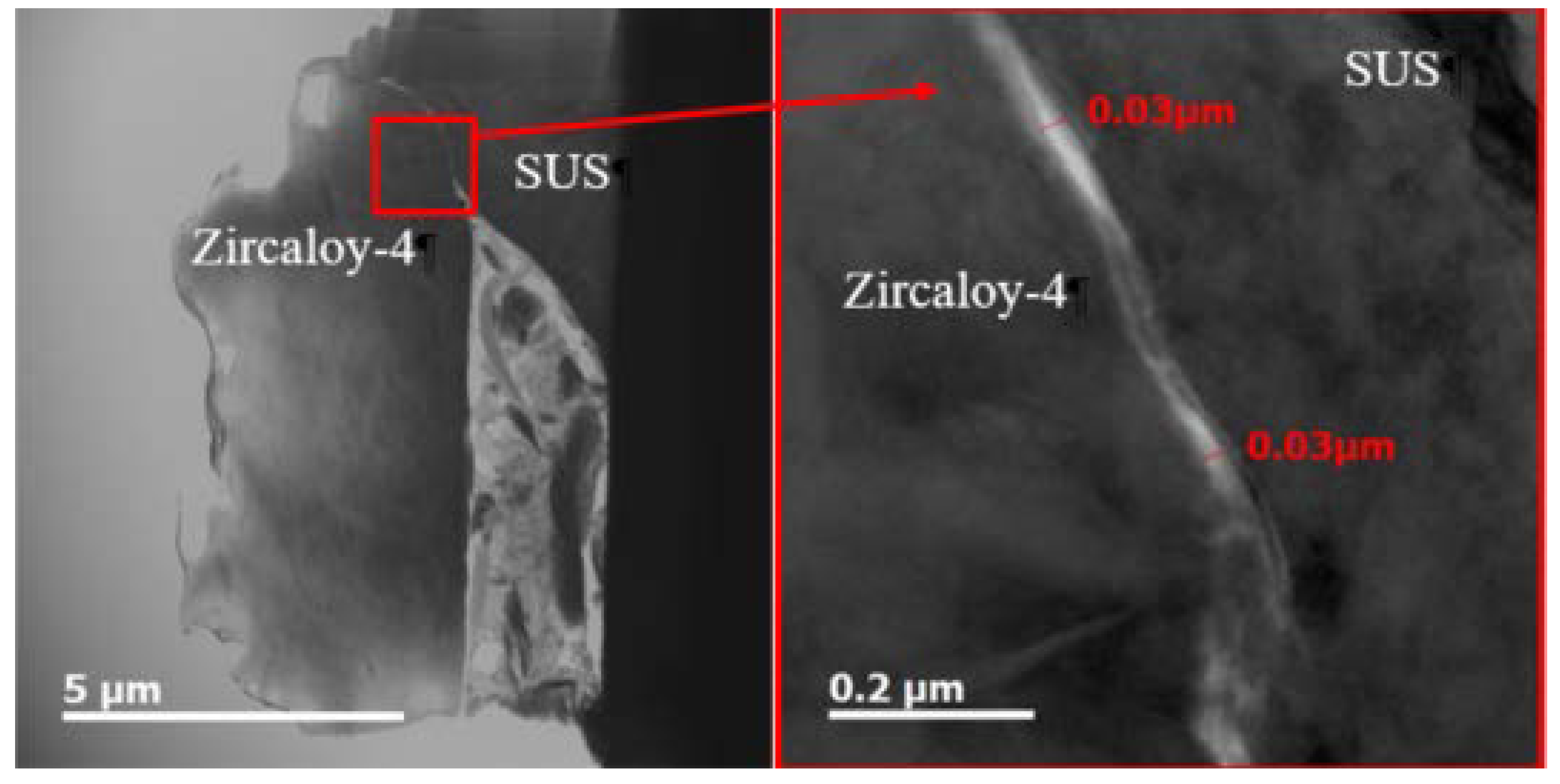
25], and fabricated using the tube process, has the potential to be used as ATF cladding. The interface of the sample, when exposed to 1200 °C, as well 600 °C and 900 °C, did not appear to peel off easily. From this, it can be concluded that an ATF cladding comprising the PST can maintain stability even at 1200 °C because the inside of the tube is isolated from external conditions during actual use. TEM analysis was performed to confirm the interfacial stability of the PST after exposure to high temperatures.
Figure 11 is a cross-sectional TEM image that shows the interfacial structure of Zircaloy-4/SUS 316 of the PST when quenched to room temperature after being maintained at 900 °C for 1 h. Rapid cooling to room temperature after exposure to high temperatures is generally well-suited for inducing significant thermal stresses at an interface to observe the physical stability of the interface. Images were obtained at three different magnifications to observe the interfacial condition over a wide range of PST cross-sections and nanoscale. The width of the PST interface was 0.03 µm (30 nm) after heat treatment, as elucidated from the highest-magnification images. Moreover, no new interface was formed between the secondary phase and each tube due to the interdiffusion of the two tube components. This is in good agreement with the results of EDS, shown in
Figure 10. Therefore, it is evident that the interface between two different tubes can maintain physicochemical stability, even when the PST formed by swaging is exposed to high temperatures. These results suggest that the development of several m-grade ATF claddings based on Zircaloy-4 is feasible, if conditions such as the type of tube used, its physical shape, and the optimum swaging pressure applied to the tube are established.
The results show that the tube process has a high potential for the development of an ATF cladding with a length of several meters, based on Zircaloy-4. The results suggest that controlling the compressive stress applied along the axial direction of the tube and the tensile stress occurring in the longitudinal direction will enable the facile and rapid development of ATF claddings, with their geometries calculated according to the design.


