Abstract
The paper presents an analysis of local and global forces acting on the ferromagnetic material of a modulator in a co-axial magnetic gear, taking several design variants and the impact of loading into account. The analyses include a modulator with cores manufactured from a soft-magnetic composite material and two variants made from electrical steel with laminations stacked in different directions. Variations of local forces acting on individual pole pieces of the modulator are analyzed at different loads, showing that the force spectra are subject to significant variation with an increasing load. The presented magnetostatic analyses are extended by structural analysis that provides estimation of stress and displacement for the modulator assembled from additively manufactured acrylonitrile butadiene styrene (ABS)-plastic parts. The analysis carried out for the least favorable design case of the magnetic circuit of the modulator shows that an application of the technology is significantly restricted by the magnetic gear torque volumetric density. Some changes to the modulator mechanical design are proposed in the paper to mitigate the drawbacks of this technology.
1. Introduction
Permanently rising energy prices and service costs enforce the use of high-efficiency energy conversion systems, with operating costs maintained to be as low as possible. The adjustment of the parameters of energy transformation (both mechanical and electrical) to the requirements of a specific application is substantial. Until the end of the 20th century, a diversified group of mechanical transmissions undoubtedly played the most important role in this respect. The publication of two studies [1,2] initiated a change in the state of the art. Research carried out globally over the past two decades has resulted in numerous alternatives to the classic solutions, in the form of magnetic gears (MGs) containing high-energy permanent magnets (PMs). The interest in MGs resulted from their characteristic features, i.e., natural overload protection, lack of friction between cooperating elements, thus leading to reduction of both losses and service requirements (including lubrication), and high efficiency [3,4,5,6,7,8,9,10,11]. Torque density values achieved by the currently known MGs, in some areas, are sufficiently high to allow replacement of mechanical gears. Such converters can be used in places that are difficult to access, where continuous and trouble-free operation is expected, or where there is a need to separate active and passive systems. Potentially attractive MG applications include wind and water turbines, and propulsion of ships or land vehicles [5,12,13].
An interesting converter, from the point of view of construction and movement properties, is the co-axial MG (CMG), in which ferromagnetic pole pieces distributed evenly in the space between the rotors (low and high speed) play a key role. Related to the number of pole pairs of high-speed and low-speed rotors, ph and pl, respectively, the number of ferromagnetic pole pieces ns must be equal to their sum. A modulator constructed in such a way allows the creation of appropriate harmonics in both air gaps, coupling the rotor magnetic field. Treating the internal rotor as the passive (driven) rotor and, depending on the choice of the active (driving) shaft in the form of either an external rotor or modulator, the gear ratio is equal to either Gr1 = −pl/ph or Gr2 = 1 + pl/ph respectively. The CMG, according to the configuration resulting in the ratio Gr1, also allows the direction of rotation of the rotors to be changed, which is indicated by the sign “minus” [1].
To date, all construction aspects of CMG rotors have been described relatively broadly, including the type and geometric parameters of PMs and the direction of magnetization. The impact of the shape and materials used to build the modulator have also been described in detail, in relation to the obtained characteristics and torque pulsations. In addition, the study of losses and transmission efficiency [14,15,16,17,18] has focused on the assessment of CMG properties, with modulators containing magnetic bridges, emphasizing their beneficial effect on torque characteristics and reduction of higher harmonics in the magnetic flux. The authors of [19,20] draw attention to the need to analyze these transducers for the possibility of unbalanced magnetic forces (UMF). This issue is particularly important for CMGs with fractional gear ratios when the conditions gcd(2ph, ns) ≥ 2 and gcd(2pl, ns) ≥ 2 are unfulfilled. For such configurations, the radial component of significant value is responsible for the increase in the level of vibration and noise as it also appears in the absence of geometric centricity. By reducing the presence of UMF through selecting the appropriate gear topology, there is a risk of an increase in the value of the cogging torque, so other methods should be sought to limit its presence [20]. The cited test results suggest the need for extreme caution when choosing the combination of the number of rotor pole pairs and the modulator pole pairs for a given gear.
The vast majority of the research to date is based on the characteristics of global torque as an indicator of CMG construction, but local phenomena that may be relevant depending on the construction of the modulator have been omitted. One of the attempts to analyze and assess the impact of individual components of the CMG modulator is presented in [21]. Based on the Maxwell stress tensor (MST) method, the authors propose decomposing the global torque acting on the modulator into components associated with individual ferromagnetic pole pieces and magnetic bridges. The presented test results confirmed the participation of all pole pieces of the modulator in the transformation of the torque, and allowed the authors to determine the structure of the modulator potentially most exposed to mechanical damage. In [22], the authors went one step further by presenting the structural analysis of magnetically geared machines and techniques for limiting torsional shear stress using an epoxy resin filling.
A contemporary approach to the problem of prototyping and creating new products used in modern industry successfully uses additive manufacturing (AM) techniques [23,24]. This trend also applies to the production of electric machines, and powder bed fusion technology is particularly promising in this context, due to the use of both structural and insulation elements (plastic), as well as electrically and magnetically active elements (ferromagnetics). The leading approaches in this field are the technologies of direct metal laser sintering (DMLS), selective laser melting (SLM), or selective laser sintering (SLS). In this context, fused deposition modeling (FDM) technology also offers significant advantages.
Bearing in mind the relatively low number of publications describing and taking into account the local distribution of forces/torque, the main goal of this work is to present analyses that complement this state of knowledge. In particular, we focus on comparing the impact of geometric and material parameters of CMG modulators in the context of magnetic interactions, taking into account the effects associated with changes in transducer load. We analyze in detail the local forces in the vicinity of the isotropic pole pieces and the anisotropy resulting from the lamination direction in the context of the AM technology used for the manufacture of nonmagnetic support parts of the modulator.
This work is divided into four main parts, beginning with a discussion of the basic features of CMG as the main research object and differences in the construction of the analyzed variants of modulators. The next part contains a description of the methods and tools used in the calculation of the distribution of local forces, simulation results, and the constructed measuring stand on which the measurement verification was carried out. The following section contains a detailed analysis of the impact of MG loading on the variation of radial and tangential components of local forces acting on individual modulator poles. The work is completed with a three-dimensional modulator model for which strength analysis is carried out under the least favorable loading conditions.
2. Physical Model
The subject of research in this work is the CMG extensively described in [18]. The gear cross-section and the most important geometrical parameters are shown in Figure 1a and in Table 1. The converter was built on the basis of 5-mm-thick N35 unsegmented neodymium magnets. The high-speed rotor was made in the form of a solid steel shaft on which the above-mentioned permanent magnets making two pairs of poles (ph = 2) were glued. The low-speed rotor, owing to the need to reduce power losses due to eddy currents, was made of a M400-50A steel sheet-pack and equipped with 16 permanent magnets (pl = 8). The modulator (ns = 10), due to the principle of operation, was designed in three variants (Figure 1b–d) differing in geometry and material used. According to the relationships presented in Section 1, in the conditions described it is possible to obtain gear ratios of 4:1 and 5:1. The considerations contained in this paper apply to the first configuration—with the modulator locked. This condition of operation occurs when the gear loses synchronism.
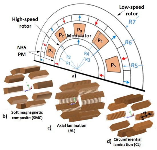
Figure 1.
Co-axial magnetic gear (CMG) geometry and modulator cores corresponding with designs, (a) the most important parameters, (b) SMC, (c) AL, (d) CL where “∥” and “⊥” are longitudinal and transverse stacking directions for the laminated designs, respectively.

Table 1.
Design parameters of the magnetic gear.
The special role played by the modulator in the magnetic gear potentially creates the most constructive constraints. The need to ensure high magnetic permeability of the ferromagnetic pole pieces, and the lowest possible electrical conductivity and high mechanical strength, is an important issue. Design solutions of the modulator’s nonferromagnetic parts were built using 3D additive manufacturing, and were characterized by generally lower mechanical strength of elements compared to conventional construction materials. A modulator structure should guarantee good CMG movement parameters and, at the same time, possibly low power losses. The soft magnetic composite (SMC) used in the first variant (Figure 1b) has conductivity of σ = 2500 S/m. Replacing solid steel with a composite material, with about 2000 times less conductivity, virtually eliminates eddy current losses in the modulator [18]. An alternative to the SMC material that is highly susceptible to mechanical damage is a modulator made in the form of a steel laminate with axial (Figure 1c) and circumferential (Figure 1d) stacking. In particular, the overwhelming proportion of available global research concerns CMGs with axially stacked modulators containing thin magnetic bridges between the cores. This structure is relatively easy to assemble and guarantees a low level of losses with only a slight reduction of the transmitted torque. The disadvantage of such a fragile modulator structure, however, is the high susceptibility to deformation of individual sheets during assembly of the package, although a small cross-section of magnetic bridges is determined by the electromagnetic design. High saturation, and thus a significant increase of magnetic reluctance in these areas, has little effect on the amplitudes of useful flux density harmonics in air-gaps while reducing higher harmonics responsible mainly for losses [25]. The last of the analyzed modulator structures (Figure 1d) allows for easy assembly of the sheet stack and avoids the use of magnetic bridges. This type of packaging, however, requires consideration of the magnetic orthotropy resulting from the way the sheets are stacked and is characterized by slightly higher eddy current losses. It should be added that such a variant of the modulator causes higher variation of air-gap equivalent reluctance than in the two other variants. The cross-section of the cores is rectangular but such variation can be diminished by vertical arrangement of individual sheets ensuring more uniform width of the air gaps.
3. Calculation and Verification of Forces and Torques
Currently available IT tools and hardware resources allow detailed calculations to be performed even for very advanced physical problems. Three-dimensional modeling, however, involves significant computational effort. The specificity of the converter described in this work, with due caution, however, allows the use of two-dimensional models. The description of the magnetic field in the static calculations for this CMG is essentially identical to those of the SMC and AL modulators, and leads to the solution of Equation (1).
where is the magnetic vector potential, is the magnetic flux density, is the magnetic reluctivity tensor, is a coercivity magnetic field strength, and the subscript denotes the z-th component of vectors.
A certain complication in the description is created by the specific arrangement of cores used in the circumferential lamination (CL) modulator, which enforces the necessity of using the reluctance tensor in Equation (1). The orthotropy resulting from the way the sheets are arranged in the longitudinal and transverse directions in the field model must additionally take into account the transformation resulting from the rotation of individual cores around the center of symmetry of the converter [18]. The reluctance tensor after taking into account the transformations related to the transformation matrix can be described by Equation (2).
where and are magnetic reluctivities in longitudinal and transverse stacking directions, respectively, and represents an angle between axis x of the global system of coordinates and the longitudinal direction axis.
Substituting the tensor reluctivity in Equation (1), we get the general form of the equation to be solved with respect to the potential of , and consequently also the magnetic induction B in the entire computational area. Considering Equation (2), Equation (1) becomes:
in ferromagnetic elements except permanent-magnets,
in permanent magnets, with being reluctivity of vacuum.
The solution of Equation (3) was carried out using our own software as neither of the nonlinear finite element packages known to the authors solves problems described by Equation (3a).
The majority of papers published to date are based on the analysis of torques obtained with the help of the Maxwell stress distribution in air-gaps. A research aspect of interest to the authors of the current work is a detailed analysis of forces acting at the local level, however, over the whole structure of the modulator. The general form of the 2D Maxwell stress tensor in the Cartesian coordinates system can be written in the form:
The distribution of force density for a specific object can be described by the divergence of Maxwell stress tensor in adjacent air-gaps:
The resultant force is obtained by integrating the expression of Equation (5) in the volume V occupied by the object. The application of Gauss’s theorem allows the conversion of the volume integral to the integral over a closed surface, from the product of the scalar tensor and the unit vector n, normal to the integration surface.
Based on Equation (6), for each of the modulator pole pieces (Figure 1b,d) it is possible to determine the local forces acting on individual walls of the object (Figure 2a). The sum of forces determined on the walls () of individual pole pieces will allow the resultant force to be obtained. For the modulator with a core structure containing a common bridge (Figure 2b), the force () associated with magnetic bridges was separated.
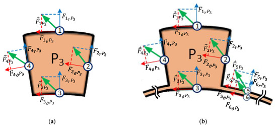
Figure 2.
Location of vectors representing local forces on individual walls of modulator segments for modulators: (a) SMC and CL; (b) AL; P3 represents the pole piece ordinal number as shown in Figure 1.
The CMG analyzed in this paper is characterized by a relatively small and, importantly, overall gear ratio (4:1), so the symmetry of the magnetic circuit eliminates the possibility of UMF. Bearing in mind only the steady-state force interactions, the greatest forces apply to the modulator when one of the rotors is locked. As was mentioned in the Section 2, this condition is not the usual state of operation of the CMG, but occurs at overload when synchronism is lost. It is, therefore, the state of operation with the greatest impact from the point of view of the mechanical structure of the modulator. Moreover, unlike the maximum load condition (which is not attainable due to stability restrictions) the torque in this condition can easily be measured on a laboratory test-stand.
The specificity of this state of operation does not allow limiting the analyses to one pole (which is possible in normal CMG operation), but forces the characterization of all pole pieces, which is naturally restricted by the periodic symmetry of the object. With this in mind, in this part of the work, the authors present the characteristics of local forces (walls 1–4) as a function of the rotation of the high-speed rotor for gears with a modulator with the SMC variant. The initial angular position of the rotors for this analysis and the numbering of the pole pieces are shown in Figure 1.
The results of computations are depicted in Figure 3 and Figure 4. As expected, the highest amplitudes of radial components apply to cylindrical surfaces 1 and 3 (see Figure 3), while the tangential components apply to side walls 2 and 4 (Figure 4) of the pole pieces. The greatest amplitude of radial components applies to cylindrical surfaces 1 and 3 of the P3 pole piece, while for tangential components it is visible for the P1 and P5 pole pieces. The angular asymmetry of individual force components is also visible in the case of poles P1 and P5, as well as P2 and P4, which allows limiting the analysis of resultant forces to three pole pieces located one after another (one-quarter of the considered CMG).
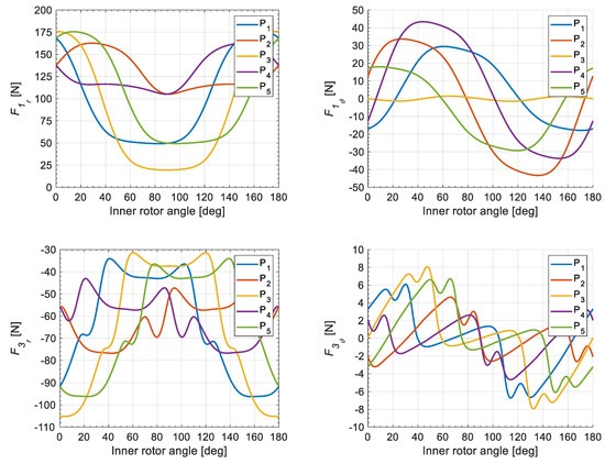
Figure 3.
Radial and tangential components of local forces on surface 1 and 3 for cores P1–P5 of the SMC modulator.
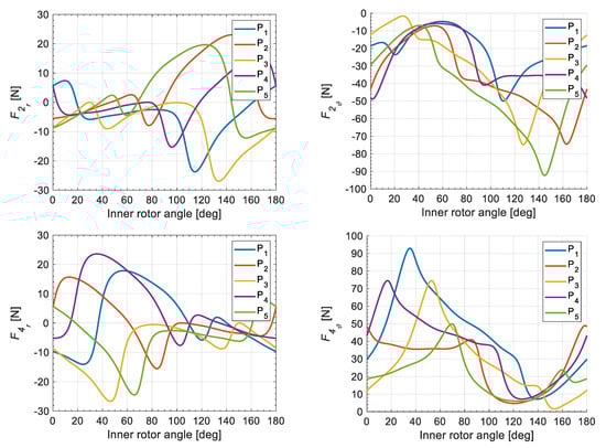
Figure 4.
Radial and tangential components of local forces on surfaces 2 and 4 for cores P1–P5 of the SMC modulator.
Other information important from the construction point of view was obtained from FFT analysis for P1–P3 cores. The spectra presented in Figure 5, obtained after summing up the local components on particular walls (1–4), indicate that the local fractions Fr and Fϑ are subject to significant variations. This is particularly important in the case of the radial component for the P3 core—where a large second harmonic also suggests a change in the direction of the radial force—responsible mostly for vibration and noise. The high value of the zero component with a relatively low level of remaining harmonics puts the P2 core in a much more favorable situation. Very similar levels of amplitudes of the harmonic multiple of No. 4 are visible for all cores.
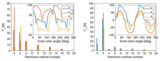
Figure 5.
Radial and angular (tangential) components of the resultant forces for P1–P3 cores of the SMC modulator and their FFT spectra.
Analyzing the tangential components, it can be seen that there is no zero component for the P3 core, which results from its characteristic location. Bearing in mind the verification of the received force values, the authors attempted to verify the obtained simulation results by measurements of global torque. By summing up the tangential components for all cores of the modulator on the basis of Equation (8), the torque on the modulator can be determined. Alternatively, based on the Maxwell tensor in air-gaps, calculations were carried out on the torque on the modulator as the sum of the torques acting on the internal and external rotors. In addition, torque calculations were also carried out based on the virtual work principle [26].
The measurements were carried out using the stand shown in Figure 6a, equipped with two torque transducers and a stepper motor with a planetary mechanical gear and a precise data acquisition system. The simulation results were confronted with measurements carried out on a real object for all types of modulators and are summarized in Figure 6b and Figure 7. In all cases, acceptablly good agreement of calculations with the measurements was obtained, which confirms the correctness of the method of force calculation.
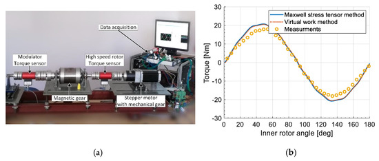
Figure 6.
(a) Measurement stand; (b) comparison of calculations with measurements for MG with SMC modulator.
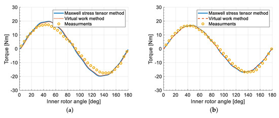
Figure 7.
Comparison of calculations with measurements for MG with: (a) AL modulator, (b) CL modulator.
4. Impact of Load on Local Forces
The results presented in the previous chapter showed the presence of relatively high local forces affecting the modulator. However, they only include the specific, rather undesirable operating state of the MG with the outer rotor blocked, which has some analogy to a short-circuit condition as in electric machines. A characteristic feature of this state is the uneven distribution of forces on pole pieces of the modulator, as a result of which it was necessary to carry out an analysis of several cores. In the state of normal operation, the synchronism-constrained angular displacement of the rotors allows the reduction/limitation of analyses to just one pole piece due to the symmetry/periodicity of the magnetic field. Bearing this in mind, the authors limit themselves to analyzing one of the modulator’s segments (pole pieces), taking into account the variation of forces in relation to the pole pitch of the inner rotor.
One of the important aspects relatively rarely examined in the literature is the analysis of the impact of load on the work of the CMG. As is well known, the efficiency of magnetic gears is high and reaches typically 95–99% [4,18]. The use of steel lamination or SMCs, segmentation of permanent magnets, and avoiding fringing effect of the magnetic field in the magnetic circuit, significantly reduces losses in such a converter. However, one cannot overlook components strongly dependent on rotational speed, i.e., losses associated with eddy currents and viscous friction. The relationship describing the MG efficiency is also a function of the torque and has the characteristics of a saturation binding curve approaching the limit along with the rotational speed [18]. This relationship is reflected in the harmonic spectrum of the tangential component of local force for all the analyzed variants of modulators (Figure 8, Figure 9 and Figure 10). Apart from the natural increase of the constant components visible in all the variants, the deserving attention (due to magnetic orthotropy and heterogeneity of the air gap) is the lack of major changes in the 4th harmonic for the CL modulator. A clear, more than three-fold increase of the 4th harmonic value for SMC and AL modulators progresses with increasing load. The tangential component associated with magnetic bridges, which is present in the AL modulator, practically does not occur. Thus, as expected, this element does not participate in the transmission of torque.
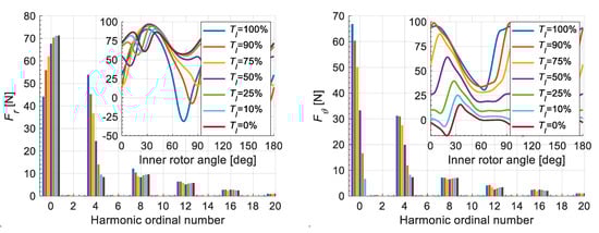
Figure 8.
Force components acting on a selected SMC modulator core.
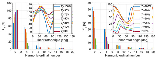
Figure 9.
Force components acting on a selected AL modulator core.
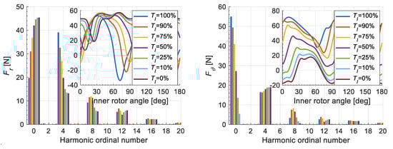
Figure 10.
Force components acting on a selected CL modulator core.
Vibroacoustic analysis is a particularly important issue for modern transducers. As shown in [19], the presence of UMF significantly reduces the advantages of the MG converter. The presence in the harmonic spectrum, of substantially dominant frequency, depending on rotational speed, confirms the essential drawback of the magnetically unbalanced converters. The selection of another combination of rotor pole pairs and a modulator is crucial at this point. Undesirable vibrations are the result of local radial forces and occur in each transducer, even in those that are magnetically symmetrical. The key issue is to manufacture a key element of the CMG, a modulator, so as to keep its stiffness as high as possible. In the analyzed CMG, in global terms, the modulator is fully balanced, i.e., radial forces acting on opposite cores cancel each other out.
The prototype constituting the subject of this work was built using 3D printing for the nonferromagnetic parts of the modulators. However, during the standard laboratory tests carried out on the physical test-stand, the prototype was noisier than that manufactured traditionally. Therefore, the authors identified the cause of this phenomenon in the reduced elasticity of the mechanical structure of the modulator in response to local forces. With this in mind, the authors of this work also performed calculations of the radial component of local magnetic forces. Additionally, an important issue from the point of view of the authors of this work, not discussed in the literature to date, is the analysis of the impact of load on the angular variations of these components. In the analyses reported in the literature, the only condition of operation is maximum load.
When analyzing the results of calculations for three variants of modulators, a clear increase in the constant component of radial force for the AL modulator core was observed. Unlike for the other modulators, this force does not change the sign, which means that the core is attracted to the external rotor. For the remaining variants of the modulators, it can be seen that the increase in load in extreme cases also affects the change in the direction of the radial force. The amplitudes of fourth harmonics in all cases significantly increase (approx. three-fold) with increasing load, which should result in an increase in the vibration level; this was also noted on the measuring stand. The ordinal number equal to 4 is a result of the CMG configuration with the high-speed rotor pole-pair number equal to 2, as the radial force is in proportion to the square of the magnetic flux density.
The significant reduction of other higher harmonics for the AL modulator is also noteworthy. When analyzing the radial force acting on magnetic bridges, it was observed that, for the whole range of variations, they are attracted to the internal rotor, and the change in load does not significantly change the nature of this force (Figure 11). Considering the small active cross-section of the jumpers and the relatively high values achieved by the radial component in points, these bridges are potentially the most vulnerable points of the modulator.
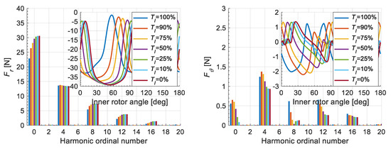
Figure 11.
Components of forces acting on the selected modulator bridge with AL structure.
5. Structural Analysis
The need for application of structural analysis of flux-modulated converters has already been demonstrated in the literature [22]. The analysis presented in the reference paper relates to a converter different to that analyzed here. In addition, the presented structural analyses concern the modulators manufactured more traditionally. Here, we provide analysis of the problems that arise when additive manufacturing is involved.
The three variants of modulators considered in this paper differ significantly in design. Definitely, the most susceptible to damage is the variant containing the SMC. The high electrical resistivity of the composite and good magnetic properties do not correspond with good strength properties as in the case of M400-50A sheets. The authors of this work, in parallel with the two-dimensional magnetic field calculations, also prepared three-dimensional structural models for strength tests. The modulators used in all considered variants, apart from the magnetically active parts, i.e., cores, were built on the basis of 3D-printings in FDM technology. Figure 12 shows an example structure of an SMC modulator made of cores (Figure 12a) with a positioning basket (Figure 12b) that is a printed element.
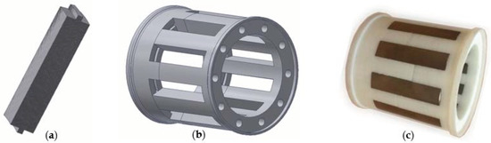
Figure 12.
Modulator assembly (a) Somaloy 700 ferromagnetic core; (b) CAD drawing of positioning basket showing bores where non-magnetic rodes are inset; (c) physical modulator assembly. The 3d-printed element has a white colour.
The positioning basket is composed of two parts (as shown in Figure 12c) that are compressed by 10 nonmagnetic and nonconducting rods inset into the bores. The materials of the ferromagnetic cores (Somaloy 700), bolts ((ABS)-plastic), and steel elements (mild steel) used in the simulation were defined as isotropic materials and their parameters are presented in Table 2. The positioning basket was defined as artificial composite, which exhibits the properties of orthotropic material. The parameters of the materials, which were determined using laboratory tests, are presented in work [27]. Authors took into account two types of 3D printing interior geometry, namely solid-fibrous (see Figure 13a) and honeycomb (see Figure 13b).
Table 2.
Material parameters.
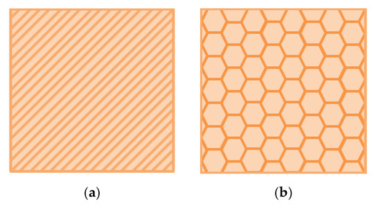
Figure 13.
Types of 3D-printed material structures: (a) solid-fibrous, (b) honeycomb.
The basis for mechanical strength calculations was presented in Section 4 of this work, i.e., results of magnetic field force components. It should also be added that the modulator in this gear configuration was a fixed element, which eliminates the need to take centrifugal force into account. To carry out the strength analysis of the modulator, Nastran IN-CAD software was used. During the simulation, the modulator model implemented boundary conditions as shown in the Figure 14, where T—translation and R—rotation.
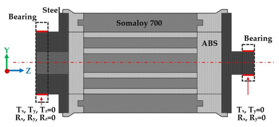
Figure 14.
Modulator model with imposed boundary conditions.
According to Figure 8, the maximum value of radial forces (Fr = 96.97 N) acting on the pole pieces of the SMC structure modulator is obtained for a load of Tl = 50%. Therefore, the authors of the work present the results of static analysis carried out for this load variant and also for maximal load. Figure 15 shows the model of the modulator assembly with the values of tangential and radial forces assigned to the pole pieces of the modulator in accordance with Table 3. The values correspond to the forces obtained at each pole at the same angle of rotation of the inner rotor. The entire modulator was meshed obtaining 57,890 elements and 105,284 nodes.
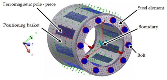
Figure 15.
Modulator model with assigned boundary conditions and marked force vectors.
Table 3.
Values of surface forces acting on the poles of the modulator imposed on the model in Figure 15.
The reduced tensions according to the Huber-Mises-Hencky hypothesis showing the material strain in multi-axis stress states and the resulting displacements are presented in Figure 16. As a result of the static analysis for the maximum radial force acting on the modulator pole pieces, a maximum reduced stress σred was obtained at a level of 7.51 MPa, with the corresponding maximum displacement of 0.02 mm for the positioning basket with solid-fibrous geometry, and 10.22 MPa, with the maximum displacement of 0.06 mm for the positioning basket with honeycomb geometry. The indicated maximum reduced stress values are related to the areas responsible for fixing the cores in the positioning basket. The resulting maps of reduced stress distributions for the two models of modulator assembly did not show areas in which the reduced stress of Huber-Mises-Hencky would exceed the accepted limits of yield for the used additive manufacturing technologies. However, the characteristic torsion resulting from the tangential forces responsible for the torque is visible in all drawings. This torsion is even more visible in Figure 17, which shows the displacements for the maximum gear load, Tl = 100%. The maximum value of displacements exceeding 0.1 mm is of the order of the 3D printing resolution alone and can cause local fatigue of the material, taking into account the pulsating nature of magnetic forces during MG operation. Looser fit of modulator components in the ABS material combined with this state of affairs can also be the cause of increased levels of vibration and noise.
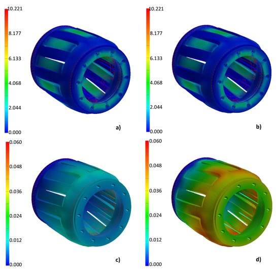
Figure 16.
(a,b) Results of static stress analysis in MPa at a load of Tl = 50% for the positioning basket with solid-fibrous and honeycomb geometries, respectively; (c,d) displacements in milimeters for the positioning basket with solid-fibrous and honeycomb geometries, respectively.
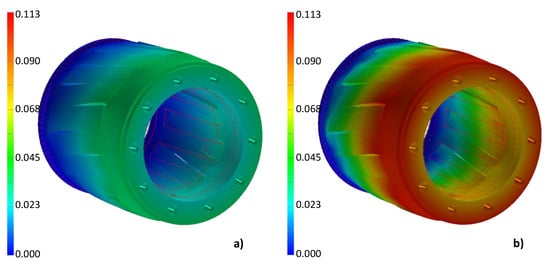
Figure 17.
(a,b) Results of displacements in millimeters at a load of Tl = 100% for the positioning basket with solid-fibrous and honeycomb geometries, respectively.
From the simulation, important information is obtained indicating that the SMC structure modulators with the material parameters and specified load meets the strength conditions. Moreover, the results obtained are the basis for developing modifications of the modulator basket geometry by making cutouts or holes. Changing the design of the modulator basket can reduce the amount of material used during the printing process while maintaining its full functionality. One way to eliminate the harmful effects of displacement of the cores, as shown in Figure 18, is a modulator with a layer of glass fiber mesh immersed in epoxy resin. This design solution additionally protects the fragile soft magnetic composite cores susceptible to mechanical damage during gear assembly, although it does not allow for reduction of the working air-gap length below 1 mm. In the case of modulators made in the form of a steel laminate with axial and circumferential stacking (Al and CL), it additionally protects against possible delamination and displacement of individual sheets. Due to the much greater rigidity and strength of laminated modulators, the authors do not include the corresponding results of structural analyses in this work.
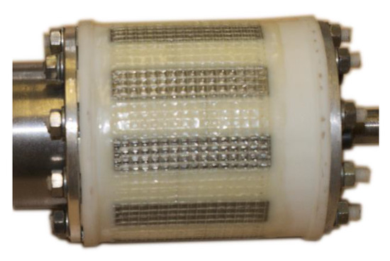
Figure 18.
Modulator with a layer of a glass fiber mesh immersed in epoxy resin as a means of increasing the rigidity of the modulator structure.
6. Conclusions
This paper provides analysis of local and global forces acting on material and geometric variants of co-axial magnetic gear modulators at different load conditions. Three alternative designs of modulators manufactured from soft magnetic composite and steel laminations, with axial and circumferential orientation, are considered. A description of the methods and tools used in calculation of the distribution of local forces is presented. Based on the Maxwell stress tensor, a method is proposed to decompose the global torque acting on the modulator into components associated with individual ferromagnetic pole pieces and magnetic bridges. The presented test results confirm the participation of all pole pieces of the modulator in the transformation of the torque, and allow the structure of the modulator potentially most exposed to fatigue wear to be determined. The results of the analysis contain detailed information on the impact of the design and the applied materials on variations of both local force components and magnetic torque of the magnetic gear.
The characteristics obtained from the study clearly indicate that the magnitudes of the harmonic spectra of the local radial forces increase with an increase of CMG load torque for all considered modulator designs. The local radial forces do not significantly contribute to displacement, but can affect vibrations. These problems are of special concern when the FDM additive manufacturing technology is used in connection with some designs of the magnetic circuit of the modulator, such as the variant in which the pole pieces are embedded in ABS plastic without any metallic connection between them. The presented study, which was carried out for a model with relatively short axial length, shows that for this type of design even in small CMGs, where the torque density is around 40 kNm/m3, the ABS-plastic-printed material may not withstand loads due to the nominal value of global torque. Therefore, this attractive technology should be applied very carefully and preferably be accompanied by other technologies with the potential to make the structure more rigid and fatigue-resistant.
Author Contributions
Conceptualization, M.K. and J.K.; methodology, M.K., J.K. and M.J.; software, R.G.; validation, M.K. and J.K.; investigation, M.K., J.K. and M.J.; resources, M.Ł.; data curation, M.K.; writing—original draft preparation, J.K.; writing—review and editing, M.J. and M.Ł; visualization, M.K., J.K. and R.G.; supervision, M.K. and J.K.; project administration, M.K. and J.K.; All authors have read and agreed to the published version of the manuscript.
Funding
This research received no external funding.
Conflicts of Interest
The authors declare no conflict of interest.
References
- Atallah, K.; Howe, D. A novel high-performance magnetic gear. IEEE Trans. Magn. 2001, 37, 2844–2846. [Google Scholar] [CrossRef]
- Atallah, K.; Calverley, S.; Howe, D. Design, analysis and realisation of a high-performance magnetic gear. IEE Proc. Electr. Power Appl. 2004, 151, 135–143. [Google Scholar] [CrossRef]
- Rasmussen, P.O.; Andersen, T.O.; Jorgensen, F.T.; Nielsen, O. Development of a high-performance magnetic gear. IEEE Trans. Ind. Appl. 2005, 41, 764–770. [Google Scholar] [CrossRef]
- Tlali, P.M.; Wang, R.; Gerber, S. Magnetic gear technologies: A review. In Proceedings of the 2014 International Conference on Electrical Machines (ICEM), Berlin, Germany, 2–5 September 2014; pp. 544–550. [Google Scholar] [CrossRef]
- Belkhir, K.S.; Khenfer, N. Magnetic gear generator for wind energy. Electrotech. Rev. 2013, 5, 72–75. [Google Scholar]
- Gouda, E.; Mezani, S.; Baghli, L.; Rezzoug, A. Comparative study between mechanical and magnetic planetary gears. IEEE Trans. Magn. 2011, 47, 439–450. [Google Scholar] [CrossRef]
- Huang, C.C.; Tsai, M.C.; Dorrell, D.G.; Lin, B.J. Development of a magnetic planetary gearbox. IEEE Trans. Magn. 2008, 44, 403–412. [Google Scholar] [CrossRef]
- Jian, L.; Chau, K.T.; Gong, Y.; Jiang, J.Z.; Yu, C.; Li, W. Comparison of coaxial magnetic gears with different topologies. IEEE Trans. Magn. 2009, 45, 4526–4529. [Google Scholar] [CrossRef]
- Jorgensen, F.T.; Andersen, T.O.; Rasmussen, P.O. The cycloid permanent magnetic gear. IEEE Trans. Ind. Appl. 2008, 44, 1659–1665. [Google Scholar] [CrossRef]
- Rens, J.; Clark, R.; Calverley, S.; Atallah, K.; Howe, D. Design, analysis and realization of a novel magnetic harmonic gear. In Proceedings of the 2008 International Conference on Electrical Machines, Vilamoura, Portugal, 6–9 September 2008. [Google Scholar] [CrossRef]
- Zhu, D.; Yang, F.; Du, Y.; Xiao, F.; Ling, Z. An Axial-Field Flux-Modulated Magnetic Gear. IEEE Trans. Appl. Supercond. 2016, 26. [Google Scholar] [CrossRef]
- Shah, L.; Cruden, A.; Williams, B.W. A Magnetic Gear Box for application with a Contra-rotating Tidal Turbine. In Proceedings of the 7th International Conference on Power Electronics and Drive Systems, Bangkok, Thailand, 27–30 November 2007; pp. 989–993. [Google Scholar] [CrossRef]
- Frank, N.; Toliyat, H. Gearing ratios of a magnetic gear for marine applications. IEEE Electric Ship Technol. Symp. 2009, 477–481. [Google Scholar] [CrossRef]
- Evans, D.J.; Zhu, Z. Influence of design parameters on magnetic gear’s torque capability. In Proceedings of the 2011 IEEE International Electric Machines & Drives Conference (IEMDC), Niagara Falls, ON, Canada, 15–18 May 2011; pp. 1403–1408. [Google Scholar]
- Gerber, S. Evaluation and Design Aspects of Magnetic Gears and Magnetically Geared Electrical Machines. Ph.D. Thesis, Department of Electrical and Electronic Engineering, Stellenbosch University, Stellenbosch, South Africa, 2015. [Google Scholar]
- Abdelhamid, D.Z.; Knight, A.M. The Effect of Modulating Ring Design on Magnetic Gear Torque. IEEE Trans. Magn. 2017, 53. [Google Scholar] [CrossRef]
- Jing, L.; Liu, L.; Xiong, M.; Feng, D. Parameters Analysis and Optimization Design for a Concentric Magnetic Gear Based on Sinusoidal Magnetizations. IEEE Trans. Appl. Supercond. 2014, 24, 0600905. [Google Scholar]
- Kowol, M.; Kołodziej, J.; Jagieła, M.; Łukaniszyn, M. Impact of modulator designs and materials on efficiency and losses in radial passive magnetic gear. IEEE Trans. Energy Convers. 2019, 34, 147–154. [Google Scholar] [CrossRef]
- Agenbach, C.J.; Els, D.N.J.; Wang, R.; Gerber, S. Force and Vibration Analysis of Magnetic Gears. In Proceedings of the 2018 XIII International Conference on Electrical Machines (ICEM), Alexandroupoli, Greece, 25 October 2018; pp. 752–758. [Google Scholar] [CrossRef]
- Jungmayr, G.; Loeffler, J.; Winter, B.; Jeske, F.; Amrhein, W. Magnetic gear: Radial force, cogging torque, skewing and optimization. In Proceedings of the 2015 IEEE Energy Conversion Congress and Exposition (ECCE), Montreal, QC, Canada, 20–24 September 2015; pp. 898–905. [Google Scholar] [CrossRef]
- Jian, L.; Deng, Z.; Shi, Y.; Wei, J.; Chan, C.C. The Mechanism How Coaxial Magnetic Gear Transmits Magnetic Torques between Its Two Rotors: Detailed Analysis of Torque Distribution on Modulating Ring. IEEE/ASME Trans. Mechatron. 2019, 24, 763–773. [Google Scholar] [CrossRef]
- Fernando, N.; Saha, S. Torsional shear stress minimization techniques and implications on electromagnetic performance of flux-modulated double rotors. IEEE Trans. Energy Convers. 2018, 33, 49–58. [Google Scholar] [CrossRef]
- Wrobel, R.; Mecrow, B. Additive Manufacturing in Construction of Electrical Machines—A Review. In Proceedings of the 2019 IEEE Workshop on Electrical Machines Design, Control and Diagnosis (WEMDCD), Athens, Greece, 22–23 April 2019; pp. 15–22. [Google Scholar] [CrossRef]
- Tiismus, H.; Kallaste, A.; Belahcen, A.; Rassõlkin, A.; Vaimann, T. Challenges of Additive Manufacturing of Electrical Machines. In Proceedings of the 2019 IEEE 12th International Symposium on Diagnostics for Electrical Machines, Power Electronics and Drives (SDEMPED), Toulouse, France, 27–30 August 2019; pp. 44–48. [Google Scholar] [CrossRef]
- Gerber, S.; Wang, R.-J. Evaluation of a prototype magnetic gear. In Proceedings of the 2013 IEEE International Conference on Industrial Technology (ICIT), Cape Town, South Africa, 25–28 February 2013. [Google Scholar] [CrossRef]
- Benhama, A.; Williamson, A.C.; Reece, A.B.J. Virtual work approach to the computation of magnetic force distribution from finite element field solutions. IEE Proc. Electr. Power Appl. 2000, 147, 437–442. [Google Scholar] [CrossRef]
- Cader, M.; Oliwa, R.; Markowska, O.; Budzik, G. Producing mobile robot gripper part prototypes from polymeric materials using additive manufacturing technology. Part I. Mechanical properties and material constants of specimens from acrylonitrile-butadiene-styrene copolymer. POLIMERY 2017, 62, 27–35. [Google Scholar] [CrossRef]
- Somaloy 3P, Material Data, Hoganas. 2018. Available online: https://www.hoganas.com/globalassets/download-media/sharepoint/brochures-and-datasheets---all-documents/somaloy-3p_material-data_june_2018_2273hog.pdf (accessed on 1 April 2020).


© 2020 by the authors. Licensee MDPI, Basel, Switzerland. This article is an open access article distributed under the terms and conditions of the Creative Commons Attribution (CC BY) license (http://creativecommons.org/licenses/by/4.0/).