Performance and Sustainability Analysis of an Organic Rankine Cycle System in Subcritical and Supercritical Conditions for Waste Heat Recovery


Department of Aerospace Engineering, Faculty of Engineering, Universiti Putra Malaysia, Serdang 43400, Selangor, Malaysia
*
Author to whom correspondence should be addressed.
Energies 2020, 13(12), 3035; https://doi.org/10.3390/en13123035
Submission received: 11 May 2020
/
Revised: 31 May 2020
/
Accepted: 4 June 2020
/
Published: 12 June 2020
(This article belongs to the Section B: Energy and Environment)
Abstract
:This study addresses the performance analysis of a subcritical and supercritical Organic Rankine Cycle (ORC) with the addition of a preheater or superheater integrated with a turbofan engine. This analysis will try to explore the heat transfer throughout the evaporator for the purpose of determining the ORC output power and thermal efficiency. A simplified numerical model of the ORC for waste heat recovery is presented. The model depicts the evaporator by using a distributed model, and includes parameters such as the effectiveness, heat capacity and inlet temperature of the waste heat and the organic fluid. For a given set of initial parameter values, the output power and thermal efficiency, as well as the mass flow rate of the working fluid are acquired by solving the system’s thermodynamic cycle with the aid of MATLAB software. The model is then verified by using data from an industrial waste heat recovery system. The connection between the turbofan engine and the ORC system was established and evaluated by means of Thrust-Specific Fuel Consumption (TSFC) as well as fuel burn. It was found that the supercritical ORC with a preheater and superheater exhibits lower TSFC than the subcritical ORC, whereas the impact of the ORC in terms of waste heat recovery in relation to the environment and sustainability indices is quite small, but still considerable depending on the engine’s weight.

1. Introduction
In general, one third of energy is consumed by the industrial sector. However, more than 50% of this energy is wasted as heat [1]. Waste heat is hard to identify and evaluate in terms of quality and quantity, as it is not clearly visible like material waste. Due to global energy interests and responsibilities, as well as the opposition to the consumption of energy-rich fossil-based fuels, we must find ways to overcome this energy-saving issue. One of the most promising solutions is the waste heat recovery (WHR) method. Waste heat is defined as the unused heat developed throughout the chemical reaction or combustion process, which is instantaneously drained to the surroundings. There are several advantages in converting exhaust heat into useful power, for example it can help to reduce fuel consumptions, improve engine power density, and further decrease carbon dioxide (CO2) and other harmful exhaust emissions. Among the available bottoming cycle methods, steam or Rankine cycles are undoubtedly the most reliable options, although they may be not the most efficient ones [2,3,4,5].
The Organic Rankine Cycle (ORC) is one type of WHR system, which works on the principle of the Rankine cycle, where a working fluid is transported through four basic components. This allows the waste heat to be converted to useful power. Although ORC has many disadvantages such as the fact that the fluids used in an ORC cycle are combustible and, if leakages occurred, an environmental hazard could result, and the fact that ORCs are more expensive than water, the selection of organic fluids over water brings a lot of advantages to the system compared to the steam cycle. The possibility of the transformation of low temperature heat into useful electrical energy is high and can be effective based on its thermophysical characteristics—for instance, a low boiling temperature, low critical point, and high molecular mass.
The analysis of supercritical fluid parameters is crucial. It is proven to perform higher efficiencies which are more attractive for waste heat applications [6]. In supercritical ORC, the vapor is expanded in the turbine at slightly superheated conditions. Unlike the subcritical ORC, the heating process does not pass through the two-phase (liquid and vapor) regions. This leads to a lower difference in temperature in the evaporator between the hot and cold fluids with a lower irreversibility. In supercritical condition, the ORC thermal efficiency could be improved by 10–30% due to the increment of specific work output, since the heat is added to the working fluid at supercritical pressure [7,8,9]. As a result, the loss in exergy will eventually become lower [10]. However, the challenge lies in the unpredictable process of heat transfer in the evaporator since the properties of the fluid are variable to the temperature [11].
Various design configurations have special benefits and constraints. They differ in their construction complexity and performance while operating under distinctive applications and thermal conditions. Daniel R.M. [12] mentioned that more waste heat can be recovered when a superheater is attached. However, an extra weight is also added since, in order to transfer energy, and for the cooler to be able to condensate the organic fluid, a larger area is needed. Boz B. et al. [13] performed a study to compare the performance of subcritical and supercritical ORC in exhaust heat recovery. There are two configurations presented, the Regenerative ORC (RORC) and Preheating-Regenerative ORC (PRORC). The greatest net power output by using R245fa was found to be 203.1 kW at around 36% of efficiency with the RORC system. This was due to the increase in turbine inlet temperature that led to the total net power output increasing. In subcritical cycles, the RORC and PRORC showed lower thermal efficiency and power output compared to supercritical cycles. Yagli H. et al. [14] have done a study on the net power production, mass flow rate and system thermal efficiency of an ORC system with additional preheater and superheater, applied to a power plant using R245fa as working fluid. From the results, the supercritical ORC gives better net power and thermal efficiency at 81.52 kW and 15.93% compared to the subcritical ORC at 79.23 kW and 15.51%. Gao T et al. [15] studied the performance of subcritical and supercritical ORC in Geothermal Power Systems. The results from this study indicate that ORC at a supercritical condition has better output power with 480 kW compared to subcritical ORC with only 450 kW. Yang M.H. et al. [16] evaluated on the performance of an ORC system with the addition of both a superheater and a preheater applied to a marine engine. By using R245fa as the working fluid, a net power output of 87.05 kW and a thermal efficiency of 10.08% are achieved.
The energy consumption and environmental impacts have increased with the growth of the aviation industry. Many researchers have attempted to increase the power and decrease the consumption of fuel and the noise of engines in aircraft [17]. Actions have been taken by the aircraft designers and engineers to enhance the fuel efficiency by changing the aircraft system and fuel types. In order to enhance an aircraft engine’s thrust, it is possible to recover the engine core’s exhaust heat and reuse it to produce useful power. The ORC system applied to a CFM56 turbofan engine’s system demonstrated a 0.9% (by considering additional weight of WHR) to 2.5% (without additional weight) benefit in relation to the vehicle’s fuel burn [18]. However, due to concerns about resources and time, some assumptions for the modeling are made. A fixed heat transfer coefficient was used, pressure loss was only assumed within the turbine and they estimated the fixed core exhaust flow to the evaporator as 30%, although the fluid was changed while the engine was running. De Servi et al. [19] have also investigated the possibility of recovering waste heat using supercritical carbon dioxide (sCO2) as the working fluid. They found that the reduction in Specific Fuel Consumption (SFC) with respect to the SFC of the GE90-94B turbofan engine is about 2.8%, which is nearly one of order of magnitude lower than the value predicted by the sole thermodynamic cycle analysis. Moreover, the model does not take into account the additional fuel consumption due to the weight of sCO2 WHR unit. Another approach to reduce the SFC was outlined by O. Petit et al. [20] on an intercooled turbofan engine by recovering the waste heat from the intercooler and reusing it to generate useful power. They achieved a maximum SFC improvement of 3% by using this method.
In order to account for the sustainability of an aircraft engine, exergy plays an important role. According to Sohret Y. et al. [21], the number of studies covering the aspect of exergy for aircraft engines has increased in the past six years. The exergy efficiency increases at high altitudes due to the decrease in temperature and pressure. However, the exergy efficiency is decreased when the flight is taking off, then starts to climb and during landing [22]. Turgut et al. [23] performed an analysis of a turbofan engine based on exergy with an afterburner at sea level and 11000 m altitude. They concluded that, in the exhaust section, a major portion of the exergy is lost due to a higher temperature and velocity in the exhaust of the stream. Meanwhile, Tona C. et al. [24] presented an analysis of a turbofan engine for commercial flights based on exergy. According to the results, the maximum exergy efficiency was achieved while the flight was cruising, with a value of 26.5%. Their analysis also showed that 50.66% of the total destroyed exergy occurred within the combustion chamber and the exhaust. Turan O. et al. [25] focused on a detailed exergetic analysis of a high bypass turbofan engine and revealed that the exergy efficiency of the engine was 29.6%. In addition, 1.48 and 0.675 were achieved, respectively, for the exergetic sustainability index and environmental effect factor of the engine. Later on, they proceeded with their investigation on a low bypass turbofan engine and found the exergy efficiency to be 11%, while 3.163 and 0.316, respectively, were achieved for the environmental effect factor and sustainability index based on exergy with zero recoverable exergy [26]. A study conducted by Aydin H. et al. [27] on a turbofan engine based on exergetic sustainability shows that the values of environmental impact, sustainability index, waste exergy ratio and exergy efficiency are 2.174, 0.460, 0.685 and 0.315, respectively. Another quite similar study with a mixed exhaust turbofan engine, carried out by S. Saadon et al. [28], found that the environmental impact factor was higher, at 2.72, and the sustainability index was around 0.37.
Notably, as represented in the literature review above, the consciousness of reusing low and medium temperature heat sources has captivated many research around the globe and ORC seems to be the most promising option to reuse this waste heat. Our previous works [29,30] have attempted to explore this application. However, these works only considered an evaporator as the heat exchanger; therefore, the output power produced was quite inadequate. Moreover, the performance of ORC has to be further improved to allow more waste heat to be extracted. Therefore, research must be done to increase the output power produced by the ORC. One of the ways to improve this power and eventually the engine’s fuel consumption is to include an additional heat exchanger device and to find the most capable design configuration for this heat exchanger in the ORC system. Another issue that may need to be overcome is the fact that the organic fluid mass flow rate used is generally greater than the mass flow rate of water or steam in the Rankine cycle. This will create the need for a bigger feed pump for the ORC. Therefore, this study plans to explore the design of an ORC system by using additional heat exchangers in a superheating condition to obtain a better output power and also to examine the effect of applying dry fluid as refrigerant at supercritical conditions. This research will be accomplished on the basis of these parameters. Many investigators have done extensive research to boost the performance of the ORC. Nevertheless, the areas related to ORC design with additional heat exchangers and the use of organic fluids at supercritical condition have not yet been explored and these are crucial elements to enhance the power output of a waste heat recovery system.
On the other hand, based on previous studies, we can see that the main problem that causes a loss of exergy in an aircraft engine is found within the combustion chamber and exhaust nozzle. However, the areas related to the improvement of the exhaust component and the evaluation of aircraft engine’s sustainability based on exergy are still very lacking. Therefore, this study will try to explore the possibility of reducing the irreversibility problem in aircraft engines and eventually increase the engine’s sustainability. Additionally, this paper also adds a modified formula to the exergy equations to satisfy the effect of integrating Organic Rankine Cycle (ORC) systems.
2. The System of Organic Rankine Cycle (ORC)
2.1. Numerical Modeling of ORC System
A schematic diagram of a basic ORC system is shown below in Figure 1. The components involved in this system are a condenser, a turbine, an evaporator and a working fluid pump. At first, the working fluid coming out of the condenser is being compressed into the evaporator and is heated by the heat source and transformed into vapor. Then, the organic vapor is expanded in the turbine in order to produce power and to be converted into electricity by the generator. Later, with the cooling water in the condenser, the exhaust organic gas from the turbine is condensed.
Firstly, in the pump section, the pump power consumption, is given by
where .
For the case with the superheater, the total heat transfer rate of the superheater, is defined as
In order to evaluate the process in the turbine, the output power of the turbine is represented as
where .
Meanwhile, the total heat transfer rate between the working fluid and the cooling water within the condenser is expressed as
The net power output of the ORC system is
The thermal efficiency is then defined as
Meanwhile, the thermal efficiency of the ORC for the case with superheater is denoted as
2.2. Distributed Modeling of the Evaporator
In this part, the evaporator, as one of the components of the ORC, is modeled using a distributed model described by Sun J. et al. [31]. This approach regards the evaporator as a small zone beginning at the inlet, until the flow comes out at the exit of evaporator. Subsequently, the heat and mass transfers will be evaluated by applying the Number of Transfer Units (NTU) method. A hot fluid will act as the heat source for this model and will exchange heat with the working fluid of ORC. To perform a thermodynamic analysis of the ORC with an additional heat exchanger and different critical conditions in the working fluid, several adaptations are required in this study. These include taking into account different the working fluid temperatures entering the evaporator.
Figure 2 illustrates the evaporator’s discrete segments, denoted by i, i + 1 and i − 1, where the evaporator is split into 20 segments. According to Chowdhury J.I. et al. [32], there is a good agreement between the accuracy of the model and the time of iteration if the evaporator is discretized into 20 small parts. Additionally, there also exist some similar studies to calculate energy balance that use even less than 20 segments [33,34]. It is assumed that the waste heat and working fluid have a nearly consistent heat distribution for every discrete section, and thus the heat capacity is considered constant throughout the process.
First, to calculate the heat transfer rate for each segment i of the evaporator, Equation (9) is applied
with
where Cevap,min is the minimum heat capacity rate.
According to the definition of the actual and the ideal heat transfer rate, the effectiveness of the evaporator, , can be expressed as
where Cr,evap is the heat capacity ratio.
The number of heat transfer units is
Once NTU is guessed, the effectiveness of the evaporator, the mass flow rate of the working fluid and the heat capacity of hot and cold fluid can be computed. The process is then recalculated up until the point at which the values converge.
The heat transfer rates of each section are then added to one another to get the total heat transferred throughout the evaporator
Once this value is calculated, it is implemented in the ORC system calculation in order to evaluate the system’s overall performance.
2.3. Validation of Numerical Model of ORC System
The model was configured to predict the performance of an ORC system constructed with a preheater prior to entering the evaporator. The ORC model has been compared to an industrial waste heat recovery system created by previous researchers to validate the thermodynamic model by analyzing the results of system thermal efficiency and net power output [36]. The variations in net power output and the system thermal efficiency with the waste heat temperature are shown. For the validation, the type of refrigerant used is R123, while the waste heat fuel is kerosene. The specific heat of R123 and the kerosene are 0.9744 kJ/(kg·K) and 2.01 kJ/(kg·K), respectively. In order to numerically simulate the model, MATLAB was applied in this analysis. The design parameters for the validation are depicted in Table 1 (below).
Figure 3 represents the procedure to numerically model the performance of the ORC system. In this study, the NTU-ɛ method is proposed to compute the accuracy of the evaporator. The main specifications of the ORC system and the engine data are required in this analysis. This procedure includes the calculation of the evaporator and the superheater.
Figure 4 shows the graph of net power output vs. the inlet temperature of the heat source. There is a slight deviation observed at a higher heat source temperature. This is caused by the assumption of a constant inlet temperature of the organic fluid throughout the simulation. In actual cases, this temperature will vary according to the ambient temperature and the conditions of the factory.
In order to validate the model, the percentage error is calculated for system thermal efficiency and net power output. The validation is done at two different cooling water temperatures, , which are 293 K and 303 K. For net power output, at = 293 K, the percentage error is 0.43%, while at = 303 K, the error is about 9.77%. Meanwhile, for the system thermal efficiency, as represented in Figure 5, at = 293 K, the percentage error is 7.26%, while, at = 303 K, the error is only 0.08%. According to Daniel R.M. [12], the reasons for the differences in the validation could be due to the different software and the value of parameters used in calculating the thermodynamic performance. Based on the problem statement, however, it was previously mentioned that our main focus here is more on the system’s net power output. Since the percentage error at = 293 K gives a lower value, it can be said that the system is valid. Therefore, these ORC system parameters can be applied for the eventual case study.
3. Thermodynamic Analysis of Different Case Studies of ORC for Waste Heat Recovery
In this section, we will perform a thermodynamic analysis of the ORC system with two levels of conditions of the working fluid, which are the subcritical and supercritical conditions. The type of refrigerant used here is R245fa, with a specific heat of 1.36 kJ/(kg·K). The organic fluid used is R245fa as its critical temperature, which is 427.2 K, is not far enough from the waste heat temperature considered here; thus, this yields a relatively good thermal performance. Moreover, this organic fluid is commonly used in many applications. In order to simulate this ORC cycle together with the waste heat, MATLAB software was applied.
3.1. Description of ORC System with Preheater or Superheater for Waste Heat Recovery
The ORC is applied to a turbofan engine between the low-pressure turbine (LPT) and the core engine exhaust nozzle. There are four cases that will be presented here:
- Case A: a subcritical ORC system with a preheater;
- Case B: a subcritical ORC system with a superheater;
- Case C: a supercritical ORC system with a preheater;
- Case D: a supercritical ORC system with a superheater.
Figure 6 represents a schematic diagram of case A and case C, where the ORC system is attached to a preheater, while, in Figure 7, the schematic diagram depicts the processes of case B and case D, where a superheater is mounted after the evaporator. The additional preheater and superheater are expected to increase the thermal efficiency. Therefore, the effects of adding these components will be analyzed in this section.
Figure 8a–d illustrates the temperature–entropy (T–s) diagram of the ORC, which explains the process of the combined cycle (Brayton cycle—ORC). In case A and case C, the preheated air is transferred to the evaporator to exchange heat with the heat source. The organic working fluid will act as the cold fluid to cool down the temperature of the waste heat from the exhaust. The working fluid in the evaporator will enter the two-phase (liquid–vapor) regions for case A and it will be heated at the temperature of evaporation of the fluid, theoretically. However, in case C, the working fluid will be heated to a temperature slightly above the critical temperature of the fluid. Then, in both cases A and C, the fluid will be expanded in the turbine and regenerated by transferring the heat to the cold region in the preheater.
On the other hand, in case B and case D, the organic working fluid will enter the evaporator directly after being pumped. Similarly, to the subcritical ORC in case A, the working fluid in case B will exchange heat with the waste heat and evaporated at evaporation temperature to a saturated vapor. Meanwhile in case D, it is the same as case C where the working fluid is heated to a temperature above the critical point. Then the fluid in both cases B and D will go through a superheater and is heated again to increase its temperature. This method will help the overall ORC system to achieve and even better thermal efficiency as the specific work output is increased with the increment of pressure ratio [7,8,9].
3.2. Performance Analysis of ORC System with Preheater or Superheater for Waste Heat Recovery
In this small section, we will examine the thermodynamic behavior of those four cases and determine the cases that will perform better and function well in waste heat recovery. The four cases will be compared in terms of their power production and thermal efficiency, as well as the mass flow rate of the working fluid required, as this is one of the main factors that leads to our study of a supercritical ORC system. The mass flow rate of the working fluid can be expressed as
Table 2 and Table 3 present the parameters used for each of the four cases of the ORC system. Other parameters are the same as the ones used in the validation section. Here, the exhaust waste heat temperature varies between 440 K and 480 K.
Figure 9, Figure 10 and Figure 11 above show the results of performance analysis of the four cases described previously. The exhaust heat temperature is the waste heat from the exhaust nozzle of the turbofan engine that is expected to be recovered and to exchange heat with the working fluid in the evaporator of the ORC system. Firstly, we can observe that the graphs’ trend is in accordance with the simulation results from previous authors [36], which show that the organic fluid mass flow rate and power output will generally increase as the exhaust heat temperature increases, while the thermal efficiency of the system is practically unchanged, although the exhaust heat temperature increases. This thermal efficiency could practically increase or decrease if we vary other parameters such as cooling water temperature [36], preheating temperature [37] use different types of working fluid [38].
As can be seen in Figure 9 and Figure 10, both net power output and system thermal efficiency rise as the exhaust heat temperature increases. In these results, we can say that both cases C and D give better performance than the ones in subcritical conditions. This may be due to the increased turbine inlet temperature, which leads to a higher net power output and system thermal efficiency. Since the turbine inlet temperature and, eventually, the turbine inlet pressure of the supercritical condition are higher than the subcritical condition, the turbine power of the former will eventually increase [31]. Another reason could be due to the reduction in the total heat transfer rate within the heat exchanger in supercritical cases.
The changes in the working fluid’s mass flow rate in relation to the heat source temperature for all four cases are shown in Figure 11. Theoretically, the mass flow rate of the working fluid is dependent on the value of the turbine inlet temperature, which is higher for the supercritical cases. This leads to a decrease in the value of the mass flow rate needed and, eventually, the overall heat transferred to the ORC system will be increased as well [36].
Based on these observations, it can be concluded that a bigger difference between the temperature of hot and cold fluid in the evaporator leads to an extra heat energy needed to increase the temperature of the working fluid. From these simulation results, it is proven that when using a supercritical fluid, a lower organic fluid mass flow rate is needed, and thus the necessity of using a bigger feed pump is not substantial. On the other hand, we could also conclude that the preheating process might be irrelevant when using R245fa for cases A and C, since R245fa is a nearly isentropic fluid, which makes the temperature at the turbine outlet, T3, closer to the condensation temperature, T5. However, one of the objectives of this study is to prove the benefits and to examine out the potential of applying ORC as a waste heat recovery (WHR) system to an aircraft engine. The reference study used [18] a preheater (regenerator) with their ORC system. Therefore, our goal is to prove that using ORC with a preheater as a WHR system for aircraft engines might be not beneficial enough. Therefore, even though R245fa is a nearly isentropic fluid, and the fact that the preheating process might seem irrelevant, this part needs to be executed so that a comparison with the reference stated above can be achieved.
Another valuable remark is that preheating might be more useful for cases B and D with the superheater, as T4 is still somewhat higher than the value of the condensation temperature, T5. Nevertheless, when integrating an ORC system into an aircraft engine, the weight added is one of the main concerns; thus, applying both a preheater and a superheater at the same time might not be the best solution. In addition, other studies using isentropic fluids that still only consider the preheating process without any additional superheating do exist [39,40].
4. Integration of ORC with Turbofan Engine
4.1. Description of Turbofan Engine
The engine used in the analysis is a CFM56, which is a high-bypass turbofan engine. Since their manufacture began in the 1970s, CFM56 turbofan engines have been applied in A320, A340-200 and A340-300 aircraft, as well as Boeing B737 planes. The CFM56 turbofan engine was designed especially for wide-body aircraft. The high-pressure compressor (HPC) gains energy from the low-pressure turbine (LPT) and also releases bleed air to the high-pressure turbine (HPT) in order to help it to cool.
The intake air mass of the engine was assumed to be 679.2 kg/s, while 16.7% of the air enters the core engine via the combustion process. About 1% of secondary air flows from the middle of the HPC. Another 82.4% of air flows through the fan and bypass duct. The air from the fan and the core finally meet at the nozzle before they are released.
Several assumptions have been made to conduct an analysis of the engine:
- The air composition is assumed to be 77.48% nitrogen (N2), 20.59% oxygen (O2), 0.04% carbon dioxide (CO2) and 1.9% water vapor (H2O) [41];
- Several components such as the pump, generator, heat exchanger and others are negligible in the analysis;
- The gas flow is assumed to be ideal;
- The fuel used in the engine is JET-A1/kerosene fuel—its chemical formula is C12H23. The mole fraction for the fuel is:
4.2. Simulation of ORC System Using Exhaust Heat of Turbofan Engine as Waste Heat
This section presents the development of thermodynamic models of the ORC system and its integration within the turbofan engine. Table 4 shows the main parameters of the system.
In order to determine the mass flow rate of the fuel that could be eventually recovered by using ORC, the total heat transferred within the evaporator from the previous section is divided by the fuel heating value
Then, eventually, the Thrust-Specific Fuel Consumption (TSFC), which is the ratio of the mass flow rate of the engine fuel to the amount of thrust produced by burning the fuel can be computed as
The amount of thrust an engine produces and the amount of fuel used to generate that thrust are both important as the aircraft has to lift and carry the fuel throughout the flight.
Figure 12 above shows the variations in TSFC against thrust during cruise conditions for all four cases. The term TSFC is defined as the value of fuel burned for each thrust generated. The base cycle is the reference engine CFM-56 without any waste heat recovery system [18]. From these results, it can be seen that case D turns out to have the smallest TSFC, around 16.606 g/(kN·s) for a thrust force of 22.24 kN, followed by case B, with a value of 17.182 g/(kN·s). Therefore, it is proven that a lower fuel consumption could be achieved by applying the ORC system with the addition of a superheater at both subcritical and supercritical conditions to a turbofan engine.
In order to measure the impact on the engine when the exhaust heat has been recovered, an evaluation of the engine’s fuel burn is carried out, with the implementation of ORC relative to the base cycle under cruise conditions at a 0.785 Mach number and 35,000 ft altitude.
Even though the core thrust experienced a minor drop, the TSFC can still be reduced lower than the base cycle, as shown by the term “ORC + Bleed Savings”. The results show that the fuel burn saved for case A is 6.18%, case B is 8.78%, case C is 4.61% and case D is 11.84%.
Once the ORC implementation into the engine is established, the ORC system’s effect on the aircraft engine is studied. The fuel burns relative to the reference cycle, with the addition of the weight that will be applied to the engine when integrating the ORC system, are depicted in Figure 13. “Add 408 kg per engine” represents 408 kg of additional weight impact on the engine. The results of this weight implementation show that the reduction in fuel burn for all the cases are 5.08%, 7.68%, 3.51% and 10.74%, respectively.
5. Sustainability Analysis
In this section, we focus on the exergy analysis for each of the aircraft components and the exergetic sustainability of the whole engine with ORC. Within each component, the exergies that will be considered are physical and chemical exergies, except at the exhaust, since high velocity occurs in this part. For most of the cases, the working fluid consists of a mixture of ideal gases and combustion products. The specific physical and chemical exergy is defined as follows [42]:
Table 5 shows the composition of chemicals in the fuel used in this study.
The exergy efficiency of the engine’s component, i, can be expressed as the ratio of output exergy to the input exergy or the product exergy to the fuel exergy, where the exergy symbol Ɛi is denoted as [43]
Exergy destruction is the rate of irreversibility in the gas turbine. In a steady state cycle, the exergy destruction rate is the difference in exergy input and exergy output, denoted as , where the equation is [44,45,46]
Finally, the improvement in the potential rate in terms of exergy is defined. This term will assist us to identify the components that require modification or improvement [47,48].
In this particular study, the main component of the turbofan engine, which is different from the other previous studies reviewed here, is the exhaust. The exergy inlet, outlet and efficiency equations for the exhaust are calculated as
To calculate the exergy efficiency of the overall turbofan engine, it is required that the thrust power is calculated first, then the fuel and chemical exergy of the inlet air. These are the useful products of an engine.
Thrust power is defined as
Therefore, the overall exergy efficiency is
Then, the waste exergy ratio is evaluated as [27,44,49,50,51,52,53]
Waste exergy ratio = (Total waste exergy output)/(Total exergy input)
The most crucial part of this exergy analysis is how to define the recoverable exergy since most of the exergy is lost throughout the engine’s running process. Generally, all the waste heat exergy is unused due to the non-recoverable exhaust emission. Therefore, the recoverable exergy is considered to be null. However, in this study, the recoverable exergy will not be null because the exhaust heat was reused for waste heat recovery [27,44,49,50,51,52,53].
Recoverable exergy = (Recoverable exergy)/(Total exergy input)
The heat and exergy at the evaporator are crucial in order to assess sustainability performances. The original Equations (31) and (33)–(35), are actually without the heat and exergy of the evaporator to begin with. By integrating the ORC system, these equations need to be modified with regard to the ORC system.
For the purpose of this evaluation, the exergy efficiency, improvement potential rate and exergy destruction for each component are calculated using sea level data. The thrust power produced at sea level during take-off is 32 MW. Table 6 (below) shows the design parameters used for this type of turbofan engine at sea level [23].
The exergy efficiency and the exergy loss of each component are inter-related. If a component has a low exergy efficiency, it will eventually lead to high exergy destruction. This is shown in Figure 14 and Figure 15, where the component with the lowest exergy efficiency are the fan and core engine exhaust, while the highest exergy destruction is found to occur at the fan exhaust with the value of 43.02 MW, followed by the core engine exhaust at 40.52 MW. On the other hand, the exergy destruction of compressors and turbines is shown to be quite low.
Figure 16 shows the potential improvement rate of the turbofan engine components. The highest exergetic improvement potential rate is within the exhaust. The fan and core engine exhaust, as well as the combustion chamber, still have some potential that can be improved in the turbofan engine. This is why this section focuses on the improvement of the exhaust system by integrating it with the ORC system.
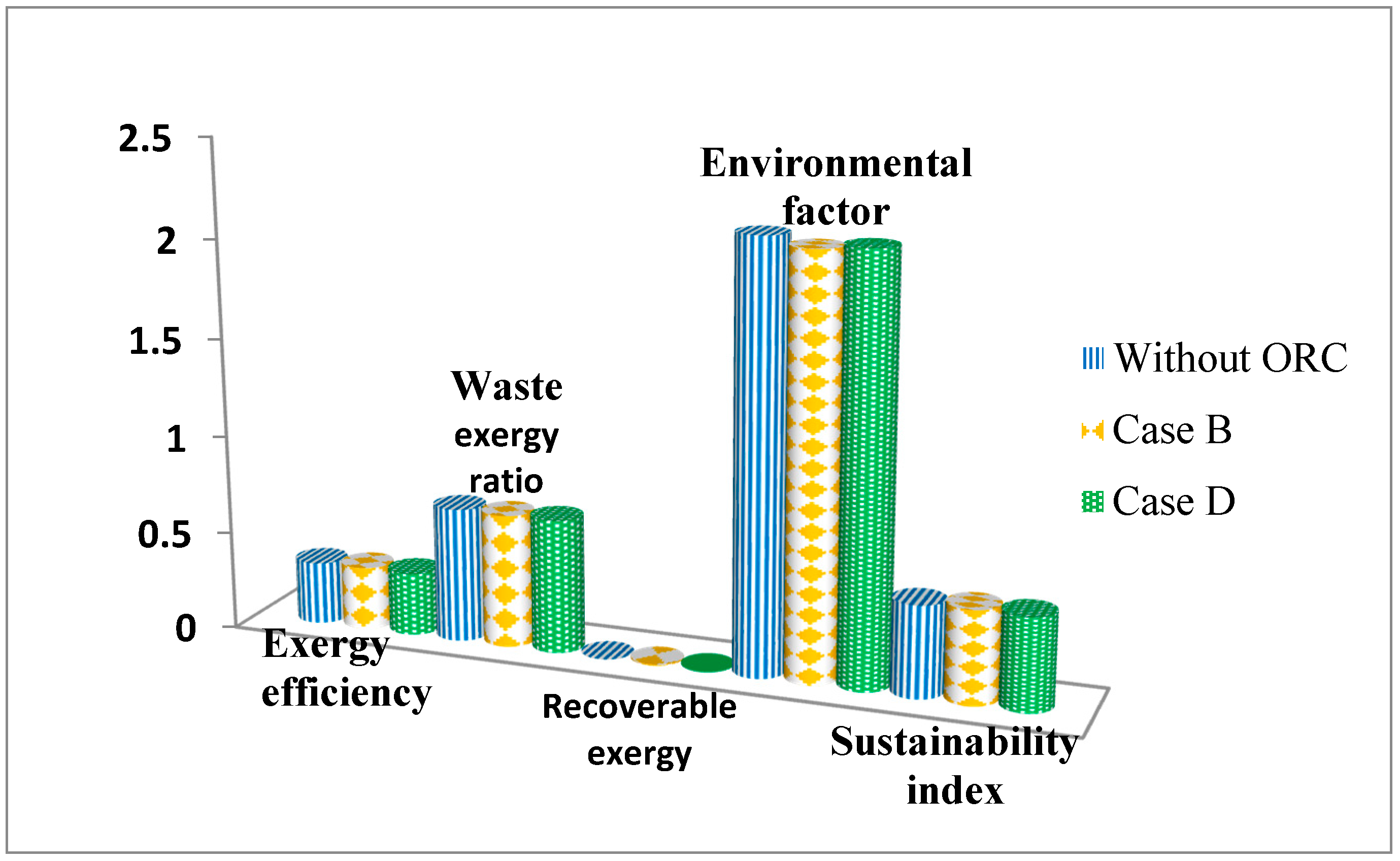
The sustainability analysis of the engine based on exergy is the most important part of this study, and it is shown in two conditions in Table 7 and Figure 17: with and without the integration of the ORC system. This analysis will only focus on case B and case D, as both of the designs show good potential in reducing the TSFC of the turbofan engine. From the numerical model of the ORC system integrated with a turbofan engine created previously, it was found that the total heat power that can be extracted from exhaust heat using ORC for cases B and D is 0.471 MW and 0.266 MW, respectively.
The exergetic sustainability index of the turbofan engine with ORC is 0.474 for case B and 0.470 for case D, which shows slight improvements of 2.16% and 1.29%, respectively, compared to the turbofan engine alone, without the integration of ORC for waste heat recovery.
Here, one can observe that, by applying an ORC system to the turbofan engine, the overall engine’s exergy efficiency is increased due to the higher thrust power produced by the engine. As a result, the exergy wasted to the environment is reduced. Compared to the turbofan engine alone, the ORC system provides an opportunity for the energy of the engine to be recovered and reused for other power needs. With this type of engine, the recoverable exergy is quite low but is still able to have a positive impact on the engine. Finally, by integrating ORC, we can reduce the engine’s environmental factor and consequently increase its index of sustainability. Here, we note that, for better practical applications, a higher value of the index of sustainability is preferable.
6. Conclusions
This work presented a detailed study of the modeling and design of an ORC system implemented in a high-bypass turbofan engine for civil aircraft. This idea came as a result of the high exergy destruction produced by the exhaust component of the engine. A model for a waste heat recovery system using ORC has been developed. The model considers the distributed modeling of the heat exchanger and a calculation of its effectiveness. Validations with previous authors’ ORC systems for industrial waste heat recovery are in good accordance with the thermal efficiency and net power output, although some deviations are identified at higher exhaust waste heat temperatures. These deviations could be, to some extent, due to the unchanged value of the inlet temperature of the working fluid assumed in our calculation.
From the four case studies of the design of this ORC system, it can be concluded that the additional heat exchanger gives advantages to the system at supercritical condition, with higher thermal efficiency and a higher net power output. Nonetheless, some precautions must be taken for supercritical cycles. These cycles must be operated at a higher operating pressure, and hence more material resistance is needed.
The effects of this ORC system concept on the engine’s fuel consumption—specifically, the effect of bleed savings—are given through the initial results of this study. For the turbofan engine considered here, the reduction in TSFC may not be too predominant. Nevertheless, it is noted that a better fuel burn value can be achieved by integrating the ORC system in a turbofan engine with the aid of a superheater at both subcritical and supercritical conditions. By considering the additional weight that may be applied to the engine, it can still reduce the fuel burn to below 7.68% for subcritical and 10.74% for supercritical conditions relative to the base cycle data.
Exergy analysis can help us to assist the rate of the improvement potential of the system and evaluate the irreversibility of the process. Meanwhile, the exergetic sustainability index has proven to be an essential method to evaluate the sustainability of a system. From this analysis, the two best cases, case B and case D, show good sustainability indices at 0.474 and 0.470, respectively. By evaluating the exergetic sustainability performance of the engine, this study shows that this type of waste heat recovery system is a relevant component and can provide significant potential to the engine, as it can increase the engine’s power and the overall engine performance. As a recommendation, it is advisable to add an ORC system to a turbofan engine as it can reduce the engine’s impact on the environment, making the engine more sustainable in future.
This study will be continued with an experimental approach in order to better evaluate the thermodynamic behavior and the performance of this new waste heat recovery system for future practical applications.
Author Contributions
Conceptualization, S.S.; methodology, S.S. and N.A.M.N.; software, S.S. and N.A.M.N.; validation, S.S. and N.A.M.N.; formal analysis, N.A.M.N.; investigation, S.S. and N.A.M.N.; resources, S.S. and N.A.M.N.; data curation, S.S. and N.A.M.N.; writing—original draft preparation, N.A.M.N.; writing—review and editing, S.S.; visualization, N.A.M.N.; supervision, S.S.; project administration, N.A.M.N.; funding acquisition, S.S. All authors have read and agreed to the published version of the manuscript.
Funding
This research was funded by a grant from University Putra Malaysia (Putra Grant-IPM: GP-IPM/2016/9498100).
Conflicts of Interest
The authors declare no conflict of interest.
Nomenclature
| A | area (m2) |
| C | heat capacity rate (kJ/(K.s)) |
| Cp | specific heat capacity (kJ/(kg.K)) |
| ex | specific exergy (kJ/kg) |
| h | enthalpy (kJ/kg) |
| IPi | exergetic improvement potential (%) |
| exergy (MW) | |
| fuel exergy (MW) | |
| HVfuel | fuel heating value (kJ/kg) |
| mass flow rate (kg/s) | |
| NTU | number of heat transfer unit (-) |
| q | heat transfer rate (kJ/s) |
| Q | total heat transfer rate (kJ/s) |
| P | pressure (kPa) |
| product exergy (MW) | |
| R | gas constant (J/(mol.K)) |
| reef | environmental effect factor (-) |
| rre | recoverable exergy (-) |
| s | entropy (kJ/kg.K) |
| T | temperature (K) |
| thrust power (kN) | |
| U | overall heat transfer coefficient (W/(m2.K)) |
| V | air speed (m/s) |
| W | power (kW) |
| X | mole fraction (-) |
| Greek letter: | |
| β | bypass ratio |
| ε | exergy efficiency |
| effectiveness of the evaporator | |
| ϴesi | exergetic sustainability index |
| ηnet | thermal efficiency |
| γ | specific heat ratio |
| Subscripts: | |
| 0 | ambient condition |
| ch | chemical |
| cond | condenser |
| hf | hot fluid |
| in | inlet |
| i | component points |
| dest | destruction |
| en | energy |
| evap | evaporator |
| ex | exergy |
| exh | exhaust |
| exp | expander/turbine |
| max | maximum |
| min | minimum |
| out | outlet |
| ph | physical |
| sup | superheater |
| Wf | working fluid |
References
- Woolley, E.; Luo, Y.; Simeone, A. Industrial waste heat recovery: A systematic approach. Sustain. Energy Technol. Assess. 2018, 29, 50–59. [Google Scholar] [CrossRef]
- Omar, A.; Saghafifar, M.; Mohammadi, K.; Alashkar, A.; Gadalla, M. A review of unconventional bottoming cycles for waste heat recovery: Part II–Applications. Energy Convers. Manag. 2019, 180, 559–583. [Google Scholar] [CrossRef]
- Xu, B.; Rathod, D.; Yebi, A.; Filipi, Z.; Onori, S.; Hoffman, M. A comprehensive review of organic rankine cycle waste heat recovery systems in heavy-duty diesel engine applications. Renew. Sustain. Energy Rev. 2019, 107, 145–170. [Google Scholar] [CrossRef]
- Shi, L.; Shu, G.; Tian, H.; Deng, S. A review of modified Organic Rankine cycles (ORCs) for internal combustion engine waste heat recovery (ICE-WHR). Renew. Sustain. Energy Rev. 2018, 92, 95–110. [Google Scholar] [CrossRef]
- Bianchi, M.; De Pascale, A. Bottoming cycles for electric energy generation: Parametric investigation of available and innovative solutions for the exploitation of low and medium temperature heat sources. Appl. Energy 2011, 88, 1500–1509. [Google Scholar] [CrossRef]
- Parmenter, K.; Fouche, E.; Ehrhard, R. Tech Review: Industrial Heat Pumps for Waste Heat Recovery; Industrial Technology Application Service; Global Energy Partners: Houston, TX, USA, 2007. [Google Scholar]
- Glover, S.; Douglas, R.; Glover, L.; McCullough, G. Preliminary analysis of organic Rankine cycles to improve vehicle efficiency. Proc. Inst. Mech. Eng. Part D 2014, 228, 1142–1153. [Google Scholar] [CrossRef]
- Gao, H.; Liu, C.; He, C.; Xu, X.; Wu, S.; Li, Y. Performance Analysis and Working Fluid Selection of a Supercritical Organic Rankine Cycle for Low Grade Waste Heat Recovery. Energies 2012, 5, 3233–3247. [Google Scholar] [CrossRef]
- Shu, G.; Yu, G.; Tian, H.; Wei, H.; Liang, X. A Multi-Approach Evaluation System (MA-ES) of Organic Rankine Cycles (ORC) used in waste heat utilization. Appl. Energy 2014, 132, 325–338. [Google Scholar] [CrossRef]
- Karellasa, S.; Schusterb, A.; Leontaritis, A.-D. Influence of supercritical ORC parameters on plate heat exchanger design. Appl. Therm. Eng. 2012, 33–34, 70–76. [Google Scholar] [CrossRef]
- Chowdhury, J.I.; Nguyen, B.K.; Thornhill, D. Investigation of waste heat recovery system at supercritical conditions with vehicle drive cycles. J. Mech. Sci. Technol. 2017, 31, 923–936. [Google Scholar] [CrossRef]
- Daniel, R.M. Assessment of the Integration of an Organic Rankine Cycle for Waste Heat Recovery from Bleed Air for Implementation on Board an Aircraft. Master’s Thesis, Durham University, Durham, UK, 2018. [Google Scholar]
- Boz, B.; Diez, A. Comparative study of subcritical and supercritical ORC applications for exhaust waste heat recovery. Int. J. Energy Power Eng. 2018, 12, 119–127. [Google Scholar]
- Yagli, H.; Koc, Y.; Koc, A.; Gorgulu, A.; Tandiroglu, A. Parametric optimization and exergetic analysis comparison of subcritical and supercritical ORC for biogas fueled combined heat and power (CHP) engine exhaust gas waste heat. Energy 2016, 111, 923–932. [Google Scholar] [CrossRef]
- Gao, T.; Liu, C. Off-design performances of subcritical and supercritical organic Rankine cycles in geothermal power systems under an optimal control strategy. Energies 2017, 10, 1185. [Google Scholar]
- Yang, M.H.; Yeh, R.H. Thermodynamic and economic performances optimization of an organic Rankine cycle system utilizing exhaust gas of a large marine diesel engine. Appl. Energy 2015, 149, 1–12. [Google Scholar] [CrossRef]
- Douvartzides, S.; Karmalis, I. Working fluid selection for the Organic Rankine Cycle (ORC) exhaust heat recovery of an internal combustion engine power plant. IOP Conf. Ser. 2016, 161, 012087. [Google Scholar] [CrossRef] [Green Version]
- Perullo, C.A.; Mavris, D.N.; Fonseca, E. An integrated assessment of an organic Rankine cycle concept for use in onboard aircraft power generation. In Proceedings of the ASME Turbo Expo 2013: Turbine Technical Conference and Exposition, San Antonio, TX, USA, 3–7 June 2013. [Google Scholar]
- De Servi, C.M.; Azzini, L.; Pini, M.; Gangoli Rao, A.; Colonna, P. Exploratory assessment of a combined-cycle engine concept for aircraft propulsion. In Proceedings of the 1st Global Power and Propulsion Forum, GPPF-2017-78, Zurich, Switzerland, 16–18 January 2017. [Google Scholar]
- Petit, O.; Xisto, C.; Zhao, X.; Grönstedt, T. An outlook for radical aero-engine intercooler concepts. In Proceedings of the ASME Turbo Expo 2016: Turbomachinery Technical Conference and Exposition, American Society of Mechanical Engineers Digital Collection, GT2016-57920, Seoul, Korea, 13–17 June 2016. [Google Scholar]
- Sohret, Y.; Ekici, S.; Altuntas, O.; Hepbasli, A.; Karakoc, T.H. Exergy as a useful tool for the performance assessment of aircraft gas turbine engines: A key review. Prog. Aerosp. Sci. 2016, 83, 57–69. [Google Scholar] [CrossRef]
- Sohret, Y.; Dinc, A.; Karakoc, T.H. Exergy analysis of a turbofan engine for an unmanned aerial vehicle during a surveillance mission. Energy 2015, 93, 716–729. [Google Scholar] [CrossRef]
- Turgut, E.T.; Karakoc, T.H.; Hepbasli, A.; Rosen, M.A. Exergy analysis of a turbofan aircraft engine. Int. J. Exergy 2009, 6, 181–199. [Google Scholar] [CrossRef]
- Tona, C.; Raviolo, P.A.; Pellegrin, L.F.; Oliveira Junior, S. Exergy and thermoeconomic analysis of a turbofan engine during a typical commercial flight. Energy 2010, 35, 952–959. [Google Scholar] [CrossRef]
- Turan, O. An exergy way to quantify sustainability metrics for a high bypass turbofan engine. Energy 2015, 86, 722–736. [Google Scholar] [CrossRef]
- Turan, O.; Aydin, H. Exergy based sustainability analysis of a low bypass turbofan engine: A case study for JT8D. Energy Procedia 2016, 95, 499–506. [Google Scholar] [CrossRef] [Green Version]
- Aydin, H.; Turan, O.; Karakoc, T.H. Exergetic sustainability indicators as a tool in commercial aircraft: A case study for a turbofan engine. Int. J. Green Energy 2014, 12, 28–40. [Google Scholar] [CrossRef]
- Saadon, S.; Mohd Redzuan, M.S. Sustainability assessment of turbofan engine with mixed exhaust through exergetic approach. IOP Conf. Ser. 2017, 270, 012012. [Google Scholar] [CrossRef] [Green Version]
- Saadon, S.; Talib, A.R.A. An analytical study on the performance of the organic Rankine cycle for turbofan engine exhaust heat recovery. IOP Conf. Ser. 2016, 152, 012011. [Google Scholar] [CrossRef]
- Saadon, S. Computational modeling of an Organic Rankine Cycle (ORC) waste heat recovery system for an aircraft engine. Matec Web Conf. 2018, 151, 02001. [Google Scholar] [CrossRef] [Green Version]
- Sun, J.; Li, W. Operation optimization of an Organic Rankine Cycle (ORC) heat recovery power plant. Appl. Therm. Eng. 2011, 31, 2032–2041. [Google Scholar] [CrossRef]
- Chowdhury, J.I.; Nguyen, B.K.; Thornhill, D. Modelling of evaporator in waste heat recovery system using finite volume method and fuzzy technique. Energies 2015, 8, 14078–14097. [Google Scholar] [CrossRef] [Green Version]
- Saadon, S.; Gaillard, L.; Giroux-Julien, S.; Menezo, C. Simulation study of a naturally ventilated building integrated photovoltaic (BIPV) envelope. Energy Procedia 2015, 78, 2004–2009. [Google Scholar] [CrossRef]
- Song, F.; Zhao, B.; Yang, X.; Jiang, Y.; Gopal, V.; Dobbs, G.; Sahm, M. A new approach on zonal modeling of indoor environment with mechanical ventilation. Build. Environ. 2008, 43, 278–286. [Google Scholar] [CrossRef]
- Nasir, N.A.M.; Saadon, S.; Abu Talib, A.R. Performance analysis of an Organic Rankine Cycle system with superheater utilizing exhaust gas of a turbofan engine. Int. J. of Eng. and Technology 2018, 7, 120–124. [Google Scholar] [CrossRef]
- Song, J.; Gu, C.W.; Ren, X. Parametric design and off-design analysis of Organic Rankine Cycle (ORC). Energy Convers. Manag. 2016, 112, 157–165. [Google Scholar] [CrossRef]
- Song, J.; Song, Y.; Gu, C.W. Thermodynamic analysis and performance optimization of an Organic Rankine Cycle (ORC) waste heat recovery system for marine diesel engines. Energy 2015, 82, 976–985. [Google Scholar] [CrossRef]
- Song, J.; Gu, C.W. Analysis of ORC (Organic Rankine Cycle) systems with pure hydrocarbons and mixtures of hydrocarbon and retardant for engine waste heat recovery. Appl. Therm. Eng. 2015, 89, 693–702. [Google Scholar] [CrossRef]
- Javanshir, A.; Sarunac, N.; Razzaghpanah, Z. Thermodynamic Analysis of ORC and Its Application for Waste Heat Recovery. Sustainability 2017, 9, 1974. [Google Scholar] [CrossRef] [Green Version]
- Guo, C.; Du, X.; Yang, L.; Yang, Y. Performance analysis of organic Rankine cycle based on location of heat transfer pinch point in evaporator. Appl. Therm. Eng. 2014, 62, 176–186. [Google Scholar] [CrossRef]
- Bejan, A.; Moran, M.J.; Tsatsaronis, G. Thermal Design and Optimization; Wiley: New York, NY, USA, 1996. [Google Scholar]
- Szargut, J.M.; Morris, D.R.; Steward, F.R. Exergy Analysis of Thermal, Chemical and Metallurgical Processes; Hemisph: New York, NY, USA, 1988. [Google Scholar]
- Dincer, I. Environmental and sustainability aspects of hydrogen and fuel cell systems. Int. J. Energy Res. 2007, 31, 29–55. [Google Scholar] [CrossRef]
- Aydin, H.; Turan, O.; Karakoc, T.H.; Midilli, A. Sustainability assessment of PW6000 turbofan engine: An exergetic approach. Int. J. Exergy 2014, 4, 388–412. [Google Scholar] [CrossRef]
- Xiang, J.Y.; Cali, M.; Santarelli, M. Calculation for physical and chemical exergy of flows in systems elaborating mixed-phase flows and a case study in an IRSOFC plant. Int. J. Energy Res. 2004, 28, 101–115. [Google Scholar] [CrossRef]
- Tsatsaronis, G. Definitions and nomenclature in exergy analysis and exergoeconomics. Energy 2007, 32, 249–253. [Google Scholar] [CrossRef]
- Van Gool, W. Energy policy fairy tales and factuality. In Innovation and Technology-Strategies and Policies; Kluwer: Dordrecht, The Netherlands, 1997; pp. 93–105. [Google Scholar]
- Ozdemir, K.; Hepbasli, A.; Eskin, N. Exergoeconomic analysis of a fluidized-bed coal combustor (FBCC) steam power plant. App. Therm. Eng. 2010, 30, 1621–1631. [Google Scholar] [CrossRef]
- Balli, O.; Hepbasli, A. Exergoeconomic, sustainability and environmental damage cost analyses of T56 turboprop engine. Energy 2014, 64, 582–600. [Google Scholar] [CrossRef]
- Aydin, H.; Turan, O.; Karakoc, T.H.; Midilli, A. Exergo-sustainability indicators of a turboprop aircraft for the phases of a flight. Energy 2013, 58, 550–560. [Google Scholar] [CrossRef]
- Midilli, A.; Dincer, I. Development of some exergetic parameters for PEM fuel cells for measuring environmental impact and sustainability. Int. J. Hydrog. Energy 2009, 34, 3858–3872. [Google Scholar] [CrossRef]
- Midilli, A.; Dincer, I. Effects of some micro-level exergetic parameters of a PEMFC on the environment and sustainability. Int. J. Glob. Warm. 2010, 2, 65–80. [Google Scholar] [CrossRef]
- Midilli, A.; Kucuk, H.; Dincer, I. Environmental and sustainability aspects of a recirculating aquaculture system. Environ. Prog. Sustain. 2012, 31, 604–611. [Google Scholar] [CrossRef]
Figure 1.
Schematic diagram of a basic Organic Rankine Cycle (ORC) system.
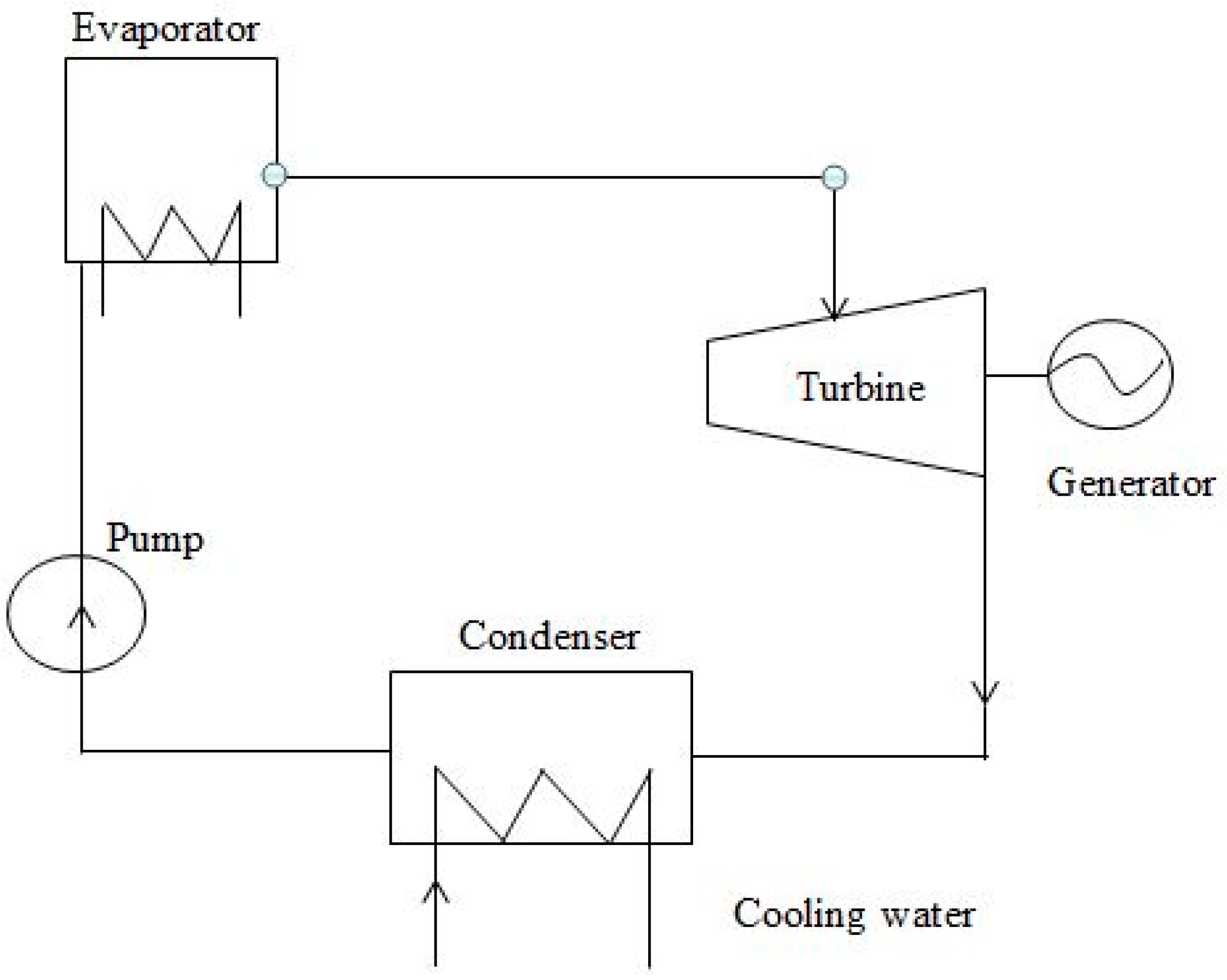
Figure 2.
The evaporator discrete segments [35].
Figure 2.
The evaporator discrete segments [35].

Figure 3.
Procedure of performance modeling of ORC system [35].
Figure 3.
Procedure of performance modeling of ORC system [35].
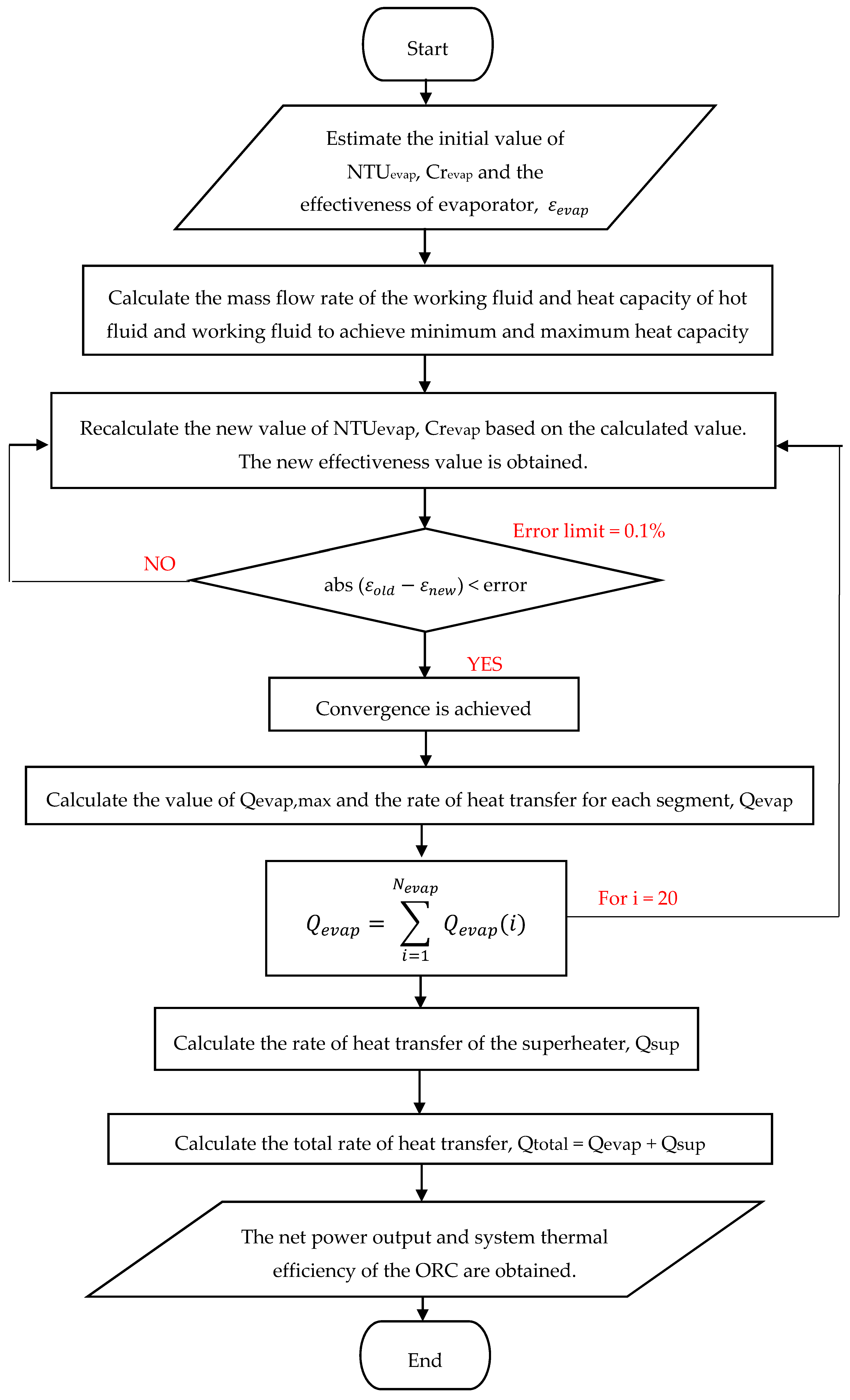
Figure 4.
Net power output vs. exhaust heat temperature.

Figure 5.
System thermal efficiency vs. exhaust heat temperature.
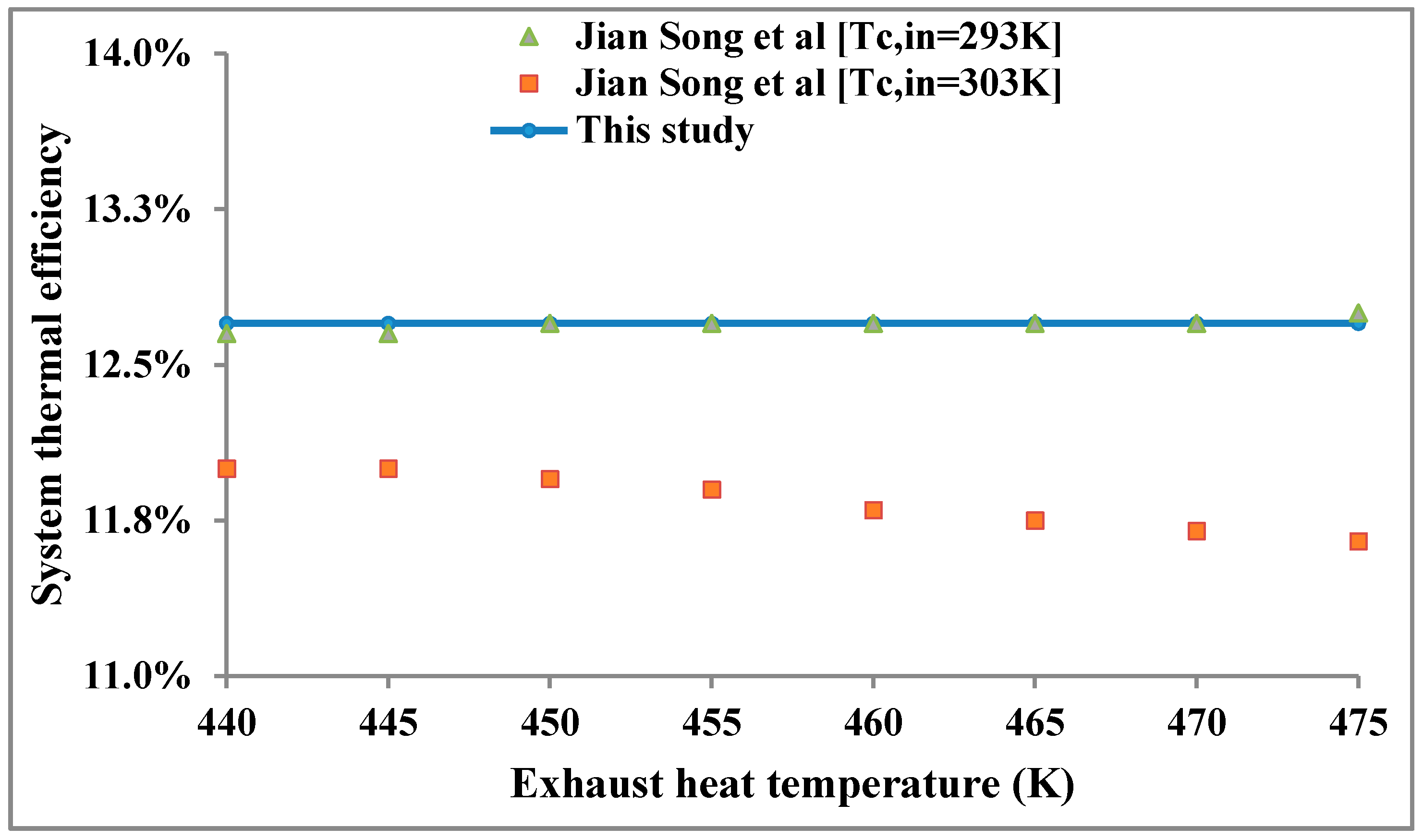
Figure 6.
Schematic diagram for case A and case C.
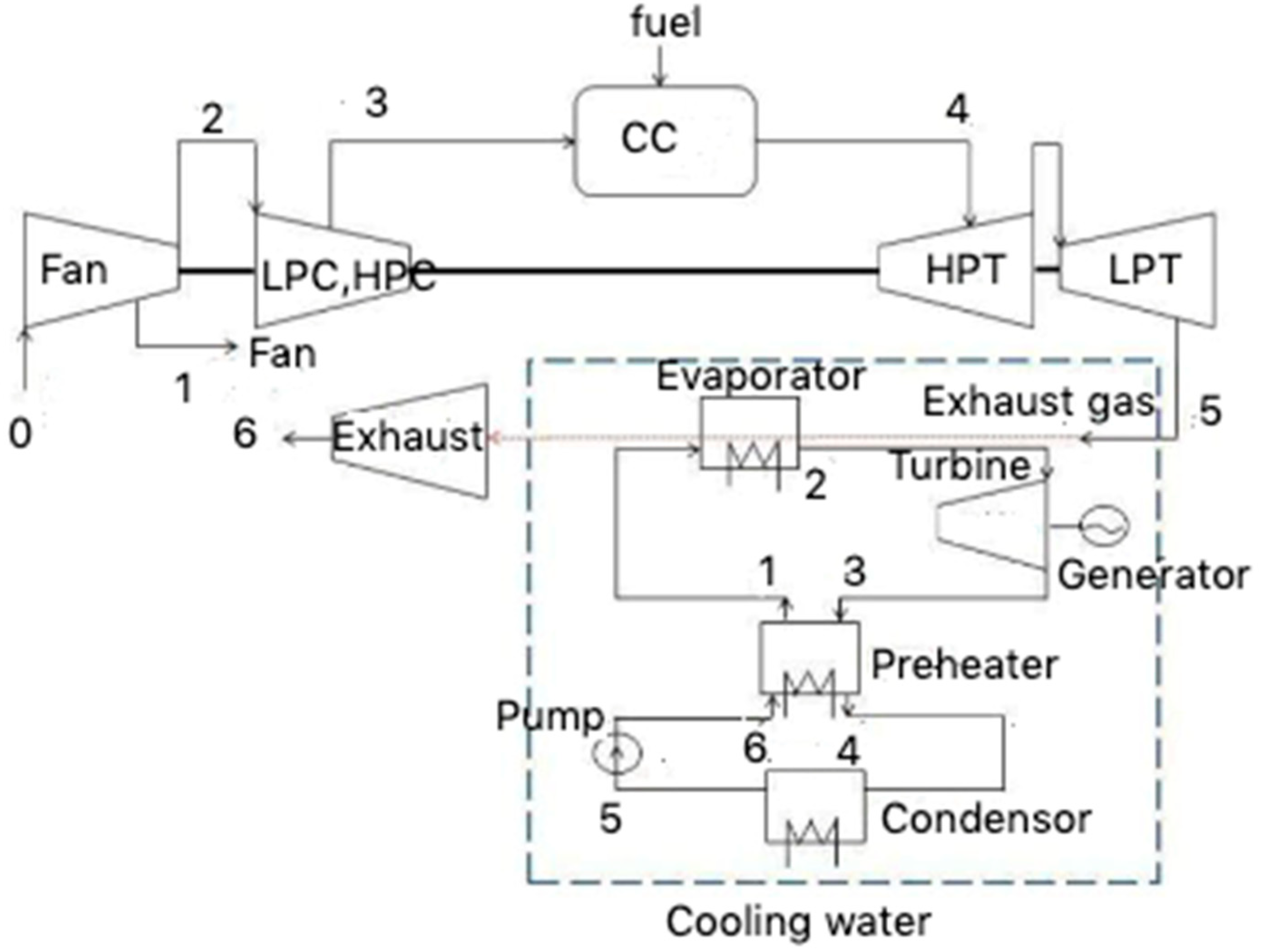
Figure 7.
Schematic diagram for case B and case D [35].
Figure 7.
Schematic diagram for case B and case D [35].

Figure 8.
(a) T–s diagram for case A and (b) T–s diagram for case B. (c) T–s diagram for case C and (d) T–s diagram for case D.
Figure 8.
(a) T–s diagram for case A and (b) T–s diagram for case B. (c) T–s diagram for case C and (d) T–s diagram for case D.


Figure 9.
Net power output vs. exhaust heat temperature.

Figure 10.
System thermal efficiency with exhaust waste heat temperature.
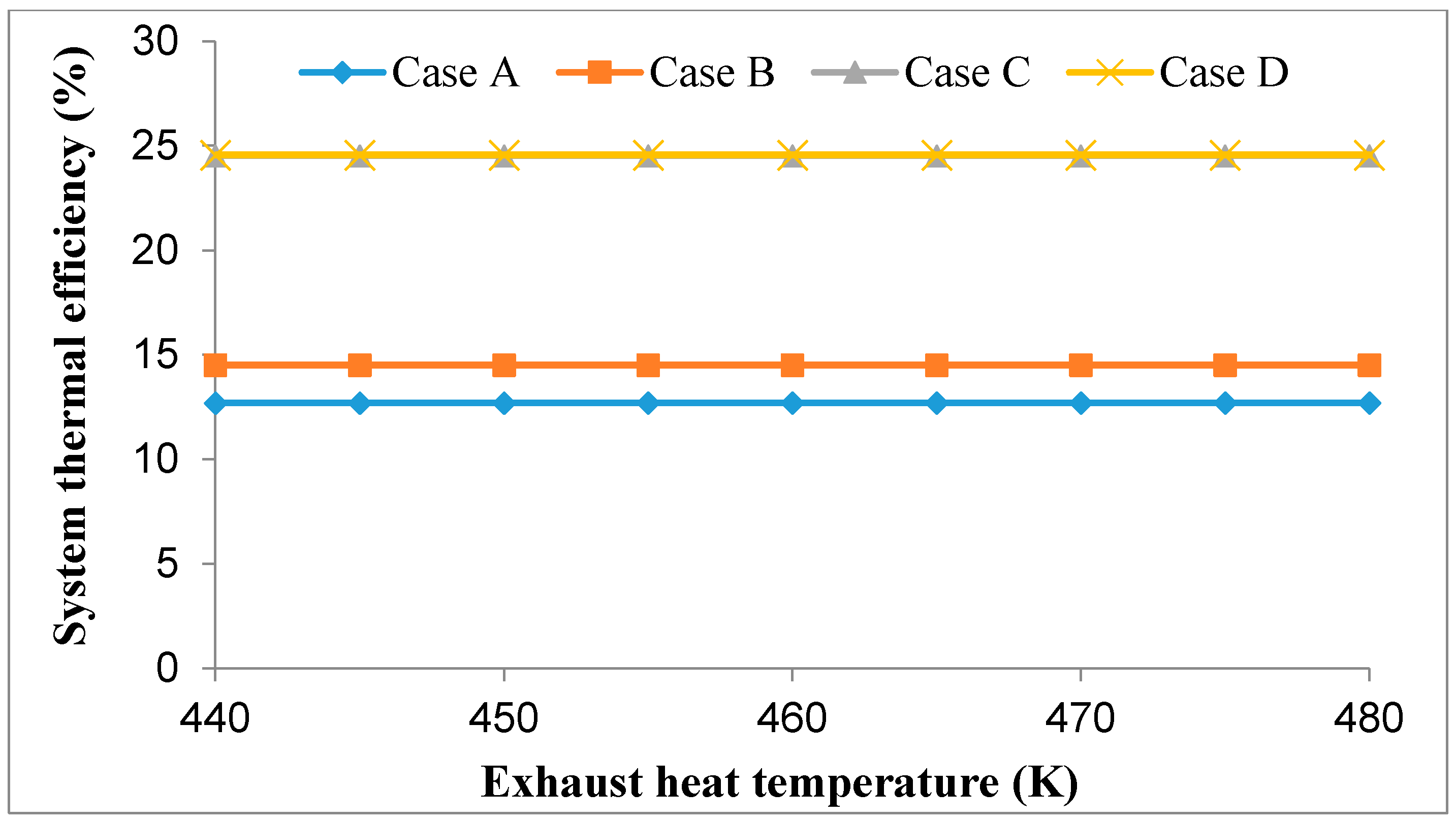
Figure 11.
Mass flow rate according to exhaust waste heat temperature.
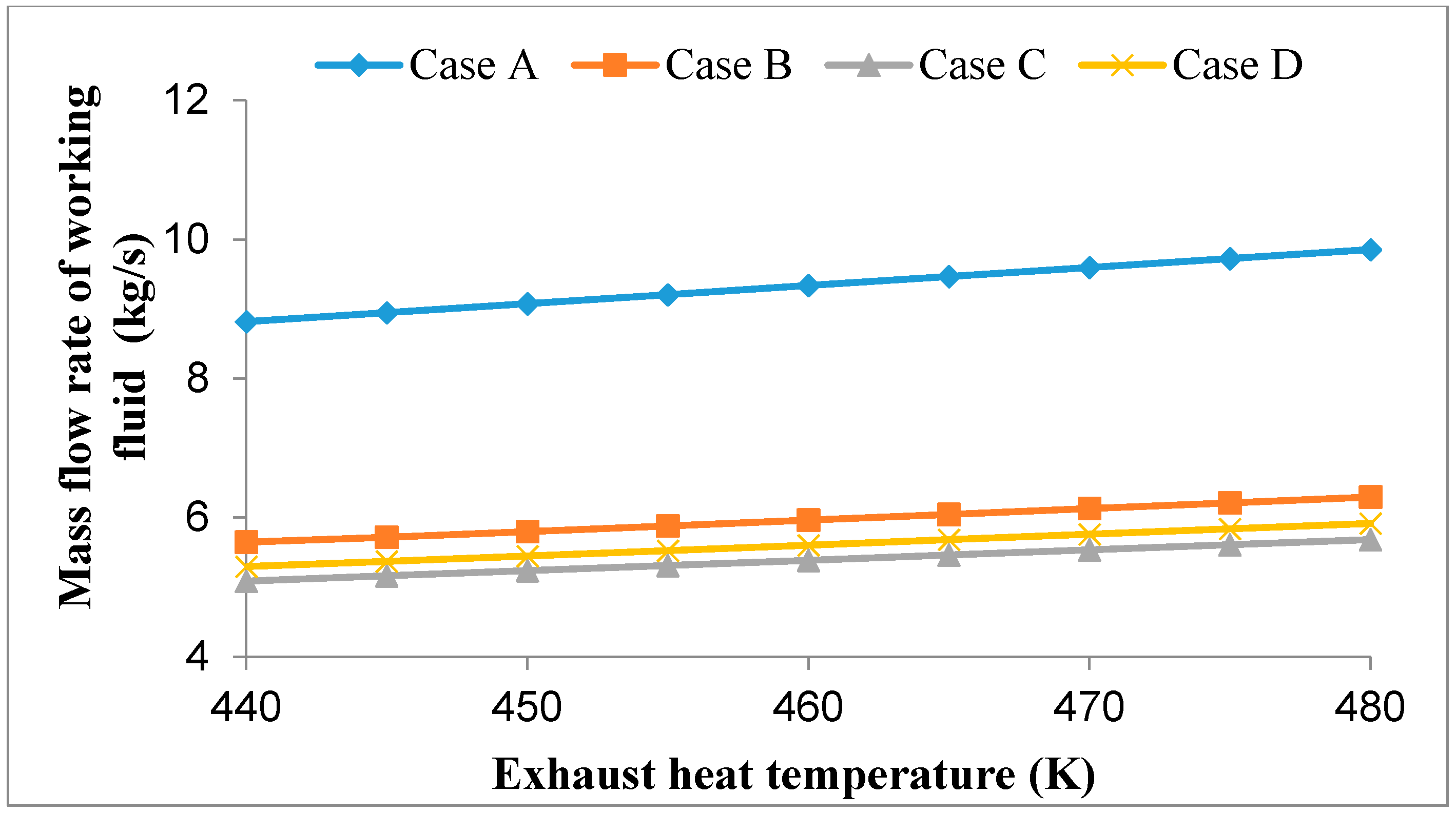
Figure 12.
Graph of Thrust-Specific Fuel Consumption (TSFC) against thrust.
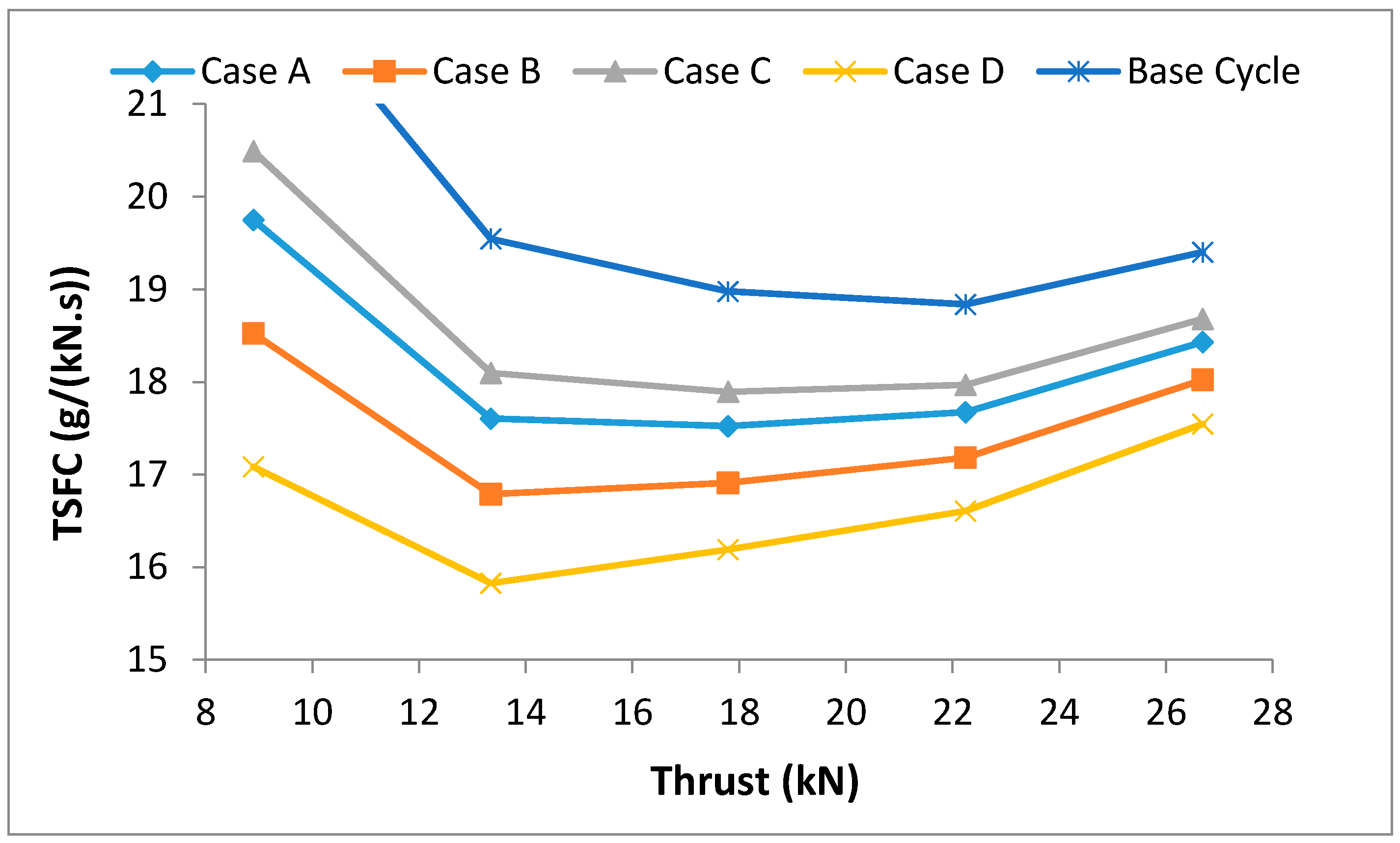
Figure 13.
The values of fuel burn relative to the base cycle.
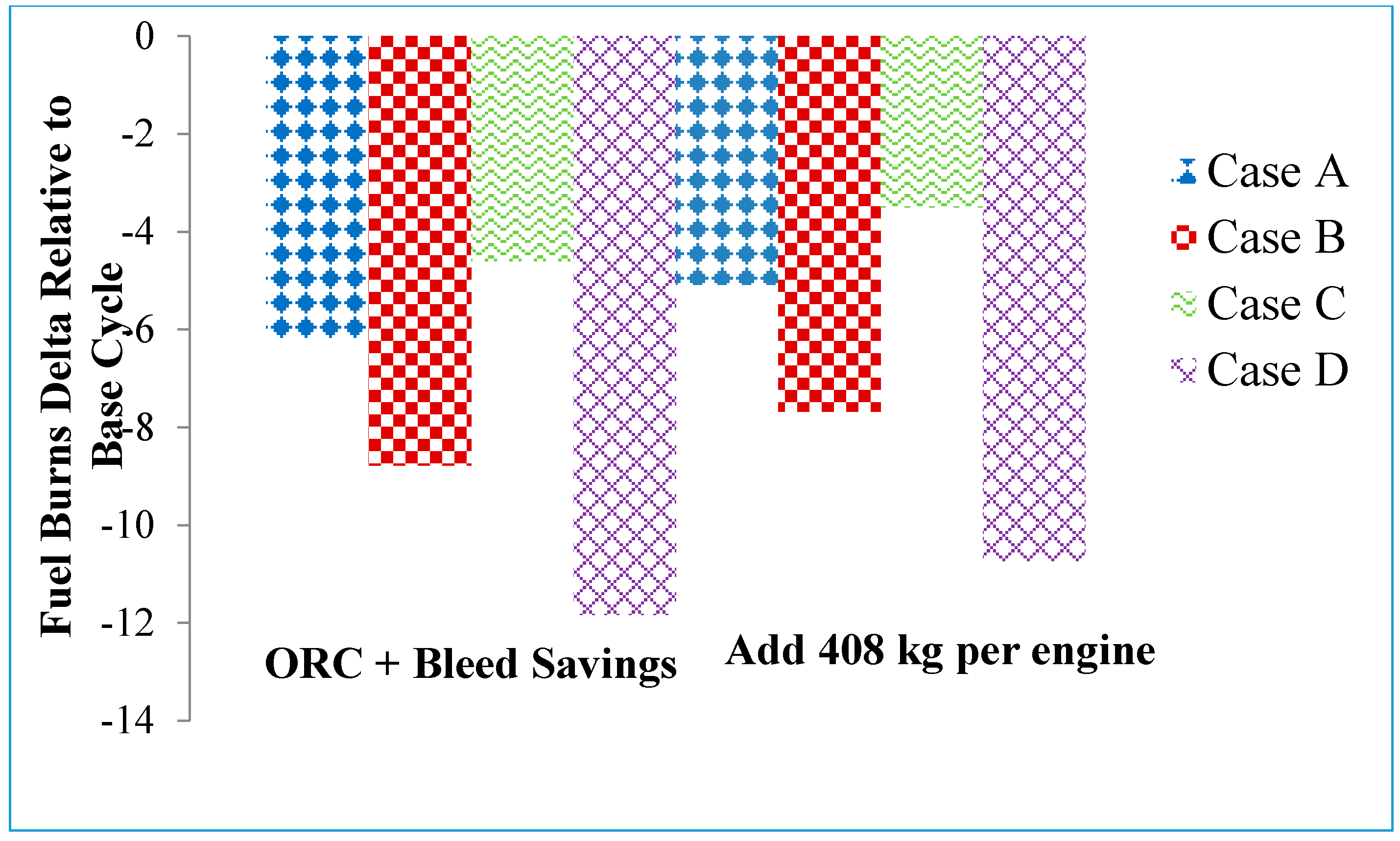
Figure 14.
Exergy efficiency of the engine components.
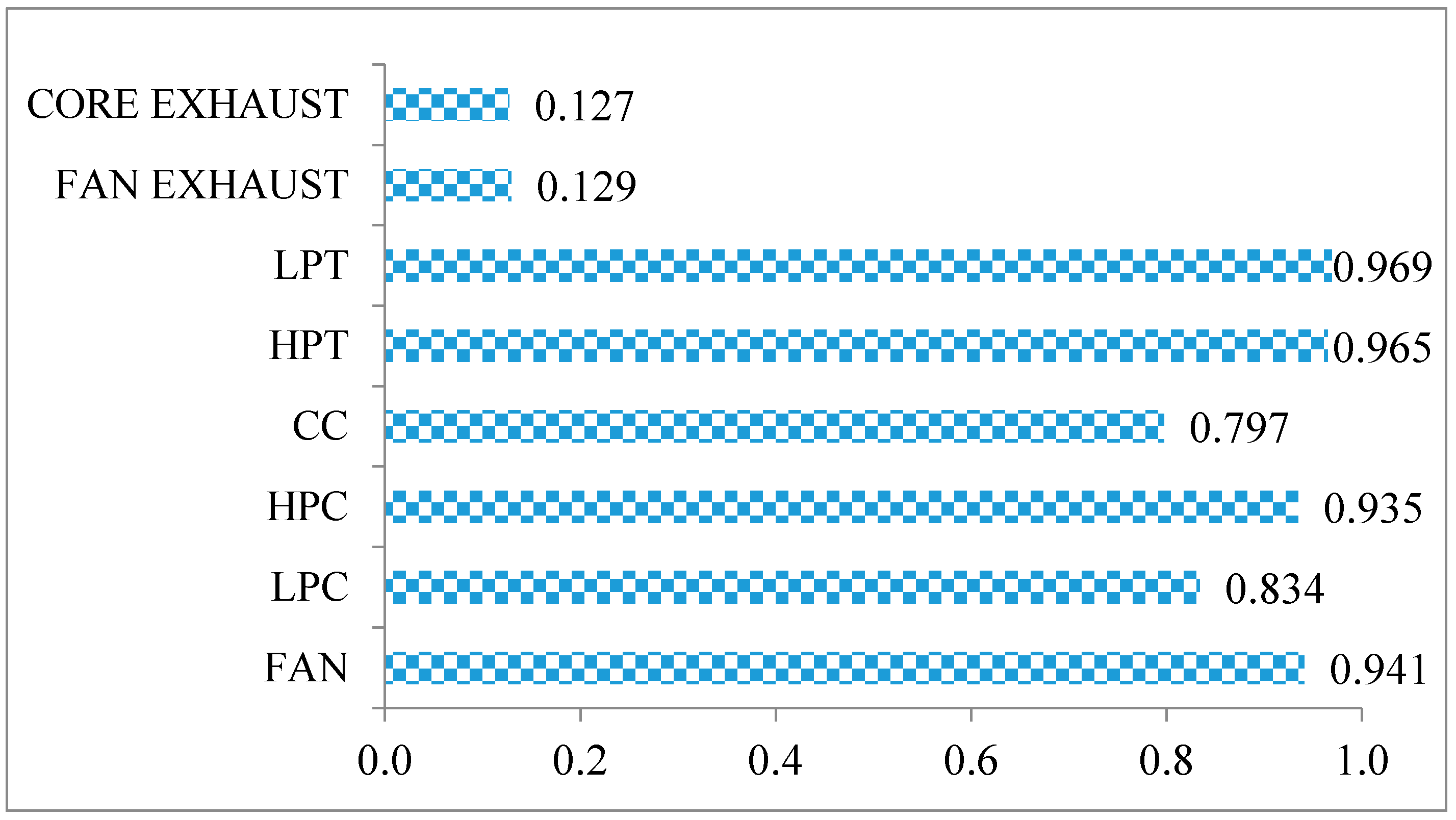
Figure 15.
Exergy destruction rates of each component.
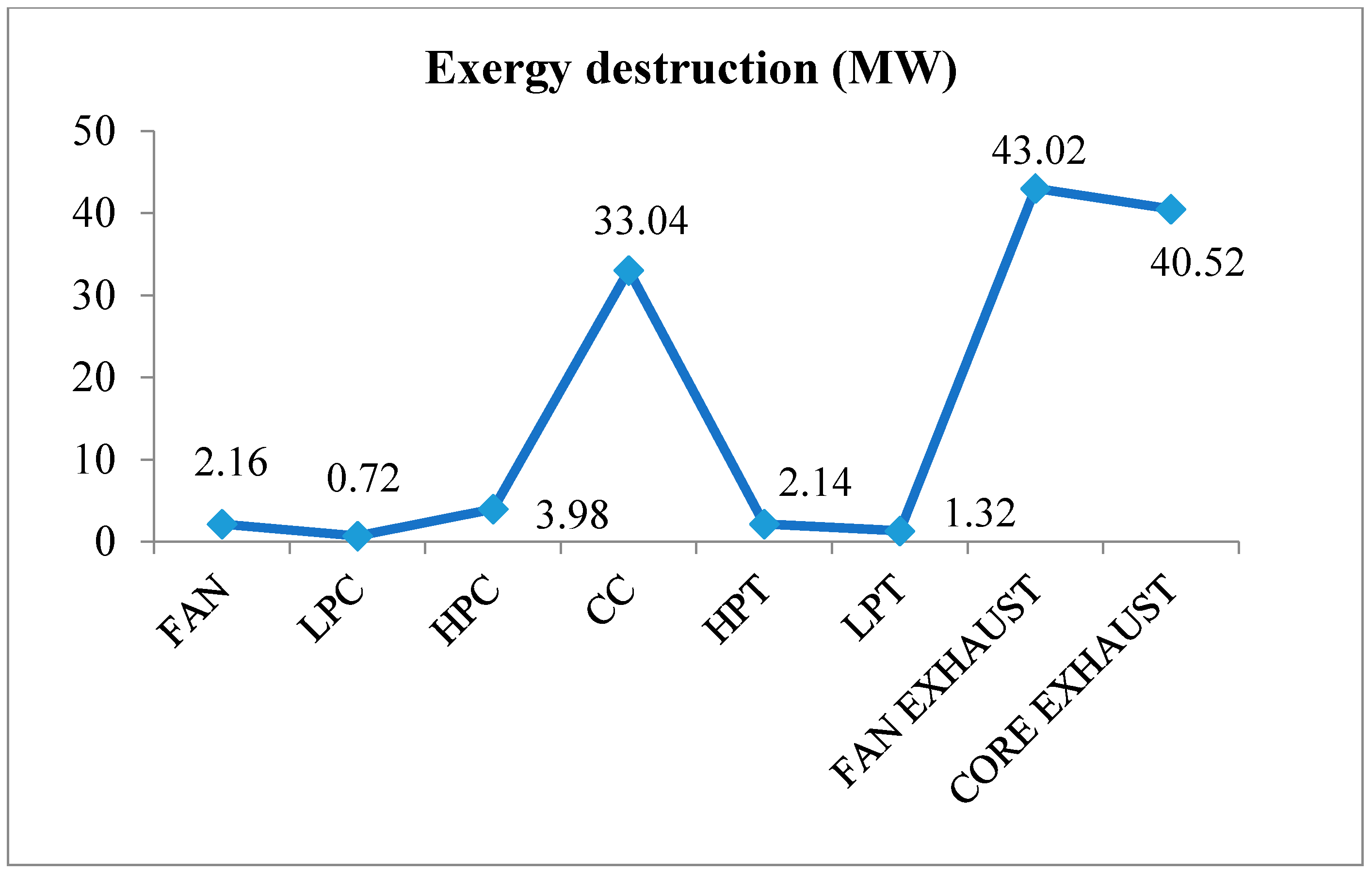
Figure 16.
The potential improvement rate based on exergy.

Figure 17.
Exergetic sustainability factor of the engine with and without ORC system.

Table 1.
Values of ORC system used for validation.
| Parameters | Value |
|---|---|
| R123 mass flow rate | 21.2 kg/s |
| Exhaust heat mass flow rate | 20 kg/s |
| The inlet temperature of the exhaust heat | 440–480 K |
| The condensation temperature | 303–319 K |
| The inlet cooling water temperature | 288–298 K |
| The efficiency of the turbine | 0.6 |
| The efficiency of the pump | 0.8 |
Table 2.
Parameters used for case A and case C.
| Parameters | Value of Case A | Value of Case C |
|---|---|---|
| The evaporation temperature | 350 K | - |
| The working fluid at turbine inlet temperature | 350 K | 430 K |
Table 3.
Parameters used for case B and case D.
| Parameters | Value of Case B | Value of Case D |
|---|---|---|
| The working fluid temperature at superheater inlet | 350 K | 428 K |
| The evaporation temperature | 350 K | - |
| The working fluid at turbine inlet temperature | 393 K | 440 K |
Table 4.
ORC system parameters when connected a turbofan engine [18].
Table 4.
ORC system parameters when connected a turbofan engine [18].
| Parameters | Value |
|---|---|
| R245fa mass flow rate | 3.84 kg/s |
| Evaporator surface area | 23.72 m2 |
| Evaporator heat transfer rate | 1105 kW |
| The temperature of exhaust heat | 843 K |
| R245fa inlet temperature | 282 K |
| R245fa outlet temperature | 393 K |
| Turbine inlet temperature | 392 K |
| Turbine inlet pressure | 1.21 MPa |
| Turbine outlet pressure | 0.55 MPa |
| The efficiency of pump | 0.70 |
| The efficiency of turbine | 0.87 |
Table 5.
Standard chemical exergy of chemical constituents [42].
Table 5.
Standard chemical exergy of chemical constituents [42].
| Air’s Chemical Composition | Model, kJ/kmol |
|---|---|
| Carbon Dioxide (CO2) | 14,175 |
| Water (H2O) | 8635 |
| Oxygen (O2) | 3950 |
| Nitrogen (N2) | 640 |
Table 6.
Design parameters for exergy analysis of sea level data.
| Parameters | Value |
|---|---|
| P0 (kPa) | 101.3 |
| T0 (K) | 306.5 |
| s0 (kJ/kg.K) | 6.9 |
| h0 (kJ/kg) | 308.4 |
Table 7.
Exergetic sustainability factor of the engine with and without ORC.
| Component | Without ORC | Case B | Percentage of Improvement (%) | Case D | Percentage of Improvement (%) |
|---|---|---|---|---|---|
| Exergy efficiency | 0.317 | 0.322 | 1.58 | 0.320 | 0.95 |
| Waste exergy | 0.683 | 0.678 | 0.73 | 0.680 | 0.44 |
| Recoverable exergy | 0 | 0.005 | - | 0.003 | - |
| Environmental factor | 2.154 | 2.108 | 2.14 | 2.123 | 1.44 |
| Sustainability index | 0.464 | 0.474 | 2.16 | 0.470 | 1.29 |
© 2020 by the authors. Licensee MDPI, Basel, Switzerland. This article is an open access article distributed under the terms and conditions of the Creative Commons Attribution (CC BY) license (http://creativecommons.org/licenses/by/4.0/).
Share and Cite
MDPI and ACS Style
Saadon, S.; Mohd Nasir, N.A. Performance and Sustainability Analysis of an Organic Rankine Cycle System in Subcritical and Supercritical Conditions for Waste Heat Recovery. Energies 2020, 13, 3035. https://doi.org/10.3390/en13123035
AMA Style
Saadon S, Mohd Nasir NA. Performance and Sustainability Analysis of an Organic Rankine Cycle System in Subcritical and Supercritical Conditions for Waste Heat Recovery. Energies. 2020; 13(12):3035. https://doi.org/10.3390/en13123035
Chicago/Turabian StyleSaadon, Syamimi, and Nur Athirah Mohd Nasir. 2020. "Performance and Sustainability Analysis of an Organic Rankine Cycle System in Subcritical and Supercritical Conditions for Waste Heat Recovery" Energies 13, no. 12: 3035. https://doi.org/10.3390/en13123035
Note that from the first issue of 2016, this journal uses article numbers instead of page numbers. See further details here.