Review

Thermal Storage Using Metallic Phase Change Materials for Bus Heating—State of the Art of Electric Buses and Requirements for the Storage System

German Aero Space Center, Institute of Vehicle Concepts, 70569 Stuttgart, Germany
*
Author to whom correspondence should be addressed.
Energies 2020, 13(11), 3023; https://doi.org/10.3390/en13113023
Submission received: 12 March 2020 / Revised: 23 April 2020 / Accepted: 27 April 2020 / Published: 11 June 2020
(This article belongs to the Special Issue Energy Storage Systems for Electric Vehicles)

Abstract

:
Battery-powered electric buses currently face the challenges of high cost and limited range, especially in winter conditions, where interior heating is required. To face both challenges, the use of thermal energy storage based on metallic phase change materials for interior heating, also called thermal high-performance storage, is considered. By replacing the battery capacity through such an energy storage system, which is potentially lighter, smaller, and cheaper than the batteries used in buses, an overall reduction in cost and an increase of range in winter conditions could be reached. Since the use of thermal high-performance storage as a heating system in a battery-powered electric bus is a new approach, the requirements for such a system first need to be known to be able to proceed with further steps. To find these requirements, a review of the relevant state of the art of battery-powered electric buses, with a focus on heating systems, was done. Other relevant aspects were vehicle types, electric architecture, battery systems, and charging strategies. With the help of this review, requirements for thermal high-performance storage as a heating system for a battery-powered electric bus were produced. Categories for these requirements were the thermal capacity and performance, long-term stability, mass and volume, cost, electric connection, thermal connection, efficiency, maintenance, safety, adjustment, and ecology.

1. Introduction

The latest reports on global warming show a significant increase in the worldwide average surface temperatures on earth compared to the pre-industrial era. Since this effect is related mainly to the rise of human CO2 emissions from burning fossil fuels, such as coal, oil, or gas, reducing the use of them seems to be a way to restrict global warming.
In terms of public transport, buses using diesel fuel are the dominant vehicle category. Out of the 80,519 buses registered in Germany, a total of 78,472 (a relative portion of 97.5%) are diesel-fueled buses, amounting to a large majority. Toward the aim of protecting the climate and reducing local emissions like NOx or noise, replacing diesel-fueled buses with battery-powered electric buses could have positive effects. However, the number of fully electric buses, which is 228 and therefore contributing to an amount of 0.28% to the total amount of buses, is currently insignificant [1].
Since public transport is often uneconomical and has to be subsidized, low costs for the acquisition, energy consumption, and maintenance of public transport are highly relevant. However, prices for electric buses are currently roughly double that of diesel buses. Additionally, high investments in the charging infrastructure are necessary. Besides the costs, the range of electric buses is limiting the application possibilities in public transport, since not every tour can be served if the buses cannot be readily charged. Since the interior heating capacity can exceed the necessary power for traction in low ambient temperatures, the range issue becomes even worse if interior heating is required on low ambient temperatures and heating systems using electric energy are used. A further description of these challenges is given in Section 2.4. As an example, the dependence of the required heating capacity on the ambient temperature of a 12 m city bus is shown in Figure 1. By way of comparison, the energy demand for the traction of a 12 m city bus is in the magnitude of 1.1 kWh/km. [2]
Since the prices for batteries are high (up to approx. 930 €/kWh, see Section 2.1.3) and the energy densities are limited (up to 160–180 Wh/kg, see Section 2.1.3), using a high battery capacity is part of the two described issues and currently low usage of electric busses. Therefore, replacing the battery capacity with a more lightweight and more affordable energy storage method could be a solution to solve this problem.
As mentioned, interior heating has a huge contribution to the energy consumption of an electric bus in winter conditions. To overcome the problem of the high cost and limited range in winter conditions, the use of thermal high-performance storage (THS) made of metallic phase change materials (mPCM) could be a potential solution, as already described in past publications. The idea is to charge the THS and the battery simultaneously, where the energy stored in the THS is provided to the cabin while driving. By doing so, no electric energy from the battery has to be used and therefore the range can be increased. Furthermore, no battery capacity needs to be available for heating and therefore can be designated only for driving. Metallic phase change materials are selected as the main choice since they offer high thermal conductivities at high energy densities and low cost. The high thermal conductivity enables the potential for fast charging, which can be very relevant. The maximum storage temperatures are intended to be 600–700 °C [3,4].
Since the application of THS as a heating unit in electric buses is a new approach, the requirements for such a system must first be known to be able to proceed with further steps, such as conceptual designing or experimental investigation. Therefore, this review aimed toward finding these requirements. To do so, first, the relevant state of the art of battery-powered electric buses is shown. The relevant aspects are vehicle types, electric architecture, battery systems, charging strategies, and especially heating systems. With the help of this knowledge, the requirements for THS are established and discussed.

2. State of the Art of Electric Buses

2.1. Electric Buses in General

2.1.1. Common Vehicle Types

Buses can be generally divided into different categories, which mainly comes from their use case or their size. In terms of their use case, categories are airport buses, city buses, regional buses, and coaches for traveling. The main differences between these kinds of buses are, e.g., the range, comfort for passengers, door sizes, engine power, and the type of construction (low floor or high floor) [5,6,7,8]. In terms of size, buses can be categorized into small buses (<6 m), mini-buses (6–8 m), midi-buses (8–10.6 m), standard buses with two axles, (10.6–13.5 m), double-decker buses (10–11 m), standard buses with three axles (13.5–15 m), articulated buses (17.5–19 m), and double-articulated buses (21–26.2 m) [9]. Since battery-powered electric buses have mainly been used as city buses, the focus will be put on this category. A detailed overview of battery-powered electric buses that are currently available on the market is given by Faltenbacher et al. [9]. As the state of the art in this category, the EvoBus eCitaro is highly regarded in the authors’ view. The eCitaro comes with a maximum battery capacity of 292 kWh, offering a maximum range of about 280 km under ideal conditions. Additionally, innovative features are, e.g., the detection of occupancy by using mass sensors integrated into the axles, which is used for thermal management purposes, or the use of a CO2 heat pump, as further described in Section 2.3.3 [10].

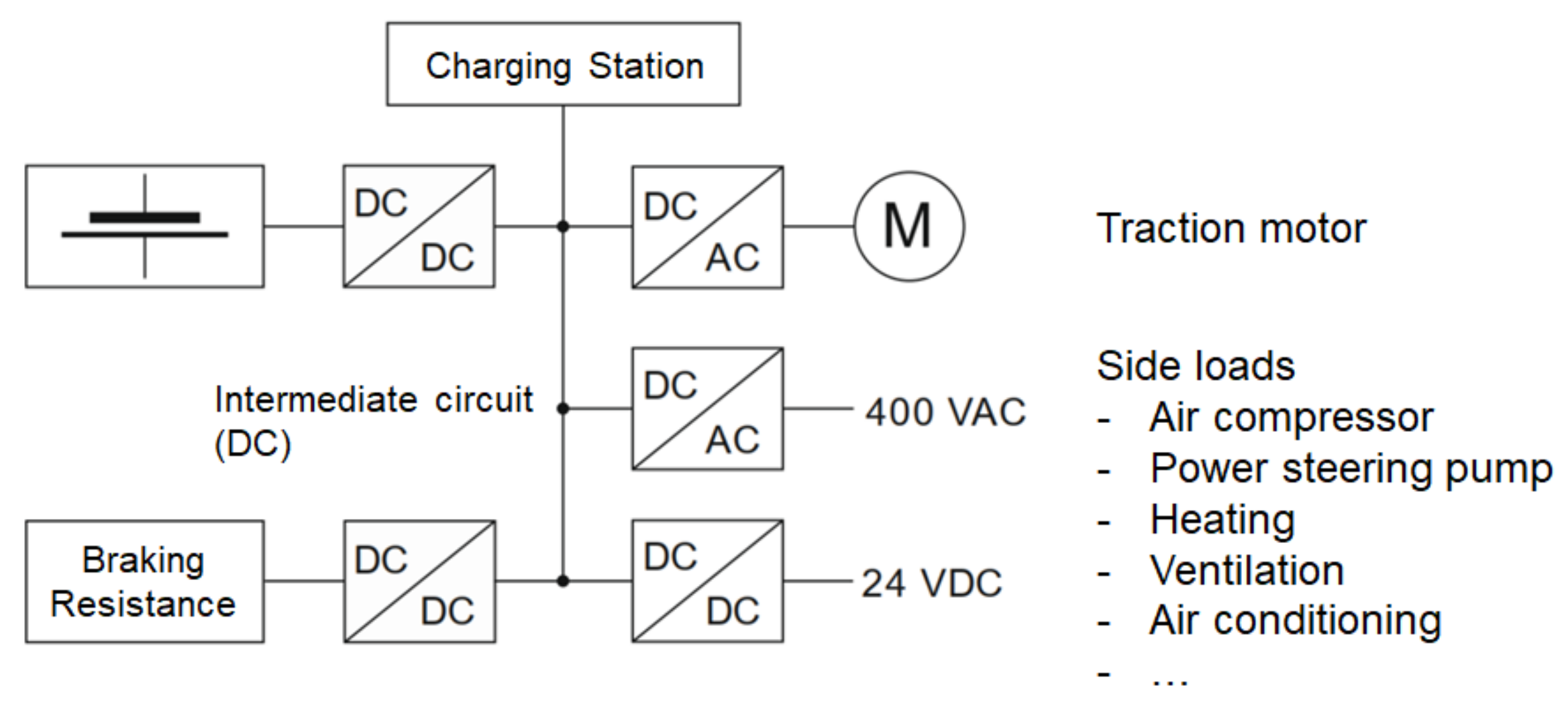
2.1.2. Electric Architecture

Regarding the electric architecture, a DC intermediate circle is typically used in combination with DC/DC converters and DC/AC converters for the electric consumers. The typical voltages are 650 to 750 VDC for the battery relative to the intermediate circle. The typical voltages of electric consumers, such as an air conditioner or air compressor, are 400 VAC. Additionally, there is a 24 VDC voltage level for electric consumers that have a lower electric power demand. Components with high power consumption, such as a fully electric resistance heater (see also Section 2.3.2), are typically operated with high voltages, either on the high voltage DC level or with the 400 VAC level. An example of a battery-powered bus electric architecture is shown in Figure 2 [2,11].

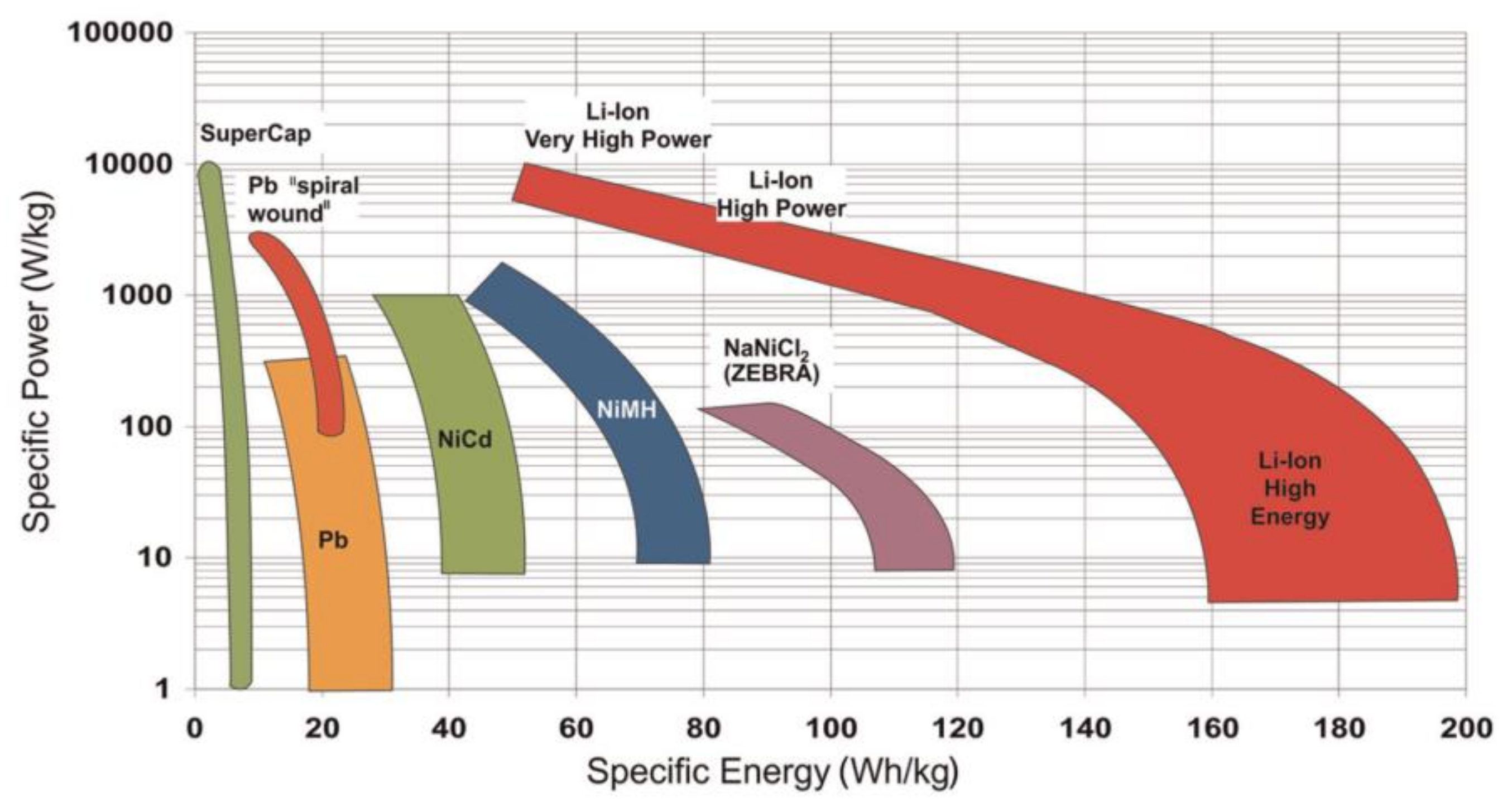
2.1.3. Battery Systems Used in Electric Buses

Regarding battery systems in battery-powered electric buses, only battery systems based on lithium-ion batteries are currently used. A basic distinction is made for high-energy batteries and high-power batteries. High-energy batteries typically have higher energy at a lower power density. High-power batteries typically have higher power densities but lower energy densities. An overview of electric energy storage technologies with a focus on battery technology is shown in Figure 3.
As one state-of-the-art manufacturer of batteries for bus applications, Akasol is highly regarded in the authors’ view, and is the battery supplier for the aforementioned EvoBus eCitaro, among others. Batteries from this supplier that are used in buses can use either NMC (lithium nickel manganese cobalt oxide) for high-energy batteries or LTO (lithium titanate) for high-power batteries, or a combination of both [13]. The cost for NMC is stated to be approx. 420 $/kg (≈389 €/kWh), and for LTO, the cost is approx. 1005 $/kg (≈931 €/kWh) [14]. Another battery type that is often used is LFP (lithium iron phosphate) [9]. The price of this type of battery is stated to be 580 $/kWh (≈537 €/kWh).
Regarding an ultra-high-energy battery, Akasol is offering the AKM CYC battery system with a capacity of 42 kWh, a mass of 230 to 260 kg, and a volume of 17.85 L per battery pack, resulting in a gravimetric energy density of 162 to 183 Wh/kg and a volumetric energy density of 235 Wh/L. A continuous performance of 20 to 32 kW is stated, resulting in a power density of 77 W/kg to 139 W/kg. These values are in good agreement with the numbers for the high-energy batteries shown in Figure 3 [15]. Regarding an ultra-high-power battery system, Akasol is offering the AKM POC battery system. For the AKM 53 POC, a capacity of 35.3 kWh at a weight of 333 kg, a volume of 25.05 L, and a continuous performance of 60 kW are stated. This results in a gravimetric energy density of 106 Wh/kg, a volumetric energy density of 141 Wh/L, a gravimetric power density of 180.2 W/kg, and a volumetric power density of 240 W/L. However, the peak performance of discharging is stated as being 270 kW, leading to a power density of 811 W/kg (1078 W/L). For charging, the peak performance is 106 kW, offering a power density of 318 W/kg (423 W/L). The peak performance of this battery system is in agreement with the numbers given in Figure 3 [16].
Furthermore, the latest numbers regarding future estimations of battery systems for electric buses are given in the literature. For the batteries of the eCitaro, Akasol is planning to raise the capacity in 2020 by replacing the currently used battery packs with the latest battery technology, enabling a maximum capacity of 330 kWh. Another step that might be taken within the next few years is to replace the currently used NMC batteries with solid oxide batteries. This would allow for a maximum capacity of up to 400 kWh within the same space due to a higher gravimetric energy density, according to EvoBus [10].
One last thing that must be considered regarding batteries for electric buses is their lifetime. Buses are typically in operation for 12 to 14 years, as reported by Schwarzer [17]. Due to degradation, the batteries have to be changed after about half of the bus’s operation time. As a criterion for changing the battery, a state of charge (SOC) of 80% is recommended. Factors to consider that come along with changing the battery are the high cost for a new battery and ecological aspects, such as high CO2 emissions during the production process. To at least partially overcome this, batteries from electric buses are considered to be used as stationary energy storage as a second-life application [2,18].

2.2. Charging Strategies for Electric Buses

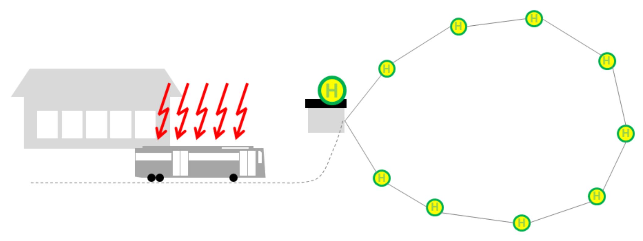
2.2.1. Overnight Charging

In an overnight charging scenario, buses are fully charged at the bus terminal. Since the charging is typically done at night, outside the service hours of city buses, it is called overnight charging. In this scenario, the energy needed for the whole service is stored within one charge. Regarding the charging infrastructure, only one location, which is normally the bus terminal, needs to be equipped. However, buses suitable for this scenario require high energy storage capacities. For this reason, the battery types used for this scenario are high-energy batteries (see Section 2.1.3). A visualization of the described charging scenario is shown in Figure 4 [2].

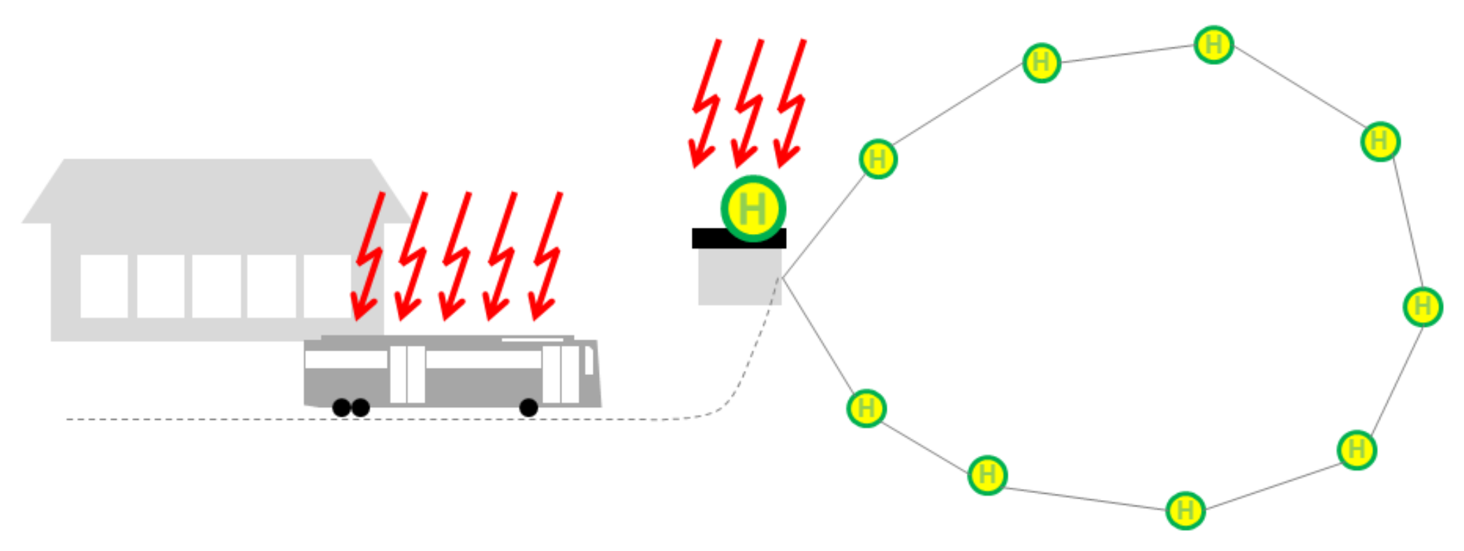
2.2.2. Opportunity Charging at Final Stops

During opportunity charging at final stops, in addition to the charging at the bus terminal, charging is done at the final stop of a city bus´s route. For this, the regular stop at the final stop is used. Stop times at final stops can be within the range of a few minutes up to 20 or 30 min, according to Berthold [19]. Buses being operated in such a scenario require lower energy storage capacities compared to buses operated in an overnight charging scenario. However, the effort required for the installation of the charging infrastructure rises since more locations than just the bus terminal have to be equipped. For this scenario, high-power batteries are typically used (see Section 2.1.3). A visualization of the described charging scenario is shown in Figure 5 [2].

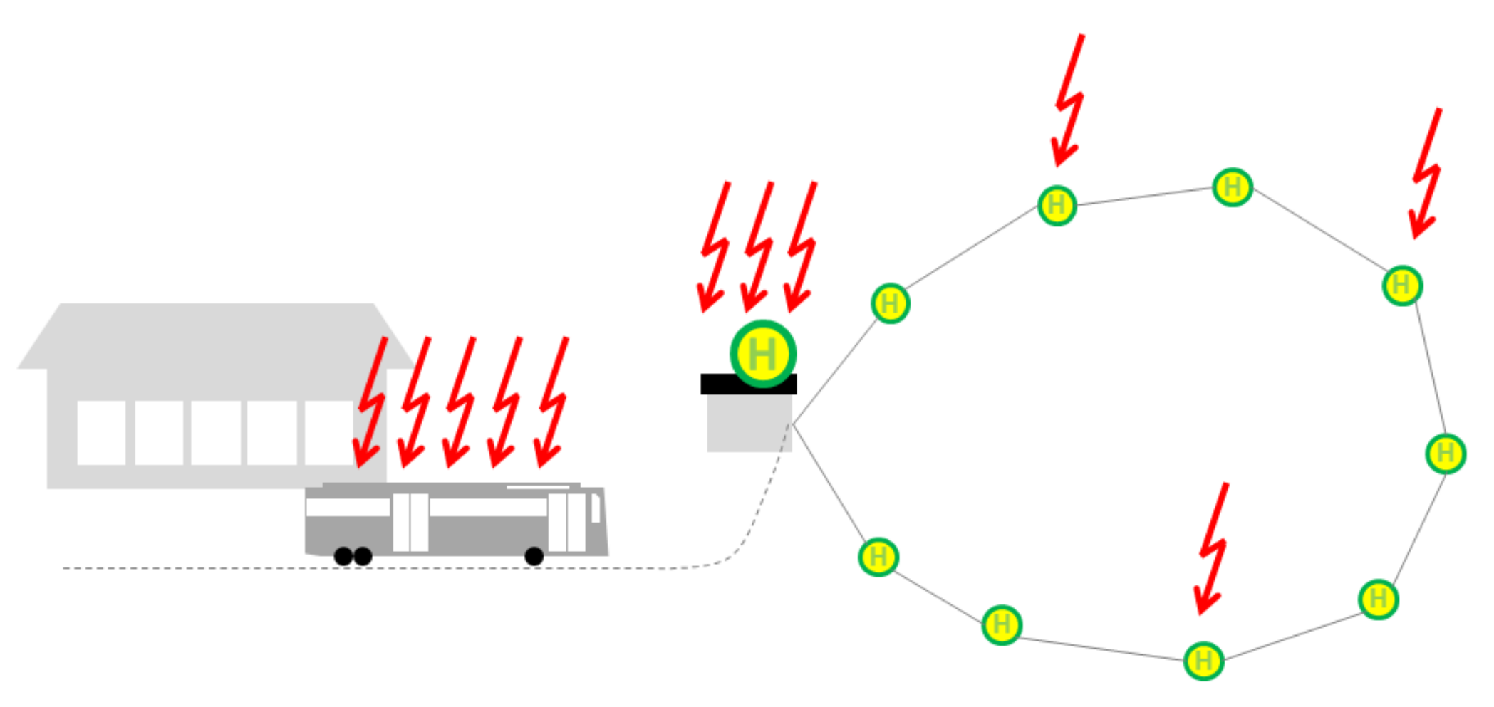
2.2.3. Opportunity Charging at Multiple Stops

Another variation of the opportunity charging scenario is the opportunity charging scenario taking place at multiple stops, as illustrated in Figure 6. Besides the installation of the charging infrastructure at the bus terminal and the final stops, the charging infrastructure at regular bus stops is installed. Since the stop times at regular stops are pretty short (typically within the range of 20 to 90 s, according to Cundill and Watts [20]), high charging powers are required to be able to recharge significant amounts of energy. Regarding the charging infrastructure, an even higher amount of effort is necessary since more locations have to be equipped; however, the storage capacities of the buses can be lowered. For this charging scenario, ultra-high-power batteries are required (see Section 2.1.3) [2].

2.3. Heating Systems for Electric Buses
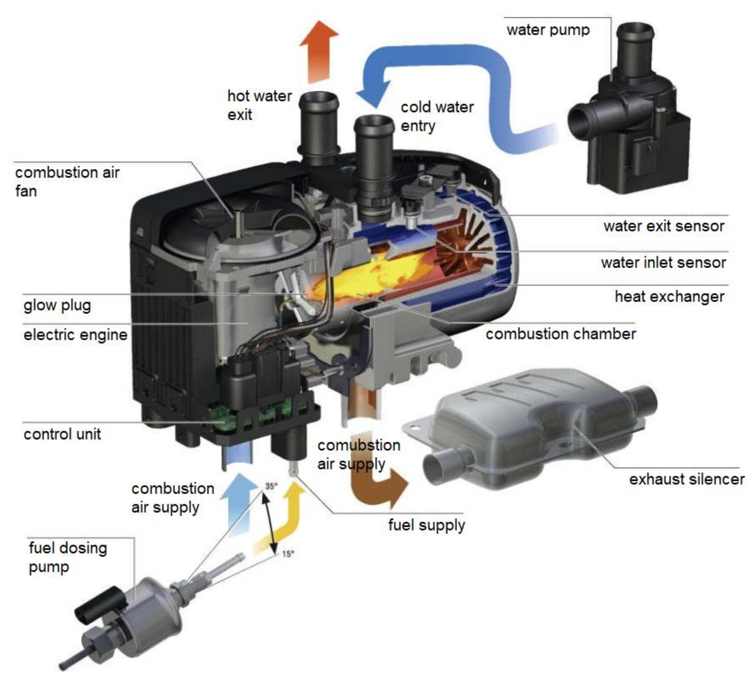
For providing the high thermal capacity necessary for interior heating, as shown in Figure 1, three main solutions are currently used in battery-powered electric vehicles. These solutions are fuel heaters, electric heaters, and heat pumps. Another solution found in the literature and regarded as relevant for conducting the requirements of THS is thermal energy storage proposed by Fraunhofer (Kratzing) and Konvekta (Best). However, this solution is currently in the development and field testing stage. The three state-of-the-art heating solutions and the thermal energy storage in development are further described within the next sections. Additionally, the typical architecture of the thermal management system of a battery-powered electric bus is shown.

2.3.1. Fuel Heater

Fuel heaters burn a liquid fuel and provide the released heat of the burning process to the air, or in most cases, to the vehicle’s cooling fluid. Regarding the fuels used, in general, all kinds of liquid fuels, such as diesel, gas, ethanol, bio-fuel, etc., can be used. However, diesel is usually considered as the main choice. The benefit of using fuel heaters as the heater for battery-powered electric buses is the fact that no electric energy from the battery is needed for heating purposes. A negative aspect of burning fuels is local emissions, which is in contradiction with the local emission-free purpose of using an electric bus. The fuel consumption of a fuel heater for a 12 m standard bus is about 2.9 L/h, with a thermal output of 24 kW, according to the manufacturer, at an efficiency of about 76.5% to 79.5%, according to Sonnekalb et al. [21,22]. Considering a city bus’s average speed of 12 km/h (SORT (Standardised on-road test cycles) heavy urban cycle [23]), this would result in fuel consumption of 24.2 L/100 km.
Typically, fuel heaters are available with different performance levels. Adjustment is mostly done using a simple ON/OFF operation. Regarding the conditions for switching on or off, the temperature of the cooling fluid is measured. According to Valeo, switching on is done when the cooling fluid temperature falls below 70 °C, while switching on is done when it goes above 85 °C. Communication with the vehicle is realized by using the CAN (Controller area network) interface, and the electric power supply is provided by connecting to the 24 V supply of the vehicle [22,24].
When it comes to maintenance, fuel heaters require at least a yearly service. However, due to the formation of soot, cleaning can be necessary more often. To keep this cleaning frequency as low as possible, a minimum burning period of 2 min is implemented during operation. Regarding maintenance and self-protection of the heater, a minimum volume flow of the cooling fluid through the heater is required to ensure a high enough heat transfer and to prevent the heater from overheating. Furthermore, a bimetal switch is used to realize a switch-off function at a temperature of 135 °C. Figure 7 shows the assembly of a fuel heater from Eberspächer (Esslingen, Germany) [24].
The dimensions of a fuel heater by Eberspächer with a thermal output of 24 kW are 600 mm × 230 mm × 222 mm, which is a volume of 30.6 L. The mass of such a system is stated to be 18 kg [22].

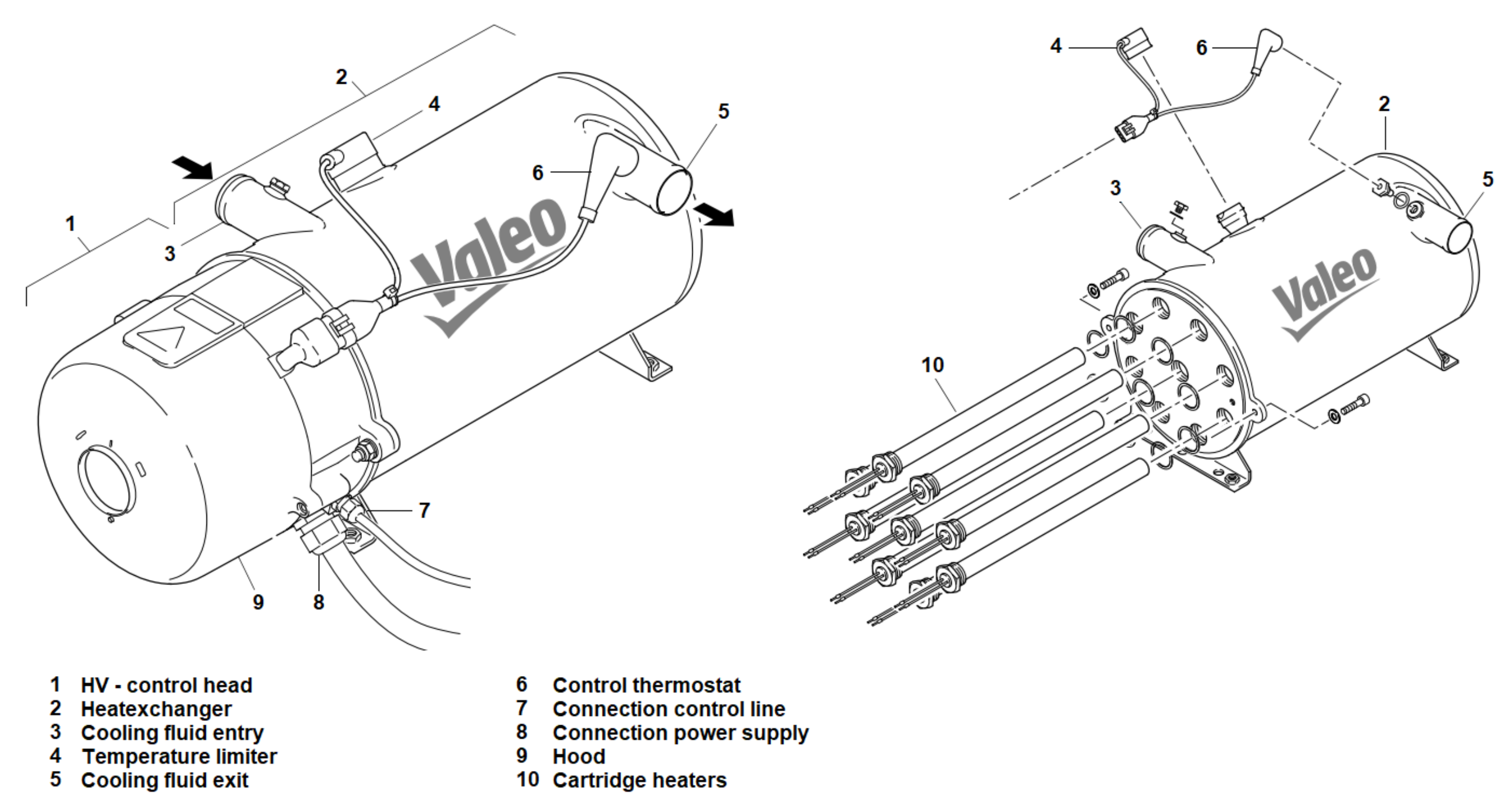
2.3.2. Electric Heater
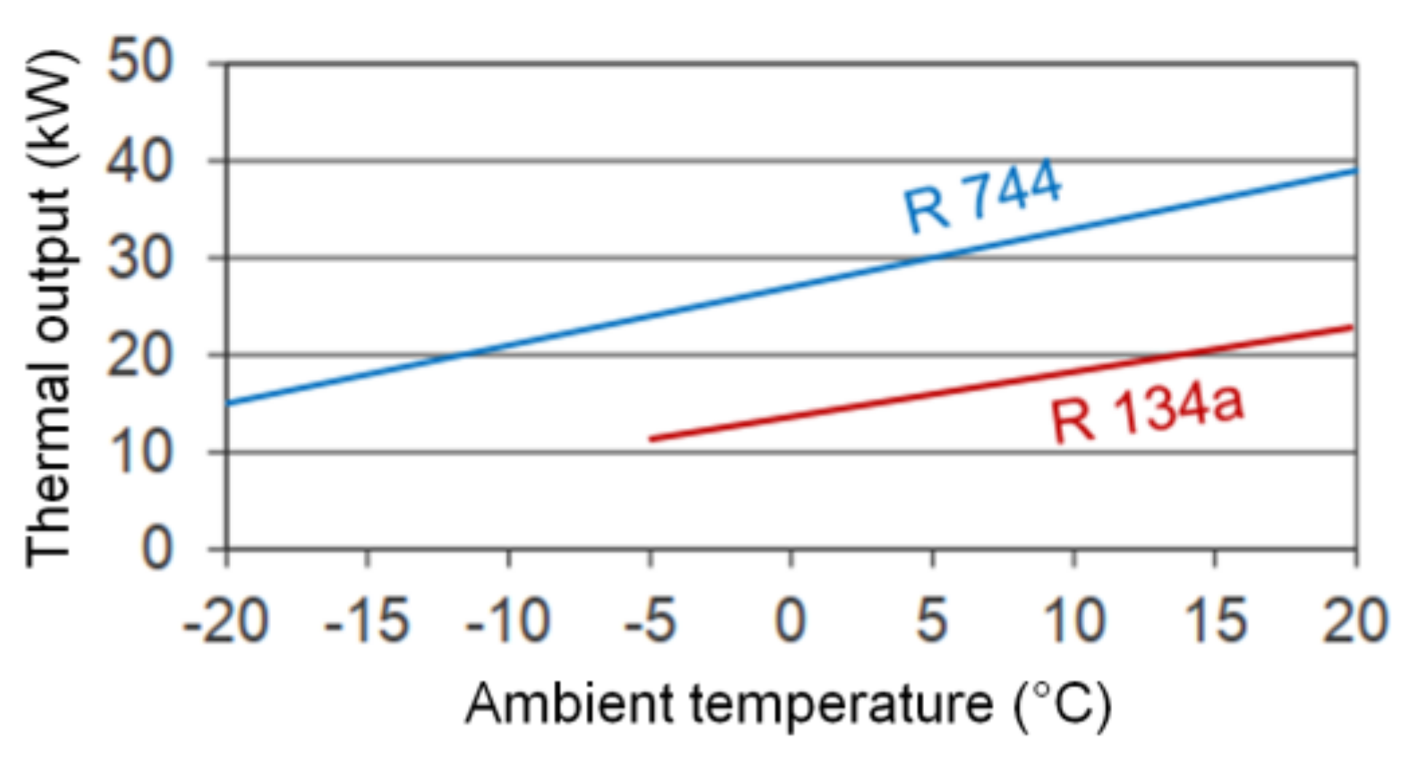
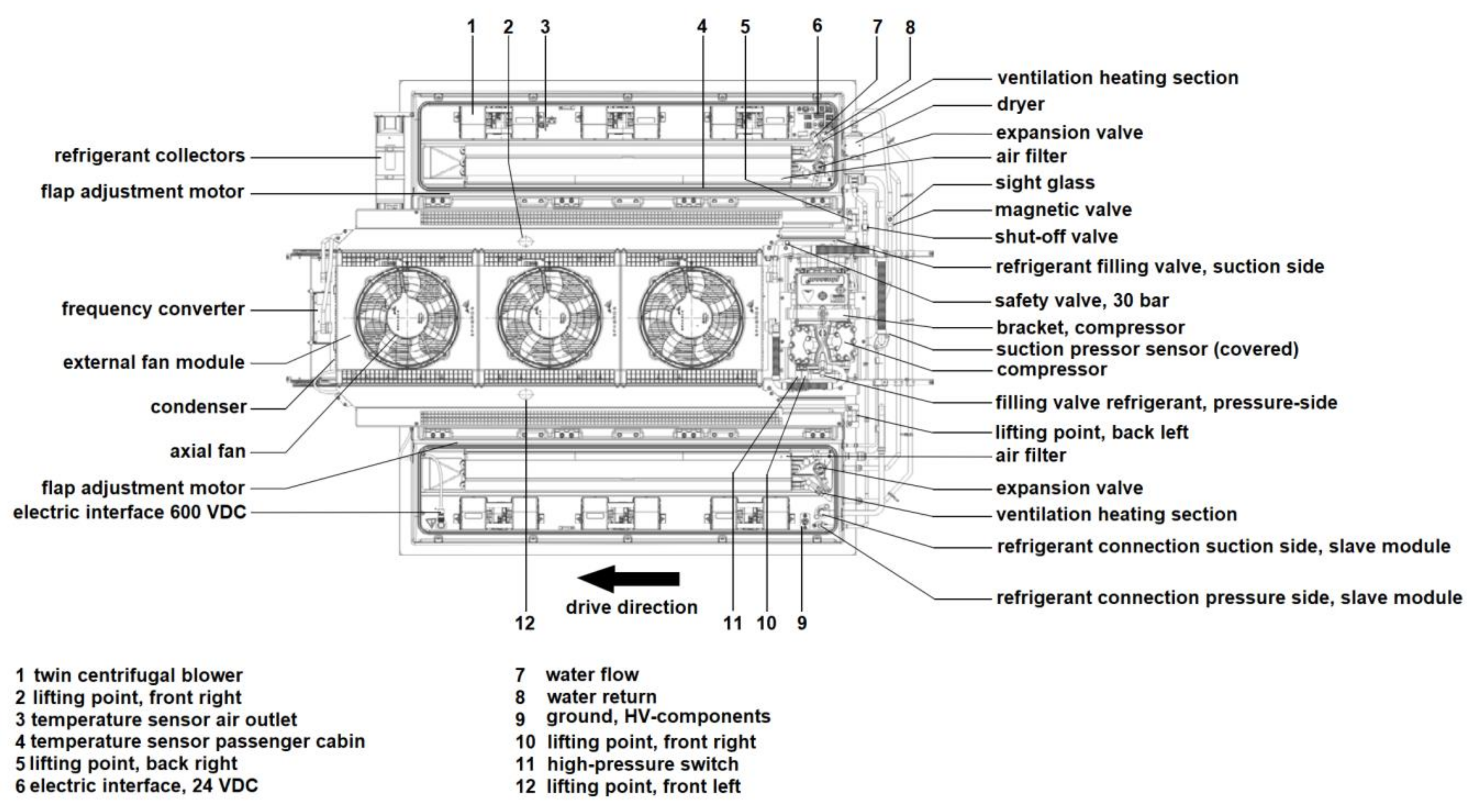
Electric heaters, as shown in Figure 8, transform electric energy into thermal energy, which is transferred to the air or the vehicle’s cooling fluid. Regarding heating elements, PTC (Positive Temperature Coefficient)-heaters or resistance heaters are used. The benefit of electric heaters is that it is an easy technology and there is a lack of emissions from heating. However, electric energy from the battery is used, leading to a potentially high range reduction when heating is required due to the direct transformation of electric energy to thermal energy (at an efficiency of about 98% without considering the battery’s efficiency).
Just as with the aforementioned fuel heaters, electric heaters are available with different performance levels. Furthermore, adjustment is typically done using ON/OFF operation with switch-on and switch-off temperature thresholds (e.g., 68 °C and 75 °C, respectively, for the Valeo Thermo AC/DC). For the electric power supply, electric heaters can either be connected to a DC with typical voltages of 600 to 750 VDC or to 400 VAC. For communication with the vehicle, the CAN interface is used, as well as the 24 V power supply of the bus [11,25].
Regarding maintenance, at least a yearly service is required. To simplify servicing, typical wearing parts, such as cartridge heaters, are designed to be exchangeable, as shown in Figure 8. Regarding the self-protection of the heating unit, a minimum volume flow of the cooling fluid, a trail of the cooling fluid pump of at least 2 min, and a switch-off threshold of 125 °C are implemented [25].
The dimensions of an electric heater from Valeo with a thermal output of 20 kW are 578 mm × 247 mm × 225 mm, which is a volume of 32.1 L. The mass of such a system is stated to be 15 kg [11].
A special version of an electric heater uses braking resistance. Every bus should have a continuous braking unit according to German traffic regulations. In terms of electric buses, this continuous braking unit is typically conducted as an electric resistance heating unit. In the case of the EvoBus eCitaro, it is connected to the vehicle’s cooling fluid circle. Due to this, it can be used for heating purposes. Further description of this is given in Section 2.3.5 [26,27].

2.3.3. Heat Pump

By using heat pumps, the heating capacity can be provided with a COP (Coefficient of performance) of greater than 1 due to the use of a refrigerant circle that is mostly driven by an electric compressor [28]. Regarding the heat source, ambient air is used, while the heat sink is the air provided to the cabin. The electric energy for powering the compressor is taken from the vehicle’s traction battery. Most heat pumps used within existing vehicles nowadays use R134a as a refrigerant; however, the use of R134a has been prohibited in newly registered vehicles since 2017 due to its high global warming potential (GWP). Recently introduced heat pumps use CO2 as the refrigerant [28,29,30,31,32,33].
Using CO2 as a refrigerant requires higher process pressures; however, this leads to benefits regarding the thermal output. The COP values stated by Konvekta are 4 for an ambient temperature of 15 °C, 2.5 at 0 °C, 2.2 at −5 °C, and 2 at −10 °C [28,34]. Figure 9 shows a comparison of the performance as a function of the ambient temperature between heat pumps designed for buses with R134 and R744 (which is CO2) as the refrigerant. It can be seen that the thermal output that can be provided by a CO2 heat pump is higher compared to a heat pump using R134a. Additionally, the thermal output can be provided for temperatures as low as −20 °C, while for the heat pump using R134a, a thermal output for temperatures as low as about −5 °C is stated. Referring to Basile et. al, the operation of a heat pump using R134a as refrigerant is not useful [34]. However, Lee [35] states that for electric vehicles (not buses), the operation of a heat pump using R134 could be possible, even below, even below −10 °C. Besides the positive effect of an overall reduction in energy consumption for heating using heat pumps, the range reduction is less compared to using electric heaters for heating. However, electric energy from the battery still must be used for heating. Additionally, the efficiency of a heat pump decreases with decreasing ambient temperature, which increases the heating demand. Furthermore, for very low temperatures of around −10 °C or less, an additional heating system is required, even when using a CO2 heat pump, since the thermal output cannot fulfill the heating demand of the vehicle anymore. Another aspect that must be considered is the icing of outer heat exchangers within specific temperature ranges, which leads to a reduction in efficiency and requires a defrosting system [28,36].
Regarding the adjustment of the thermal output, several performance levels can typically be set. This is done via frequency adjustment of the compressor. An optional infinitely variable control is possible, too. When the adjustment is done using defined performance levels, surplus produced heat must be extracted to the ambient air. For the electric power supply, the heat pump system is connected to the DC level. Since the compressor is working with three-phase 400 AC, a frequency converter is used in between. Communication with the vehicle is done via the CAN-interface [31,38].
Since a heat pump is a more complex system than a fuel heater or an electric heater, as seen in Figure 10, maintenance is essential. Regular maintenance is required on a six-monthly basis. For safety reasons, permanent monitoring of all sensors and checks of the plausibility of the measured values is done. In case of any irregularities, the heat pump will be switched off [38,39].
The dimensions of a REVO-E heat pump from Valeo with a thermal output of 16 kW (cooling power of 25 kW) and R134a as the refrigerant are 2800 mm × 2091 mm × 406 mm, which is a volume of 2377 L. The mass of such a system is stated to be 272 kg [29]. The dimensions of an UltraLight 500 heat pump from Konvekta with a thermal output of 18.2 kW (cooling power of 20 kW) and CO2 as the refrigerant are 2124 mm × 2045 mm × 366 mm, which is a volume of 1590 L; the mass of this heat pump could not be found in the design proposal [33].

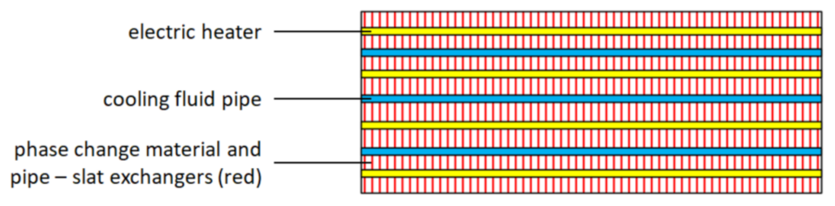
2.3.4. Thermal Energy Storage

Very recently, a thermal energy storage system for the interior heating of an electric city bus was proposed by Fraunhofer and Konvekta. The basic idea is the same as it is for the use of THS. The thermal energy storage and the battery can be electrically charged simultaneously, where the stored heat is used for interior heating to keep the electric energy stored in the battery for driving. For this thermal energy storage, a prototype was built and investigated in a laboratory. A field test on a real bus is planned but has not been conducted yet [40,41].
Regarding the storage material, paraffin wax is used within this storage system. The melting temperature of this material is about 69–71 °C, the storage capacity is 260 kJ/kg (sensible and latent heat within the temperature range of 62–77 °C), the densities are 0.88 kg/L (solid) and 0.77 kg/L (liquid), the heat conductivity is 0.2 W/mK, and the maximum working temperature is 100 °C [40].
The storage is designed to be in a rectangular shape. For charging, electric resistance heaters (720 VDC) are used, while for discharging, pipe–slat heat exchangers are brought directly into the storage material. Regarding the discharging medium, the cooling fluid of the vehicle is used. The conceptual design of the storage setup is shown in Figure 11, while an outer view of the installed storage is shown in Figure 11.
For integration into the bus, a modular design with six modules is planned. Each module should have a storage capacity of 2.25 kWh, a charging power of 20 kW at 680 VDC, and a storage density of 39 Wh/kg. The positioning of the storage modules is intended to be spread over the interior of the vehicle, as shown in Figure 12 [40].
Regarding the potential benefits of the storage system, a high lifetime with more than 16,000 full cycles, no need for an exchange due to degradation, and a much lower cost compared to batteries is stated. However, with a very low gravimetric energy density of 39 Wh/kg, the weight is a potential disadvantage of this system. Furthermore, the volumetric energy density of the storage system could be quite low since the density of the phase change material itself is low and the need for slats for improving the charging and discharging behavior requires volume as well. A specific volumetric energy density is not given within the design proposal [40].

2.3.5. Thermal Management Architecture

To give an idea of how the aforementioned components are implemented into an electric-powered city bus, the architecture of the thermal management is described within this section. As an example, the thermal management architecture of the EvoBus eCitaro is shown in Figure 13.
The relevant components for the interior heating are the CO2 heat pump on the roof of the bus, the braking resistance in the rear, the additional heater in the rear, the floor heater, and the frontbox. The other components shown in Figure 13 are more connected to cooling functions and thermal management of the battery, and therefore are not further described. The CO2 heat pump on the roof delivers heat to the interior through the air that flows into the cabin from the top. The braking resistance serves to heat the interior, alongside its use for energy recuperation and emergency braking. The additional heater is used as a fuel heater burning diesel fuel (or biodiesel fuel in the case of second-generation heaters). The additional heater can be used at very low temperatures when the thermal capacity of the heat pump is not sufficient and no extra electric energy should be used for heating to maintain the range of the bus. To bring the heat from the braking resistance and the additional heater into the interior of the vehicle, both are connected to a cooling fluid circle. The cooling fluid circle is connected to floor heaters within the passenger cabin and to the frontbox within the driver’s cabin, which are heat exchangers used to bring the heat from the cooling fluid into the cabin [26].

2.4. Challenges Regarding the Use of Electric Buses

As reported in the introduction, the spread of electric buses is currently very limited. Reasons for this are, in the authors’ opinion, two main facts: the high investment costs and the limited ranges, which are dependent on the ambient temperature, especially when heating is required. To emphasize both aspects, this section provides further information beyond that which is provided in the introduction.
The first challenge to be discussed is the high investment cost for battery-powered electric buses compared to conventional diesel buses. As reported by Knote, prices are roughly twice as high for battery-powered electric buses compared to diesel buses [2]. Since public transport is not economical for traffic enterprises in most cases, subsidization is mostly required to keep a high level of public transport services. A reason for the high investment cost of battery-powered electric buses is the high prices for the batteries, as described in Section 2.1.2. When considering a battery price of 500 €/kWh, which is at the lower end of the range given in Section 2.1.2, the battery price for the discussed example of the eCitaro would be about €146,000. Since a 12 m diesel bus costs approx. €240,000 to €350,000 [2], the battery alone accounts for about half of the cost of a whole conventional diesel bus.
The second challenge to be discussed is the insufficient range of battery-powered electric buses in non-ideal ambient conditions, especially in winter conditions when interior heating is required. A further explanation of this issue is given in Figure 14. On the x-axis of Figure 14, the distance of a city bus’s daily tour relative to the range of a battery-powered electric city bus is given. On the y-axis, the number of tours relative to the tours that can be covered is given. Therefore, the blue line represents the relative number of tours covering the given distance as a function of the relative number of tours that can be covered with a city bus offering the range given on the x-axis. To show the number of tours that electric city buses can cover, grey bars are given using the EvoBus eCitaro as an example. As before mentioned, this bus is offering a range of 280 km under ideal ambient conditions, which is stated to be 20 °C. Referring to the diagram, a range of 280 km is sufficient to cover 70% of all tours within the German bus transport system. However, when interior heating is required, the range of the bus decreases if heaters consuming electric energy are used, and therefore the number of tours that could be covered with the bus decreases as well. Using an ambient temperature of about −10 °C as an example, interior heating of about 1.4 kWh/km is required, according to Figure 1. Since the eCitaro is offering an electric CO2 heat pump, the electric energy consumption is reduced. According to the manufacturer, a COP of about 2 can be reached at an ambient temperature of −10 °C, leading to energy consumption of about 0.7 kWh/km for heating [33]. Together with an energy consumption of 1.04 kWh/km for traction (calculated based on the battery capacity and maximum range), the overall energy consumption would be approx. 1.74 kWh/km, leading to a maximum range of approx. 167 km. As can be seen in the diagram, a range of 167 km would be sufficient for only about 10% of all tours.
Due to the described range reduction when interior heating is required, the usability of electric city buses is strongly dependent on the ambient conditions. For traffic enterprises, this would mean that electric buses can only be used on tours with low distances if the buses are to be used throughout the year and no charging infrastructure for opportunity charging is to be built.
Based on the above discussion regarding the challenges faced, it can be concluded that providing a low-cost energy storage system for interior heating can have a major impact on the spread of battery-powered electric buses. Besides lowering the cost for the buses itself, it could reduce the necessity of installing opportunity charging infrastructure, which is currently vital if relevant ranges are to be offered independent of the ambient conditions. However, installing opportunity charging infrastructure is neither possible at any location nor affordable.

3. Requirements for Thermal High-Performance Storage

The requirements for THS are separated into eleven different categories. The derivation for each category is described within each respective section.

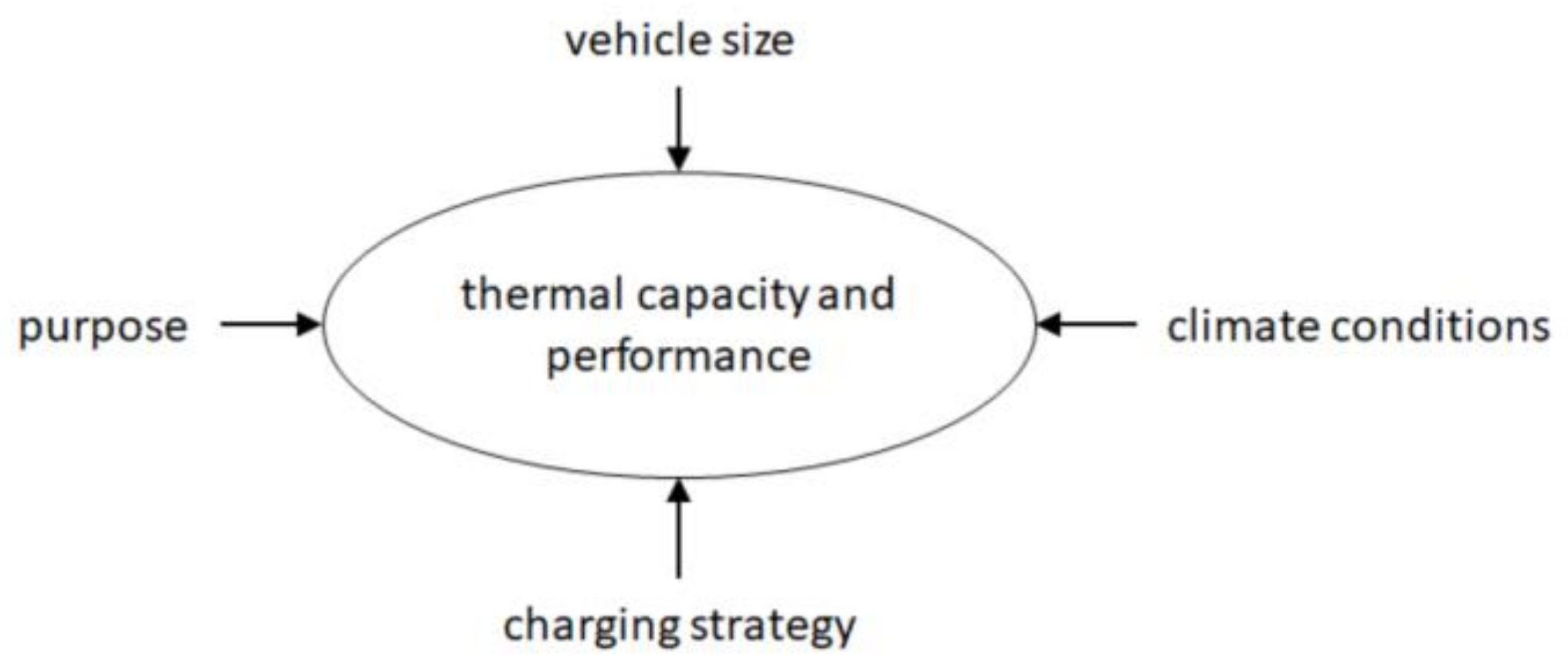
3.1. Thermal Capacity and Performance

Thermal capacity and performance are described together within one section since both are influenced by the same parameters, where performance refers to the charging (electric power) and discharging (thermal output) performances. Both are influenced by the purpose, vehicle size, climate conditions, and charging strategy. Figure 15 visualizes the influence of these parameters.
The term “purpose” refers to whether the THS is used as the only heating system within the vehicle or whether it should be used as an additional heating system complementing the heat pump. If it is used as the only heating system, it has to cover any heating demand from the vehicle. If it is used as a complementary system, it only has to cover the gap between the maximum thermal output of the heat pump and the heating demand of the vehicle.
The vehicle size is highly relevant since the heating demand of a vehicle is strongly dependent on its interior volume, as described by Grossmann [42]. Since this fact is regarded as trivial, no further description is given.
Regarding climate conditions, two basic thoughts must be considered. The first one is that a bus, especially a city bus, is typically used in one fixed location. Since the climate conditions for one location are well known and do not change significantly over the typical lifetime of a bus, THS can be adopted precisely for these conditions. However, climate conditions can vary greatly between locations. For example, there would be a huge difference between the climate conditions of a city in Scandinavia, such as Oslo or Stockholm, and a city in southern Europe, such as Rome or Madrid. The second thought to be considered is that the thermal output for heating varies greatly depending on the ambient temperature, as already shown in Figure 1. Since a bus is used throughout the year, as well as typically throughout the day, the heating demand can vary greatly throughout both a year and a day. A very strong variation over the year is typically connected to areas with a very continental climate, such as in Central Northern America (e.g., Winnipeg in Canada) or central Asia (e.g., Astana in Kazakhstan). High variations of the temperature throughout a day often occur in desserts, and therefore in cities built in desserts, e.g., in Las Vegas (USA) or Tehran (Iran) [43,44,45,46].
To clarify the effect of different charging strategies on THS, some basic calculations were conducted based on the assumptions on two extreme scenarios: one extreme overnight charging scenario and one extreme opportunity charging scenario. For the extreme overnight charging scenario, it was assumed that the overall daily drive time of a bus was 17 h and the following time for charging was 7 h. Assuming a very cold winter day with a very low ambient air temperature (e.g., in Scandinavia, Canada, etc.), this led to an energy demand for heating of 425 kWh (assumed required thermal output of 25 kW, which is sufficient for −25 °C, according to Valeo; assuming an average speed of 17 km/h (SORT easy urban), this would lead to a heating demand of 1.47 kWh/km, which would be sufficient for about −15 °C according to Figure 1). To charge THS with such a high capacity within 7 h, a charging power of 60.7 kW would be necessary. Out of these values, two indicators can be calculated that relate the storage capacity to the charging power vs. the discharging power. For charging power, it is 7 kWh/kW, while for discharging, it is 17 kWh/kW. The boundary conditions for the extreme opportunity charging scenario are a drive time of 0.47 h (28 min) and a charging time of 0.05 h (3 min), according to data regarding public transport in Amsterdam [47]. Using the same climate conditions as described for the extreme overnight charging scenario, the required storage capacity and charging power are 11.7 kWh and 234 kW, respectively. The aforementioned indicators were calculated to be 0.05 kWh/kW for charging and 0.47 kWh/kW for discharging. Comparing the indicators for both scenarios, there is a factor of about 140 for the charging indicator and 36 for the discharging indicator between both scenarios. Based on this, it can be concluded that the requirements for THS regarding storage capacity and charging/discharging performance vary greatly depending on the charging scenario.
From the given descriptions, it can be concluded that no specific requirement regarding capacity and performance can be stated. Capacity and performance have to be specifically chosen for the given scenario such that the THS is neither oversized nor undersized. Due to this, THS has to be designed to meet its specific purpose.

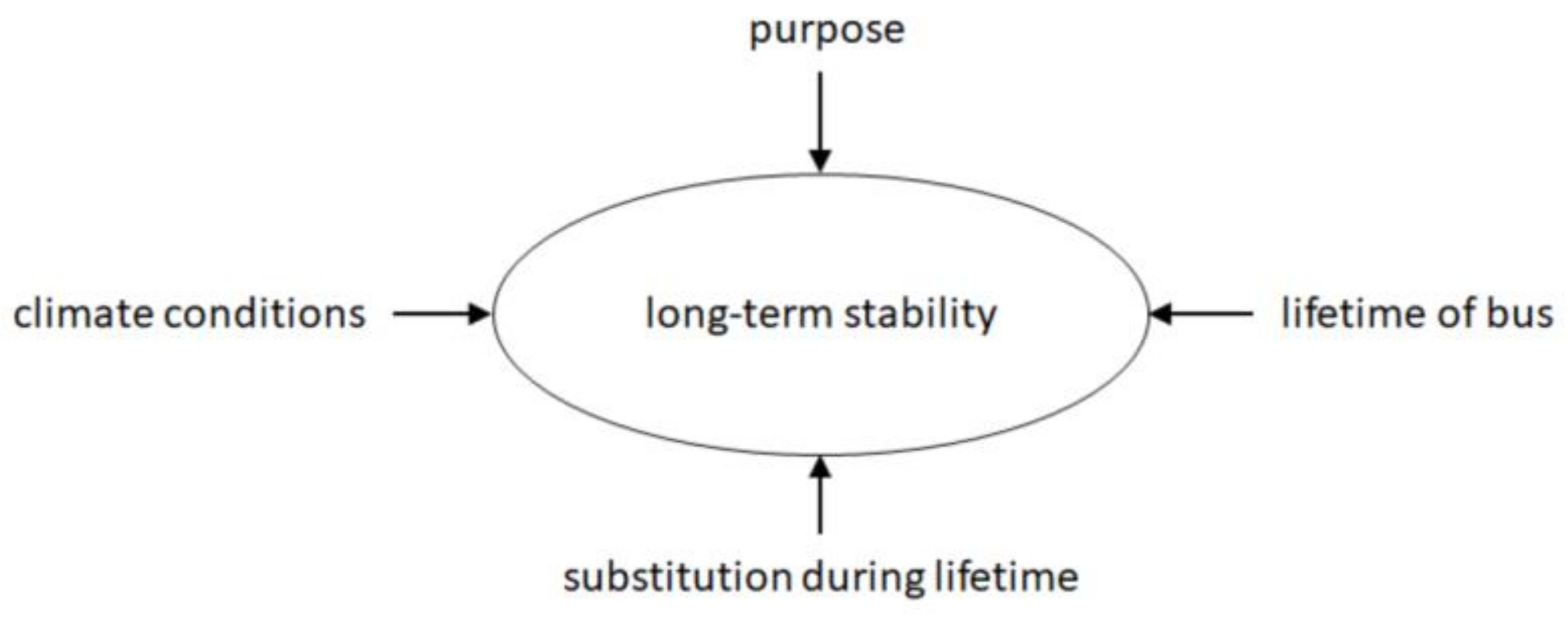
3.2. Long-Term Stability

The parameters that influence the long-term stability of THS are visualized in Figure 16. The main influences are the climate conditions, purpose, lifetime of the bus, and a potential substitution during the lifetime.
The first parameter is the climate conditions, which significantly influence THS since they determine whether there is a heating demand at all (heating demand only occurs below an ambient temperature of 15 °C according to Figure 1). If there is no heating demand, the THS does not need to be in operation.
The second parameter is the purpose. If the THS is used as the only heating system, it is in operation any time there is a heating demand. If it is used in addition to a heat pump, it is regularly only used if the thermal output of the heat pump is insufficient. To emphasize the influence of this, the climate data of Stuttgart is considered as an example. According to a test reference year dataset from the German Meteorological Service, temperatures of 15 °C or below occurred for 73% of that year. However, temperatures of −10 °C or below (the minimum temperature a CO2 heat pump is sufficient as the only heating system according to Section 2.3.3) only occurred for 0.05% of that year.
The third parameter is the typical use time of a bus. With a yearly average mileage of about 57,000 km, according to Goebelt, an overall expected mileage over the lifetime of a bus (see Section 2.1.3) is 684,000 km to 798,000 km [48]. Considering an average speed of 12 km/h according to the SORT heavy urban cycle, the overall expected use time for a bus is 57,000 to 66,500 h [23].
Based on the aforementioned aspects, the expected lifetime was calculated based on use in Stuttgart for both cases. Considering a use time of the bus of 66,500 h and the probability of a heating demand of 73%, an overall long-term stability of 48,545 h would be required, which expresses an extreme maximum value for this location. Combining the lifetime of 57,000 h with the probability of 0.05%, a long-term stability of 28.5 h would be the result, which expresses an extreme minimum value for this location. A final thought on the long-term stability is the fact that THS could be substituted within the lifetime of a bus, similar to what is done with a battery, as described in Section 2.1.3. The parameter influencing this decision would probably be the cost. If it is cheaper to replace the THS after a while than manufacturing new THS that would last for the whole lifetime of a bus, a replacement would probably be preferred.
Based on the aforementioned discussion, it was concluded that the requirement for long-term stability cannot be generally described. Some particular use cases might not need much long-term stability. However, there are potentially many use cases that require long-term stabilities of several thousand or even tens of thousands of hours. Since the development of THS should be done in a way that as many use cases as possible can potentially be covered, long-term stability of several thousand or tens of thousands of hours is stated as the primary requirement in this category.

3.3. Mass and Volume

As is generally known, mass and volume are properties of high relevance in mobile applications, especially for vehicles. However, a more detailed look at both factors for buses leads to the conclusion that mass is regarded as more relevant for application in battery-powered electric buses than volume. Following reasons were found to explain why volume should not be rated as high as mass:
  • The roof of a bus, which offers lots of space, is typically used for components like the air conditioner/heat-pump and for energy storage, such as batteries. Furthermore, THS could be placed on the roof.
  • Components like ticket machines are sometimes installed within the interior of a bus, leading to a reduction in the number of seats. Due to this, installing extra components within the interior does not seem to matter much.
  • Seats above wheel cases are often less spacious compared to the other seats within a bus and therefore are often less comfortable for passengers. Replacing these seats with other components should therefore not matter significantly.
  • The space below seats often is not used at all.
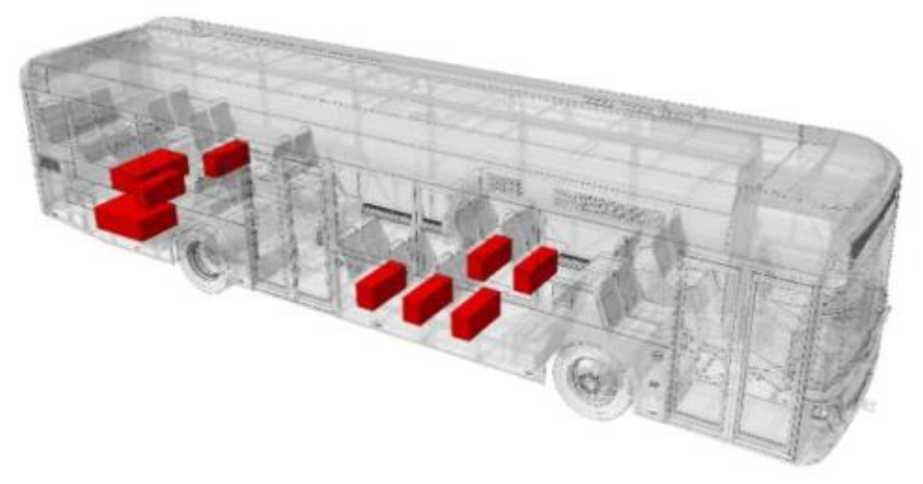
  • Battery electric buses typically have a higher weight compared to diesel buses, leading to a reduction of the vehicle’s load capacity and therefore to a reduced number of allowed passengers. Comparing the EvoBus eCitaro (with 10 battery packs) with the regular Citaro (12 m standard-bus with two doors) as examples, the empty weight is 13,700 kg compared to 11,415 kg and the maximum number of passengers is 89 compared to 105. Therefore, mass seems very relevant for battery-powered buses [49,50,51,52].
  • Mass affects energy consumption during traction. Since energy consumption correlates with the CO2 footprint and operating cost, the mass of the vehicle should be as low as possible.
Based on the above reasons, a requirement for THS is that the mass needs to be minimized. Volume should also be kept as low as possible; however, this is regarded as a secondary concern.
Since the intention is to replace the state-of-the-art heating systems with THS, it can also be concluded that THS should be more lightweight than these systems. In the case of replacing an electric heater, the mass of the THS has to be lower than the mass of the electric heater plus the required battery capacity. Since the energy densities of batteries vary greatly between battery types (see Section 2.1.3), no general conclusion can be given. However, two examples were calculated for the extreme charging scenarios described in Section 3.1 to determine whether THS should replace an electric heater.
For the opportunity charging scenario, 11.7 kWh is required for heating. Since it is a quick charging scenario, high-power batteries are assumed to be used with a gravimetric energy density of 106 Wh/kg, leading to a battery mass of 110.4 kg. Adding the weight of the electric heater of 15 kg leads to an overall weight of 125.4 kg for the heating system, which would be a gravimetric energy density of about 93.3 Wh/kg overall. Therefore, switching to THS in this scenario would require a higher energy density than 93.3 Wh/kg. For the overnight charging scenario, 425 kWh is required for heating. In this case, high-energy batteries would be used with an assumed energy density of 170 Wh/kg, leading to a battery mass of 2500 kg. Together with the electric heater, an overall mass of 2515 kg and an overall gravimetric energy density of 169 Wh/kg would result. Therefore, switching to THS in this scenario would require a higher gravimetric energy density than 169 Wh/kg.

3.4. Cost

Regarding the cost, it is important what viewpoint is taken to determine the requirements. Possible viewpoints could be the one of a manufacturer of the heating system, a manufacturer of a bus, or the user of a bus, which is normally the transport operator. For a manufacturer, it would, e.g., be important to produce THS as cheap as possible to be able to offer attractive prices and keep the margin as high as possible. In the authors’ view, the cost borne by the end user is regarded to be relevant, since the end user is the one that decides what kind of heating system they would like to have. In terms of buses, the end user would be the transport operator. For a transport operator, the total cost of ownership is relevant. The main influences on this are the cost for purchase and therefore the manufacturing cost, the energy cost while in operation, the maintenance cost, and the decomissioning cost. The influence of these four parameters is expressed in Figure 17.
The requirement for a THS is to keep the sum of these four cost categories as low as possible. However, the cost of manufacturing and the cost of maintenance are in tension with each other. A product of higher quality typically requires higher manufacturing effort and therefore a higher cost but could lead to lower demand for maintenance and therefore a lower maintenance cost. Regarding the energy cost, the primary energy cost, which is defined as the consumption of electric energy for heating, and the secondary energy cost must be considered. Regarding the secondary energy cost, a possible example is the energy consumption from traction due to weight penalties or advantages is meant. Decommissioning could either result in a cost or an income since used batteries are often used for second-life purposes.

3.5. Electric Connection

Out of the descriptions within Section 2.1.2, the heating system for charging the THS should preferably be operable at the 650 to 750 VDC level. A second option could be to use a DC/AC converter and operate at 400 VAC if having a DC-compatible heating system is inefficient or not possible. Furthermore, it should be connectable to a 24 VDC level for the energy supply of minor energy consumers, such as sensors or control electronics. Additionally, communication with the vehicle should be possible via the CAN interface.

3.6. Thermal Connection

Integration into the thermal management system can be done using two different solutions. The first one is to directly heat the air blown into the vehicle’s cabin, while the second one is to transfer heat into a cooling fluid circle, which spreads the thermal energy throughout the interior of the bus. Both solutions could lead to sufficient results. Since the THS is more intended to replace a fuel heater or an electric heater in 12 m or larger buses, an integration that involves a connection to the cooling fluid of the vehicle is regarded as the preferred solution and therefore considered to be the primary requirement.

3.7. Efficiency

The efficiency of a heating system, i.e., the ratio of used thermal energy to charged electric energy, is directly connected to the consumption of electrical energy or fuel. Since lower consumption has positive ecological and economic effects, the efficiency of THS should be as high as possible. To give a specific number, the efficiency of an electric heater powered using a battery is considered. Considering a heater with an efficiency of 98% (see Section 2.3.2) and battery losses of 6.9%, according to the measurements of Berthold, an overall efficiency of about 91.2% would be the result [19]. Therefore, THS should have an efficiency of at least about 90%.

3.8. Maintenance

As discussed earlier, maintenance is conducted for all heating solutions currently used within a bus. Based on this, it was concluded that maintenance should be necessary for THS. As such, the related requirement for THS is that it should be designed in a way that means maintenance is as easy as possible, especially for wearing parts, where the wearing parts in THS could be, e.g., the electric heaters or the housing of the phase change material.

3.9. Safety

Since THS liquid metals with temperatures that are potentially higher than 600 °C are used, safety is an important criterion, in particular regarding the risk of fire or burns. Regarding the risk of fire in buses, some guidelines are given within the VDV 2303 regulations. Other relevant documents for the safety of buses are the European guidelines 2001/85/EG and 95/28/EWG. One basic conclusion drawn from these guidelines is that components with high surface temperatures or hot liquids have to be kept away from burnable parts within the interior of buses. For THS that is, e.g., positioned within the interior of the vehicle, this would become relevant and has to be considered. Other important considerations regarding safety are to prevent liquid metal from flowing out uncontrollably from the storage and to manage the isolation of electric components that are relevant for the charging of the THS [53,54,55].
Another safety aspect is the protection of storage from unwanted damage. Just as with the state-of-the-art heating systems, the safety mechanism that, e.g., keeps the THS from overheating needs to be implemented.

3.10. Adjustment

Looking at the adjustment of the known heating solutions, it is noticed that it is typically kept simple. Because of this, the adjustment of a THS regarding thermal output should also be kept as simple as possible; a kind of on/off solution seems sufficient.

3.11. Ecology

The last requirement for THS is that it should be as ecologically safe as possible. In particular, no critical raw materials or toxic materials should be used. Furthermore, the CO2 footprint should be as low as possible. Besides the energy consumption in operation, the energy consumption during the manufacturing process should also be as low as possible. Additionally, recyclable materials should be used wherever possible.

4. Conclusions

The present paper provides the basics for the development of thermal energy storage using metallic phase change material for use within a heating system in battery-powered electric buses. This was done by providing a review of selected topics on battery-powered electric buses, leading to the following conclusions:
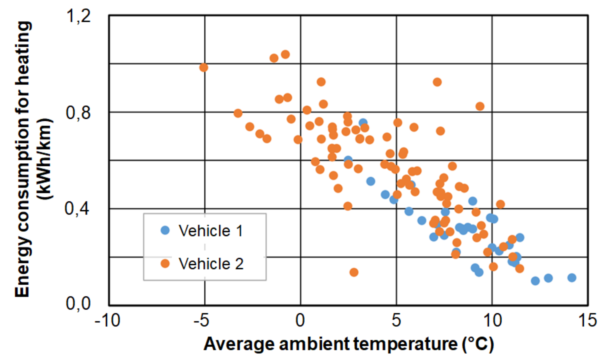
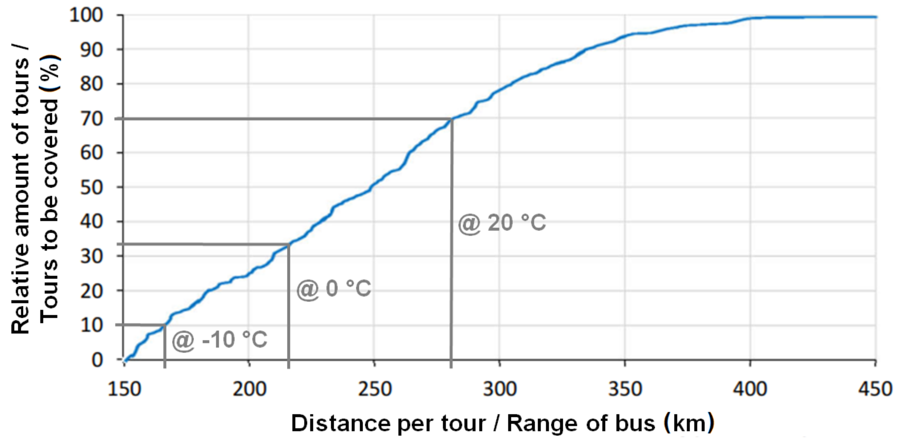
  • Current battery-powered electric buses have drawbacks compared to conventional diesel buses due to their high investment costs and limited range. The investment costs are typically double that of conventional diesel buses. The range is typically limited to below 300 km and becomes even lower when interior heating is required and electric heating systems are used for heating; in such a case, the range can be cut by more than half, which can lead to ranges that prevent electric buses from a year-round use. Because of this, the spread of battery-powered electric buses is currently very low (e.g., only 0.28% of buses within Germany are battery-powered).
  • The described limitations mainly result from the use of costly battery systems, which can easily cost €100,000–200,000, about half of the overall cost of a conventional diesel bus.
  • The charging of a battery-powered electric bus can either be done using “overnight charging,” which requires lower installation costs for the charging systems but requires high-capacity energy-storage systems. The other charging strategy is “opportunity charging,” which leads to higher installation costs for the charging systems but requires low-capacity energy-storage systems. Depending on the charging scenario, either high-energy batteries or high-power batteries should be used.
By utilizing knowledge of the state of the art on battery-powered electric buses, requirements regarding thermal energy storage with metallic phase change material were produced. The main requirements are the following:
  • The storage capacity and performance of a thermal energy storage system with metallic phase change material has to be easily adaptable since it is strongly dependent on the given scenario; storage capacities might vary between 11.7 kWh and 425 kWh, with the installed electric charging power varying between 60.7 kW and 235 kW.
  • The long-term stability of thermal high-performance storage should allow for at least several thousand hours of use. However, maintenance is allowed to reach this, where the ease of maintenance for wearing parts should be considered.
  • Mass and the associated gravimetric energy density is regarded as being more relevant than volume and the associated volumetric energy density since volume for additional components seems to be readily available in a bus; however, mass limits the maximum number of passengers and affects energy consumption for traction. The gravimetric energy density of THS should reach values higher than about 100 Wh/kg for extreme opportunity charging scenarios and values higher than about 180 Wh/kg for extreme overnight charging scenarios to be comparable with a conventional electric heater using electric energy from the traction battery.
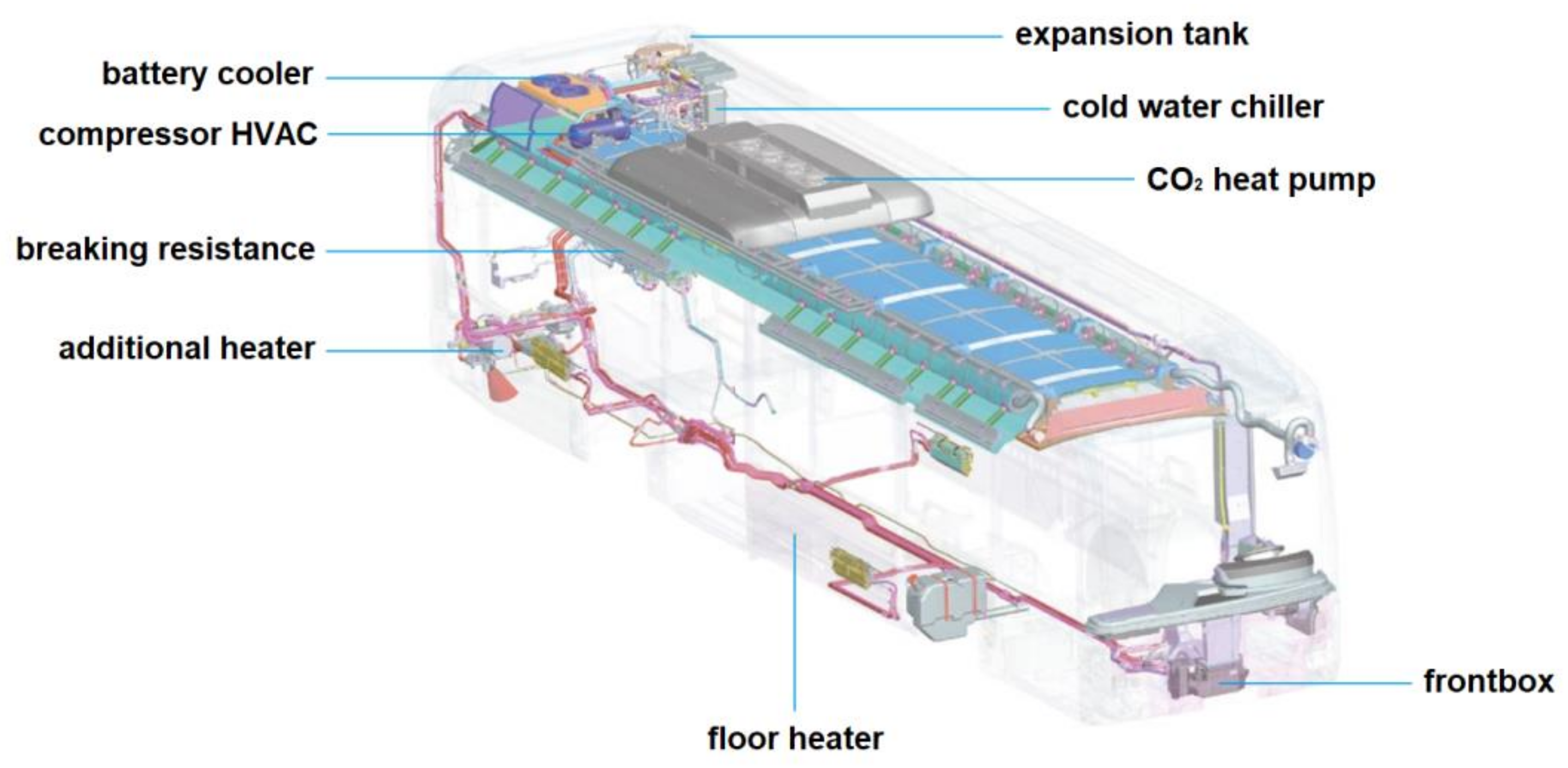
  • The integration into the thermal management architecture could either be done via integration into the airflow provided to the vehicle’s interior or via integration into the liquid cooling circle; however, integration into the liquid cooling circle is regarded as the preferred solution since most of the currently used heating systems are integrated into the liquid cooling circle. Thermal energy storage using metallic phase change materials could simply replace the current heating systems if integration into the liquid cooling circle is possible.
  • The efficiency of a thermal energy storage system using metallic phase change materials should be as high as possible, namely in the range of 90% or more, if possible.
  • The heat supply system of the storage system should ideally be adaptable to a DC intermediate circle with voltages of about 650 to 750 VDC; alternatively, a connection to a 400 VAC level could also be possible.
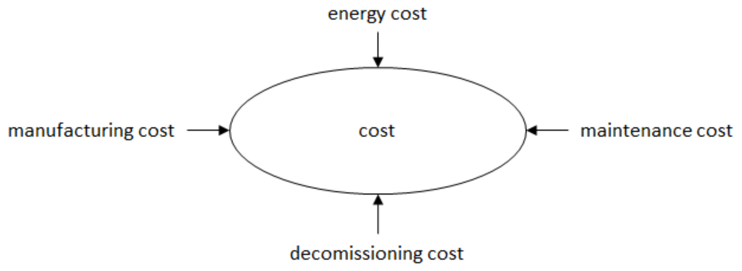
  • The use of thermal energy storage using metallic phase change materials should aim to minimize the overall cost, which is made up of the manufacturing cost, energy cost, maintenance cost, and decommissioning cost.
  • Thermal energy storage using metallic phase change materials should be designed in such a way that no safety issues, especially regarding burning or leakage of liquid metal can occur; also, it should be equipped with safety devices to prevent the system from overheating, for example.
  • Ecological aspects must be considered when designing thermal high-performance storage: if possible, recyclable raw materials, no toxic materials, and no critical raw materials should be used; additionally, the energy costs during manufacturing should be as low as possible.

Author Contributions

The contribution of the author P.V. refers to the Section 2.1.2, Section 2.3.2 and Section 2.3.5. Main contribution was the support of the literature research in these paragraphs. The contribution of the author V.S. refers to the Section 3.2 and Section 3.9. Main contrtibutions were the calculation of the lifetime and the definition of the requirements regarding safety as well as the search for relevant safety regulations. All other contributions come from the author W.K. All authors have read and agreed to the published version of the manuscript.

Funding

This research was funded by the EFRE (Europäischer Fonds für regionale Entwicklung) Leitmarktwettbewerb NRW (Nordrhein-Westfalen) Mobilität.Logistik within the project “Lathe.Go” and by Baden-Württemberg´s Department of Trade and Industry within the project “THS-Bus.”

Conflicts of Interest

The authors declare no conflicts of interest.

References

  1. Kraftfahrt- Bundesamt (KBA). Fahrzeugzulassungen - Bestand an Kraftfahrzeugen nach Umwelt-Merkmalen; Kraftfahrt- Bundesamt (KBA): Flensburg, Germany, 2019. [Google Scholar]
  2. Knote, T. Ansätze zur Standardisierung und Zielkosten für Elektrobusse; Fraunhofer IVI: Dresden, Germany, 2017. [Google Scholar]
  3. Kraft, W.; Jilg, V.; Altstedde, M.K.; Lanz, T.; Vetter, P.; Schwarz, D. Thermal High Performance Storages for use in vehicle applications. In IAV - ETA Tagung; IAV: Berlin, Germany, 2018. [Google Scholar]
  4. Kraft, W. Metallische Latentwärmespeicher als Heizsystem für die Anwendung in Batterieelektrischen PKWs und Bussen; Hochschule für Technik - Seminar Erneuerbare Energien: Karlsruhe, Germany, 2019. [Google Scholar]
  5. Wikipedia. Vorfeldbus. Available online: https://de.wikipedia.org/wiki/Vorfeldbus (accessed on 22 January 2020).
  6. Wikipedia. Stadtbus (Fahrzeug). Available online: https://de.wikipedia.org/wiki/Stadtbus_ (accessed on 22 January 2020).
  7. Wikipedia. Regionalbus. Available online: https://de.wikipedia.org/wiki/Regionalbus (accessed on 22 January 2020).
  8. Wikipedia. Reisebus. Available online: https://de.wikipedia.org/wiki/Reisebus (accessed on 22 January 2020).
  9. Faltenbacher, M.; Eckert, S.; Kupferschmid, S.; Klingenberg, H.; Burkhardt, J.; Schärzel, C.; Kiepsch, M.; Ramme, J.; Knote, T.; Jehle, C.; et al. Marktübersicht Fahrzeuge und Infrastruktur - Programmbegleitforschung Bus; BMVI: Leinfelden-Echterdingen, Germandy, 2019. [Google Scholar]
  10. EvoBus GmbH. Omnibus - Der vollelektrische Mercedes-Benz eCitaro - Special Edition; EvoBus GmbH: Stuttgart, Germany, 2019. [Google Scholar]
  11. Valeo. Thermo AC/DC; Valeo: Gilching, Germany, 2017. [Google Scholar]
  12. Budde-Meiwes, H.; Drillkens, J.; Lunz, B.; Muennix, J.; Rothgang, S.; Kowal, J.; Sauer, D. A review of current automotive battery technology and future prospects. J. Automob. Eng. 2013, 227, 761–776. [Google Scholar] [CrossRef]
  13. Bünnagel, C. Interview mit Sven Schulz, CEO von Akasol; Busplaner.de: Munich, Germany, 2019; pp. 28–31. [Google Scholar]
  14. Batteryuniversity.com. BU-205_ Types of Lithium-ion. Available online: https://batteryuniversity.com/learn/article/types_of_lithium_ion (accessed on 19 February 2020).
  15. Akasol. Akasystem AKM CYC - Ultra-Hochenergietechnologie für Langstreckenanwendungen. Available online: https://www.akasol.com/de/akasystem-akm-cyc (accessed on 19 February 2020).
  16. Akasol. AKASYSTEM AKM POC. Available online: https://www.akasol.com/de/akasystem-akm-poc (accessed on 19 February 2020).
  17. Schwarzer, M. Linienbusse unter Strom. ZEIT ONLINE, Bde. %1 von %2. Available online: https://www.zeit.de/auto/2010-04/linienbusse-strom (accessed on 19 February 2016).
  18. Verkehrsbetriebe Hamburg-Holstein GmbH. Das zweite Leben der Elektrobus Batterien. Available online: https://vhhbus.de/second-life-energiespeicher/ (accessed on 8 April 2020).
  19. Berthold, K. Techno-ökonomische Auslegungsmethodik für die Elektrifizierung urbaner. Busnetze. Dissertation, Karlsruher Schriftenreihe Fahrzeugsystemtechnik, Karlsruhe, Germany, 2019. [Google Scholar]
  20. Cundill, M.; Watts, P. Bus Boarding and Alighting Times; Transport and Road Research Laboratory: Crowthorne, UK, 1973. [Google Scholar]
  21. Sonnakalb, M.; Tegethoff, W.; Försterling, S. CO2 basierte Air-Condition und Heizung für Stadtbusse; Abschlussbericht über ein Entwicklungsprojekt, gefördert unter dem Aktenzeichen Az: 23864 von der Deutschen Bundesstiftung Umwelt: Braunschweig, Germany, 2008. [Google Scholar]
  22. Eberspächer. Eberspächer Wasserheizung Hydronic. 2019. Available online: https://www.eberspaecher.com/produkte/fuel-operated-heaters/produktportfolio/wasserheizungen.html (accessed on 6 March 2019).
  23. UITP Bus Committee. Standardised On-Road Test Cycles - SORT. In Proceedings of the 54th UITP International Congress, London, UK, 20–25 May 2001. [Google Scholar]
  24. Valeo. Werkstatthandbuch Thermo Plus; Valeo: Gilching, Germany, 2018. [Google Scholar]
  25. Valeo. Werkstatt-Handbuch Thermo AC/DC; Valeo: Gilching, Germany, 2018. [Google Scholar]
  26. Bareiß, M.; Vorgerd, D. Thermomanagement für elektrisch angetriebene Stadtbusse. ATZ 2019, 121, 52–55. [Google Scholar] [CrossRef]
  27. Bundesamt für Justiz, Straßenverkehrs-Zulassungs-Ordnung (StVZO) - § 41 Bremsen und Unterlegkeile. 2012. Available online: https://www.gesetze-im-internet.de/stvzo_2012/__41.html (accessed on 7 April 2020).
  28. Jefferies, D.; Ly, T.-A.; Kunith, A.; Göhlich, A. Energiebedarf Verschiedener Klimatisierungssysteme für Elektro-Linienbusse; DKV-Tagung: Dresden, Germany, 2015. [Google Scholar]
  29. Valeo. RevoE; Valeo: Gilching, Germany, 2017. [Google Scholar]
  30. Konvekta, AG. CO2 Wärmepumpe für Elektrobusse; Konvekta: Schwalmstadt, Germany, 2017. [Google Scholar]
  31. Konvekta, AG. UltraLight 500 CO2 Wärmepumpe; Konvekta: Schwalmstadt, Germany, 2018. [Google Scholar]
  32. Wirtschaftswoche, Die Krux mit dem Kältemittel in Auto-Klimaanlagen. 26 Juni 2018. Available online: https://www.wiwo.de/technologie/mobilitaet/umweltbundesamt-warnt-die-krux-mit-dem-kaeltemittel-in-auto-klimaanlagen/22735826.html (accessed on 8 April 2020).
  33. Konvekta, AG. Datenblatt Ultralight 500 EM / 600 EM/700 EM - 2. Gen.; Konvekta: Schwalmstadt, Germany, 2018. [Google Scholar]
  34. Basile, R.; Scheid, H.; Tanke, D.; Moeseler, M.; Häring, R. Beheizungsstrategien für Elektrobusse. In Transport Innovation for Sustainable Cities and Regions (POLIS); Valeo: Brussels, Belgium, 2017. [Google Scholar]
  35. Lee, M.; Lee, H. Steady state and start-up performance charactersitics of air source heat pump for cabin heating in an electric passenger vehicle. Int. J. Refrig. 2016, 69, 232–242. [Google Scholar] [CrossRef]
  36. Miller, W. Laboratory examination and seasonal analysis of frosting and defforsting for an air-to-air heat pump. Ashrae Trans. 1987, 93, 1474–1489. [Google Scholar]
  37. Valeo. Heizsysteme. Available online: https://www.valeo-thermalbus.com/eu_de/Produkte/Heizsysteme (accessed on 17 April 2019).
  38. Valeo. Werkstatt-Handbuch REVO-E; Valeo: Gilching, Germany, 2016. [Google Scholar]
  39. Valeo. Wartungs- und Serviceplan REVO-E Wärmepumpe; Valeo: Gilching, Germany, 2017. [Google Scholar]
  40. Best, P. Entwicklung ener moudlaren und schnellladefähigen Wärmespeicherheizung für vollelektrische Stadtbusse. In 3. Tagung Fahrzeugklimatisierung; Haus der Technik e.V.: Essen, Germany, 2019. [Google Scholar]
  41. Kratzing, R. HEAT2GO - Entwicklung eines schnellladefähigen Latentwärmespeichers für die Beheizung von Elektrobussen; Fraunhofer Institut für Verkehrs- und Infrastruktursysteme IVI: Dresden, Germany, 2017. [Google Scholar]
  42. Grossmann, H. Pkw – Klimatisierung – Physikalische Grundlagen und technische Umsetzung; Springer: Berlin/Heidelberg, Germany, 2013. [Google Scholar]
  43. Climate-Data.org. Klima Winnipeg. Available online: https://de.climate-data.org/nordamerika/kanada/manitoba/winnipeg-982/ (accessed on 5 March 2020).
  44. Climate-Data.org. Klima Astana. Available online: https://de.climate-data.org/asien/kasachstan/astana/astana-491/ (accessed on 5 March 2020).
  45. Climate-Data.org. Klima Las Vegas. Available online: https://de.climate-data.org/nordamerika/vereinigte-staaten-von-amerika/nevada/las-vegas-723/ (accessed on 5 March 2020).
  46. Climate-Data.org. Klima Teheran. Available online: https://de.climate-data.org/asien/iran/teheran/teheran-198/ (accessed on 5 March 2020).
  47. Beekman, R.; van den Hoed, R. Operational demands as determining factor for electric bus charging infrastructure. In Proceedings of the Hybrid and Electric Vehicle Conerence, London, UK, 2 November 2016. [Google Scholar]
  48. Goebelt, R. TÜV Bus-Report 2018; Verband der TÜV e.V.: Berlin, Germany, 2018. [Google Scholar]
  49. Forster, O. Mercedes-Benz eCitaro - Ausfahrt auf leisen Sohlen. Busmagazin 2019, 7–10. [Google Scholar]
  50. Görgler, J. Mercedes-Benz Citaro (Euro 6) - Sparsam unterwegs. Busmagazin 2014, 6–10. [Google Scholar]
  51. EvoBus GmbH. Der Neue eCitaro - Technische Informationen; EvoBus GmbH: Stuttgart, Germany, 2019. [Google Scholar]
  52. EvoBus GmbH. Die Citaro Stadtbusse; EvoBus GmbH: Stuttgart, Germany, 2019. [Google Scholar]
  53. Verband Deutscher Verkehrsunternehmen (VDV). VDV-Mitteilung 2303 - Empfehlung zur Verhinderung von Brandschäden bei Linienbussen; Beka Verlag: Köln, Germany, 2012. [Google Scholar]
  54. Das Europäische Parlament und der Rat der Europäischen Union. Richtlinie 2001/85/EG des europäischen Parlaments und des Rates; Das Europäische Parlament und der Rat der Europäischen Union: Brusseles, Belgium, 2012. [Google Scholar]
  55. Das europäische Parlament und der Rat der europäischen Union. Richtlinie 95/28/EG; Das europäische Parlament und der Rat der europäischen Union: Brusseles, Belgium, 1995. [Google Scholar]
Figure 1. Dependence of the specific heating demand of a 12 m bus on the ambient temperature [2].
Energies 13 03023 g001
Figure 2. The basic setup of the electric architecture of a battery-powered electric bus (without a control system) [2].
Energies 13 03023 g002
Figure 3. The energy density and power density of different electric energy storage systems with a focus on battery technology, plotted as a Ragone diagram [12].
Energies 13 03023 g003
Figure 4. Illustration of the overnight charging strategy with the charging infrastructure located at the bus terminal [2].
Energies 13 03023 g004
Figure 5. Illustration of the overnight charging strategy combined with opportunity charging at a final stop, with the charging infrastructure located at the bus terminal and the final stop [2].
Energies 13 03023 g005
Figure 6. Illustration of the overnight charging strategy combined with opportunity charging at intermediate stops and the final stop, with charging infrastructure located at the bus terminal, at intermediate stops, and the final stop [2].
Energies 13 03023 g006
Figure 7. Detailed view of the assembly of a fuel heater from Eberspächer [22].
Energies 13 03023 g007
Figure 8. Detailed view on the assembly of the electric water heater Thermo AC/DC from Valeo [25].
Energies 13 03023 g008
Figure 9. Comparison of the thermal outputs of heat pumps for bus heating using R134a vs. R744 as the refrigerant [37].
Energies 13 03023 g009
Figure 10. Detailed view of the assembly of the Revo-E heat pump from Valeo [38].
Energies 13 03023 g010
Figure 11. Conceptual design of the thermal energy storage prototype using paraffin wax for heating an electric bus from Fraunhofer and Konvekta [40].
Energies 13 03023 g011
Figure 12. Intended positions of the thermal energy storage modules (red) within the interior of a bus [40].
Energies 13 03023 g012
Figure 13. Thermal management architecture of the EvoBus eCitaro [26]. HVAC: heating, ventilation, and air conditioning.
Energies 13 03023 g013
Figure 14. The distance of daily tours in the German bus transport system that need to be covered as a function of the relative number of tours that can be covered by a bus with the given range [2].
Energies 13 03023 g014
Figure 15. Influencing parameters regarding the requirements for thermal capacity and performance of THS.
Energies 13 03023 g015
Figure 16. Influencing parameters on the requirements for the long-term stability of THS.
Energies 13 03023 g016
Figure 17. Influencing parameters regarding the cost requirements of THS.
Energies 13 03023 g017

