Abstract
The article presents the impact of geological and mining factors on the stability of room excavations in the Legnica-Głogów Copper District (LGOM) in Poland. In underground mining, the primary task of bolting of mining excavations is to ensure their stability as an essential condition of work safety. Appreciating the role and importance of the rock bolting in Polish ore mining; rock bolt load sensors were designed, manufactured and tested under laboratory conditions. The purpose of the research was to characterize the sensors and determine the elastic range of the bearing plate, which are an integral part of the sensor. The sensors have been verified in industrial conditions. The tests were carried out in the underground copper ore mine in Poland. Three rooms in the exploitation field were selected for testing, where exploitation was carried out at a depth of 809–820 m below the ground surface with the application of room and pillar with roof deflection and maintaining the central part of the field. The exploitation field included 60 rooms and pillars. The effectiveness of the mechanical load sensor of the expansion rock bolt support has been experimentally confirmed. Based on mine research, it was found that the largest increases in the load of the rock bolting, vertical stress and convergence occur in the middle of the mining field.
1. Introduction
One of the conditions for safe exploitation of ore deposits is the ability to maintain the specific geometrical parameters of a room excavation for a certain period of time. In this case, the stability of the room is determined by the limit span of the roof. In ore mining, there are cases that at spans smaller than limit, due to structural disorders, there are symptoms of local instability in the form of roof falls or stratification of the roof. The direct causes of local instability may be excessive concentrations of tensile stress in the roof, compressive in the side wall, as well as local change in strength parameters of the rock mass [1]. The potential for activation of local instability can be estimated based on observation of the mining crew. Particularly in the case of dynamic loads resulting from blasting works or natural tremors, the crew is required to tear off hazardous rocks before commencing work in a given shift, or secure with a support those solids that cannot be broken. Based on observation and research in industrial conditions, various rock mass classifications are developed to assess local instability. An example would be the RFRI fall risk assessment index [2], which lists 10 categories of roof defects. It should be stated that RFRI index does not take into account technological factors related to the mining system. In terms of maintenance of the excavation, rock mass discontinuities such as fissures and stratification play a special role. One method for estimating the impact of these parameters is the RDi classification [3] enabling estimation of the drilling rate based on rock texture and other geotechnical features of the rock mass. Among the assessments of the behaviour of underground excavations in ore mines, in particular in the Legnica-Głogów Copper District (LGOM) in Poland, noteworthy classifications are based on the analysis of measurement results in the exploitation field. Korzeniowski [4] proposed six parameters, such as distance from the exploitation front line; convergence rate and convergence along the exploitation front line; convergence on the goaf side; number of key blocks; compressive strength of roof rocks, based on which he determined four categories of roof falls.
The issue of rock bolting and rock mass monitoring work is of great interest to both mining plant and many research centers. Prediction of the magnitudes of the in situ and induced stresses is a vital part of the underground excavation design process and monitoring [5]. For underground mining, new sensor designs are created for extreme operating conditions, in particular in mining conditions, but also in tunneling. In underground excavations, the quality of rock bolt support operation and the behaviour of the rock mass around the excavations are assessed by means of rock bolts based on the following systems: strain gauges [6,7,8,9,10]; vibrating wire [11,12,13]; optical fibers [14,15,16]; cavimeter method [17], and also using non-destructive testing methods, using the phenomenon of wave propagation (reflexion method) along the tested element [18,19,20,21,22,23]. Another direction of research is associated with the use of mechanical load sensors, whose common feature is the relatively simple structure and low cost of implementation. When determining the load on the rock bolting, the speed and simplicity of measurement, access to the sensor, accuracy of reading and measurement should be taken into account. In addition, the possibility of sensor damage due to a technological process or the occurrence of natural hazards must be taken into consideration. Economically, production and technical rights of production must be kept, which preclude the use of load sensors on each of the bolts. The use of single load sensors of the rock bolt support in the event of limit states allows for taking appropriate measures to protect the mining crew against sudden loss of excavation stability. A simple and quick way to measure the load on the rock bolt support are mechanical sensors in the form of:
- Sleeve with variable diameter, which under loads becomes subject to yield and crush. A characteristic feature of the sleeve is the variable geometry of the three walls along the entire length. During the yielding process, its length is reduced to approximately 25 mm. On the basis of the crushing positive zones in the sleeve, the observer qualifies the load acting on the bolt support [24];
- Measuring cylinder, which is covered with metallic enamel. Load measurement is based on the observation of the enamel surface area loss from the measuring cylinder. The main advantage of this method is the rapid observation of changes in the sensor coating, but it should be stated that the assessment of the load by the person monitoring the condition of the bolt support is subjective [25];
- Slide out the colored pin from the measuring sleeve inside the sensor equipped with disc springs. Under load, the disc springs are compressed and the bolt extends from the measuring sleeve. Load identification is based on the appearance, extension of the pin with the red segment. Knowing the pitch of the nut thread and the number of turns needed to determine the level between the red and black ranges on the measuring pin, the load can be qualitatively estimated [26];
- Fall of measuring cylinders from a dynamometric bearing plate, which consists of two cylinders that move relative to each other due to the effect of compressive load. The thickness of each measuring ring is selected according to the load-deformation characteristics of the elastic element. After sliding and falling off individual measuring rings of known thickness, their number is visually determined and the values of axial force loading the bolt are determined indirectly [27,28].
The efficiency of making the bolt support in the conditions of LGOM mines, most often includes activities related to checking the correctness of its installation in the excavation. In the case of expansion bolts, the tightening torque of the bolt nut is checked with a torque wrench and their load capacity is tested by pull out tests. For the conditions of underground mining of copper ore deposits in the LGOM, optimal methods for monitoring the rock bolt support and the rock mass are still being sought.
In the rock mass classifications for the LGOM region, parameters that take into account the load on the bolt support are missing. Currently, mechanical sensor designs lack solutions that consist of two bearing plates and two disc springs, which differ in the rigidity of the construction materials and whose load increase can be quickly assessed by manual measurements. Therefore, in this study laboratory tests have been performed on the characterization of a new mechanical load sensor for the rock bolt support. In addition, the sensor was used in industrial conditions in the underground copper ore mine in LGOM in Poland, in which a room and pillar method with roof deflection and maintaining the central part of mining field is used. The results of tests in situ in relation to the measurements of the convergence of the excavation and the increase of vertical stresses in the inter-room pillars confirm that the sensor can be an indicator of the rock bolt support load, contributing to an increase in the level of safety in the room excavations.
2. Factors Affecting the Stability of Room Excavations in LGOM Mines
2.1. Impact of Shocks
Currently, in underground mining, the main factor causing dynamic loads on the mining support is the occurrence of rock mass shocks that reach to a given mining excavation [29,30,31,32]. Exploitation of copper ore deposits in the LGOM area is associated with rock mass shocks, which very often determine the stability of the room excavations. Mining shocks can cause a rock burst, leading to loss of excavation functionality. At present, shocks are distinguished for the LGOM region, which are characterized according to the classification presented in Table 1.

Table 1.
Energy classification of rock mass shocks [33].
The impact of mining shocks on the room excavations with seismic energy E ≥ 105 J, forces the use of various rock burst prevention measures related, among others, to the introduction of the so-called waiting times. Re-execution of works in the exploitation field after a rock mass shocks with energy E ≥ 105 J may take place after the set time of waiting and carrying out the inspection of excavations in the danger area. The danger area includes mining excavations located at a distance of:
- up to 100 m from the epicenter of a shock with seismic energy 105 J ≤ E <106 J or the place of its effects;
- up to 150 m from the epicenter of a shock with seismic energy 105 J ≤ E <106 J or the place where its effects occur;
- up to 200 m from the epicenter of the shock with seismic energy E ≥ 107 J or the place of its effects;
- in the event of a rock burst or stress relief (regardless of the seismic energy) the danger area includes the operational front.
Geomechanical and technological shocks occurring in copper ore mines are one of the most important problems related to the loss of excavation stability [34,35]. Additional dynamic loads negatively affect not only the functionality of the room excavation, but also the condition of the rock bolts. Based on mine observations, it was found that the largest changes occur in the case of very stratified or irregularly built roofs. In most cases, there are no visible changes in the roof and bolt support after the shocks occur. The effects of roof destruction appear relatively rarely and usually are visible only after a certain period of time. The impact of rock mass shocks on the excavation condition is manifested in the form of: falling off rock lumps from the side walls of excavations (local dynamic rock outbursts from the side walls of the excavation); falling of rocks around bearing plates; falling out of small rock fragments between the bolts, causing the process of further destruction of the roof; the formation of fissures between bolted layers; breaks (fissures) in the roof layers (Figure 1a); local roof falls of the roof layers about 2 m high (Figure 1b); lifting the floor of the room. However, the impact of rock mass tremors on the rock bolt support is manifested in the form of: breaking of the bolt when the roof rocks fall, only a few dozen centimeters thick, whose weight per bolt is disproportionately small compared to its carrying capacity (Figure 1c); a decrease in the pre-tension of the expansion bolts from 30% to 50% and the sliding of the bolts from the hole (Figure 1d).
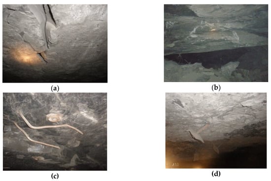
Figure 1.
Impact of rock mass tremors on the condition of the room excavation and the rock bolt support: (a) Fissure in the roof; (b) Local roof falls; (c) Break in the bolt material continuity; (d) Sliding of the bolts from the hole
2.2. Geological Factors
The copper ore deposits mined by KGHM in the Legnica-Głógów Copper District in Poland are located in the southwest part of the Fore-Sudetic Monocline, close to the northern boundary of the Fore-Sudetic Block. The monocline is composed of Upper Permian to Cretaceous sediments, and it is a part of the Permian sedimentary basin [36]. The monocline, in the area where the copper ore is found, is formed of sedimentary rocks belonging to the Permian and Triassic eras, dipping at the angle of a few degrees. The Permian-Triassic formations of the monocline are discordantly covered by Tertiary and Quaternary sediments. The copper ore deposit of the Fore-Sudetic monocline dipping to the NE, similarly to the layers creating the monocline, is classified as of the stratified type in the sedimentary rocks (sediment-hosted copper ore deposit) [37]. The deposit is formed of accumulations of copper sulphides, occuring in the white and grey-white sandstones of Red Footwall Sandstone (Rotliegendes) and Upper Permian (Zechstein), and in the cupriferous shales and carbonate rocks (mainly dolomites) of the Upper Permian (Zechstein) [37]. The detailed distribution of copper ore deposits in the Legnica-Głogów Copper District were presented in publications by Oszczepalski et al. [38] and Skrzypkowski et al. [34]. The thickness of the main roof rocks in the LGOM mines reaches over 200 m and consists mainly of anhydrite, limestone and dolomite with a strength that is 7 to 10 times greater than the strength of floor rocks (Figure 2a). The main roof rocks in the LGOM mines consist of a sedimentary sequence, over 200 m in thickness, of sub-horizontal carbonate strata (both dolomite and limestone). Wherein, the dolomites reach about 20 meters, and above is an anhydrite strata. Sedimentary layers of the anhydrite and gypsum are parallel to the bedding. These parameters, together with the depth of deposit deposits, lithological structure and rich tectonics (faults, fissures), mean that the deposit is in specific loading conditions during exploitation [39,40]. The impact of rock lithology on rock strength is manifested in the fact that the more strong, resilient and non-deformable rocks are, the more rock mass is usually prone to generating tremors [41]. The mining forehead consists of three types of rocks: limestone and dolomites, copper-bearing shales and sandstones. The so-called shale zones, which are characterized by the lack of deformation of the copper-bearing shale layer, have a significant impact on the strength properties of deposit rocks. Instead, durable, irregular sandstone lenses with clay-anhydrite binder appear [42]. The factor that determines the structural image of the deposit and creates difficulties in its access and exploitation are faults (Figure 2b). Often exploitation filed is cut by several normal faults with dominant dip direction. Nearly 60% of the faults have throwings below 1 m, about 35% of the faults in the range from 1 m to 10 m and only slightly more than 5% of the dislocations have an amplitude above 10 m [40]. The increase in seismic hazard in the vicinity of faults results from the existence of discontinuities facilitating the displacement of rock layers. The ability to activate a fault depends on the conditions on the fault surface. The greater the angle of inclination of the fault plane, the lower the friction force on the fault surface, and the greater the possibility of violating its balance [43,44]. A characteristic feature of copper ore deposits in the LGOM area is the presence of carbonate rocks in the roof, which are represented by dolomitic marlstones, which are fragile rocks, which are hardly resistant to mechanical factors; streaked dolomites are easily destroyed; limestone dolomites resistant to mechanical factors and dolomitic limestone which is also a compact and strong rock. Carbonate rocks have a layer structure (Figure 2c,d).
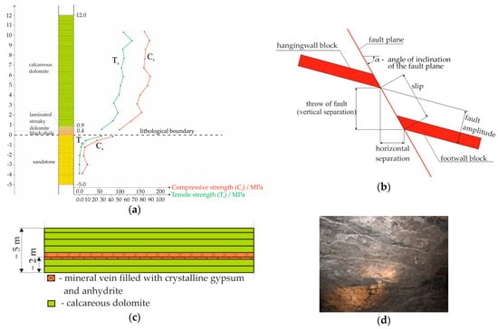
Figure 2.
Geological factors affecting on the stability of a room excavation: (a) Variability of rock compressive and tensile strength; (b) Fault parameters; (c) Stratification of roof layers; (d) Stratification roof with visible horizontal white layers of gypsum and anhydrite.
In 2001 Kidybiński [45] analyzed 264 endoscopic holes from three LGOM mines in order to assess the plate structure of roof rocks. As a result of the research, a method of classifying endoscopic profiles was proposed. In more than 50% of the tested holes, only horizontal gaps were encountered (i.e., there were no areas of structural weakness that were not gaps). Oblique and vertical gaps were encountered in more than 5% of the holes. However, in 50 holes mineral overgrowth was found, which are potential surfaces for breaking the roof, among them calcite and gypsum veins could be distinguished. Based on the profile of the endoscopic hole, usually 5.0 m in length, it was proposed to introduce an index of stratification of roof rocks. The indicator can be useful for uniform numerical assessment of the layered structure of the roof. The selection of the rock bolt support for mining excavations in the underground mines in the LGOM area is based on the recognition of geological and mining conditions, consisting in determining the roof class, in accordance with the instructions of KGHM Polska Miedź S.A. [46] determining the value of geomechanical parameters of roof rocks. Classification of roof rocks (Table 2) was based on the hierarchy of importance of parameters (Table 3), which determine the stability of mining excavation roofs.
Table 2.
Classification of roofs in copper ore mines due to the selection of rock bolt support.
Table 3.
Parameters characterizing roof rocks in the aspect of rock bolt support selection.
Table 3 shows that the excavation stability is mainly determined by the areas of reduced mass density up to 70%, and to a small extent rock strength parameters up to 30%. After determining the roof class, the rock bolt support (spacing and length) is selected. The bolt support is selected for the entire period of operation of excavations in the mining field, before proceeding to the cutting phase.
The width of excavations carried out at the cutting phase, maintained at the phase of developed exploitation and during the liquidation phase depends on: the roof class, the exploitation method used, mechanization process, the height of the forehead rooms and the minimum inclination angle of the side walls.
The selection of the rock bolt assumes the maximal width of excavations achieved in the developed field exploitation phase. Additionally, based on the correction factor (K), the corrected roof class in a given exploitation field is determined:
where K—correction factor; SG—total point value (summary grade); w1—operational weakening factor of the roof for rock bolts of a certain length and w2—rock mass reinforcement factor.
As a result of the introduction of the correction factor, the grade of the roof may be reduced by a class, especially in thick-layer roofs with high tensile strength and relatively low tectonic involvement. A direct consequence of the reclassification, while maintaining the assumed length of the bolts and the width of the selected space opening, will be the necessity to thicken the bolting scheme and reduce the maximal width of excavations in the developed field exploitation phase. An alternative might be to extend the bolts or reduce the opening width. In the cases of new fields and fields with existing roof falls, the bolt support selection is verified. In addition, ongoing monitoring of excavation stability includes visual observation and random checks of bolt support performance parameters. In justified cases, in particular improper cooperation of the bolt support with the rock mass or the implementation of new types of support, geomechanical tests of rocks, stratification of roof rocks, roof decreasing and bearing capacity of the bolt are carried out.
2.3. Mining Factors
The basic condition for safe and economical exploitation of deposits is proper management of the roof, including determining its full carrying capacity. Due to the way the roof is managed in the LOGM underground mines, there are methods with roof deflection and automatic caving as well as methods with roof protection (hydraulic backfilling and rock fill).The use of room and pillar method with roof deflection consists in cutting the deposit with the arrangement of rooms and leaving inter-room pillars of such dimensions that on the front of the works leads to the destruction of the structure of the pillars and their work in a post-failure state (Figure 3a). This is particularly important in rock burst hazard conditions, as the rock mass in the post-failure state has very little capacity to accumulate elastic energy. That is why proper selection of shape and technological dimensions is a fundamental technological method for combating rock bursts. The pillars work on post-failure (decreasing) stress-strain characteristics, characterized by high yieldable and allow the roof to deflect. A stratified and relaxed rock block breaks off the roof over the entire mining field, which loads the technological pillars [35]. The final phase in the field of exploitation is the cutting of inter-room pillars (Figure 3b) to the minimal dimensions (Figure 3c). This process is followed by a roof caving in the depths of the goaf.
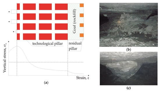
Figure 3.
Room and pillar method with roof deflection: (a) Scheme of the exploitation and an ideological stress-strain diagram; (b) Pillar before cutting; (c) Pillar after cutting.
As the mining front advances, the technological pillars change their shapes, the rooms expand significantly and the roof area per unit of active pillar cross-section increases. Under these conditions, stratification or roof falls may occur. In a horizontally stratified rock mass, it can be assumed that in the first phase of driving a room excavation (Figure 4a), the behaviour of the room is similar to the work of a beam evenly loaded and restrained at both ends. The safe excavation width at this stage of operation is determined by ensuring moderate deflection of the roof layers. The rock mass, which is stratified, is characterized by surfaces of reduced density, therefore, with the passage of time, the phenomenon of separation of the direct roof layers from stiffer layers of the main roof may occur. As the mining front moves, the roof beam begins to crush and sag (Figure 4b). A pressure vault forms in the relaxed zone of the roof. Further widening of the room excavation results in a three-hinged arch in the direct roof (Figure 4c). Exceeding the maximal width of the excavation leads to the destruction of the three-hinged arch and the fall of rocks into the excavation [47].
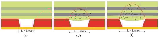
Figure 4.
Behaviour of the room excavation roof as a result of moving the mining front: (a) Direct roof in the bed cutting phase; (b) Fissured and bending roof beam; (c) Formation of a three-hinged arch; L—room width; Lmax—maximal room width; 1—pressure vault; 2—relief stress zone.
Assessing the stability of the room in the room excavation, it can be assumed that rock layers bolted to the height equal to the length of the base rock bolt support are treated as: continuous; discontinuous, two-span; discontinuous, three-span and multi-span. As a result of the passage of the room excavation from the cutting phase to the developed phase of exploitation, the load capacity of the roof changes as its maximum span increases. A continuous layer can transform from a continuous to discontinuous two-span, three-span or multi-span (Figure 5a–c). As research shows [48] there is no simple relationship between the threat of roof rock collapse in the developed mining zone and the nominal load-bearing capacity. The difference results from the actual tensile strength of the anchor rod and their nominal load capacity.
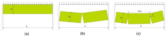
Figure 5.
Safety factors for roof layers: (a) Continuous; (b) Two-span discontinuous; (c) Three-span discontinuous; d—layer thickness, L—layer span; ms—length of the middle block; T—axial force.
From Figure 5a, it follows that the decisive influence on the roof stability in the case of a continuous layer has the tensile strength of the rocks in the extreme lower sides. Safety factor for continuous layer (B1) can be calculated according to the following formula:
where Ts—tensile strength of rocks and σt—maximal tensile strength.
Maximal deflection (f) of the roof can be calculated according to the following formula:
where γ—unit weight; L—layer span; E—Young’s modulus and d—layer thickness.
In the case of a discontinuous double-span layer, the compressive strength of rocks in the lower and upper hings plays a decisive role. Safety factor (B2) for this case can be calculated according to the following formula:
where Cs—compressive strength and σc—maximal compressive strength.
For the three-span discontinuous layer, safety factor (B3) for this case can be calculated according to the following formula:
where m, a, c—coefficients and r—block slenderness (r = L/d).
In bolted roofs, it is particularly dangerous to crush hings and slip on the surfaces of vertical or oblique fissures. The possibility of destruction of a discontinuous rock layer by buckling is small, as it concerns loose layers of rocks of very low thickness [48].
3. Laboratory Tests of the Rock Bolt Support Load Sensor Characterization
The tests were carried out in the bolting laboratory of the Department of Mining Engineering and Work Safety at the AGH University of Science and Technology in Krakow. Mechanical load sensors for the rock bolt support have been designed and manufactured in laboratory conditions (Figure 6a). The sensor consists of two profiled bearing plates, two disk springs, three mounting screws and three holes in the bearing plate (Figure 6b).
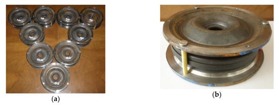
Figure 6.
Mechanical force sensors designed for the rock bolt support: (a) General view; (b) Detailed view.
Construction materials of different stiffness have been specially selected so that under the influence of load first there is incomplete compression of the springs, and then plastic deformation of the bearing plate from the side of the bolt rod flange. Plastic deformation of the bearing plate is possible due to the difference in the diameter of the holes in the bearing plate and in disc springs (Table 4).
Table 4.
Technical parameters of disc springs and bearing plates of a mechanical force sensor.
In the tests an expansion rock bolts with a length of 1830 mm, which was installed in the concrete block. were used. The expansion head with a length of 93 mm and a diameter of 36 mm (Figure 7) was expanded in the bolt hole with a diameter of 38 mm, using a torque wrench. Measurement of the mechanical deformation of the force sensor (change in distance between two bearing plates) was made through three holes in the bearing plate using an electronic caliper (Figure 8).
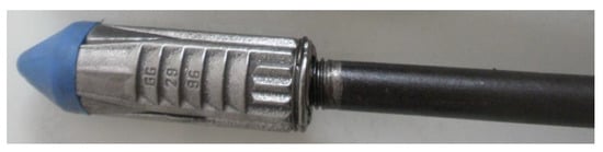
Figure 7.
Bolt rod with an expansion head.
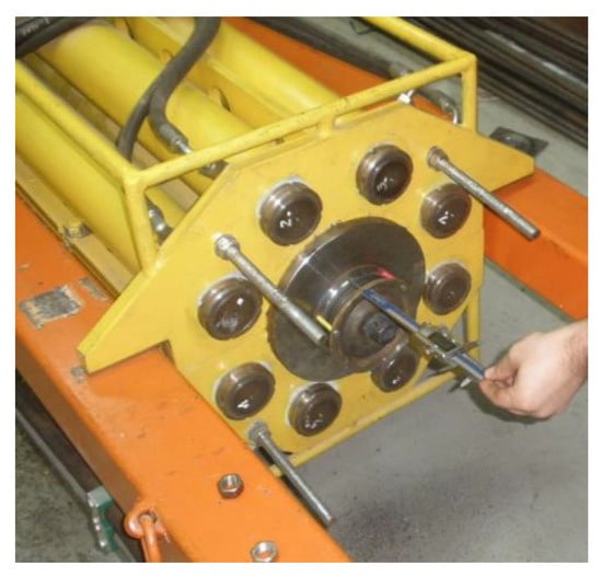
Figure 8.
Sensor calibration.
Simultaneously with the measurement of the mechanical deformation of the force sensor, load measurements of the entire bolt support were carried out. Four strain gauges force sensors were used for the measurement, which were connected to the measuring amplifier type QAUNTUM MX840A (HBM, Spectris plc, Darmstadt, Germany). The measurement results were monitored on an ongoing basis in the CatmanEasy software (HBM, Spectris plc, Darmstadt, Germany). The tests were carried out under static load. The load rate was 0.5 kN/s. The tests assumed a hold time of 120 s, which was used to read the measurements from the caliper. Each time after a 10 kN load increase, the hold time followed. Rock bolts equipped with force sensors have been tested five times. The results of sensor calibration measurements are presented in Figure 9a–e.
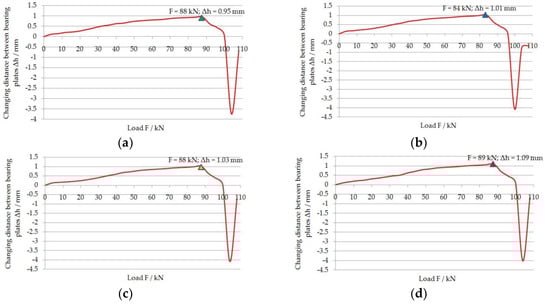
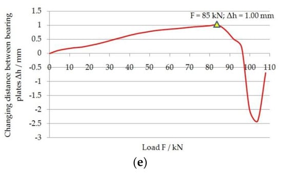
Figure 9.
Calibration of the mechanical force sensor of the expansion rock bolt: (a) Bolt no 1; (b) Bolt no 2; (c) Bolt no 3; (d) Bolt no 4; (e) Bolt no 5.
Based on the sensor calibration results, it can be concluded that the spring range of the bearing plates is in the range from 84 kN to 89 kN. This range corresponded to the elastic deformation of the bearing plates in the range from 0.95 mm to 1.09 mm. After exceeding these values, plastic bearing plate deformed inside the disc spring opening, which can be observed by a negative result on the axis of change in distance between two bearing plates. The minimal load-bearing capacity of the rock bolt in ore mining should be 100 kN and the extension of the bolt should not exceed 10 mm. The obtained results of the force sensor calibrations are sufficient in terms of the required load-bearing capacity and deformability for the underground conditions of the LGOM mines, therefore it was decided to use mechanical force sensors in industrial conditions.
4. Industrial Tests
Industrial tests were carried out in the underground copper ore mine “Polkowice Sieroszowice”, belonging to KGHM Polish Copper S.A. in the LGOM area. Exploration field B was selected for testing, where mining was carried out at a depth of 809–820 m below the ground surface, with a room-pillar method with roof deflection and maintaining the central part of the mining field. The research focused on measuring the load of the expansion rock bolt support, vertical convergence and determining the increase in vertical stress. Three rooms, numbers 3, 26 and 57, in which tests were performed twice a week for two months were selected to assess the behaviour of the room excavation during progressing operation (Figure 10). In exploitation field B, the width of the pillar along the strike was 6 m and length 8 m. On the other hand, the width of the room at the roof was 6 m, and at the bottom 5 m. The height of excavations in the cutting phase depended on the thickness of the exploited deposit and the operating requirements of working self-propelled machines and was up to 4.5 m. The room height ranged from 1.8 m to 2.6 m. The minimal opening size of the mining front was equal to the sum of the width of two strips and the length of two rows of pillars, as well as the section with rooms into the ore face. The maximal width of the front opening was 112 m. The width of the maintaining the central part of the mining field included six pillars (Figure 10). As the exploitation front progresses, the technological pillars from the last row before the goafs were taken, cut into smaller ones, depending on the degree of their disintegration. Supporting pillars were taken to residual dimensions with a minimal area of 7.4 m2, and then left in goafs, where they fulfilled the role of supports yielding the curvature of the bending floor layers. The space between the residual pillars was filled with the use of rock fill, obtained from mining of ore deposits.
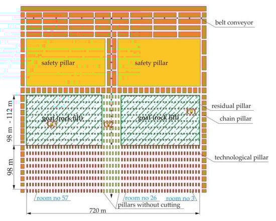
Figure 10.
Room and pillar method with roof deflection and maintaining the central part of the mining field.
In exploitation field B occurs, three lithological types of ore:
- black shale and laminated streaky dolomite, black to dark gray, concise, with varying thickness from 0.2 m to 0.6 m;
- dolomite streaked light gray, light beige, concise, with a microcrystalline structure, with fine veins of light sulphates, contains a small admixture of clay, weakly fissured, with varying thickness from 0.4 m to 1.4 m;
- dolomite calcareous gray, dark gray, beige, concise, with a microcrystalline structure, locally cavernous, formed as a set of layers with a clear layer division in packages from 0.2 m to 0.6 m, corrugated and horizontal lamination dominates, visible sulphate veins, stylolite seams occur of course compatible with carbonate lamination only locally with vertical course.
The thickness of the balance ore deposit ranges from 1.0 m to 1.85 m (1.35 m on average) with a capacity of 123 kg/m2 [49]. The ore deposit extends towards NW-SE, 1–4° fall on NE. The rock mass is poorly tectonically involved. Several normal faults were found with discharges from 1.0 m to 4.5 m, with dip angles from 80° to 90° and the course of W-E and SW-NE. They form characteristic backstage systems, often cascading.
There are more or less vertical and oblique fissures with the main directions SW-NE. The ore deposit is located at a depth of 809 to 820 m below the ground surface. Mining excavations - rooms are carried out in the bottom layer of the basic dolomite and in the gray sandstone roof (Figure 11).
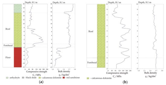
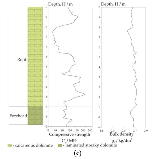
Figure 11.
Geotechnical profiles of the deposit in mining field B: (a) Drillhole G1; (b) Drillhole G2; (c) Drillhole G3.
In order to identify the geological conditions of the ore deposit, in particular in terms of the selection of the rock bolt support in the area of mining field B, geotechnical holes were made: G1 (crossing of room no 3 and belt no 3); G2, (crossing of room no 32 and belt no 5) and G3 (crossing of room no 52 and belt no 5), (Figure 10), from which the cores were taken, on the basis of which structural, strength and deformation parameters were determined [49,50] (Table 5).
Table 5.
Geomechanical properties of rocks in the exploitation field B.
4.1. Measurement of Bolt Support Load and Vertical Convergence
In selected exploitation rooms: 3, 26 and 57, an additional three expansion rock bolts with new mechanical force sensors were installed in the excavation roof (Figure 12a). In the industrial tests, the same bolt support as in laboratory tests were used. The additional bolt support was 1830 mm long and was installed in the hole by means of a 36 mm expansion head. In the roof of the room excavations holes with a diameter 38 mm were drilled. In each room, three sensors were installed. The load on the bolt support was determined indirectly by measuring the appropriate distances of the sensor reference points using an electronic caliper with a reading accuracy of up to 0.01 mm (Figure 12b). This measurement was carried out through three holes in the force sensor bearing plate (Figure 6b). Then, using calibration curves (Figure 9a–e), axial force values were determined. Simultaneously with the measurement of the load on the bolt support, vertical convergence was measured (Figure 13). In the test a laser rangefinder, which had a measurement accuracy of up to 1 mm and a range of up to 80 m was used. As the base of measurement, the end of the bolt rod in the roof and the benchmarks built in the bottom of the excavation, between which the measurement was taken, was adopted (Figure 12a). In each of the test rooms: 3, 26 and 57) three measurements were taken, twice a week. The test was conducted over a period of two months. The results of measurements of the rock bolt support load as a function of distance from the operational face and vertical convergence are presented in Figure 14a–c.
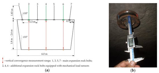
Figure 12.
Measurement of the rock bolt load in the exploitation room: (a) Arrangement of sensors; (b) Indirect load measurement.
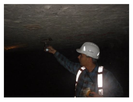
Figure 13.
Vertical convergence measurement.
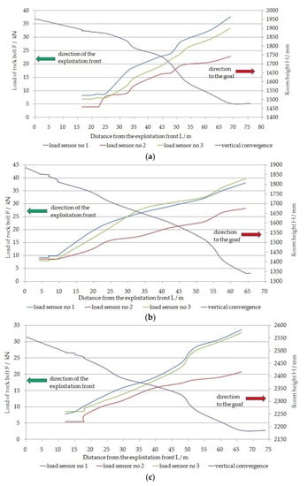
Figure 14.
Load of rock bolts and convergence in the exploitation room: (a) Room number 3; (b) Room number 26; (c) Room number 57.
4.2. Measurement of Vertical Stress Increase
To estimate vertical stress in three inter-room pillars (Figure 15a), Geokon 4300EX [51] vibrating wire sensors were installed (Figure 15b-c), whose range of compression is 70 MPa and tensile 3 MPa. The length of the opening in the inter-room pillar for the sensor was 3 m. The sensors were located in the pillars between rooms: 3 and 4; 25 and 26 and 56 and 57. Strain of the ring, caused by a change in stress in the rock mass, was measured by the vibrations of the wire attached to the inner diameter of the ring. The change in the resonant frequency of the vibrating wire was read using a GK-403 recorder (Figure 15d). The test results are presented in Figure 16.
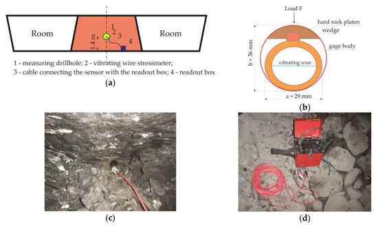
Figure 15.
Measurement of stress increase in the inter-room pillar: (a) Scheme of sensor location in the pillar; (b) A 4300EX sensor placed into the pillar; (c) Dimensions of the sensor; (d) GK-403 readout box.
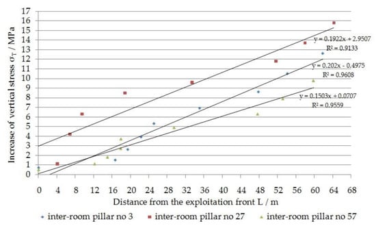
Figure 16.
Value of vertical stress increase in inter-chamber pillars.
After making measurements using a vertical stress sensor and reading the value from the recorder, the state of stress in the inter-room pillar was determined by applying the following formula [51]:
where σT—the stress change corrected for temperature/MPa; R0—initial reading/digit and R1—subsequent reading/digit:
where F—frequency/Hz; T0—initial temperature/°C; T1—subsequent temperature/°C and G—sensitivity factor.
5. Discussion
The load on the rock bolt support was measured on the same day as the measurement of vertical convergence and increase of vertical stress. The measurement was made along with the progressing exploitation front in the room and pillar mining method with roof deflection and the maintaining the central part of the mining field over a period of two months with a frequency of twice a week. During this time, the exploitation front moved by 75 m. The measuring sensors used to measure the load on the rock bolts were arranged along the belts in such a way that it was possible to measure the appropriate values in three characteristic places of the exploitation field, namely in the central part (room number 26) and in two boundary rooms: on the so-called left wing (room number 3) and right wing (room number 57). In the period covered by the measurements, changes in the load of the rock bolt were found in the range from 33.2 kN to 37.6 kN in room number 3. The maximal values were recorded at a distance of 68 m from the operational face. In room number 26, located in the middle of the mining field, the load on the rock bolt ranged from 38.1 kN to 39.6 kN. Maximal values were recorded at a distance of 64.3 m from the operational face. For room number 57 the load ranged from 32.7 kN to 33.6 kN. Maximal values were recorded at a distance of 66.5 m from the operational face. Taking into account the average rate of load increase of the expansion rock bolt, it can be stated that the highest growth rate corresponds to the maximal absolute value achieved and in room number 26 is 0.63 kN/day. Accordingly, in room number 3, the average load was 0.56 kN/day, and in room number 57, the average load was 0.53 kN/day. The average daily loads of the bolt support in the central part of the mining field are higher by 11.11% and 15.87%, respectively, compared to the boundary rooms: 3 and 57.
In the period covered by the measurements, changes in vertical convergence were found in the range of 370 mm in the right part of the field (room number 57), 478 mm in the left wing (room number 3), up to 545 mm in the middle part, i.e., in room number 26. Taking into account the average the rate of convergence increase, it can be stated that the highest growth rate corresponds to the maximal absolute value achieved and in room number 26, it is 8.4 mm/day. Correspondingly, in room number 3 the average rate was 6.4 mm/day, and in room number 57 the average value of convergence rate was 4.9 mm/day. The average convergence rate in the central part of the mining field is higher by 23.81% and 41.66%, respectively, compared to the boundary rooms: 3 and 57.
The values of vertical stress increase were measured in three inter-room pillars numbers: 3, 27 and 57 simultaneously with the measurement of the load of the rock bolt and vertical convergence.
The maximal increase in vertical stress in the inter-pillar (σT = 15.8 MPa) occurred in the central part of the mining field, i.e., between rooms 25 and 26; 64 m from the mining face. Then the convergence was 545 mm, with the maximal load of the rock bolt. For the two boundary rooms of the mining field, i.e., room number 3 and room number 57, the maximal values of vertical stress increase were 12.6 MPa and 9.8 MPa, respectively. Then the convergence for rooms: 3 and 57 was 475 mm and 370 mm, respectively, at the maximal load of the rock bolt. For the two-month period, the average weekly increase in vertical stress for rooms: 3, 26 and 57 was 1.47 MPa/week; 1.84 MPa/week; 1.14 MPa/week, respectively. The average weekly increase in vertical stress in the middle of the field is greater by 20.11% and 38.04%, respectively, compared to the boundary rooms: 3 and 57.
6. Conclusions
Based on the laboratory and industrial tests, it can be stated that:
- load measurement of the expansion rock bolt support in industrial conditions can be carried out manually and does not require an internal or external power source;
- up to the value of 90 kN, the bearing plates exhibit elastic characteristics, after exceeding this range, the plastic deformation of the bearing plates occurs, which deforms inside the spring disc; this is a very important feature that allows a very fast and direct assessment of the rock bolt support load (at such a load level, the swollen bolt rod or nut does not draw out beyond the plane of the bearing plate, it is hidden inside the sensor);
- for the underground exploitation of copper ore deposits in the LGOM area, in which the room and pillar method with roof deflection and maintaining the central part of the mining field is used, it was found that the largest load of the rock bolt support, increases vertical stress and the value of vertical convergence occurs in the central part of the exploitation field.
In mining excavations, in which an independent rock bolts support is used, there is a risk of unforeseen falling of rock blocks into the excavation. The specially designed load sensor of the rock bolt can be an excellent meter and signaling device that will significantly increase awareness and safety.
Funding
This paper was prepared as part of AGH’s scientific subsidy, under number: 16.16.100.215.
Conflicts of Interest
The author wishes to confirm that there are no known conflicts of interest associated with this publication and there has been no significant financial support for this work that could have influenced its outcome.
References
- Skrzypkowski, K. The Influence of Room and Pillar Method Geometry on the Deposit Utilization Rate and Rock Bolt Load. Energies 2019, 12, 4770. [Google Scholar] [CrossRef]
- Iannacchione, A.T.; Prosser, L.J.; Esterhuizen, G.; Bajpayee, T.S. Technique to assess hazards in underground stone mines: The roof-fall-risk-index (RFRI). Min. Eng. 2007, 59, 49–57. [Google Scholar]
- Hoseinie, S.H.; Aghababaei, H.; Pourrahimian, Y. Development of a new classification system for assessing of rock mass drillability index (RDi). Int. J. Rock Mech. Min. 2008, 45, 1–10. [Google Scholar] [CrossRef]
- Korzeniowski, W. Evaluation of State of Underground Gateroads and Rooms Based on Empirical Research Methods; AGH University of Science and Technology: Kraków, Poland, 2006; p. 138. [Google Scholar]
- Sepehri, M.; Apel, D.; Szymanski, J. Full three-dimensional finite element analysis of the stress redistribution in mine structural pillar. J. Powder Metall. Min. 2013, 3, 1–7. [Google Scholar] [CrossRef]
- Mitri, H. Evaluation of Rock Support Performance Through Instrumentation and Monitoring of Bolt Axial Load. In Proceedings of the 11th Underground Coal Operators’ Conference, Wollongong, Australia, 10–11 February 2011; University of Wollongong and the Australian Institute and Metallurgy: Wollongong, Australia, 2011; pp. 136–140. [Google Scholar]
- Korzeniowski, W.; Skrzypkowski, K.; Zagórski, K. Reinforcement of Underground Excavation with Expansion Shell Rock Bolt Equipped with Deformable Component. Stud. Geotech. Mech. 2017, 39, 39–52. [Google Scholar] [CrossRef]
- Li, Y.; Liu, C. Experimental study on the shear behavior of fully grouted bolts. Constr. Build Mater. 2019, 223, 1123–1134. [Google Scholar] [CrossRef]
- Waclawik, P.; Ptacek, J.; Konicek, P.; Kukutsch, R.; Nemcik, J. Stress-state monitoring of coal pillars during room and pillar extraction. J. Sustain. Min. 2016, 15, 49–56. [Google Scholar] [CrossRef]
- Waclawik, P.; Snuparek, R.; Kukutsch, R. Rock Bolting at the Room and Pillar Method at Great Depths. Procedia Eng. 2017, 191, 575–582. [Google Scholar] [CrossRef]
- Guo, X.; Wang, B.; Ma, Z.; Wang, Z. Testing Mechanical Properties of Rock Bolt under Different Supports Using Fiber Bragg Grating Technology. Sensors 2019, 19, 4098. [Google Scholar] [CrossRef] [PubMed]
- Geokon. Available online: https://www.geokon.com/4910 (accessed on 20 May 2020).
- SHM System. Available online: http://www.shmsystem.pl (accessed on 21 May 2020).
- Vlachopoulos, N.; Cruz, D.; Forbes, B. Utilizing a novel fiber optic technology to capture the axial responses of fully grouted rock bolts. J. Rock Mech. Geotech. Eng. 2018, 10, 222–235. [Google Scholar] [CrossRef]
- Forbes, B.; Vlachopoulos, N.; Diederichs, M.S.; Aubertin, J. Augmenting the in-situ rock bolt pull test with distributed optical fiber strain sensing. Int. J. Rock Mech. Min. 2018, 126, 104202. [Google Scholar] [CrossRef]
- Gong, H.; Kizil, M.S.; Chen, Z.; Amanzadeh, M.; Yang, B.; Aminossadati, S.M. Advances in fibre optic based geotechnical monitoring systems for underground excavations. Int. J. Min. Sci. Technol. 2019, 29, 229–238. [Google Scholar] [CrossRef]
- Gustafsson, L.K.K.A. Sensor techniques to monitor installation and status of rock bolts. In Proceedings of the Eighth International Symposium on Ground Support in Mining and Underground Construction: “Ground Support 2016”, Kulturens Hus, Luleå, Sweden, 12–14 September 2016; pp. 1–13. [Google Scholar]
- Ivanović, A.; Neilson, R.D. Non-destructive testing of rock bolts for estimating total bolt length. Int. J. Rock Mech. Min. 2013, 64, 36–43. [Google Scholar] [CrossRef]
- Song, G.; Li, W.; Wang, B.; Ho, S.C.M. A Review of Rock Bolt Monitoring Using Smart Sensors. Sensors 2017, 17, 776. [Google Scholar] [CrossRef] [PubMed]
- Luo, M.; Li, W.; Wang, J.; Wang, N.; Chen, X.; Song, G. Development of a Novel Guided Wave Generation System Using a Giant Magnetostrictive Actuator for Nondestructive Evaluation. Sensors 2018, 18, 779. [Google Scholar] [CrossRef] [PubMed]
- Fuławka, K.; Mertuszka, P.; Pytel, W. Monitoring of the stability of underground workings in Polish copper mines conditions. In E3S Web of Conferences 2018; EDP Sciences: Les Ulis, France, 2018; Volume 29, pp. 1–14. [Google Scholar] [CrossRef]
- Skrzypkowski, K.; Korzeniowski, W.; Zagórski, K.; Dominik, K.; Lalik, K. Fast, non-destructive measurement of roof-bolt loads. Stud. Geotech. Mech. 2019, 41, 93–101. [Google Scholar] [CrossRef]
- Bačić, M.; Kovačević, M.S.; Jurić Kaćunić, D. Non-Destructive Evaluation of Rock Bolt Grouting Quality by Analysis of Its Natural Frequencies. Materials 2020, 13, 282. [Google Scholar] [CrossRef] [PubMed]
- VandeKraats, J.D.; Watson, S.O. Direct Laboratory Tensile Testing of Select Yielding Rock Bolt Systems; Westinghouse Electric Corp.: Carlsbad, NM, USA, 1996; pp. 321–332. [Google Scholar]
- Leonhardt, J.C. Visual Recognition of the Load of Roof—Bolts by an Indicator. In Proceedings of the 20th International Conference on Gronund Control in Mining, Morgantown, WV, USA, 7–9 August 2001; Lakeview Resort and Conference Center: Morgantown, WV, USA, 2001; pp. 362–366. [Google Scholar]
- Friesen, G.R. Rockbolt Monitor; Patent and Trademark Office: Washington, DC, USA, 1993; pp. 1–7. [Google Scholar]
- Korzeniowki, W.; Skrzypkowski, K.; Herezy, Ł.; Kulik, M.; Zagórski, K. Method for Measuring the Anchor Loading and the Dynamometric Anchor Washer; Polish Patent: Warsaw, Poland, 2017; pp. 1–4. [Google Scholar]
- Korzeniowki, W.; Skrzypkowski, K.; Herezy, Ł. Remote, non-electric rock-bolt loading force indicator WK-2/8 for mining excavation. Bull. Miner. Energy Econ. Res. Inst. Pol. Acad. Sci. 2018, 103, 53–64. [Google Scholar] [CrossRef]
- Butra, J.; Kudełko, J. Rockburst hazard evaluation and prevention methods in Polish copper mines. Cuprum 2011, 61, 5–20. [Google Scholar]
- Pytel, W.; Świtoń, J.; Wójcik, A. The effect of mining face’s direction on the observed seismic activity. Int. J. Coal. Sci. Technol. 2016, 3, 322–329. [Google Scholar] [CrossRef][Green Version]
- Burtan, Z. The influence of regional geological settings on the seismic hazard level in copper mines in the Legnica-Głogów Copper Belt Area (Poland). In E3S Web of Conferences, 2017; EDP Sciences: Les Ulis, France, 2017; Volume 24, p. 01004. [Google Scholar] [CrossRef]
- Skrzypkowski, K. A New Design of Support for Burst-Prone Rock Mass in Underground ore Mining. In E3S Web Conferences; EDP Sciences: Les Ulis, France, 2018; Volume 71, p. 6. [Google Scholar] [CrossRef]
- KGHM Polska Miedź, S.A. Rules of conduct after rock bursts, stress relief and strong tremors in the mines of KGHM Polska Miedź S.A.; KGHM: Lubin, Poland, 2005. [Google Scholar]
- Skrzypkowski, K.; Korzeniowski, W.; Zagórski, K.; Zagórska, A. Adjustment of the Yielding System of Mechanical Rock Bolts for Room and Pillar Mining Method in Stratified Rock Mass. Energies 2020, 13, 2082. [Google Scholar] [CrossRef]
- Skrzypkowski, K.; Korzeniowski, W.; Zagórski, K.; Zagórska, A. Modified Rock Bolt Support for Mining Method with Controlled Roof Bending. Energies 2020, 13, 1868. [Google Scholar] [CrossRef]
- Awdankiewicz, M.; Pieczonka, J.; Piestrzyński, A.; Sawlowicz, Z. Late Palaeozoic post orogenic volcanism in the Sudetes Mts. and the Kupferschiefer-type Cu-Ag ore deposits in the Fore-Sudetic Monocline. Acta Mineral. Petrogr. Field Guide Ser. 2010, 18, 1–34. [Google Scholar]
- KGHM Polska Miedź, S.A. Report on the Mining Assest of KGHM Polska Miedź S.A. Located within the Legnica-Głogów Copper Belt Area; KGHM: Lubin, Poland, 2012; p. 15. [Google Scholar]
- Oszczepalski, S.; Speczik, S.; Zieliński, K.; Chmielewski, A. The Kupferschiefer Deposits and Prospects in SW Poland: Past, Present and Future. Minerals 2019, 9, 592. [Google Scholar] [CrossRef]
- Butra, J. Technological aspects of copper ores mining in KGHM Polska Miedź S.A. mines aimed to the bumps hazard control. Cuprum 2003, 1, 63–96. [Google Scholar]
- Małkowski, P.; Ostrowski, Ł.; Bachanek, P. Modelling the Small Throw Fault Effect on the Stability of a Mining Roadway and Its Verification by In Situ Investigation. Energies 2017, 10, 2082. [Google Scholar] [CrossRef]
- Goszcz, A. Selected Problems of Seismic Hazard and Rock Burst Hazard in Underground Mines; Mineral and Energy Economy Research Institute of the Polish Academy of Sciences: Kraków, Poland, 2004; p. 81. [Google Scholar]
- Goszcz, A. Elements of Rock Mechanics and Rockbursts in Polish Coal and Copper Mines; Mineral and Energy Economy Research Institute of the Polish Academy of Sciences: Kraków, Poland, 1999; p. 83. [Google Scholar]
- Burtan, Z.; Zorychta, A.; Cieślik, J.; Chlebowski, D. Influence of mining operating conditions on fault behavior. Arch. Min. Sci. 2014, 59, 691–704. [Google Scholar] [CrossRef]
- Tajduś, A.; Cała, M.; Tajduś, K. Seismicity and rock burst hazard assessment in fault zones: A case study. Arch. Min. Sci. 2018, 63, 747–765. [Google Scholar] [CrossRef]
- Kidybiński, A. The effect of blasting work on stability of rock-bolted roofs in the copper mines. Mon. Mag. State Min. Auth. 2001, 9, 5–16. [Google Scholar]
- KGHM Polska Miedź S.A. Instructions for Determining the Geomechanical Parameters of Roof Rocks in Terms of Determining the Roof Classes in Copper Ore Mines in LGOM, When Selecting the Rock Bolt Support; KGHM Polska Miedź S.A.: Lubin, Poland, 2002. [Google Scholar]
- Adler, L.; Sun, M. Ground Control in Bedded Formations; Virginia Polytechnic Institute: Blacksburg, VA, USA, 1968; p. 266. [Google Scholar]
- Kidybiński, A. Chamber working roof load bearing capacity in developed exploitation phase of LGOM (Legnica-Głogów Copper Region) deposit. Min. Rev. 2002, 7–8, 30–35. [Google Scholar]
- KGHM Polska Miedź, S.A. Geological Documentation of Exploitation Field B at KGHM Polska Miedź S.A.; “Polkowice-Sieroszowice” Mine: Kaźmierzów, Poland, 2011. [Google Scholar]
- Fabich, S.; Flasiński, W.; Jóźwik, M.; Maćków, B.; Nitek, D. Geomechanical testing of rocks. In Part 1. KGHM CUPRUM Spółka z o.o.; Research and Development Center: Wrocław, Poland, 2012. [Google Scholar]
- Geokon. Instruction Manual Vibrating Wire Stressmeter 4300 Series (EX, BX, NX); Geokon Inc.: Lebanon, NH, USA, 2004; p. 9. [Google Scholar]
© 2020 by the author. Licensee MDPI, Basel, Switzerland. This article is an open access article distributed under the terms and conditions of the Creative Commons Attribution (CC BY) license (http://creativecommons.org/licenses/by/4.0/).