Article

An Energy Management System-Based Control Strategy for DC Microgrids with Dual Energy Storage Systems

by
Subarto Kumar Ghosh
1,
Tushar Kanti Roy
2,
Md Abu Hanif Pramanik
3,
Ajay Krishno Sarkar
1 and
Md. Apel Mahmud
4,*
1
Department of Electrical & Electronic Engineering, Rajshahi University of Engineering & Technology, Rajshahi 6204, Bangladesh
2
Department of Electronics & Telecommunication Engineering, Rajshahi University of Engineering & Technology, Rajshahi 6204, Bangladesh
3
Department of Electrical & Computer Engineering, Rajshahi University of Engineering & Technology, Rajshahi 6204, Bangladesh
4
School of Engineering, Deakin University, Geelong, VIC 3216, Australia
*
Author to whom correspondence should be addressed.
Energies 2020, 13(11), 2992; https://doi.org/10.3390/en13112992
Submission received: 17 April 2020 / Revised: 3 June 2020 / Accepted: 4 June 2020 / Published: 10 June 2020
(This article belongs to the Section D: Energy Storage and Application)

Abstract

:
In this work, a control strategy is developed for different components in DC microgrids where set points for all controllers are determined from an energy management system (EMS). The proposed EMS-based control scheme is developed for DC microgrids with solar photovoltaic (PV) systems as the primary generation units along with energy storage systems. In this work, the concept of dual energy storage systems (DESSs) is used, which includes a battery energy storage system (BESS) and supercapacitor (SC). The main feature of this DESS is to improve the dynamic performance of DC microgrids during severe transients appearing from changes in load demands as well as in the output power from solar PV units. Furthermore, the proposed EMS-based control scheme aims to enhance the lifetime of the BESS in DC microgrids with DESSs and voltage stability as compared to the same without SCs. The proposed EMS-based control strategy uses proportional-integral (PI) controllers to regulate the switching control actions for different converters within the DC microgrid based on the decision obtained from the EMS in order to achieve the desired control objectives. The performance of the proposed scheme was analyzed through simulation results in terms of improving the voltage stability, maintaining the power balance, and enhancing the lifetime of BESSs within a DC microgrid framework incorporated with the DESS. The simulations are carried out in the MATLAB/SIMULINK simulation platform and compared with a similar approach having only a single energy storage system, i.e., the BESS.

1. Introduction

DC microgrids have been gain popularity over AC microgrids due to several benefits such as the utilization of power generation from solar photovoltaic (PV) systems with fewer power conversion stages, no additional requirements for frequency as well as reactive power control, etc. [1,2,3,4]. Hence, the control structure becomes simple for converters in DC microgrids and there are low power losses, which improve the overall efficiency of the system. Furthermore, some specialized applications, e.g., railway signaling systems and base transceiver systems (BTSs) in telecommunication applications, use DC power for which it is feasible to have DC microgrids with solar PV systems (as it directly generates DC power) along with energy storage systems (ESSs).
ESSs in DC microgrids are used to store the excess energy from solar PV systems and release this energy when there is no power generation from solar PV systems. In this way, ESSs maintain the proper power balance and voltage stability within DC microgrid to tackle the intermittency of solar PV systems and variations in the load demand [5,6,7]. Different types of ESSs, e.g., batteries, hydrogen storage systems for fuel cells, supercapacitors (SCs), etc., are used to optimally manage the power in DC microgrids and each of these ESSs has its own distinct features [8,9,10]. Battery ESSs (BESSs) have widely different applications including DC microgrids due to the maturity of the technology and their low costs as compared to other ESSs [11,12]. However, BESSs exhibit low power density for which the dynamic response is much slower, and, sometimes, they are unable to provide ancillary services to DC microgrids with fast changes in load demands and variations in the power generation from the solar PV units. This means that DC microgrids experience power disruptions under severe transient events. The slow dynamic response characteristics can be overcome by employing ESSs having high power density, e.g., SCs which are able to provide fast dynamic responses. However, these SCs are more expensive as compared to BESSs, and, therefore, it is important to have a trade-off between the performance and cost. This trade-off can be obtained by combing both BESSs and SCs, i.e., by forming a dual energy storage system (DESS). The DESS in DC microgrids with a proper energy management system (EMS)-based control strategy is essential to appropriately coordinate the charging and discharging of both BESSs and SCs in order to maintain the power balance as well as the voltage stability.
Different components in DC microgrids are generally controlled by using centralized control schemes to ensure the appropriate power sharing for maintaining power balance and voltage stability [13,14,15,16]. These centralized controllers centrally control ESSs for storing and releasing desired energy without having a proper EMS; thus, these controllers cannot appropriately coordinate the power sharing. Furthermore, there is an issue of the common point failure in these centralized control structures. Distributed controllers are employed in [17,18,19,20,21] for DC microgrids which overcome some limitations (e.g., the common point failure) of the centralized controllers. These distributed controllers perfectly maintain the power balance and stability of the common DC-bus voltage with slight variations in the output power generation and load demands as these are designed based on the static models of different components in DC microgrids. These static models do not capture the dynamic characteristics of solar PV systems and ESSs that are experienced during the practical operation of DC microgrids. It is worth noting that the dynamic of the common DC-bus voltage plays a key role to ensure the power balance within the DC microgrid. This dynamic is indirectly related with the states of different components (e.g., solar PV systems and ESSs) in microgrids. Hence, the control actions for converters with these components need to be regulated in such a way that the desired voltage is obtained at the common DC-bus. This can only be achieved if ESSs are appropriately charged or discharged. An improved distributed control scheme for DC microgrids with multiple ESS is presented in [22] to enhance the common DC-bus voltage regulation and keep the state-of-charge (SoC) within the safe operating region. A modified structure of DC microgrids grids is considered in [23,24,25] where the detailed dynamical models of solar PV systems and BESSs are used without any SC. However, all these controllers are designed based on the simplified models of different components in DC microgrids without having an EMS, even though it is a key component effectively making the power sharing decisions. Furthermore, all these works have used only BESSs for storing or releasing energy in order to maintain the power balance and voltage stability.
BESSs cannot instantaneously supply power under abrupt changes in load demands and the output power of solar PV systems. Furthermore, the continuous charging and discharging of BESSs regulate the SoC over a wide range which significantly reduce the lifetime and efficiency of the battery [26]. This problem of charging or discharging can be resolved through the DESS, which seems for attractive for DC microgrids due to its fast dynamic responses and cost-effectiveness [27,28,29,30,31,32]. Although these studies have shown the improvement in dynamic performance with hybrid ESSs (HESSs), the dynamic characteristics of SCs in conjunction with the BESS (which provide cost-effective solutions) have not been investigated. Furthermore, these applications of HESSs do not consider EMS-based control strategies for the optimum utilization of ESSs in DC microgrids.
This paper focuses on designing an EMS-based control strategy for DC microgrids with DESSs. Here, BESSs and SCs are combined together to form DESSs. A microgrid structure with a solar PV unit, DESS, and DC load is considered to employ the proposed EMS-based control scheme. The detailed dynamical models of each component are developed to demonstrate the importance of the dynamic of the common DC-bus voltage and its relationship with other properties of the system. Furthermore, the relationship between the dynamic of the common DC-bus voltage and power balance is revealed in this work and it demonstrates the application of a PI controller for different components to ensure the power balance. The reference values for regulating the power for different components (especially, for the solar PV unit and DESS) are determined from the EMS in order to regulate the control actions. The performance of the proposed EMS-based control scheme was evaluated under different operating conditions of the DC microgrid in order to maintain the voltage stability and power balance along with enhancing the lifetime of the BESS. Simulation results clearly demonstrate the advantages of the DESS over a single storage system under different operating conditions of the DC microgrid.

2. DC Microgrid Configuration and Model

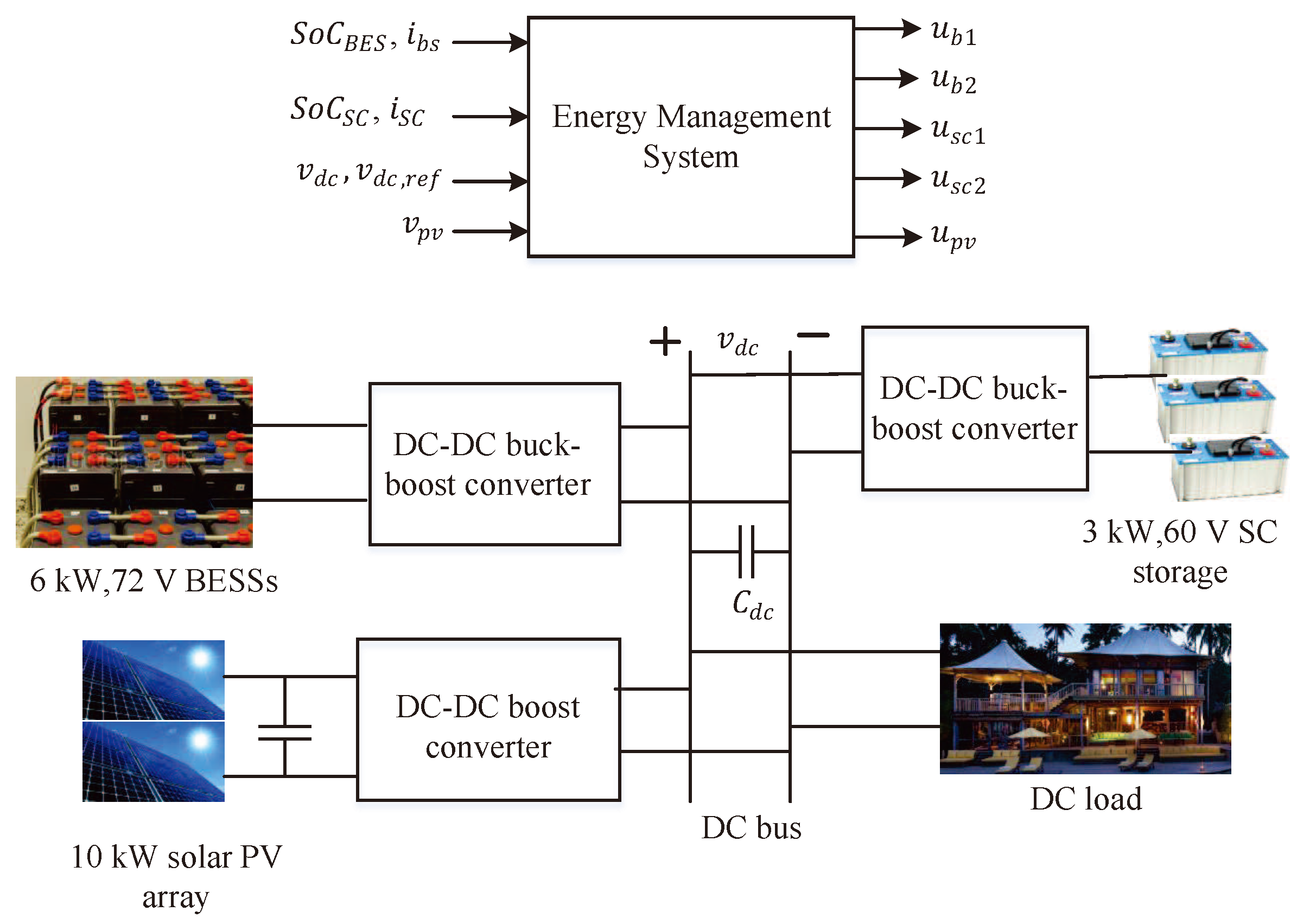
The microgrid shown in Figure 1 is used in this work to develop the proposed EMS-based control strategy. The key components of this DC microgrid are a solar PV array, a BESS, a SC, and DC loads. All these components are interconnected through a common DC-bus within the DC microgrid in conjunction with the DC–DC converter. In this microgrid configuration, the solar PV array is considered as the main source for supplying power to the load and it is assumed that the maximum power from the PV array is extracted using an incremental conductance approach. The BESS and SC within this microgrid are used as the dual energy storage system (DESS) for balancing the power under different operating conditions, i.e., variations in the output power the solar PV unit due to its intermittent characteristics and changes in load demands. The overall power flow control among different components within this DC microgrid is managed through the proposed EMS and the control actions of different entities are regulated based on the decisions from the EMS.

2.1. Overview of Solar PV Array and Its Modeling

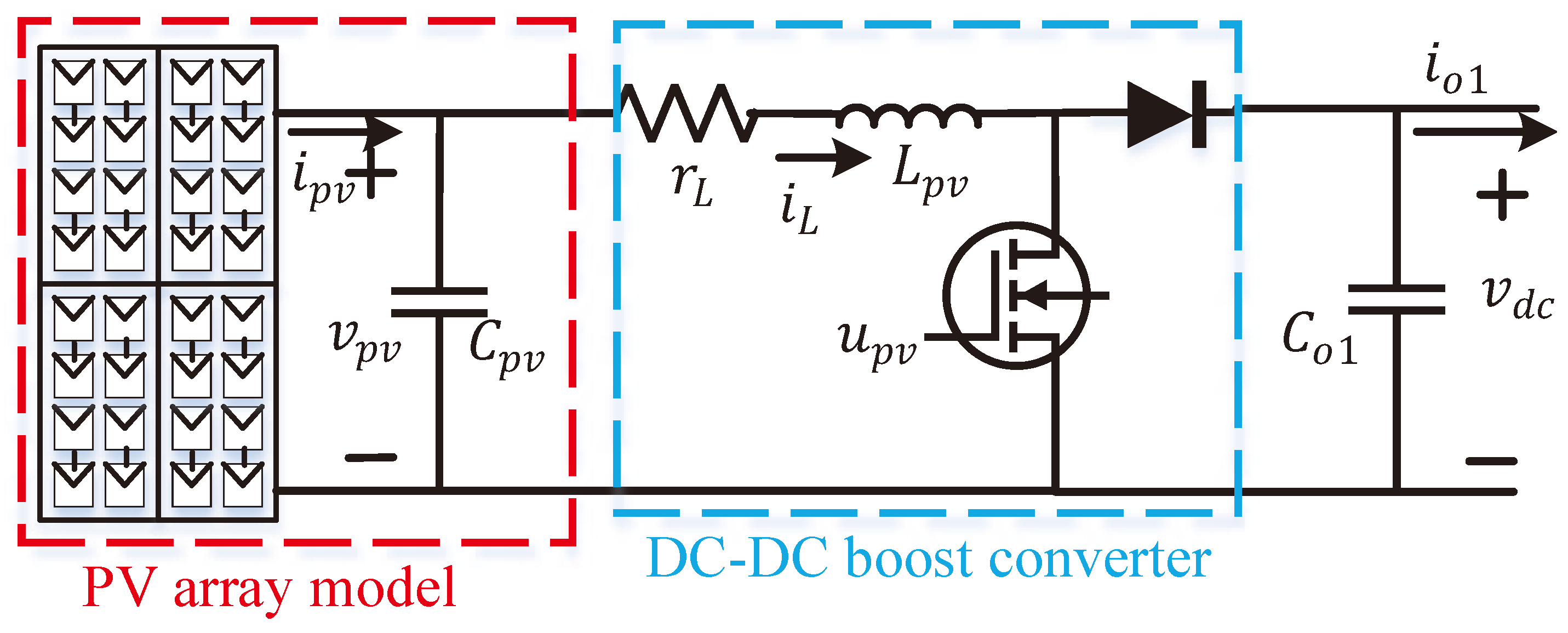
The solar array is the series-parallel combination of solar cells in order to achieve the desired output power and voltage as the output power of a single solar cell is very small. The internal structure of each solar cell includes some diodes. There are high levels of uncertainty in the sunlight as well as in the environmental temperature. The solar PV system exhibits highly nonlinear electrical characteristics during the energy conversion process.The lifetime of the solar PV system is much lower than traditional power generation systems; thus, it is essential to extract the maximum power from the PV system in order to achieve more benefits and the extraction of the maximum power under varying environmental conditions (e.g., solar irradiation and temperature) is a challenging task. In this work, an incremental conductance (IC)-based maximum power point tracking (MPPT) algorithm is employed for extracting maximum power from the solar PV system. A DC–DC boost converter is used for the DC microgrid in Figure 1 as the output voltage of the solar PV array is lower than the common DC-bus voltage and the connection of a solar PV array with a DC–DC boost converter is shown in Figure 2. The dynamics of a solar PV system with a DC–DC boost converter employed in a DC microgrid can be explained with the set of following equations [23]:
C p v d v p v d t = i p v i L
L p v d i L d t = [ v p v r L i L ( 1 u p v ) v d c ]
C 01 d v d c d t = ( 1 u p v ) i L i 01
where v p v is the voltage of PV farms, i p v is the current of PV farms, v d c is the voltage at DC-bus, i L is the current through the converter’s inductor, i 01 is the output current of the converter, u p v is the control input of the converter, C p v is an input capacitor of PV farms, L p v is an inductor of a converter, r L is an inductor’s internal resistance, and C 01 is the output capacitor of a boost converter.

2.2. Overview of Battery Energy Storage System and Its Modeling

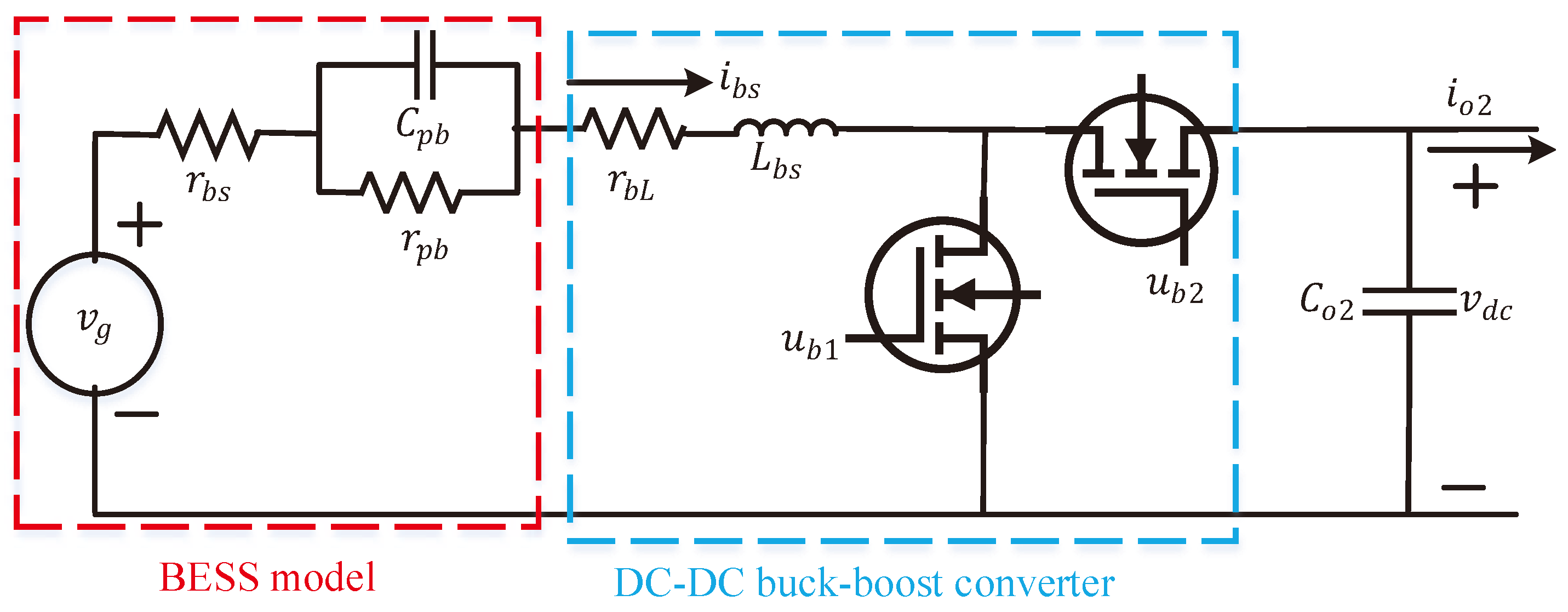
BESSs play a key role for maintaining a constant common mode DC-bus voltage in DC microgrid while enhancing the power balance with the intermittent characteristics of the solar power generation. Figure 3 shows an electrical equivalent circuit of a BESS including a bidirectional DC–DC buck-boost converter. BESSs compensate the surplus and deficit energy of DC microgrids and the EMS determines the amount of the surplus/deficit. Based on the surplus/deficit energy information from the EMS, the switching control actions are regulated in such a way that the power balance is ensured for the DC microgrid. The BESS needs to be charged or discharged based on the surplus or deficit energy conditions; it is essential to consider the state-of-charge (SoC) while regulating the switching control actions for the bidirectional DC–DC converter. Hence, the control scheme for the BESS needs to be designed based on the DC-bus voltage and the state-of-charge (SoC) information.
During the operation of the DC microgrid, the SoC of the BESS is limited to S o C B E S , m a x and S o C B E S , m i n , which limit the maximum discharging and charging currents of the BESS in between i b s , m a x and i b s , m i n in order to protect the BESS from over-discharging or over-charging. This situation can be described by the conditions in Equations (4) and (5).
S o C B E S , m i n S o C B E S ( t ) S o C B E S , m a x
i b s , m i n i b s ( t ) i b s , m a x
where S o C B E S is the state of charge of BESSs and i b s is the current of BESSs.
The dynamics of the BESS with a bidirectional converter can be described using the set of following equations [23]:
C p b d v p b d t = i b s v p b r p b
L b s d i b s d t = ( r b L + r b s ) i b s + ( 1 u b s ) v d c v p b + v g
C 02 d v d c d t = ( 1 u b s ) i b s i 02
where v g is the control voltage of BESSs; i b s is the current of BESSs; v p b is the voltage across the parallel RC network of BESSs; i 02 is the output current of a bidirectional converter; v d c is the voltage at DC-bus; r b s and C p b are the resistance and capacitance of the parallel RC network of BESSs, respectively; C 02 is the output capacitor of a bidirectional converter; r b L is the inductor’s internal resistance; and u b s is the control input of a bidirectional converter of BESSs.

2.3. Overview of Supercapacitor Storage System and Its Modeling

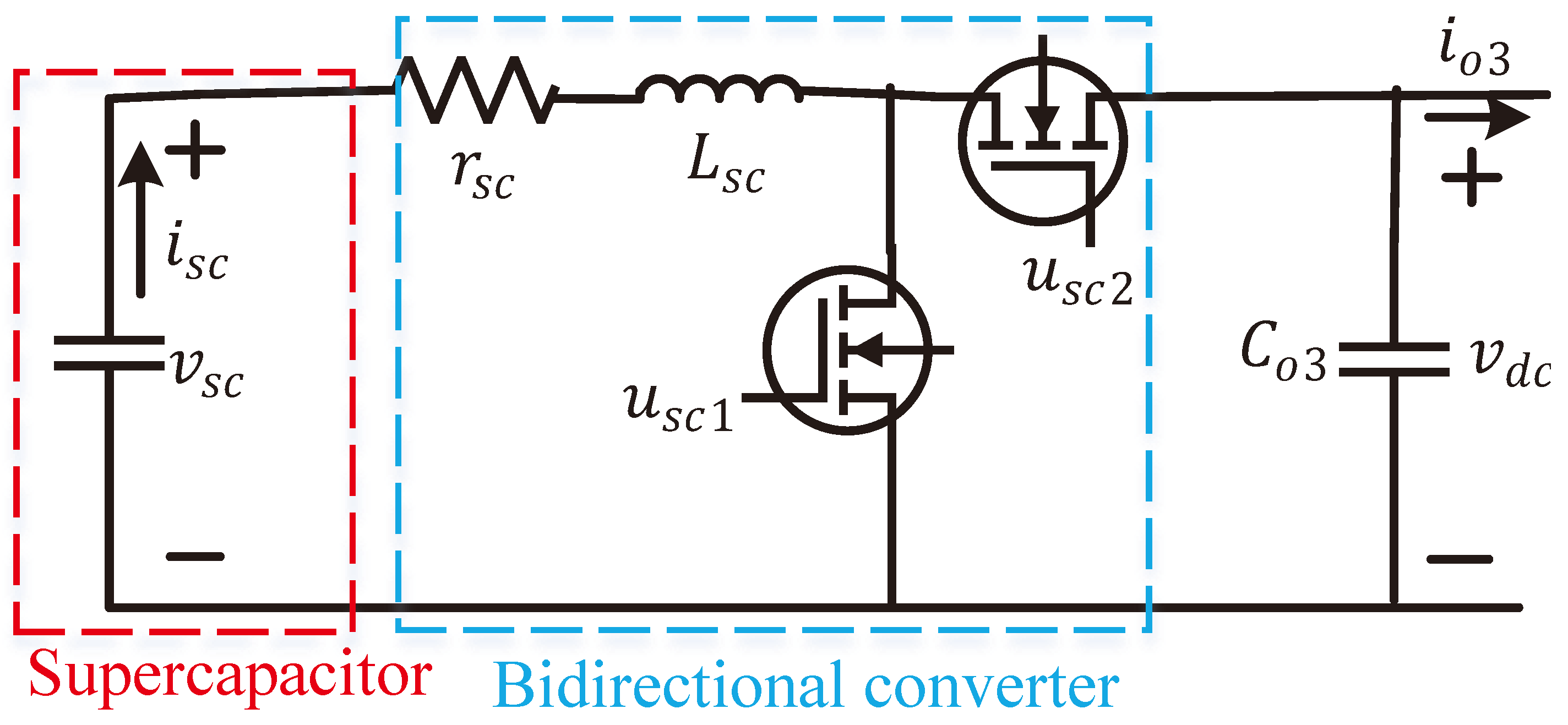
In this work, the concept of DESSs is used by employing a supercapacitor storage system in conjunction with a BESS with an aim of effectively enhancing the transient voltage stability of the common DC-bus voltage in a DC microgrid. At the same time, the supercapacitor storage system maintains the power balance of the islanded DC microgrid in very quicker way even after being affected by severe transient events as it has very high power density. Therefore, supercapacitor storage system compensates the sluggish performance of BESSs during fast changes in the output power or solar PV systems as well as the load demand. Furthermore, it significantly reduces the charging and discharging stresses on the BESS and, hence, improves the lifetime of the BESS. The electrical equivalent circuit of the supercapacitor storage system along with a bidirectional DC–DC converter is shown in Figure 4, and its dynamics can be represented using the set of following equations [33]:
d i s c d t = v s c r s c i s c v d c ( 1 u s c ) L s c
d v d c d t = i s c ( 1 u s c ) C 03 i 03 C 03
where v s c is the voltage of SCs, i s c is the output current of SCs, i 03 is the bidirectional converter’s output current, v d c is the DC-bus voltage, u s c is the control signal for a bidirectional converter of SCs, L s c is the inductor of a bidirectional converter, r s c is the DC–DC buck boost converter inductor’s internal resistance, and C 03 is the converter’s output capacitance.
The SoC along with the charging and discharging current limits of the supercapacitor storage system should be limited in a similar manner to that of the BESS which can be expressed as:
S o C S C , m i n S o C S C ( t ) S o C S C , m a x
i s c , m i n i s c ( t ) i s c , m a x
It is worth noting that there are no requirements for maintaining the minimum SoC for the SC. However, the limits are placed here to avoid over or under charging as well as to provide more opportunity for charging the BESS.

3. Proposed EMS-Based Control Strategy

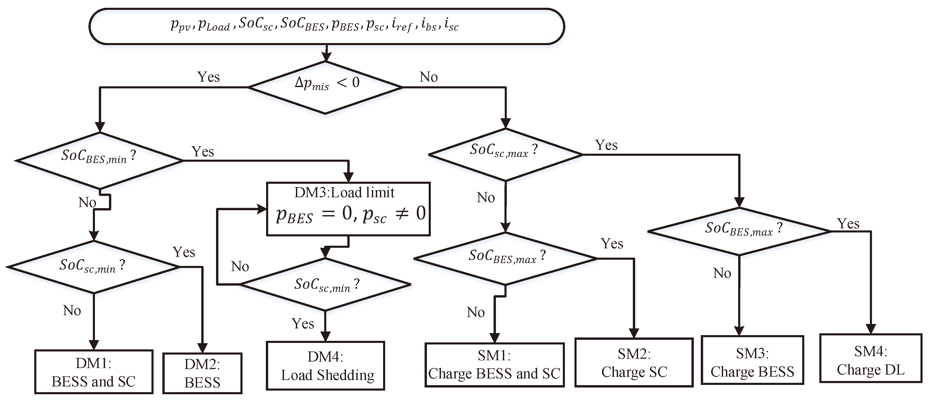
The proposed EMS-based control strategy is used to maintain the power balance while ensuring the voltage stability of DC microgrids by keeping the DC-bus voltage within the limit of its desired value. Figure 5 shows the flow chart of the proposed EMS-based control strategy. The power balance within the DC microgrid indicates that the power from the PV generation matches with the load demand, i.e., there is no mismatch between the generation and demand. Since the DC microgrid in this paper uses a solar PV system to generate power, there are huge fluctuations in the output power and the load varies continuously. Hence, there is power mismatch in the DC microgrid and the common DC-bus voltage experiences frequent fluctuations. The fluctuations in the DC-bus voltage sometime violate the voltage limit for the voltage stability. In such a condition, the DESS is used to minimize this power mismatch and maintain the voltage stability. The proposed EMS-based control scheme uses the reference currents i b s , r e f and i s c , r e f for the BESS and SC, respectively, to compensate the surplus and deficit power in a islanded DC microgrid. Now, the analytical expression for the power mismatch in a DC microgrid can be described through the following equation [5]:
Δ p m i s = v d c i d c = C d c v d c d v d c d t = p p v ± p B a t ± p s c p L o a d
where Δ p m i s is the mismatch or net power of DC microgrids, i d c = C d c d v d c d t is the output DC current, p p v is the output power of a PV system at maximum power point, p B a t is the output power of the BESS, p s c is the output power of the SC, p L o a d is the load demand, C d c is the equivalent capacitance of the DC- bus, and d v d c d t is the rise or drop voltage of a DC-bus.
From Equation (13), it can be seen that the common DC-bus voltage needs to be regulated to its desired value in order to ensure the power balance. A proportional integral (PI) controller can be used to regulate this common DC-bus voltage by controlling current of the DESS and the desired voltage can be obtained by minimizing the difference between the reference voltage v d c , r e f and measured voltage v d c , m e a s for which Equation (13) can be rewritten as follows:
p p v ( t ) ± p B a t ( t ) ± p s c ( t ) p L o a d ( t ) = K p ( v d c , r e f v d c , m e a s ) + K i ( v d c , r e f v d c , m e a s )
where K p and K i are proportional and integral gains of the PI controller, respectively. From Equation (14), it can be observed that the power balance can be obtained if the fluctuations in the common DC-bus voltage become zero. It is worth noting the slight variations in the common DC-bus voltage can be accepted. During the practical operations of DC microgrids, there are two operational modes as surplus power and deficit power modes. The proposed EMS-based control strategy ensures the power balance in both modes by appropriately charging or discharging the DESS while maintaining the SoC within the feasible limit. Based on these two operational modes, a comprehensive analysis of the proposed EMS-based control strategy is provided in the following subsections by considering different possible scenarios for each operating mode.

3.1. Deficit Power Mode

This mode appears when the output power of the PV unit is not sufficient to meet the total load demand (i.e., Δ P m i s < 0 ). In this condition, the proposed EMS-based control scheme regulates the switching control actions of the DESS in such a way that the DESS discharges to make up the deficit power of the islanded DC microgrid. Depending on the constraints related to the SoC and current of the DESS, different possible scenarios could be demonstrated to analyze the stable operation of islanded DC microgrids, as indicated in Figure 5. All these scenarios are explained in the following.
Scenario 1 or DM1 (discharging both SC and BESS): The reference current for controlling of the charge current of the DESS is calculated from the difference between the output power of the PV unit and load demand. In this scenario, the required current is kept at the maximum discharge current limit of the BESS and SC while the SoC of both BESS and SC is kept at a higher value than the minimum SoC. Therefore, the power mismatch within the DC microgrid is managed through both battery and SC. In this scenario, the SC is discharged first to inject the power into the microgrid for quickly tackling transients due to variations in the output power of the solar PV unit and load demand so that the voltage stability is ensured. In this scenario, the SC is fully discharged before the battery.
Scenario 2 or DM2 (discharging only the battery): This scenario is an extension of DM1 in which it is considered that the SC is fully discharged while the power is still sufficiently available to compensate the power shortage of the DC microgrid. In this situation, the battery is within its SoC limit.
Scenario 3 or DM3 (fully discharging the battery, partially discharging the SC, and partially shedding load): In this mode, it is considered that the battery is fully discharged, i.e., the SoC of the battery reaches to its minimum value. Furthermore, it is considered that the SC can release some energy but it is not sufficient to match the load demand. Hence, the load shedding action is enforced.
Scenario 4 or DM4 (no power from the DESS): In this scenario, it is assumed that the DESS is fully discharged, i.e., no power from both SC and battery. However, the solar PV unit supplies power to partially meet the load demand for which it is essential to shed the load.

3.2. Surplus Power Mode

Due to uncertainties in the output power of the PV units and variations in the load demand during the operation of the DC microgrid, there are some instances where the power generation from the solar PV system is higher than the total load demand, i.e., there is an excess power and this can be categorized as surplus power mode. During this mode, the load demand is met by the PV system and the remaining power of the PV system is stored into DESS through the bidirectional converter. The excess energy within the microgrid can be controlled using a current control strategy embedded with an EMS which can be described through following four possible scenarios.
Scenario 5 or SM1 (charging both BESS and SC): In this scenario, the power mismatch within the microgrid is first calculated and the SoC for the DESS (i.e., both BESS and SC) is observed. It is also assumed that the SoCs for both BESS and SC are less their maximum limits, i.e., less than S o C B E S , m a x and S o C S C , m a x . The DESS is charged with the surplus energy and the inclusion of the SC flattens transient behaviors with changes in DC microgrids due to its faster dynamic capability to adapt changes.
Scenario 6 or SM2 (full charging of the BESS and partial charging of the SC): In this mode, the SoC for the BESS gradually increases and fully recharged while the SC still has the ability to charge from the solar PV unit under MPPT constraints.
Scenario 7 or SM3 (both BESS and SC are fully charged): This scenario is considered by considering the situation when both BESS and SC are fully charged. It is worth noting that the excess power from the solar PV unit exactly matches with the available capacity of the DESS and load demand during this mode.
Scenario 8 or SM4 (full charging of the DESS and extra power from the PV unit): In this operating mode, it is considered that the DESS is fully charged and there is still excess power from the solar PV unit which is consumed by the dump load (DL). Based on all these scenarios, the performance of the proposed EMS-based control strategy is analyzed in the following section.

4. Simulation Results

The proposed EMS-based control scheme was employed on the DC microgrid shown in Figure 1. In this figure, it can be seen that the load is directly connected to the common DC-bus and the rated load voltage, i.e., the common DC-bus voltage is considered as 120 V. Hence, the desired voltage level for the DC–DC converter with the solar PV unit is 120 V, which is the same as for the bidirectional converters during the discharging modes for both BESS and SC. In this study, it was assumed that the load within the DC microgrid can be varied from 0 to 10 kW and the output power from the solar PV unit was considered as 10 kW at the MPP under standard atmospheric conditions. The output voltage of the PV array was considered as 90 V and DC–DC boost converter was used to make the voltage as 120 V where this converter was controlled by the proposed EMS-based control scheme. In this study, the rated voltage and capacity of the BESS were considered as 72 V and 200 Ah, respectively. Here, a lithium-ion battery was used as the BESS. Similarly, SC having the rated voltage as 67.2 V and capacity as 10.4 Ah was used to have the DESS. This means that the proposed EMS-based scheme ensures the desired voltage as 72 V for the BESS and 67.2 V for the SC during the charging mode. The gain parameters used for different controllers are provided in Appendix A Table A1. This newly designed energy management system was used to generate the reference signals for the controllers used in different components. Usually, the control actions require eliminating the transient characteristics within few seconds (definitely depending on the requirement). This energy management system can be integrated with the existing SCADA system and it would not require any special hardware or data acquisition system.
The effectiveness of utilizing the DESS in conjunction with the proposed EMS-based control scheme was evaluated in terms of maintaining the stability of the common DC-bus voltage and power balance under any operating condition (i.e., in both transient and steady-state conditions) of the microgrid. The results obtained using the proposed EMS-based control scheme for the DC microgrid with the DESS were compared with the same having only the BESS, i.e., without the SC. Different scenarios were considered during the simulation and the simulation was carried out using the SIMPOWER Tool Box in MATLAB/Simulink platform. It is worth mentioning that the time step for the simulation was considered as 5 μ s.
At the beginning of the simulation, the solar PV unit operated at the MPP under standard atmospheric conditions. It is worth noting that the standard atmospheric conditions were considered as a situation when the cell temperature is 25 C and the solar irradiation is 1000 W/m 2 . In this condition, the solar PV unit generates 10 kW and the load demand is considered as 4 kW. The initial values of the SoC for the BESS and SC were considered as 60% and 77.7%, respectively. This means that both BESS and SC were charged from the previous operational cycle.
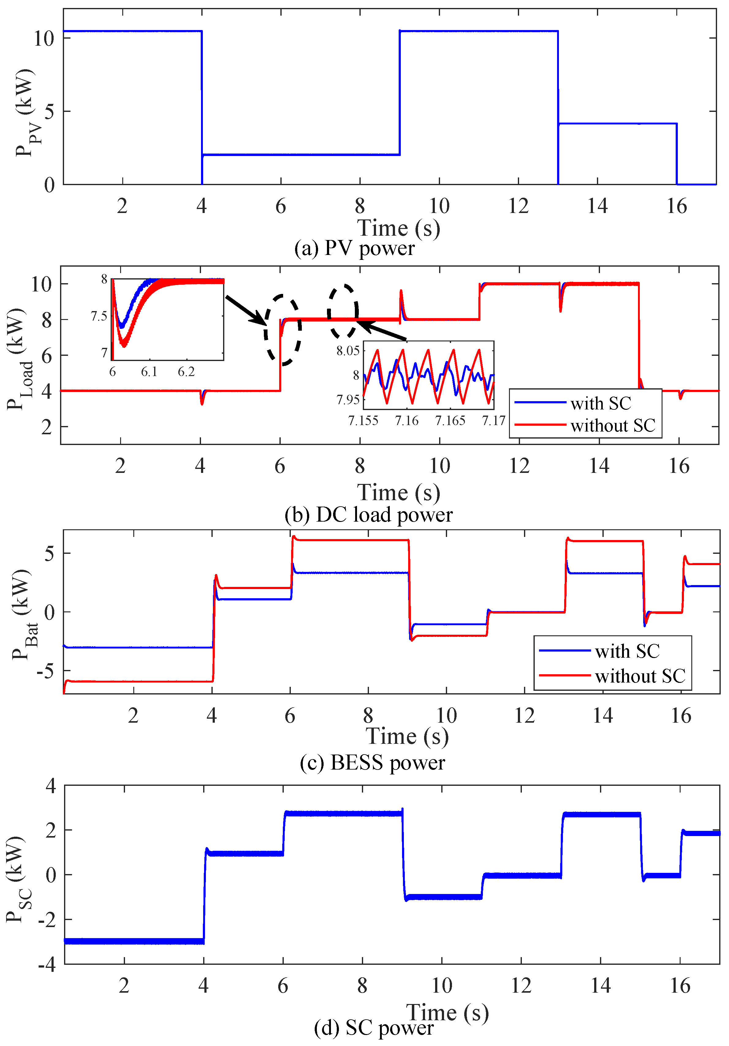
During the first interval of the operation, i.e., 0 ≤ t < 4 s, the power generated from the solar PV unit (10 kW) is higher than the load demand (4 kW). Since the values of the SoC for both BESS and SC are lower than their maximum limits, the excess power (i.e., 6 kW) available within the microgrid is stored into the DESS. At this instant, the proposed EMS-based control strategy regulates the bidirectional DC–DC converters of the BESS and SC to ensure the appropriate charging for maintaining the power balance within the DC microgrid. At the same time, it ensures the fluctuations in the common DC-bus voltage. At this instant, the power balance within the DC microgrid can be clearly seen from power responses of different components, as shown in Figure 6, and an insight about the voltage stability of the DC microgrid can be found from the common DC-bus voltage, as shown in Figure 7. The charging of the DESS can be evidenced from the increases in the SoCs for both BESS and SC, as depicted in Figure 8. This operational scenario actually represent SM1.
During the second interval, i.e., 4 ≤ t < 9 s, it is considered that the output power of the PV unit suddenly drops from 10 to 2 kW due to the changes in the solar irradiation while the total load demand is still 4 kW until t = 6 s, which is increased to 8 kW at t = 6 s, and the operation of the DC microgrid continues until t = 9 s. Hence, the load demand is higher than the generation from the solar PV unit throughout this interval. Here, the proposed EMS-based control scheme allows releasing the energy equivalent to 2 kW from the DESS through discharging during the interval from t = 4 s to t = 6 s along with additional 4 kW from t = 6 s to t = 9 s. During this interval, both BESS and SC equally discharge to ensure the power balance, which can be evidenced from the power responses, as provided in Figure 6. The control actions for both BESS and SC are also regulated to achieve the desired load voltage or common DC-bus voltage, i.e., 120 V. The changes in the output power of the solar PV unit at t = 4 s and the load demand at t = 6 s affect the common DC-bus voltage response, as shown in Figure 7, in it can be seen that there are fewer disturbances with the DESS as compared to the response with only the BESS. Since the DESS discharges during this operating scenario, the SoCs for both BESS and SC will decrease, which can also be seen in Figure 8. This operating interval represents the operating mode DM1.
At t = 9 s, the output power of the solar PV unit suddenly increases from the 2 to 10 kW and continues this power generation until t = 13 s while the load demand is kept as 8 kW until t = 11 s. During this condition (i.e., t = 9 s to t = 11 s), the DC microgrid operates with Scenario 5, i.e., SM1 where both BESS and SC are equally charged to store energy equivalent to 2 kW. These can easily be seen from all responses in Figure 6a–d. At t = 11 s, the load demand suddenly changes from 8 to 10 kW, which is kept until t = 15 s. Since the output power of the PV unit is 10 kW until t = 13 s., there is no power mismatch from t = 11 s to t = 13 s and the DESS is not charged, as shown in Figure 6c,d. This means that the EMS-based control scheme does not regulate the bidirectional DC–DC converters for both BESS and SC from t = 11 s to t = 13 s. Hence, the SoCs for both BESS and SC are maintained as constant from t = 11 s to t = 13 s, as shown in Figure 8 while the common DC-bus voltage is slightly disturbed, as shown in Figure 7, due to all these changes. However, the proposed scheme maintains the post-disturbance voltage at 120 V. The power generation from the solar PV again drops to 4 kW at t = 13 s, which continues until t = 16 s. Since the load demand is 10 kW until t = 15 s, the DESS releases energy equivalent to 6 kW from t = 13 s to t = 15 s as the load demand reduces to 4 kW at t = 15 s, which continues until the end of this simulation window at t = 17 s. There is power balance in the DC microgrid from t = 15 s to t = 16 s as the generation from the solar PV unit matches with the load demand and, thus, the DESS does not charge and discharge, which is shown in Figure 8. However, the DESS is discharged for the remaining operation (i.e., from t = 16 s) as the output power from the PV unit reduces to zero at this instant and the only way to meet the load demand is to discharge the BESS. All these situations are depicted in Figure 6, Figure 7 and Figure 8.
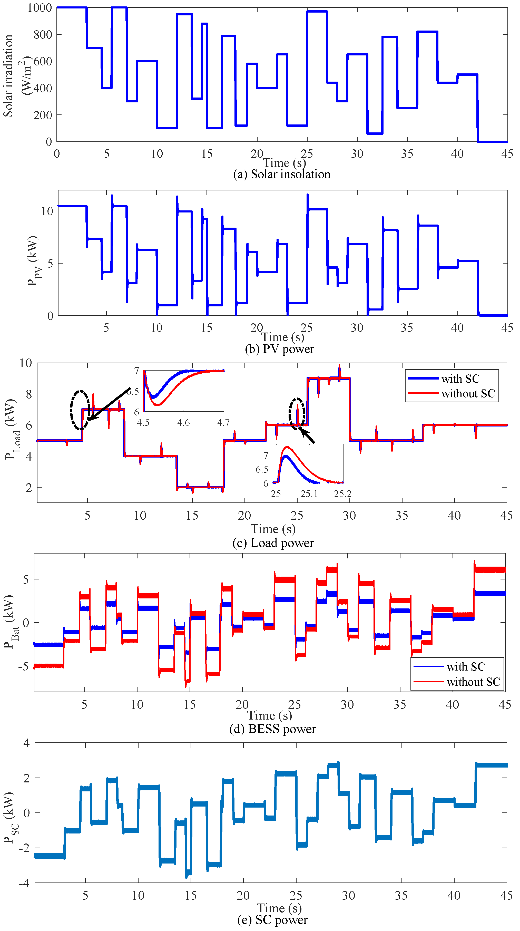
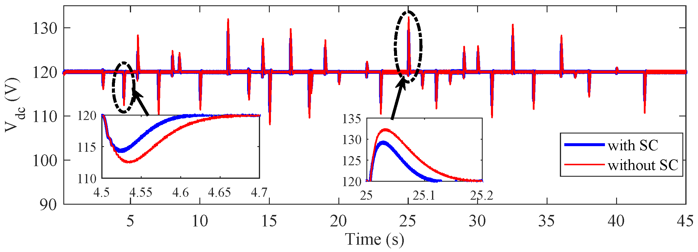
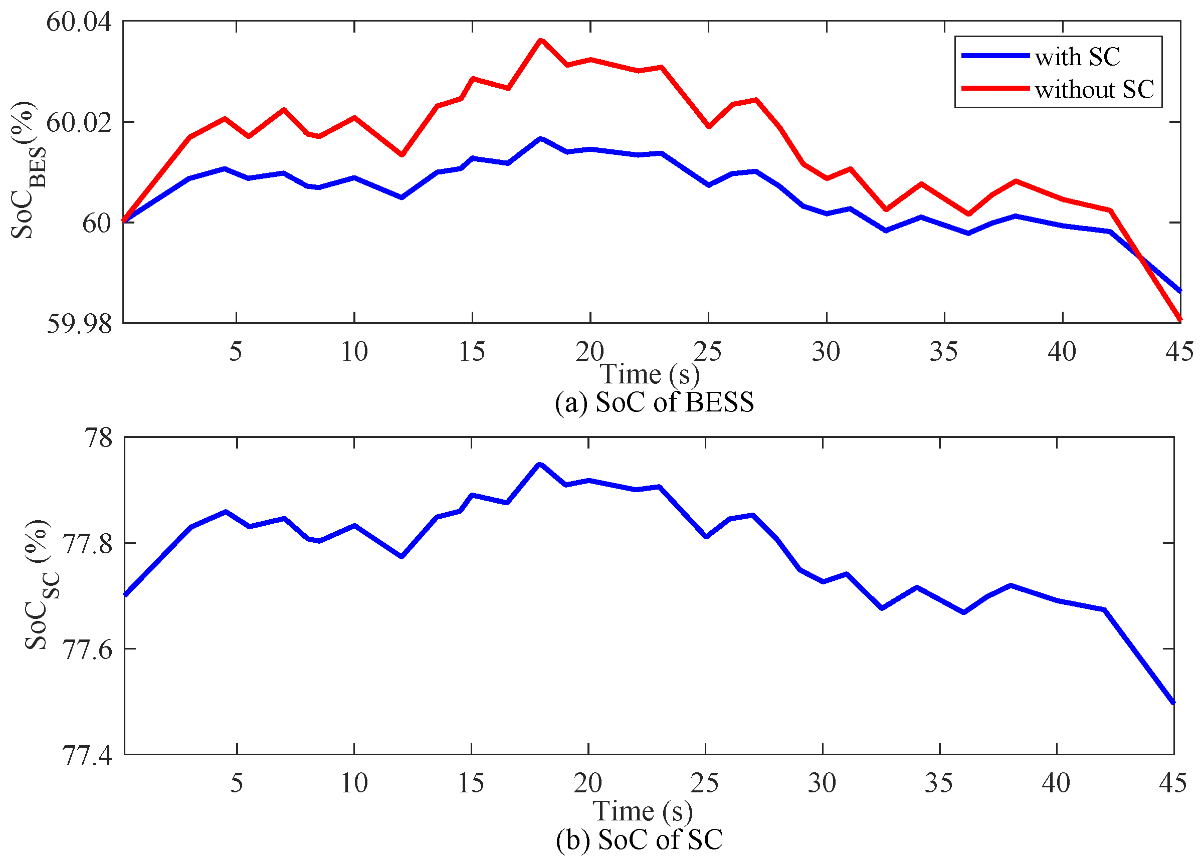
In Figure 6b and Figure 7, it can be clear observed that the DESS can quickly cope with changes in the load demand and power generation from the solar PV unit while comparing with the responses for the DC microgrid having only the BESS. In Figure 8, it can be seen that the variations in the SoC for the BESS is much lower when the SC is used. This means that the operation of a DC microgrid having a DESS helps to avoid the deep charging or discharging of the BESS and, thus, the lifetime of the BESS is improved. In Figure 6a, it can be seen that the output power of the PV unit becomes zero at some instances (particularly, for the values closer to zero). This is mainly because of the transient issues and values being closer to zero. Furthermore, Figure 6, Figure 7 and Figure 8 show that there are step changes in the solar irradiation for which it is quite hard to distinguish the response time between the BESS and DESS. However, this would not be the case during practical operating conditions as the solar irradiation randomly varies even worse than shown in Figure 9a. The response time is affected if these variations in the solar irradiation are more frequent, as in Figure 9c. The power profiles of different components within the DC microgrid are shown in Figure 9b–e, in which it is clear that there exist more transients. In this condition, the common DC-bus voltage and relevant SoCs are shown in Figure 10 and Figure 11.
From all these simulation results, it can be seen that the DESS with the proposed EMS-based control scheme enhances the operational reliability in terms of maintaining both voltage stability and power balances under different operating scenarios.
5. Conclusions

The merit of having an EMS-based control scheme in a DC microgrid with the DESS was investigated through rigorous simulation studies. The simulation results clearly depict that the EMS-based control strategy for a DC microgrid with the DESS tackles the transient events in a much better way compared to that of having system with only the BESS. The results also reveal that the newly developed EMS-based control strategy improves the overall dynamic performance of DC microgrids in terms of maintaining the power balance and voltage stability under severe transients due to variations in the output power of solar PV units and changes in the load demand. Furthermore, this EMS-based control strategy ensures the extended lifetime of the BESS by keeping the variation in the SoC lower than that of a DC microgrid operating without a SC.
The main focus of the energy management system in this manuscript is only on maintaining the dynamic performance rather than the calculation of other features such as the improvements in the lifetime of the BESS. In future works, the improvements in the lifetime of the BESS can be calculated by using the load, generation, charging profiles, discharging profiles, etc. while considering the longer simulation period (e.g., yearly). Furthermore, the proposed scheme can be extended by employing a nonlinear adaptive control scheme in order to replace the PI controller presented in this work, as this would provide robustness against variations parameters and external disturbances.

Author Contributions

Conceptualization, S.K.G., T.K.R., and M.A.M.; methodology, S.K.G. and T.K.R.; software, S.K.G. and M.A.H.P.; validation, S.K.G. and T.K.R.; formal analysis, S.K.G., T.K.R., and M.A.H.P.; investigation, S.K.G. and T.K.R.; writing—original draft preparation, S.K.G. and T.K.R.; writing—review and editing, T.K.R., A.K.S., and M.A.M.; supervision, T.K.R., A.K.S., and M.A.M.; and project administration, T.K.R. and M.A.M. All authors have read and agreed to the current version of the manuscript.

Funding

This research received no external funding.

Conflicts of Interest

The authors declare no conflict of interest.

Abbreviations

BESSBattery Energy Storage System
BTSBase Transceiver System
DESSDual Energy Storage System
DMDeficit Power Mode
EMSEnergy Management System
ESSEnergy Storage System
HESSHybrid Energy Storage System
ICIncremental Conductance
MPPTMaximum Power Point Tracking
PVPhotovoltaic
SCSupercapacitor
SoCState of Charge
SMSurplus Power Mode

Appendix A

The gain values of decentralized-based classic PI controllers for different components of DC microgrids are provided in Table A1. In addition, the data sheet of various components of DC microgrids is provided in Table A2.
Table A1. Gain parameters of classic PI controllers.
PI Controllers K p K i
PV210
BESSs10120
SCs570
Table A2. System Parameters of Proposed DC microgrids.
PV System ParametersValues
Maximum Voltage of PV System90 V
Maximum Current of PV System112 A
Rated Output Power at MPP10 kW
Open Circuit voltage of PV System112.8 V
Short Circuit Current of PV System119.7 A
BESSs Model Parameters
Nominal Voltage of BESSs72 V
Rated Capacity200 Ah
Maximum Capacity200 Ah
Capacity (Ah) @ Nominal Voltage180.86 Ah
Nominal discharge current86.95 A
Fully charged voltage83.80 V
Cut-off Voltage54 V
Discharging and Charging Current Limit±80 A
Maximum SoC of BESSs90%
Minimum SoC of BESSs30%
Initial SoC of BESSs60%
SCs Model Parameters
Capacitance Value of Each Cell3000 F
Voltage of Each Cell2.7 V
Rated Voltage of SCs Stack67.2 V
Series Connected Cells Per Module25
Module Total Capacitance120 F
Energy of SCs Stack7 kWh
No. of Modules Connected in Parallel93
Rated Capacity of SCs Stack10.4 Ah
Discharging and Charging Current Limit±50 A
Maximum SoC of SCs90%
Minimum SoC of SCs30%
Initial SoC of SCs Stack77.70%

References

  1. Islam, S.N.; Mahmud, M.A.; Saha, S.; Haque, M.E. Linear precoder design for base station energy cooperation in DC microgrids. IET Renew. Power Gener. 2019, 13, 1076–1086. [Google Scholar] [CrossRef]
  2. Hossain, M.J.; Mahmud, M.A.; Milano, F.; Bacha, S.; Hably, A. Design of robust distributed control for interconnected microgrids. IEEE Trans. Smart Grid 2015, 7, 2724–2735. [Google Scholar] [CrossRef]
  3. Mahmud, M.; Hossain, M.; Pota, H.; Oo, A. Robust nonlinear distributed controller design for active and reactive power sharing in islanded microgrids. IEEE Trans. Energy Convers. 2014, 29, 893–903. [Google Scholar] [CrossRef]
  4. Sahoo, S.; Mishra, S.; Jha, S.; Singh, B. A Cooperative Adaptive Droop Based Energy Management and Optimal Voltage Regulation Scheme for DC Microgrids. IEEE Trans. Ind. Electron. 2019, 67, 2894–2904. [Google Scholar] [CrossRef]
  5. Mahmud, M.A.; Roy, T.K.; Saha, S.; Haque, M.E.; Pota, H.R. Robust nonlinear adaptive feedback linearizing decentralized controller design for islanded DC microgrids. IEEE Trans. Ind. Appl. 2019, 55, 5343–5352. [Google Scholar] [CrossRef]
  6. Azizi, A.; Peyghami, S.; Mokhtari, H.; Blaabjerg, F. Autonomous and decentralized load sharing and energy management approach for DC microgrids. Electr. Power Syst. Res. 2019, 177, 106009. [Google Scholar] [CrossRef]
  7. Roy, T.K.; Mahmud, M.A. Dynamic stability analysis of hybrid islanded DC microgrids using a nonlinear backstepping approach. IEEE Syst. J. 2017, 12, 3120–3130. [Google Scholar] [CrossRef]
  8. Yang, F.; Feng, X.; Li, Z. Advanced microgrid energy management system for future sustainable and resilient power grid. IEEE Trans. Ind. Appl. 2019, 55, 7251–7260. [Google Scholar] [CrossRef]
  9. Saha, S.; Roy, T.; Mahmud, M.; Haque, M.; Islam, S. Sensor fault and cyber attack resilient operation of DC microgrids. Int. J. Electr. Power Energy Syst. 2018, 99, 540–554. [Google Scholar] [CrossRef]
  10. Han, J.; Charpentier, J.F.; Tang, T. An energy management system of a fuel cell/battery hybrid boat. Energies 2014, 7, 2799–2820. [Google Scholar] [CrossRef] [Green Version]
  11. Whaite, S.; Grainger, B.; Kwasinski, A. Power quality in DC power distribution systems and microgrids. Energies 2015, 8, 4378–4399. [Google Scholar] [CrossRef] [Green Version]
  12. Han, Y.; Chen, W.; Li, Q. Energy management strategy based on multiple operating states for a photovoltaic/fuel cell/energy storage DC microgrid. Energies 2017, 10, 136. [Google Scholar] [CrossRef] [Green Version]
  13. Logenthiran, T.; Srinivasan, D.; Khambadkone, A.M.; Aung, H.N. Multiagent system for real-time operation of a microgrid in real-time digital simulator. IEEE Trans. Smart Grid 2012, 3, 925–933. [Google Scholar] [CrossRef]
  14. Ambia, M.N.; Al-Durra, A.; Muyeen, S. Centralized power control strategy for AC-DC hybrid micro-grid system using multi-converter scheme. In Proceedings of the IEEE IECON 2011—37th Annual Conference of the IEEE Industrial Electronics Society, Melbourne, Australia, 7–10 November 2011; pp. 843–848. [Google Scholar]
  15. Radwan, A.A.A.; Mohamed, Y.A.R.I. Networked control and power management of AC/DC hybrid microgrids. IEEE Syst. J. 2014, 11, 1662–1673. [Google Scholar] [CrossRef]
  16. Kardan, M.A.; Asemani, M.H.; Khayatian, A.; Vafamand, N.; Khooban, M.H.; Dragičević, T.; Blaabjerg, F. Improved stabilization of nonlinear DC microgrids: Cubature Kalman filter approach. IEEE Trans. Ind. Appl. 2018, 54, 5104–5112. [Google Scholar] [CrossRef] [Green Version]
  17. Guo, F.; Xu, Q.; Wen, C.; Wang, L.; Wang, P. Distributed secondary control for power allocation and voltage restoration in islanded DC microgrids. IEEE Trans. Sustain. Energy 2018, 9, 1857–1869. [Google Scholar] [CrossRef]
  18. Moayedi, S.; Davoudi, A. Distributed tertiary control of DC microgrid clusters. IEEE Trans. Power Electron. 2015, 31, 1717–1733. [Google Scholar] [CrossRef]
  19. Golshannavaz, S.; Mortezapour, V. A generalized droop control approach for islanded DC microgrids hosting parallel-connected DERs. Sustain. Cities Soc. 2018, 36, 237–245. [Google Scholar] [CrossRef]
  20. Sadabadi, M.S.; Shafiee, Q. Scalable Robust Voltage Control of DC Microgrids with Uncertain Constant Power Loads. IEEE Trans. Power Syst. 2019, 35, 508–515. [Google Scholar] [CrossRef]
  21. Yang, X.; Li, X.; He, H.; Zhang, Y.; Xu, Z. Dynamic Power Sharing and Autonomous Voltage Regulation in Islanded DC Microgrids. In Proceedings of the IEEE Power & Energy Society Innovative Smart Grid Technologies Conference (ISGT), Washington, DC, USA, 17–20 February 2019; pp. 1–5. [Google Scholar]
  22. Chen, X.; Shi, M.; Zhou, J.; Chen, Y.; Zuo, W.; Wen, J.; He, H. Distributed cooperative control of multiple hybrid energy storage systems in a DC microgrid using consensus protocol. IEEE Trans. Ind. Electron. 2019, 67, 1968–1979. [Google Scholar] [CrossRef]
  23. Roy, T.K.; Mahmud, M.A.; Oo, A.M.T.; Haque, M.E.; Muttaqi, K.M.; Mendis, N. Nonlinear adaptive backstepping controller design for islanded DC microgrids. IEEE Trans. Ind. Appl. 2018, 54, 2857–2873. [Google Scholar] [CrossRef]
  24. Mahmud, M.A.; Roy, T.K.; Islam, S.N.; Saha, S.; Haque, M.E. Nonlinear decentralized feedback linearizing controller design for islanded DC microgrids. Electr. Power Compon. Syst. 2017, 45, 1747–1761. [Google Scholar] [CrossRef]
  25. Akter, M.N.; Mahmud, M.A.; Oo, A.M.T. A hierarchical transactive energy management system for energy sharing in residential microgrids. Energies 2017, 10, 2098. [Google Scholar] [CrossRef] [Green Version]
  26. Hwang, C.S.; Kim, E.S.; Kim, Y.S. A decentralized control method for distributed generations in an islanded dc microgrid considering voltage drop compensation and durable state of charge. Energies 2016, 9, 1070. [Google Scholar] [CrossRef] [Green Version]
  27. Yin, C.; Wu, H.; Locment, F.; Sechilariu, M. Energy management of DC microgrid based on photovoltaic combined with diesel generator and supercapacitor. Energy Convers. Manag. 2017, 132, 14–27. [Google Scholar] [CrossRef]
  28. Tankari, M.A.; Camara, M.B.; Dakyo, B.; Lefebvre, G. Use of ultracapacitors and batteries for efficient energy management in wind–diesel hybrid system. IEEE Trans. Sustain. Energy 2012, 4, 414–424. [Google Scholar] [CrossRef]
  29. A Kamel, A.; Rezk, H.; Shehata, N.; Thomas, J. Energy management of a DC microgrid composed of photovoltaic/fuel cell/battery/supercapacitor systems. Batteries 2019, 5, 63. [Google Scholar] [CrossRef] [Green Version]
  30. Tani, A.; Camara, M.B.; Dakyo, B. Energy management in the decentralized generation systems based on renewable energy—Ultracapacitors and battery to compensate the wind/load power fluctuations. IEEE Trans. Ind. Appl. 2014, 51, 1817–1827. [Google Scholar] [CrossRef]
  31. Sanjeev, P.; Padhy, N.P.; Agarwal, P. Peak energy management using renewable integrated DC microgrid. IEEE Trans. Smart Grid 2017, 9, 4906–4917. [Google Scholar] [CrossRef]
  32. Javed, K.; Ashfaq, H.; Singh, R.; Hussain, S.; Ustun, T.S. Design and performance analysis of a stand-alone PV system with hybrid energy storage for rural India. Electronics 2019, 8, 952. [Google Scholar] [CrossRef] [Green Version]
  33. Tummuru, N.R.; Mishra, M.K.; Srinivas, S. Dynamic energy management of hybrid energy storage system with high-gain PV converter. IEEE Trans. Energy Convers. 2014, 30, 150–160. [Google Scholar] [CrossRef]
Figure 1. Configuration of the proposed Islanded DC microgrid.
Energies 13 02992 g001
Figure 2. A solar PV system with a DC–DC boost converter.
Energies 13 02992 g002
Figure 3. Electrical equivalent circuit representation of a BESS coupled to a bidirectional DC–DC converter.
Energies 13 02992 g003
Figure 4. Equivalent circuit representation of a supercapacitor coupled to a bidirectional DC–DC converter.
Energies 13 02992 g004
Figure 5. Flow chart of the proposed EMS-based control strategy.
Energies 13 02992 g005
Figure 6. Power responses of different components within the DC microgrid under different operating conditions considering step changes in the solar irradiation.
Energies 13 02992 g006
Figure 7. Common DC-bus voltage under varying output power from the PV unit and changing load conditions with step changes in the solar irradiation.
Energies 13 02992 g007
Figure 8. State of charge (SoC) responses for both BESS and SC under surplus and deficit power modes with step changes in the solar irradiation.
Energies 13 02992 g008
Figure 9. Power responses of different components within the DC microgrid under different operating conditions considering more fluctuations in the solar irradiation.
Energies 13 02992 g009
Figure 10. Common DC-bus voltage under varying output power from the PV unit and changing load conditions considering more fluctuations in the solar irradiation.
Energies 13 02992 g010
Figure 11. State of charge (SoC) responses for both BESS and SC under surplus and deficit power modes considering more fluctuations in the solar irradiation.
Energies 13 02992 g011