Article

Design and Construction of a New Metering Hot Box for the In Situ Hygrothermal Measurement in Dynamic Conditions of Historic Masonries

1
Istituto Nazionale di Fisica Nucleare, Sezione di Ferrara, 44122 Ferrara, Italy
2
Department of Engineering and Architecture of the University of Parma, 43124 Parma, Italy
3
Architettura>Energia Research Centre, Department of Architecture-University of Ferrara, 44121 Ferrara, Italy
4
Eurac Research, 39100 Bolzano, Italy
*
Author to whom correspondence should be addressed.
Energies 2020, 13(11), 2950; https://doi.org/10.3390/en13112950
Submission received: 29 May 2020 / Revised: 5 June 2020 / Accepted: 6 June 2020 / Published: 9 June 2020

Abstract

:
The main purpose of the HeLLo project is to contribute to data available on the literature on the real hygrothermal behavior of historic walls and the suitability of insulation technologies. Furthermore, it also aims at minimizing the energy simulation errors at the design phase and at improving their conservation features. In this framework, one of the preliminary activities of the study is the creation of a real in situ hot box to measure and analyze different insulation technologies applied to a real historic wall, to quantify the hygrothermal performance of a masonry building. Inside this box, ‘traditional’ experiments can be carried out: recording heat flux, surface temperature, and air temperatures, as well as relative humidity values through the use of a new sensing system (composed of thermocouples and temperature/relative humidity combined sensors). Within this paper, the process of development, construction, and validation of this new metering box is exhibited. The new hot box, specifically studied for historic case studies, when compared to other boxes, presents other advantages compared to previous examples, widely exemplified.

Graphical Abstract

1. Introduction

Energy refurbishment of existing buildings is one of the priorities of the European policies to reduce fuel consumption, starting from the recognition of the ‘exemplary role of public bodies’ buildings (art.5 2012/27/UE) [1] to activate effective strategies in the private building stock. Existing buildings in the European Union are, indeed, responsible for 40% of final energy consumption [2] and for 36% of carbon dioxide (CO2) emissions [3]. Approximately 35% of the buildings are more than 50 years old [3]. Considering the low rate of new buildings construction, 3% in Europe [4], and 2% in the USA [5], energy efficiency in existing, historical, and historic buildings is one of the greatest opportunities towards a sustainable future.
Besides the social and cultural value of all historic buildings, the specific value of heritage assets in Italy strongly justifies the origin of the current research: according to the Italian Ministry for Cultural Heritage and Activities, there are more than 20,000 historic centers of different ages. In light of such numbers, it is evident that many Italian cities are largely made up of historic buildings, which almost often require a greater commitment in the design of conservative and improving interventions than those devoted to the process of new construction. Nonetheless, this is also verified in many other European heritage city centers. Two examples could be pointed out: Edinburgh (Scotland) and Antwerp (Belgium). In 1995, UNESCO added the Old and New Towns of Edinburgh as a World Heritage Site [6]. In this site, 75% of the 4500 individual buildings are listed for their special architectural or historic interest. This city’s latest management plan concerning the heritage site (2017–2022) has 6 main objectives and 39 actions, of which stands out” strengthening care and maintenance of buildings and streets’ and the ‘sustainable re-use of underused and unused buildings” [6]. In Antwerp, instead, there are several listed buildings, such as the Vleeshuis Museum located in the historic center. This significant building has been the object of study [7] in various domains (e.g., evaluation of brick masonry or the assessment of hygrothermal parameters and conservation of important housed collection).
The interest in historic and historical buildings has been gaining cultural and social strategic roles. One important way of preserving built heritage for the future is to keep it in use and to accommodate new uses, avoiding its transformation into a ‘museum’ and preserving its cultural memory. In order to make this operation successful, it is mandatory for their adaptation to today’s comfort requests for indoor human activities. Moreover, promoting the control of hygrothermal parameters and indoor air quality in such buildings also means assuring better conservation of the decorative features that make them distinguishable and enhance their architectural quality.
The building envelope plays an important role in terms of energy transmission. Particularly, the opaque surface in historic buildings constitutes the largest surface of the envelope, and heat losses through this element are, therefore, of most importance [8,9,10]. In fact, some authors defend that in historic buildings heat loss through windows is only 10%, while walls and roof account for 60% (35% and 25%, respectively) [11,12]. This means that the intervention aiming to enhance the energy performance of the building should involve the envelope’s components to reach a high level of efficiency. As well-known, sometimes, it is impossible due to the presence of architectural features to be preserved, and the project has to focus on different strategies. In other cases, the envelope’s insulation is possible operating only on the inner façade of the building. Unfortunately, also in these situations, other difficulties may occur, hindering the good result of the operation.
One of the most significant issues in the field of efficiency topics is the buildings energy consumption gap [13,14,15] between design and post-occupancy phase [16,17]. In many cases, it has been verified that this gap is due to occupants’ behavior [18,19], but it can also be justified by erroneous decisions or values accepted at the design phase (i.e., poor practice or uncertainty in building energy simulation—BES [20]). Many authors have been demonstrating the limitations of traditional BES tools and procedures for the estimation of energy performance of historical buildings [21,22,23,24,25]. This topic reaches a significant dimension in historic buildings refurbishment, once the real wall composition of such buildings is frequently unknown [26] and, for practical matters, in many occasions, several projects and estimations are based on general assumptions [27].
The calibration of the hygrothermal models with measured data is very important to avoid irreparable damage to historic buildings. The combination of several hygrothermal variables [e.g., heat flux (φ), surface temperature (Ts), air temperature (Ta), and relative humidity (RH)] should lead to more reliable models.

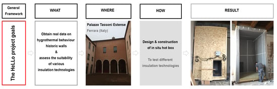
2. Aims and Methodology

The main purpose of this study was to contribute to data available on literature on the real hygrothermal behaviour of historic walls and the suitability of insulation technologies, also aiming at minimizing the energy simulation errors at the design phase and at improving their conservation features (i.e., avoiding risks of condensation or damaging their structure). These errors can become very significant. For example, the wrong definition of the thermal behaviour of a thick and heavy external wall, a very common situation in historic buildings (e.g., “the results divergence in thermal mass simulation using different tools” [28] (p. 74) or simply the use of different modelling tools [23]), might lead not only to the definition or to the choice of inappropriate insulation solutions (e.g., risking at generating condensation by changing the original hygrothermal wall behaviour), but also it can lead to mistaken thermal spatial requirements or to over dimensioning of HVAC (heating, ventilation and air conditioning) systems. The negative implication of miss-sized systems and the corresponding increased energy consumption has being recognized in the scientific community [29,30,31]. Furthermore, moisture reduces thermal performance and causes deterioration of insulation materials [7,8,9,25].
On the basis of these assumptions, the energy refurbishment of historic heritage with testimonial value is an asset. Given the impossibility to remove samples to be tested in the laboratory, and the likely unknown hygrothermal behaviour of historic walls, in situ measurement methods must be more frequently implemented, expeditious, simple to operate. Though each historic building presents unique features, the developed methods should be, preferably, replicable and repeatable.
In this framework, the HeLLo research project [32] created a real in situ laboratory of measurement to analyse different insulation technologies when applied on a real historic building to quantify the hygrothermal performance of a masonry building. As a first step of the research, the authors developed a version of a revised in situ metering hot box, topic of the present paper, perfectly thought for historic buildings, to adapt the standard in situ measurement techniques to the historic case study. The paper presents the main characteristics and uses of this hot box for in situ hygrothermal tests.

3. State of the Art

The literature shows two different kinds of in situ tests: (i) test for determining the thermal performance of building elements, in terms of thermal resistance (R-value or R), thermal conductance (C-value or C), or thermal transmittance (U-value or U) [33]; and (ii) hygrothermal monitoring for determining the hygrothermal behaviour of the various wall layers [7,34].
First, commonly used standard tests to experimentally determine the thermal performances of walls [35] were divided in two groups: (i) In situ tests measurements based on the use of the heat flow meter (HFM) method [36,37,38] or the quantitative infrared thermography testing (ITT) [39,40]; and (ii) laboratory tests performed on hot box chambers [41,42]. Soares et al. [33] and Bienvenido-Huertas et al. [43] have performed two of the most significant literature reviews on this subject. HFM method is a non-destructive testing (NDT) for determining the thermal transmission properties (R, C, or U values) of an existing building directly in situ. The apparatus was composed of a data-logger equipped with two thermal sensors and one heat flux plate for gathering the internal and external Ta or Ts and the φ through the element. The international standard ISO 9869 [37] defined the calibration and the installation procedures, the data processing techniques, the methodology for correcting systematic errors, and the reporting format. In parallel, the literature presents several methods to solve meteorological and practical issues to reduce the errors and the uncertainties due to the measurement location [44,45], the influence of the boundary conditions [44], [45], or the presence of non-homogeneity, high thermal inertia [44], or moisture content [45] in the structure. In addition, the quantitative ITT permits to measure directly in situ the R-value of a masonry, avoiding the problems related to non-correct locations, non-homogeneity in the walls, or the influence of the boundary conditions [46]. Otherwise, ITT was also used in a qualitative way to measure the thermal pattern of walls [47]. Laboratory tests permit to measure the thermal properties of building components in steady-state or dynamic controlled conditions. The guarded hot plate (GHP) measures the steady-state thermal conductivity (λ-value or λ) of homogeneous flat walls [46,47]. The international standard ISO 8302 [48] and the ASTM C177 [49] defined the minimum requirements for designing the apparatus and the testing procedure. The main problem was related to the errors connected to gaps and edge losses. Several studies proposed analytical calculation models for reducing this error [50,51,52]. The hot box apparatus measures the steady-state and the dynamic thermal performance (R, C, and U values, Ts, internal T, and RH) of inhomogeneous samples. Basically, it is composed of two climatic chambers maintained at different temperatures that simulate the internal and external conditions. The building element under measurement was inserted between the two chambers, and the thermal performance was obtained, measuring the power required to keep the hot chamber at a constant temperature. The ISO standard 8990 [41], the American ASTM C1363 [53], the European EN 1934 [54], and the Russian GOST 26602.1 [55] defined the minimum requirements for designing the hot box apparatus and the measurement procedure. Two alternative methods are available: the guarded hot box (GHB) and the calibrated hot box (CHB). GHB is composed of a climatic chamber for simulating the exterior temperature, a metering chamber heated to simulate the indoor conditions, and a guard chamber for minimizing the lateral heat flows at the edges of the metering chamber [41,53]. CHB is composed only by a climatic and a metering chamber, surrounded by a “temperature-controlled space” to reduce the errors generated by the apparatus [41,53]. Concerning the hot box method, many researchers have developed their own compact facility, but only a very few correspond to in situ affectations. A significant majority of the examples found in the literature correspond to variations of the hot box method, e.g., facilities for laboratory tests more targeted at wall/materials sample testing [44,56]. In [57], the authors showed the new design of a compact hot box apparatus used for determining properties of wall samples, developed according to ISO 8990 [41]. Though upfront and useful in laboratory, this tool was not developed for in situ measurement and the test rig dimensions are ruled by the sample size requirement. One variation of these models are full scale boxes simulating entire ambiences/buildings [58,59], among which are distinguished outdoor test boxes solutions for building envelope experimental characterisation [60]. Once again, these intend to study new materials/walls, and not existing building construction solutions, for example: window shutters [61], heat insulation solar glass (a type of multifunction PV module) [62], glazed façades with water film [63], multilayer, inhomogeneous, and massive walls [64,65]. More common instead is the use of a combined strategy for data comparison, as for example the in situ testing coupled with computer modelling and steady-state testing in a GHB [66] or, the comparison of steady-state and in situ testing of high R walls incorporating vacuum insulation panels [66].
On the other hand, only a few scientific studies combine both methodologies, and solely for measuring the thermal performances of building elements: The ‘chamber’/box and the HFM. In 2008, Peg and Wu [67] approached this strategy by designating an entire room of an apartment situated in a new residential development district in Nanjing as a ‘test chamber’ where in situ measuring method for the R-value of buildings was tested (defining ‘measuring points’ arrangement in several walls), but no box was in fact generated. In 2015, in their turn, authors had verified the feasibility of a new developed simple hot box-HFM method (SHB-HFM) to address an in situ measurement of wall thermal transmittance [68]. This SHB-HFM was preceded by another experiment developed by Chinese researchers in 2012, designated Temperature Control Box-HFM method (TCB-HFM) [69] cited in [70]. However, the authors of [70] (p. 748) described this TCB-HFM as not suitable for the in situ measurement, also noticing that measurement thermal transmittance results obtained in [69] were “55% higher than the design thermal transmittance and that the measurement error was attributed to high moisture”, denoting the problem of not controlling for humidity in the test.
Besides the final aim of monitoring hygrothermal parameters instead of exclusively the thermal transmittance, the most significant difference between the boxes presented in [68] or [70] and the new one now presented lies in the dimension—none of the SHB-HFM boxes surpasses 0.90 m × 0.90 m × 0.30 m. Further developments on this topic are presented in Section 4.2.
In situ monitoring can be very significant in the case of historic buildings, since: (i) walls samples cannot be examined in the lab (for cultural heritage protection issues, no samples can be removed from original sites); (ii) many historic buildings are abandoned or not in use, and, therefore, are not heated; (iii) many of these building present particular features as high ceilings/volumes and therefore the traditional 1 m × 1 m lab measured surface might not be representative enough of the vertical heat stratification of a historic wall.
The hygrothermal monitoring of heritage buildings can be divided into: environmental monitoring and contact monitoring used, respectively, to assess the environmental condition of a room and the hygrothermal performance inside to a building element [34]. Skills and procedures for the environmental monitoring of Ta and RH are defined by several standards that focus particularly on cultural heritage (CH) [71,72], in order to avoid damage and risks for CH object and surface and users’ discomfort [73,74,75,76,77,78]. Contact monitoring is used to quantify damage already occurred and to predict the presence of potential hygrothermal risks for CH [79]. The methodologies used can be divided into: (i) surface monitoring of Ts and RHs; and (ii) monitoring of T and RH inside the walls [34]. No standard procedures have been developed for the surface monitoring of CH building elements [79]. As a matter of fact, the procedure normally used for new and existing buildings without any heritage value cannot be applied to historic surfaces as risks and losses of historic materials should be avoided.
Moisture content within walls has proved difficult to measure because several variables are unknown, including the influence of the probe on the test results [80]. Moisture content inside the walls can be measured in two ways using: (i) direct methods based on the gravimetric analysis; and (ii) indirect methods based on the drilling of wooden dowels inserted into the building element. The gravimetric analysis consists in the measurement of water content in a building material sample, weighing its mass with analytical scales in a range of controlled wet and dry conditions [81,82]. Standard CEN EN 16,682 [81] and UNI 11,085 [82] define the operative procedure. This process involves the drill of samples at various heights and widths across the area being tested and thus, is not always suitable for CH building elements. Indirect methods have been categorized according to measurement principles in resistance, voltage, capacitance, thermal-based, and innovative (e.g., neutron probes, nuclear magnetic resonance, medical ECG electrodes, and fibre optic sensor) methods [80]. Resistance-based moisture methods are widely used, thanks to the variation of the electrical resistance of the materials under different moisture contents [80]. Particularly, this method has been successfully used mainly in timber construction [79,80,83], and, most recently, in solid brick walls [80]. No standards procedures are defined because several factors affect the electrical resistance, such as the timber species, the speed of growth, the origin, and the storage [80,83]. Otherwise, calibration factors exist for different timber species [80]. However, this method has proven to be stable for slow and long-term moisture measurements, with examples of sensors working for a minimum of 20 years [83]. The results obtained in shorter monitoring periods are not accurate.
Herein, a new approach is suggested: to assess in situ the hygrothermal performance of historic walls (aiming at testing future indoor insulation solutions), a new metering hot box is proposed in combination with T-RH sensors (and eventually added thermocouples if desired), through a low cost and simplified data acquisition system [34]. To the best of the authors’ knowledge, the new box suggested within the next sections is the first of its kind, totally addressed to historic buildings in situ measurement. Moreover, the developed experiment allows long-term monitoring, against ‘punctual’ measurement in laboratories or short-time HFM measurements as proposed in [69], not addressed to historic material. Commonly, most studies of this kind and in this field involve the thermal behaviour of walls solely. Alike [56,84,85], the hygrothermal performance assessment is also intended.

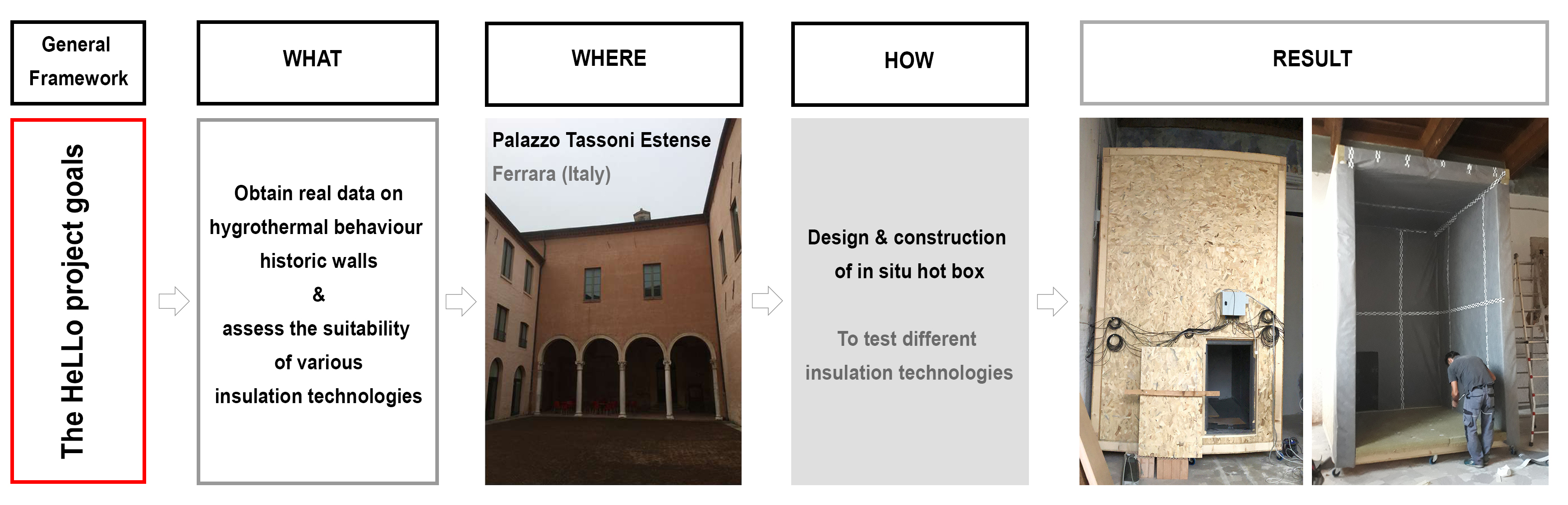
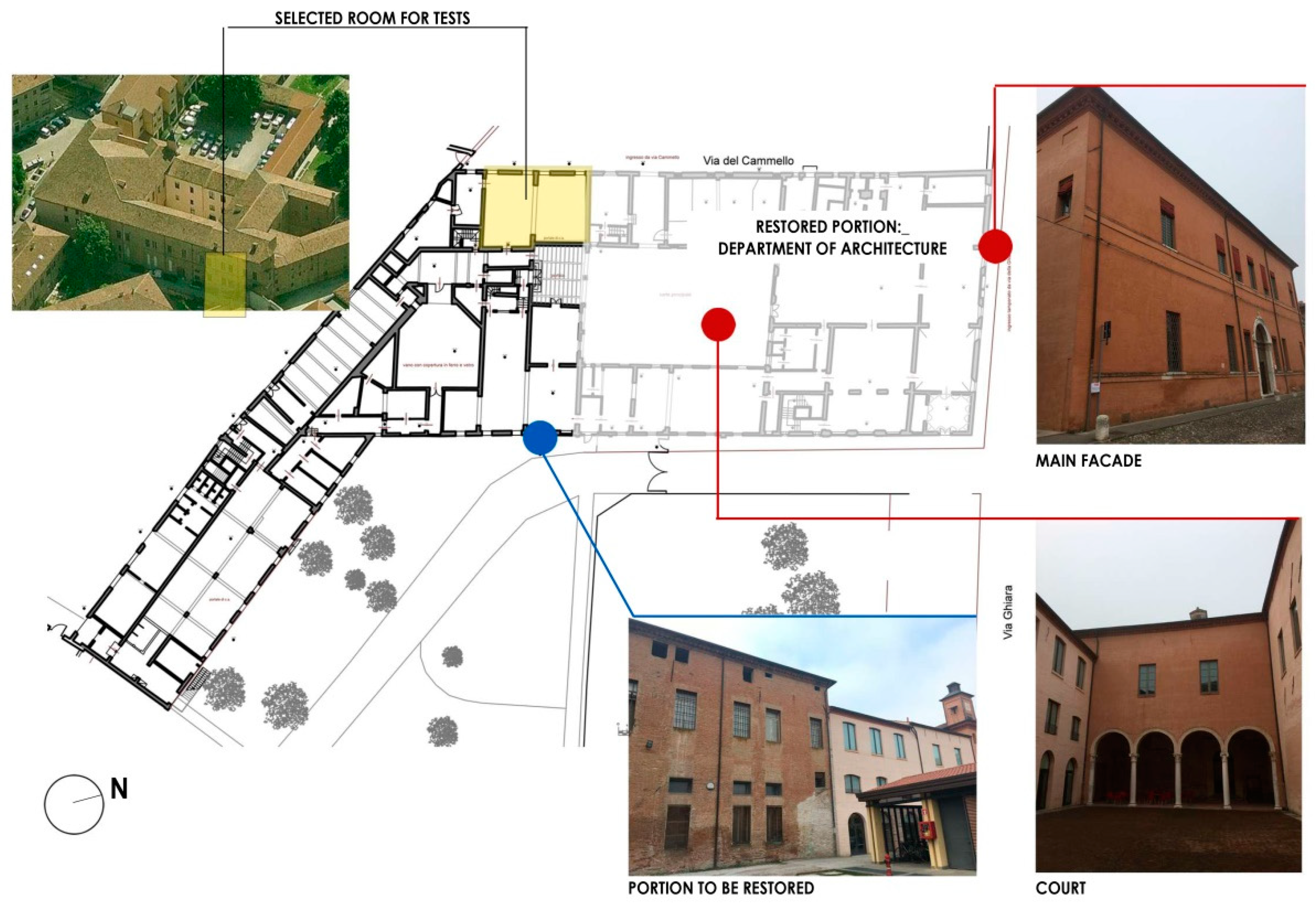
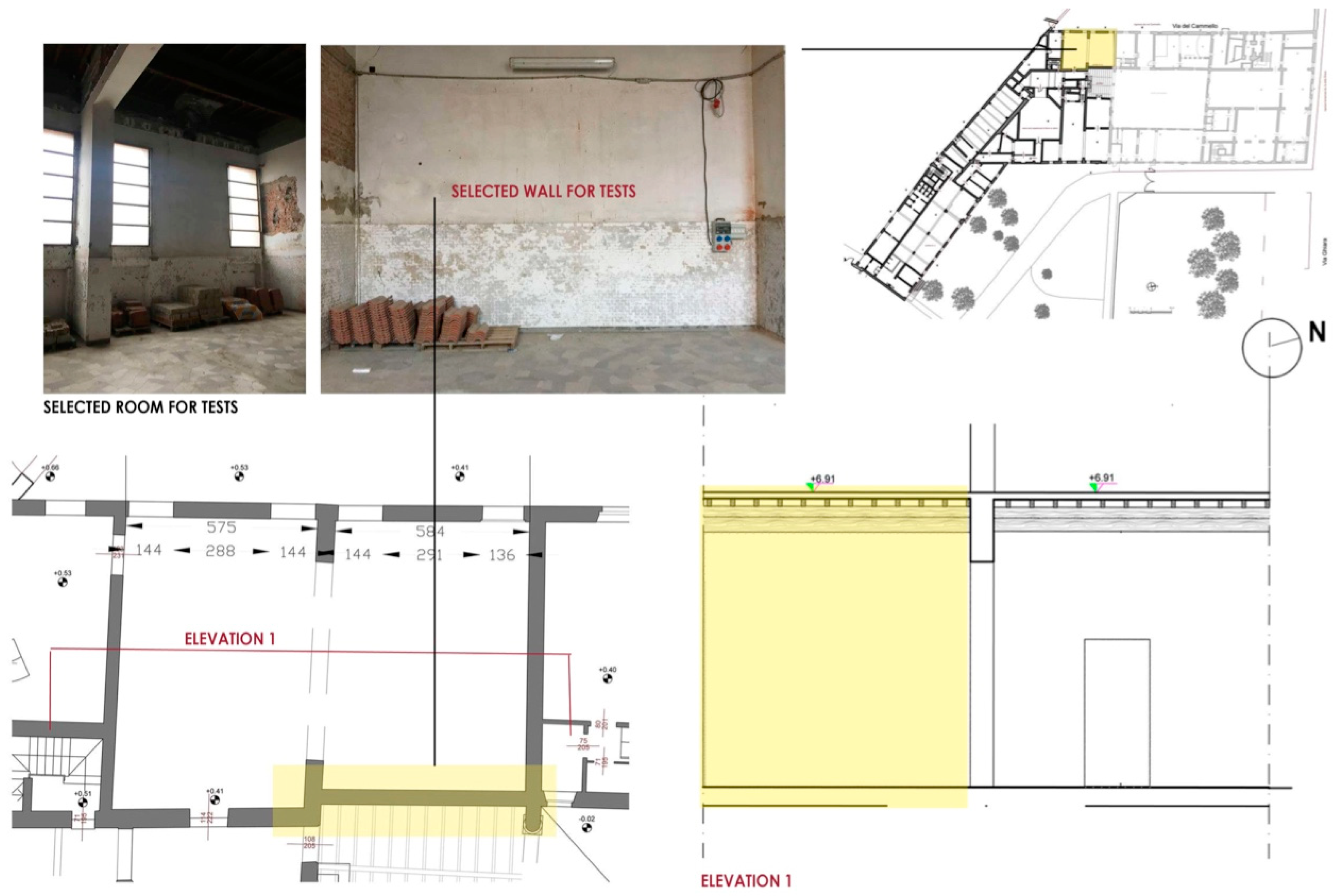
4. Case-Study Presentation and Experimental Methodology

4.1. Contextualization and Configuration of the Tested Wall

The in situ test was being performed in Palazzo Tassoni Estense in Ferrara, Italy. This 15th century listed building is part of a UNESCO site [86], with characteristics representative of many historic buildings. Since 1997, the Palazzo has been the subject of several studies, which resulted in an architecture project and a scientific restoration intervention [87]. The complex of the Palace is located in the NW part of a block, currently housing almost exclusively the Department of Architecture of the University of Ferrara, near the ancient walls of the city.
In order to provide a proper background, it is opportune to recall “that it was built within the Borso Addition (an area of urban expansion wanted by Borso d’Este, who was then the Duke of Ferrara)” during the mid-15th century, then “confiscated by Ercole I d’Este and gifted to the Tassoni Counts in 1476” [87] (p. 129). By 1491, in a letter to the Duke, “the architect Biagio Rossetti affirmed being in charge of the renovation works of the palace.” It “housed the Tassoni Estense family until 1858, when it was designated as the seat of the Provincial Psychiatric Hospital. (…) The mental institution remained active until the 1970s” [87] (p. 129).
The Palace was built in masonry bricks and it has considerable architectural interest, e.g., (i) “the main entrance from the street is made of decorated white marble”; (ii) “the perron, in the upper floor, has been restored and it preserves only partially its original features”; (iii) ”the access doors to the main hall are still the original and exquisite renaissance artifacts” [34] (p. 10).
The room (700 m3) and the wall under-study are part of this complex and are located on the ground floor of an area that has not been refurbished yet, currently unoccupied and without any HVAC system (Figure 1 and Figure 2).
Facing the challenge of assessing the hygrothermal behaviour of the historic wall, the authors’ option was twofold: (i) conditioning and buffering the openings of a 700 m3 space; or (ii) building an in situ chamber that simulated the conditions of a smaller room that still had as an external boundary, the original historic wall. The authors opted for the second hypothesis, both because of the sustainability of the experiment itself (less energy is required/wasted) either before the risks of the operation (limiting the intervention on the historic building, reduces the risks and impact on the heritage features).
Though the HFM method was probably the most internationally recognized and widely used method, it presented several disadvantages for the intended experiment. On one side, this method suggested high-temperature differences between the indoor and outdoor air (ΔTa). As a matter of fact, “[…] the increase in the measurement temperature difference between the indoor and outdoor environment can weaken the influence of the temperature fluctuation and decrease the test error” [68] (p. 49) but, unfortunately, this difference cannot always be guaranteed in a real field situation (outdoor climate cannot be controlled). On the other side, aiming at the authors’ future intention of testing indoor thermal solutions, the RH parameter could not be neglected, and the experience could not be limited to wall U-value measurement.
Due to all these premises, field restraints, and the final research goal, an in situ acclimatized box was built, aiming at simulating a ‘standard’ indoor environment (Ta ≈ 20 °C, RH ≈ 55%; in accordance with several standards/guidelines, e.g., EN ISO 7730 [88], EN ISO 13,788 [89], ISO 17772-1 [90]) that potentially guaranteed a satisfying ΔTa between the indoor face of the monitored wall and the external site condition (outdoor climate), ‘business as usual’ and that always allowed the collection of hygrothermal data of the wall behaviour (and, therefore, using combined T and RH sensors) [34].

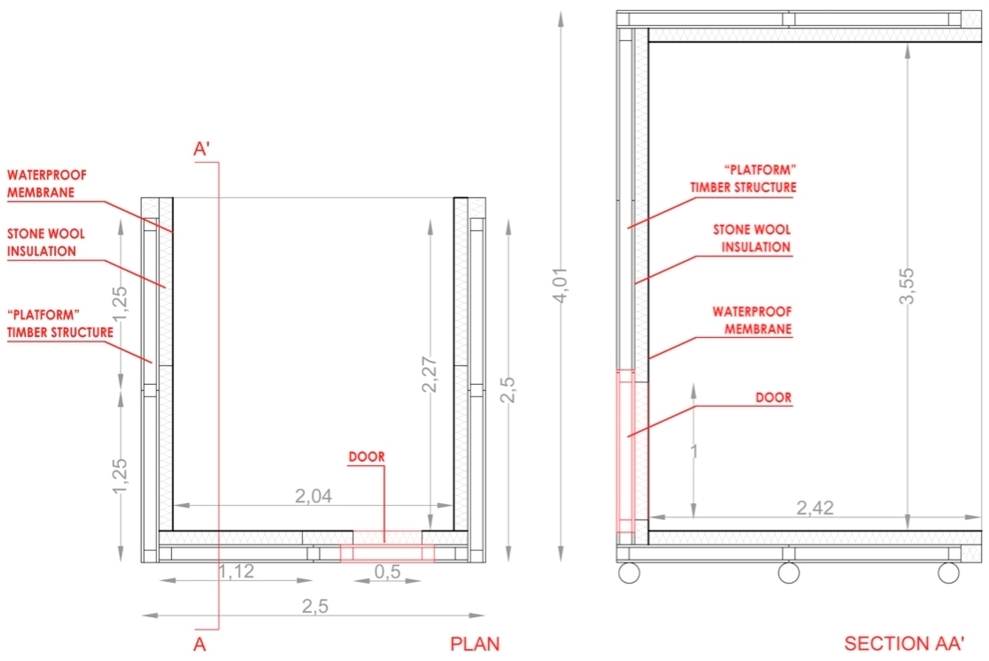
4.2. Design of the New Metering Hot Box

As stated earlier, in order to overcome field experiment restraints, the authors proposed a combined strategy between the in situ monitoring and hot box method to enhance robust measurement and reliable data acquisition. As in [70] (p. 747), the idea was that this simplified solution “[…] avoids the heavy equipment of the hot box method and overcomes outdoor and indoor thermal environment limitation of the HFM Method”. Moreover, it was also worth mentioning that often in situ measurement was not done because using the standard method ISO 9869, a measurement period of more than 10 days was normally required [91]. Using the proposed method, the monitoring campaign can be performed almost continuously or with very limited interruption periods.
One of the common characteristics of most metering boxes is their mobile base design. Anticipating future studies on different case studies, risks on the selected room where the monitoring campaign was initially foreseen, or given its own weight (≈700 kg), alike in [92], the newly developed metering box was intentionally provided with wheels thus that it could be more easily moved. Moreover, it was built of a modular timber structure to be more simply dismantled or size adjusted in the event it had to be moved to another room or building with other specifications. This feature, i.e., the box possibility of re-assemblage and re-usability, emphasized the experiment’s sustainability.
According to [70] (p. 752), for the SHB-HFM, the minimum box dimension should vary according to the different measurement walls. Considering this, for a wall thickness of 0.30 m it was recommended that the minimum box dimensions were about 1 m: i.e., for a wall thickness of 0.24 m or 0.360 m, for a ‘preferred’ temperature difference of 25 °C, the box dimension may vary between 0.7 m and 1.3 m [70] (Table 3, p. 755).
In the current study, authors have taken into account all these assumptions, but also the specificity of the field of the current and future case-studies: historic buildings, many times characterized by internal volumes with significant high ceilings. For this reason, the newly proposed box had dimensions significantly bigger than the minimum suggested by [70], closer to a climatic chamber than exactly a hot box, aiming at reproducing a fraction of a typical indoor volume of a Palazzo, for example.
The newly developed metering hot box used to perform the hygrothermal tests is depicted in Figure 3. This gross box size is 2.50 × 2.50 × 4.01 m, built with ‘platform system’ circa 0.13 m thick walls composed by two 0.018 oriented strand board (osb) panels mounted on a timber structure made of elements 0.09 × 0.09 m. To avoid thermal losses and maintain the setup temperature and humidity values, the 5 walls faces (including the pavement) were provided of 0.10 m high-density stone wool insulation material, then protected with a vapor barrier. The net size was 2.04 × 2.42 × 3.55 m (volume of the chamber).
Box dimensions were determined not only by the anticipated study of probable vertical heat stratification common in historic buildings often with high ceilings (see also Section 5.1), but also due to the favoured and anticipated study of at least 2 insulation systems put in parallel, as depicted in Figure 4, alike the experimental study developed by Kloseiko et al. [93]. In [93], the hygrothermal performance of an internally insulated brick wall was studied, with different insulation systems, measuring 1.00 m width each (this way, by placing sensors in the middle, a 0.50 m distance from each material border was assured).

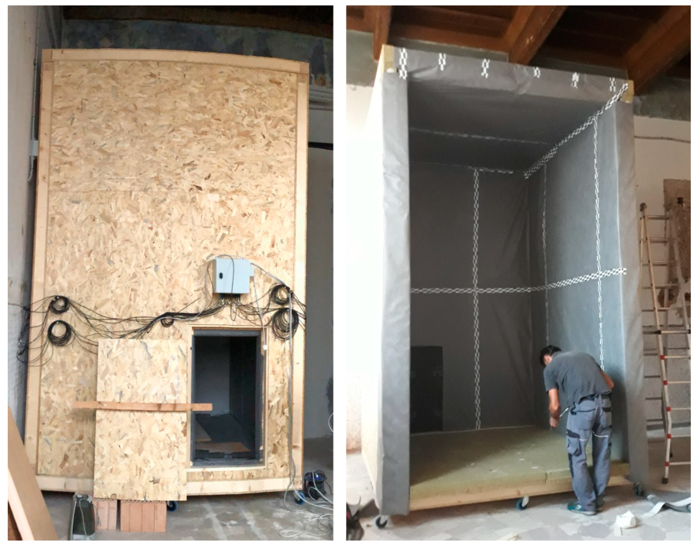
4.3. Construction of the Metering Box

One of the main objectives of the HeLLo project, besides the general scientific final goal to make actors of buildings sector aware of strengths and weaknesses of the most common energy retrofit technical solutions when applied to historic buildings [32], was the development of a very wide and structured program of dissemination The idea was to open the door of the laboratory to other different stakeholders and involve them in the project activities. Among this open Labs program, in the one called SchoolLab activity, in a unique didactical approach, students of the 2nd year of the Degree of Architecture were involved in the activity of the box constructing—Figure A1 in Appendix A unveils some of the steps of the box construction. During this phase, only the ‘outer-shell’ was executed (the platform frame structure), being later internally coated with 10 cm high-density stone wool, covered by a vapor barrier, Figure 5.

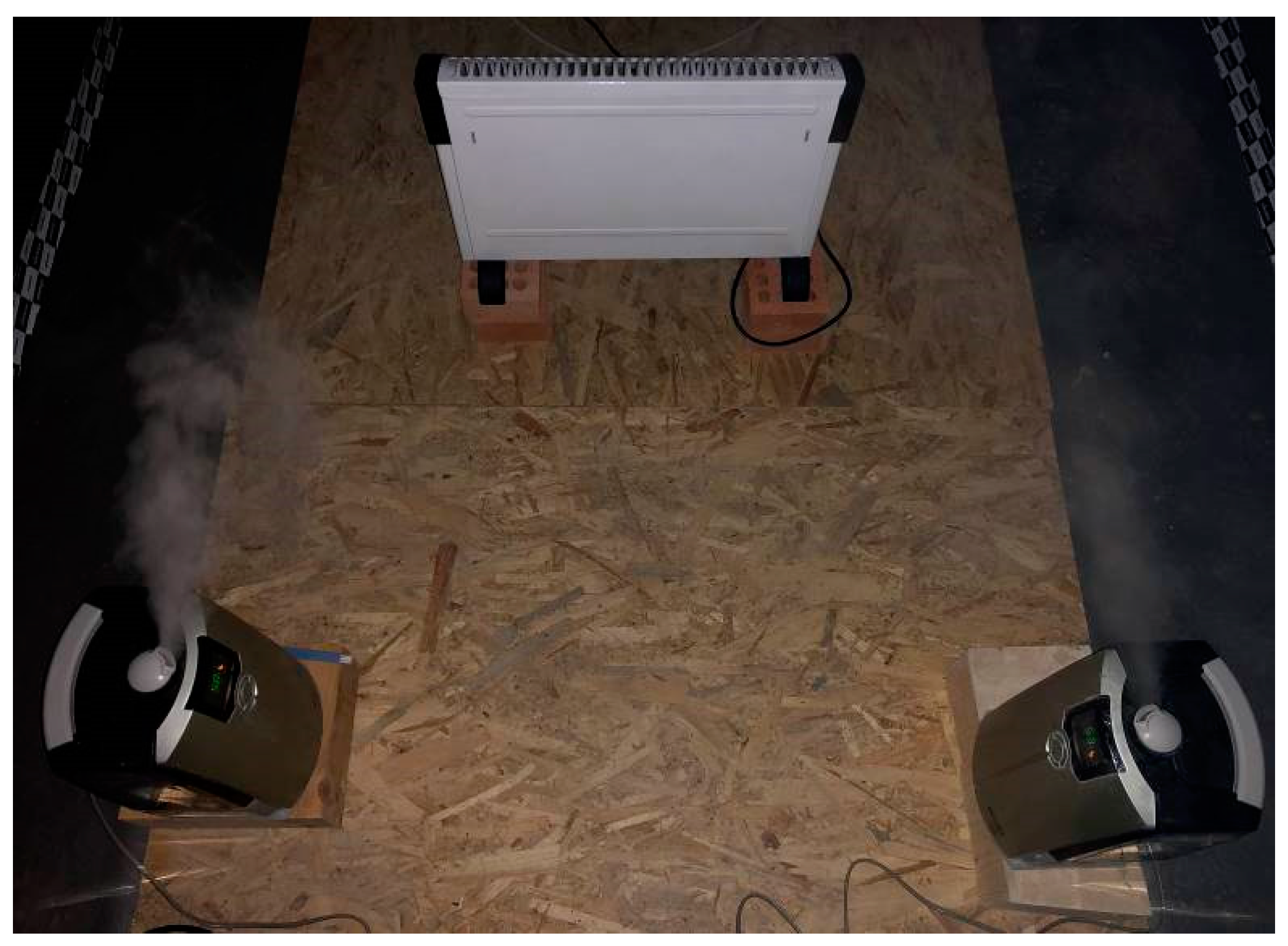
4.4. Monitoring System of the Metering Box

Monitoring the hygrothermal behaviour of historic building components was slightly more complex than in existing non-historic ones. As stated in [94] (p. 97), “[…] common mounting systems for long-term surface measurements are risky to original surfaces in historic buildings”, e.g., standard installation methods (e.g., adhesive bonds and sensors fixed to walls with holders and/or screws) might damage original surfaces when sensors are later removed. This assumption relates to cultural heritage protection requirements [95] of NDT or methods with the least damages [94].
The metering box was provided with a 2000 W heating convector (with 3 power levels), locally controlled by its own sensor (PID, as described below) and 2 ultrasonic humidifiers, (argo HYDRO digit), 30W/each, self-regulated, which guaranteed indoor air parameters at the desired setup conditions (T ≈ 20 °C, RH ≈ 55%), Figure 6.
In [34], authors presented an innovative measuring method for the hygrothermal assessment of historic walls. In the current study, the same low-cost and conservation compatible technology was also used to control the hygrothermal parameters of the metering box system. The air temperature and RH inside and outside the metering box were controlled by T-RH combined sensors. “These sensors are based on a capacitive polymer RH sensor and a PTA (Proportional to Absolute) integrated temperature sensor (Telaire T9602; Amphenol). They were IP67 certified to guarantee protection in a harsh environment. These sensors used a PDM output signal, and a low pass RC filter was needed to have a voltage signal to acquire hygrothermal data” [34] (p. 7). The sensors of the metering box were connected and managed by a data acquisition system based on a Master Slave configuration.
The initial version of the developed remote sensing technology [34] was upgraded and tuned to fit the current requirements of the HeLLo project. The T-RH measurement system was unchanged, and it was still based on Amphenol probes coupled with an RC lowpass filter, and readout of the analog values was performed by Analog Input Seneca devices with Modbus communication. Old thermostatic heating control was replaced with a more sophisticated Seneca module based on retroactive PID (Proportional, Integrative, Derivative) algorithm and coupled with a triac solid state relay. The temperature probe of the PID module was a PT100 class B. In order to keep the temperature constant inside the metering box, the PID control works on cycles of 120 seconds. Temperature trends were evaluated in terms of temperature integral of previous cycles and heat was activated for a fraction of cycle. The PID module was connected on the same Modbus net and can be configured and monitored by the same software that acquires T-RH values.
The acquisition software was updated, including readout and control of PID modules, and in order to have a configurable number of probes and readout modules, dedicated features were introduced. Substantial updates were done with the main control software. Some of the newly implemented features are listed below:
  • Email notification is sent hourly if everything works with a summary of all measurements, otherwise, every critical change in status is notified, with detailed information;
  • An hourly backup copy of raw data is performed on a local drive;
  • Daily processing of raw data is performed to produce more usable data files;
  • Web pages with a summary of system and measurement details are updated every minute and synchronized with an online web server. This allows us to have a simple view of status available on every device connected to the internet, like a PC and mobile device;
  • A protected local folder containing raw data backup and all pdf reports are synchronized with an external cloud.

5. Results and Discussion of the Conditions inside the Box

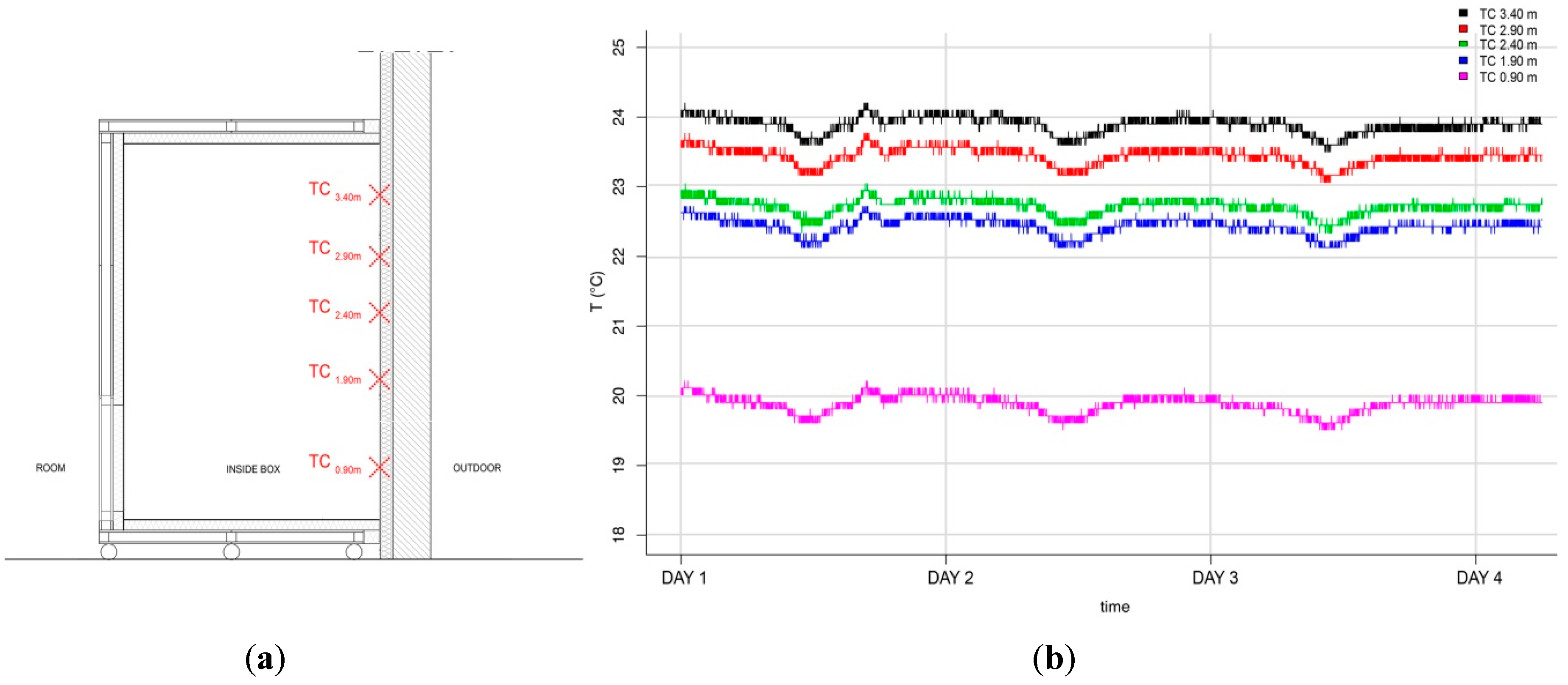
5.1. Preliminary Test for the Evaluation of Heat Stratifications

A simple test was performed to control vertical heat stratification inside the box. Five hand-made thermocouples (TC) with an accuracy of 0.5 °C (calibrated in the laboratory), were placed on the surface of the historic wall, between 0.90 m and 3.40 m from the floor to circa 0.50 m from the box boundaries (Figure 7a), during a four-day monitoring period. As shown in Figure 7b, between the highest TC (h = 3.40 m, in black) and the lowest one (h = 0.90 m, in pink) there was an average difference of 4 °C. This simple test has confirmed the anticipated heat stratification, common in historic buildings, justifying the height of the box.

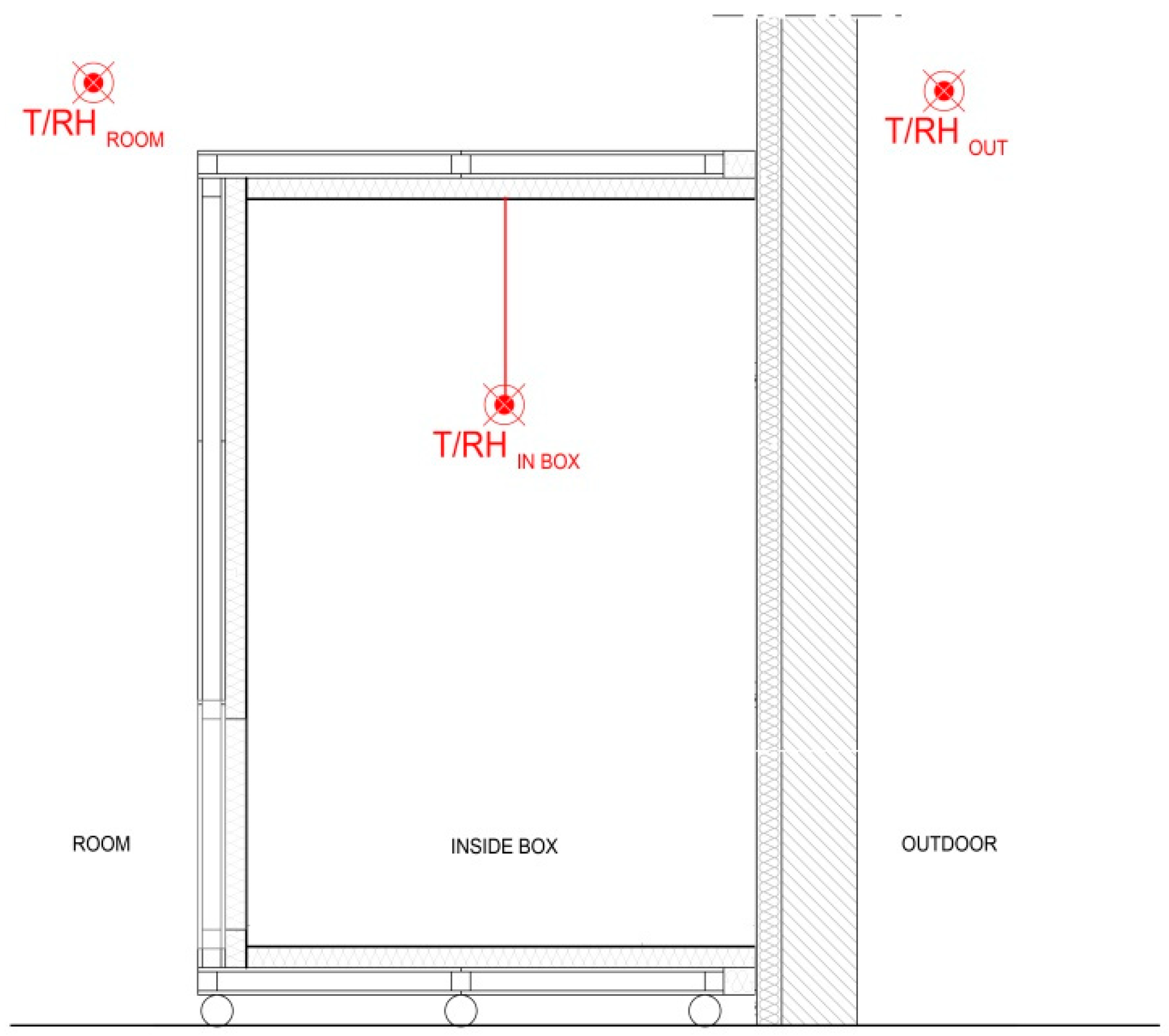
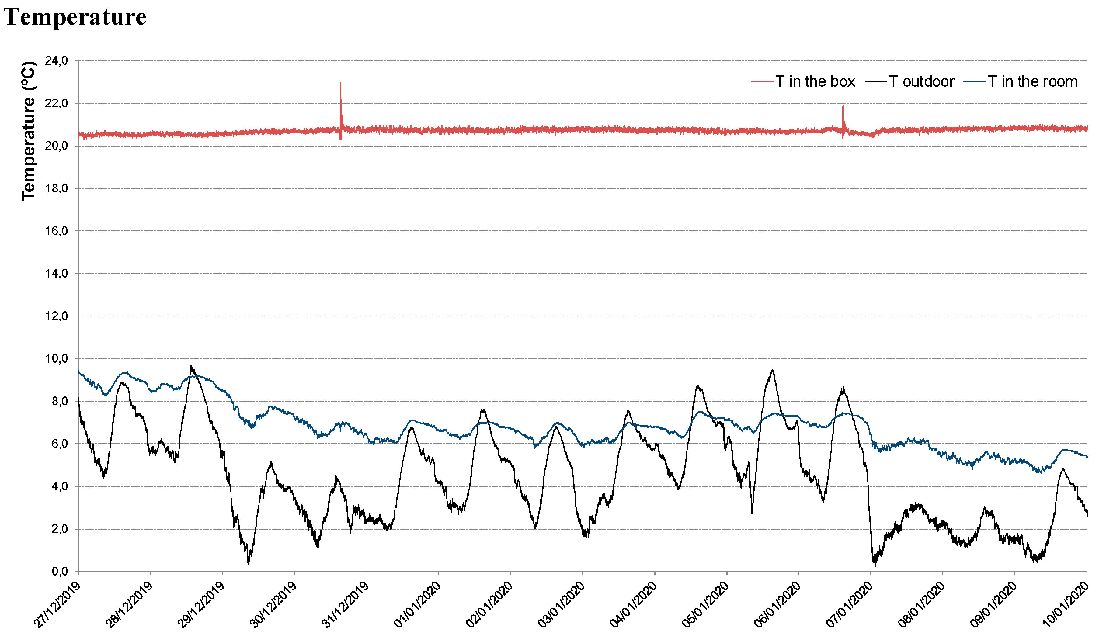
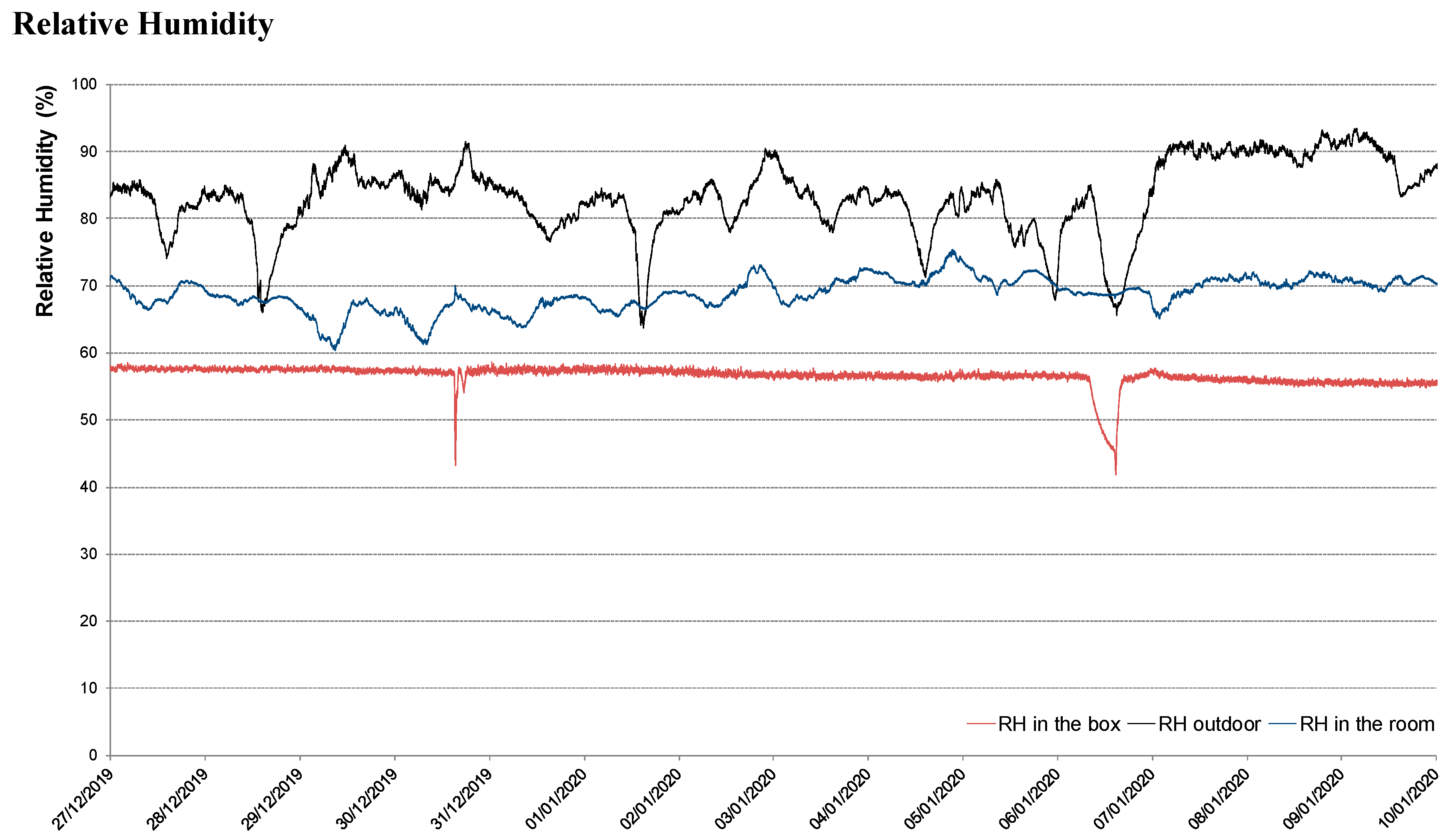
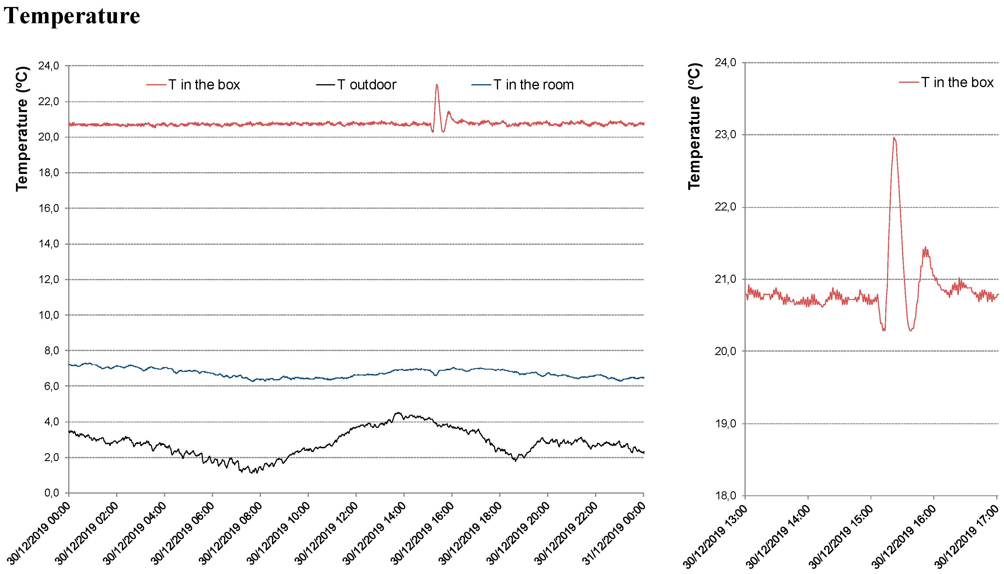
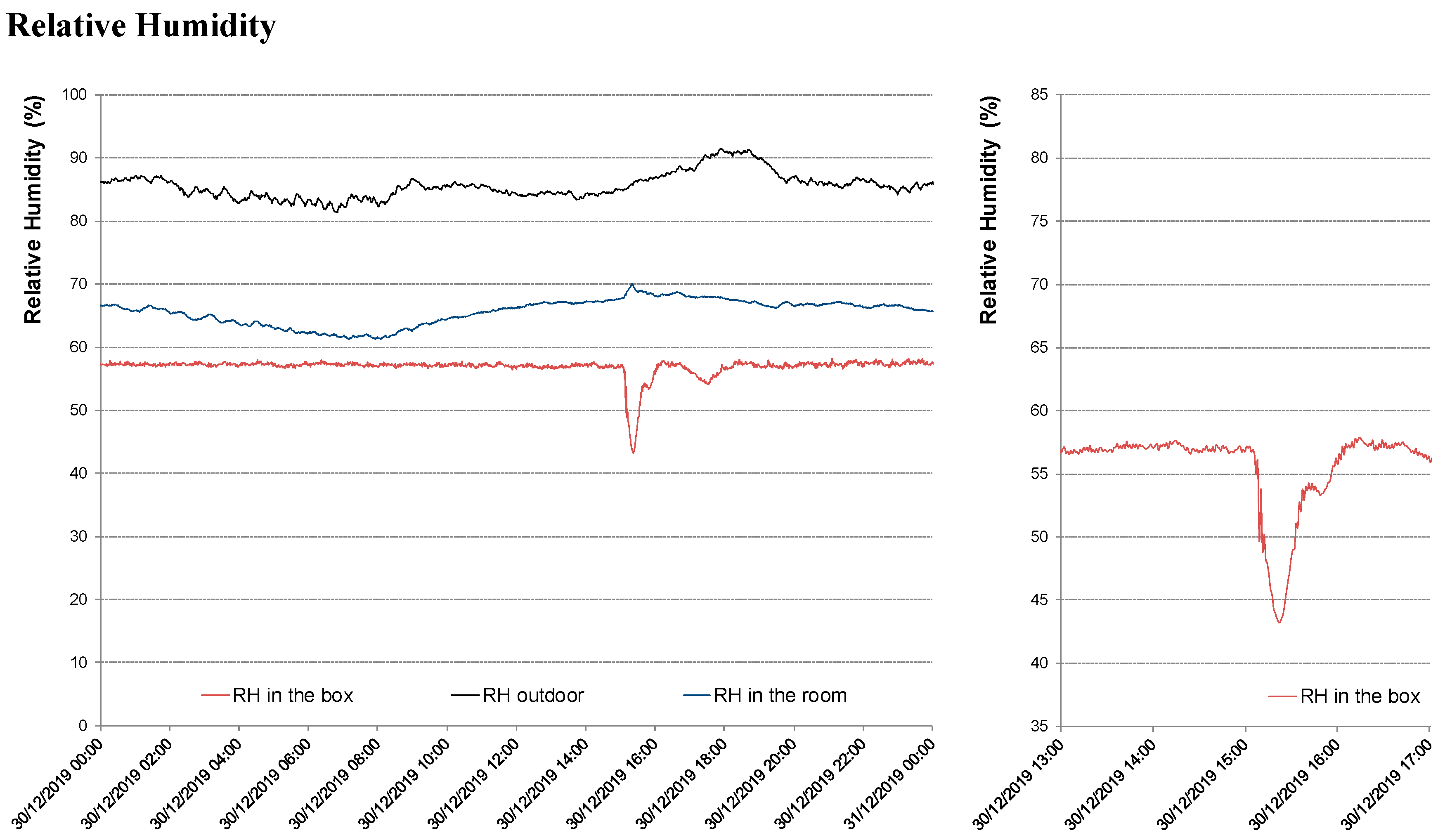
5.2. Validation of the Hygrothermal Set-Up

Figure 8 shows the distribution of the T-RH combined sensors (see Section 4.4) for the monitoring of the following environmental parameters (Ta and RH):
  • Of the outdoor climate conditions (T/RH OUT);
  • Of the non-refurbished and not heated room in which the box is located (T/RH ROOM);
  • Inside the metering box (T/RH IN BOX), placed in the center at circa 1.0 m from the top of the box.
The validation of the maintenance of the desired setup conditions was reached after the first period of tests and tuning (27 December 2019–10 January 2020). Figure 9 shows a recently monitored two-week period of a very stable indoor environment. Moreover, in the figure, two small peaks can be observed, brief in time and amplitude, corresponding to the moment of maintenance procedures of the monitoring campaign. In other words, the moments when the door of the box was opened, and the conditions of the air inside the box naturally mixed with those of the room. The insignificance of these events can be further observed in detail in Figure 10.
As declared, the door of the box was opened twice during this period, on the 30 December 2019 and 6 January 2020, i.e., the experiment might need to be controlled on-site up to once a week. Nonetheless, this action interferes with almost nothing with the continuity and stability of the indoor conditions. Looking at the most noticeable peak, registered on the 30th December, Figure 10, from the moment the door was opened, the indoor temperature suffered a maximum variation of 2.7 °C. Likewise, RH ∆max = 15%.
As shown in Figure 9, the outdoor climate in this winter period is quite varied. The same goes for the conditions of the room where the box is placed, which, as expected, were close to the outdoor conditions, less the thermal influence of the inertia of the historic building envelope. For the entire monitoring period (27 December 2019–10 January 2020), the conditions in the box were definitely stable, average T = 20.7 °C, average RH = 56.5%.

6. Conclusions and Outlook

The new developed device is absolutely disruptive in the field: until this moment, for similar studies, the developed in situ facilities addressed the wall thermal transmittance solely, neglecting the importance of the water vapor permeability factor on the overall wall performance. The feasibility of the new metering hot box has been verified by an in situ measurement for the hygrothermal survey of retrofit wall behaviour in a demonstration MSCA-IF project [32], creating a stable hygrothermal environment by the box. When compared to other boxes the new hot box presents other advantages compared to previous examples:
  • It allows long-term monitoring simulating a ‘real’ indoor environment (e.g., the study in [69] was proposed for short-time HFM measurements);
  • It contributes to minimizing biased results since it addresses both the thermal and hygric phenomena of the walls (e.g., in [68] (p. 49) authors recalled that the measured thermal transmittance results obtained in [69] were “55% higher than the design thermal transmittance and that the measurement error was attributed to high moisture”);
  • It is the first one of its kind addressing historic buildings—probably the type of buildings where data collection in situ is more urgent to be collected, considering that often the characteristics of the materials and their real performance are unknown;
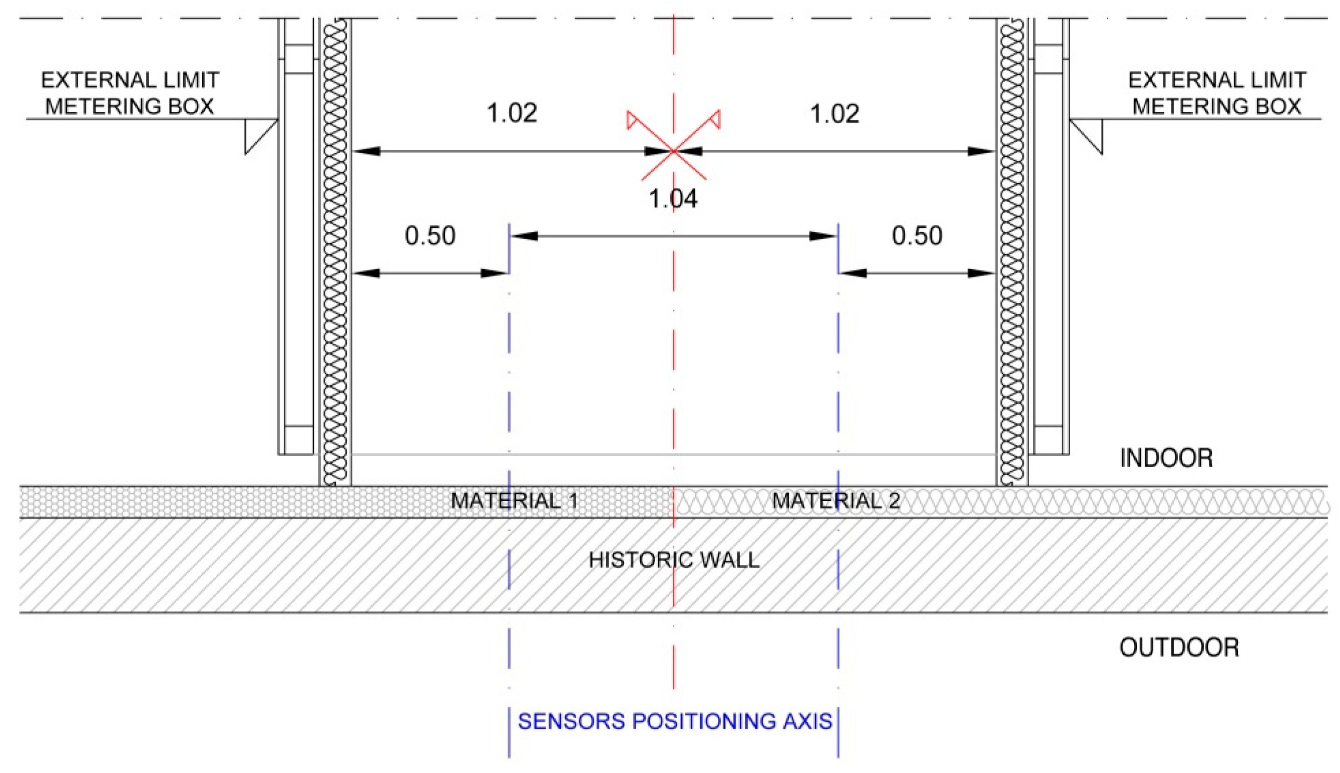
  • The singularity of addressing historic buildings justifies the box height. Its width was determined to allow future studies on the hygrothermal performances of internal thermal insulation (two materials can be tested in parallel);
  • Similar to a traditional hot box, it was provided with wheels to be more easily moved. In order to minimize the impact on the monitoring, for maintenance purposes, the box was provided with a back door (located on the opposite side where main parameters are being collected);
  • The box was built during an educational activity, involving students from a perspective of learning through practice, making the entire scientific process more inclusive.
One other significant advantage could be pointed out: the box re-usability (i.e., enhanced sustainability). As it is provided with wheels, it can be easily moved against another wall in the same room or, more importantly, due to its construction by modules, it can disassemble and used in other case studies. Lastly, it also allows the realization of in situ tests with different settings, for example, ‘stress test’.

Author Contributions

Authors are listed in alphabetical order. Conceptualization and methodology, M.C., L.D.P., E.L.; validation and formal analysis, M.A., M.C., L.D.P., R.M.; investigation, M.A., M.C., P.D., L.D.P.; data curation M.A., L.D.P., R.M.; supervision P.D.; writing, review, and editing: M.A., M.C., P.D., L.D.P., E.L. All authors have read and agreed to the published version of the manuscript.

Funding

The results presented in this paper are part of the HeLLo project that has received funding from the European Union’s Horizon 2020 research and innovation programme under the Marie Sklodowska-Curie grant agreement No 796712.

Acknowledgments

The authors acknowledge Giorgi Roberto, Lavorazione Legno and ROCKWOOL® Italia S.p.A. for the use of their materials and the contribution to the execution of the metering box.

Conflicts of Interest

The authors declare no conflict of interest. The funders had no role in the design of the study; in the collection, analyses, or interpretation of data; in the writing of the manuscript, or in the decision to publish the results.

Nomenclature

BESBuilding Energy SimulationNDT&ENon-Destructive Testing and Evaluation
CHCultural HeritageOSBOriented strand board
CHBCalibrated Hot Box PIDProportional, Integrative, Derivative
EUEuropean UnionφHeat flux (W⋅m−2)
GHBGuarded Hot BoxSHOSimple Hot Box
GHPGuarded Hot PlateTTemperature (°C)
HVACHeating, ventilation and Air conditioningTaAir Temperature (°C)
HeLLoHeritage energy Living Lab onsiteTCThermocouples
HFMHeat Flow Meter TCBTemperature Control Box
IRT Infrared Thermography TsSurface temperature
ITTInfrared Thermography TestingRHRelative Humidity (%)
NDTNon-Destructive TestingRHaAir Relative Humidity (%)
NDENon-Destructive Evaluation U-valueThermal transmittance (W/m2K)

Appendix A

Figure A1. Box construction during SchooLab activity with students (HeLLo [32]).
Energies 13 02950 g0a1

References

  1. European Commission. Directive 2012/27/Eu of the European Parliament and of the Council; 2012; 56p, Available online: http://eur-lex.europa.eu/legal-content/EN/TXT/PDF/?uri=CELEX:32012L0027&from=PT (accessed on 28 May 2020).
  2. Filippi, M. Remarks on the green retrofitting of historic buildings in Italy. Energy Build. 2015, 95, 15–22. [Google Scholar] [CrossRef]
  3. European Commission. European Commission > Energy > Topics > Energy Efficiency > Buildings. Available online: https://ec.europa.eu/energy/en/topics/energy-efficiency/energy-performance-of-buildings/energy-performance-buildings-directive (accessed on 8 June 2016).
  4. Buildingradar.com. Europe Construction Market Forecast from 2015 to 2020. Available online: https://buildingradar.com/construction-blog/european-construction-market-forecast/ (accessed on 26 June 2016).
  5. Phoenix, T. Lessons learned: ASHRAE’s approach in the refurbishment of historic and existing buildings. Energy Build. 2015, 95, 13–14. [Google Scholar] [CrossRef]
  6. Edinburgh World Heritage. Old and New Towns of Edinburgh World Heritage Site Management Plan 2017–2022; Edinburgh, UK, 2017; Available online: https://ewh.org.uk/plan/assets/Management-Plan-2018.pdf (accessed on 28 May 2020).
  7. Litti, G.; Khoshdel, S.; Audenaert, A.; Braet, J. Hygrothermal performance evaluation of traditional brick masonry in historic buildings. Energy Build. 2015, 105, 393–411. [Google Scholar] [CrossRef]
  8. Historic England. Energy Efficiency and Historic Buildings: Insulating Solid Walls; Historic England: London, UK, 2012; pp. 1–61. [Google Scholar] [CrossRef]
  9. Lucchi, E. Thermal transmittance of historical stone masonries: A comparison among standard, calculated and measured data. Energy Build. 2017, 151, 393–405. [Google Scholar] [CrossRef]
  10. Lucchi, E. Thermal transmittance of historical brick masonries: A comparison among standard data, analytical calculation procedures, and in situ heat flow meter measurements. Energy Build. 2017, 134, 171–184. [Google Scholar] [CrossRef]
  11. Peak District National Park. Conserving Your Historic Building. Sustainability and Historic Buildings: A Guide for Owners and Occupiers. Available online: http://www.special-eu.org/assets/uploads/Sustainability_and_Historicbuildings_by_Peak_District.pdf (accessed on 28 May 2020).
  12. Raftery, C. Energy Performance in Protected Structures: Planning implications and grants. In Energy Efficiency in Historic Houses; Irish Georgian Society: Dublin, Ireland, 2013; pp. 7–18. ISBN 978-0-9545691-4-3. Available online: https://www.igs.ie/uploads/Energy_Efficiency_in_Historic_Houses.pdf (accessed on 28 May 2020).
  13. Khoury, J.; Alameddine, Z.; Hollmuller, P. Understanding and bridging the energy performance gap in building retrofit. Energy Procedia 2017, 122, 217–222. [Google Scholar] [CrossRef]
  14. Zou, P.X.W.; Xu, X.; Sanjayan, J.; Wang, J. Review of 10 years research on building energy performance gap: Life-cycle and stakeholder perspectives. Energy Build. 2018, 178, 165–181. [Google Scholar] [CrossRef]
  15. Bortoluzzi, D.; Costa, A.; Casciati, S. Reducing Energy Performance Gap in Buildings—Built2Spec Project Solution. Proceedings 2017, 1, 640. [Google Scholar] [CrossRef] [Green Version]
  16. Bourdeau, M.; Guo, X.; Nefzaoui, E. Buildings energy consumption generation gap: A post-occupancy assessment in a case study of three higher education buildings. Energy Build. 2018, 159, 600–611. [Google Scholar] [CrossRef] [Green Version]
  17. Built2Spec. D1.2 Performance Gap and Its Assessment Methodology in Built2Spec Project. 2015. Available online: http://built2spec-project.eu/wp-content/uploads/2016/06/Built2Spec_Performance_gap_assessment_methodology_part_1.pdf (accessed on 28 May 2020).
  18. Barthelmes, V.M.; Becchio, C.; Fabi, V.; Corgnati, S.P. Occupant behaviour lifestyles and effects on building energy use: Investigation on high and low performing building features. Energy Procedia 2017, 140, 93–101. [Google Scholar] [CrossRef] [Green Version]
  19. Soares, N.; Bastos, J.; Pereira, L.D.; Soares, A.; Amaral, A.R.; Asadi, E.; Rodrigues, E.; Lamas, F.B.; Monteiro, H.; Lopes, M.A.R.; et al. A review on current advances in the energy and environmental performance of buildings towards a more sustainable built environment. Renew. Sustain. Energy Rev. 2017, 77, 845–860. [Google Scholar] [CrossRef]
  20. van Dronkelaar, C.; Dowson, M.; Spataru, C.; Mumovic, D. A Review of the Regulatory Energy Performance Gap and Its Underlying Causes in Non-domestic Buildings. Front. Mech. Eng. 2016, 1, 1–14. [Google Scholar] [CrossRef] [Green Version]
  21. Calzolari, M.; Davoli, P. Instruments for the calculation of energy performance in historical buildings. Limits of applicability and tuning proposal. SMC Sustain. Mediterr. Constr. L. Cult. Res. Technol. Mag. 2018, 1, 108–114. [Google Scholar]
  22. Adhikari, R.S.; Lucchi, E.; Pracchi, V. Energy modelling of historic buildings: Applicability, problems and compared results. In Proceedings of the 3rd European Workshop on Cultural Heritage Protection (EWCHP): Taking Care of Our Treasures, Bolzano, Italy, 16–17 September 2013; pp. 119–125. [Google Scholar]
  23. Evangelisti, L.; Battista, G.; Guattari, C.; Basilicata, C.; de Lieto Vollaro, R. Analysis of two models for evaluating the energy performance of different buildings. Sustainability 2014, 6, 5311–5321. [Google Scholar] [CrossRef] [Green Version]
  24. Rye, C. A Short Paper on the Conventions and Standards that Govern the Understanding of Heat Loss in Traditional Buildings. 2012. Available online: http://www.sdfoundation.org.uk/downloads/STBA-Short-Paper-on-heat-loss-FINAL.pdf (accessed on 28 May 2020).
  25. Akkurt, G.G.; Aste, N.; Borderon, J.; Buda, A.; Calzolari, M.; Chung, D.; Costanzo, V.; Del Pero, C.; Evola, G.; Huerto-Cardenas, H.E.; et al. Dynamic thermal and hygrometric simulation of historical buildings: Critical factors and possible solutions. Renew. Sustain. Energy Rev. 2020, 118, 109509. [Google Scholar] [CrossRef]
  26. Calzolari, M. Prestazione Energetica Delle Architetture Storiche: Sfide e Soluzioni. Analisi dei Metodi di Calcolo per la Definizione del Comportamento Energetico; Franco Angelli: Milano, Italy, 2016; ISBN 9788891740885. [Google Scholar]
  27. Belpoliti, V.; Bizzarri, G.; Boarin, P.; Calzolari, M.; Davoli, P. A parametric method to assess the energy performance of historical urban settlements. Evaluation of the current energy performance and simulation of retrofit strategies for an Italian case study. J. Cult. Herit. 2018, 30, 155–167. [Google Scholar] [CrossRef]
  28. Mantesi, E.; Hopfe, C.J.; Cook, M.J.; Glass, J.; Strachan, P. The modelling gap: Quantifying the discrepancy in the representation of thermal mass in building simulation. Build. Environ. 2018, 131, 74–98. [Google Scholar] [CrossRef] [Green Version]
  29. Pérez-Lombard, L.; Ortiz, J.; Coronel, J.F.; Maestre, I.R. A review of HVAC systems requirements in building energy regulations. Energy Build. 2011, 43, 255–268. [Google Scholar] [CrossRef]
  30. Dias Pereira, L.; Bispo Lamas, F.; Gameiro da Silva, M. Improving energy use in schools: From IEQ towards energy-efficient planning—method and in-field application to two case studies. Energy Effic. 2019, 12, 1253–1277. [Google Scholar] [CrossRef]
  31. Rhodes, J.D.; Stephens, B.; Webber, M.E. Using energy audits to investigate the impacts of common air-conditioning design and installation issues on peak power demand and energy consumption in Austin, Texas. Energy Build. 2011, 43, 3271–3278. [Google Scholar] [CrossRef]
  32. HeLLo EU H2020 MSCA-IF-ES HeLLo Project. 2019. Available online: https://cordis.europa.eu/project/rcn/215475/factsheet/en (accessed on 7 April 2019).
  33. Soares, N.; Martins, C.; Gonçalves, M.; Santos, P.; Simões da Silva, L.; Costa, J.J. Laboratory and in-situ non-destructive methods to evaluate the thermal transmittance and behaviour of walls, windows, and construction elements with innovative materials: A review. Energy Build. 2019, 182, 88–110. [Google Scholar] [CrossRef]
  34. Lucchi, E.; Dias Pereira, L.; Andreotti, M.; Malaguti, R.; Cennamo, D.; Calzolari, M.; Frighi, V. Development of a Compatible, Low Cost and High Accurate Conservation Remote Sensing Technology for the Hygrothermal Assessment of Historic Walls. Electronics 2019, 8, 1–20. [Google Scholar] [CrossRef] [Green Version]
  35. International Organization for Standardization (ISO). ISO 7345:2018. In Thermal Performance of Buildings and Building Components—Physical Quantities and Definitions; ISO: Geneva, Switzerland, 2018. [Google Scholar]
  36. International Organization for Standardization (ISO). ISO 8301:1991. In Thermal Insulation—Determination of Steady-State Thermal Resistance and Related Properties—Heat Flow Meter Apparatus; ISO: Geneva, Switzerland, 1991. [Google Scholar]
  37. International Organization for Standardization (ISO). ISO 9869-1:2014. In Thermal Insulation. Building Elements. In Situ Measurement of Thermal Resistance and Thermal Transmittance—Part 1: Heat Flow Meter Method; ISO: Geneva, Switzerland, 2014. [Google Scholar]
  38. Santos, P.; Gonçalves, M.; Martins, C.; Soares, N.; Costa, J.J. Thermal transmittance of lightweight steel framed walls: Experimental versus numerical and analytical approaches. J. Build. Eng. 2019, 25, 100776. [Google Scholar] [CrossRef]
  39. International Organization for Standardization (ISO). ISO 10880:2017. In Non-Destructive Testing—Infrared Thermography Testing—General Principles; ISO: Geneva, Switzerland, 2017. [Google Scholar]
  40. International Organization for Standardization (ISO). ISO 6781:1983. In Thermal Insulation—Qualitative Detection of Thermal Irregularities in Building Envelopes—Infrared Method; ISO: Geneva, Switzerland, 1983. [Google Scholar]
  41. International Organization for Standardization (ISO). ISO 8990:1994. In Thermal Insulation—Determination of Steady-State Thermal Transmission Properties—Calibrated and Guarded Hot Box; ISO: Geneva, Switzerland, 1994. [Google Scholar]
  42. Asdrubali, F.; Baldinelli, G. Thermal transmittance measurements with the hot box method: Calibration, experimental procedures, and uncertainty analyses of three different approaches. Energy Build. 2011, 43, 1618–1626. [Google Scholar] [CrossRef]
  43. Bienvenido-Huertas, D.; Moyano, J.; Marín, D.; Fresco-Contreras, R. Review of in situ methods for assessing the thermal transmittance of walls. Renew. Sustain. Energy Rev. 2019, 102, 356–371. [Google Scholar] [CrossRef]
  44. Sala, J.M.; Urresti, A.; Martín, K.; Flores, I.; Apaolaza, A. Static and dynamic thermal characterisation of a hollow brick wall: Tests and numerical analysis. Energy Build. 2008, 40, 1513–1520. [Google Scholar] [CrossRef]
  45. Giorgio, P.; De Carli, M. A measuring campaign of thermal conductance in situ and possible impacts on net energy demand in buildings. Energy Build. 2013, 59, 29–36. [Google Scholar] [CrossRef]
  46. Nardi, I.; Lucchi, E.; de Rubeis, T.; Ambrosini, D. Quantification of heat energy losses through the building envelope: A state-of-the-art analysis with critical and comprehensive review on infrared thermography. Build. Environ. 2018, 146, 190–205. [Google Scholar] [CrossRef] [Green Version]
  47. Lucchi, E. Applications of the infrared thermography in the energy audit of buildings: A review. Renew. Sustain. Energy Rev. 2018, 82, 3077–3090. [Google Scholar] [CrossRef]
  48. International Organization for Standardization (ISO). ISO 8302:1991. In Thermal Insulation—Determination of Steady-State Thermal Resistance and Related Properties—Guarded Hot Plate Apparatus; ISO: Geneva, Switzerland, 1991. [Google Scholar]
  49. ASTM International (American Society for Testing and Materials). ASTM C177—19. In Standard Test Method for Steady-State Heat Flux Measurements and Thermal Transmission Properties by Means of the Guarded-Hot-Plate Apparatus; ASTM: West Conshohhocken, PA, USA, 2019. [Google Scholar]
  50. Reddy, K.S.; Jayachandran, S. Investigations on design and construction of a square guarded hot plate (SGHP) apparatus for thermal conductivity measurement of insulation materials. Int. J. Therm. Sci. 2017, 120, 136–147. [Google Scholar] [CrossRef]
  51. Kobari, T.; Okajima, J.; Komiya, A.; Maruyama, S. Development of guarded hot plate apparatus utilizing Peltier module for precise thermal conductivity measurement of insulation materials. Int. J. Heat Mass Transf. 2015, 91, 1157–1166. [Google Scholar] [CrossRef]
  52. Sanjaya, C.S.; Wee, T.-H.; Tamilselvan, T. Regression analysis estimation of thermal conductivity using guarded-hot-plate apparatus. Appl. Therm. Eng. 2011, 31, 1566–1575. [Google Scholar] [CrossRef]
  53. ASTM International (American Society for Testing and Materials). ASTM C1363-19. In Standard Test Method for Thermal Performance of Building Materials and Envelope Assemblies by Means of a Hot Box Apparatus; ASTM: West Conshohhocken, PA, USA, 2019. [Google Scholar]
  54. European Committee for Standardization (CEN). EN 1934:1998 Thermal Performance of Buildings—Determination of Thermal Resistance by Hot Box Method Using Heat Flow Meter—Masonry; CEN: Brussels, Belgium, 1998. [Google Scholar]
  55. Interstate Standard of Russian Federation (ISRF). Standard GOST 26602.1-99. In Windows and Doors. Methods of Determination of Resistance of Thermal Transmission; ISFR: Moscow, Russia, 1999. [Google Scholar]
  56. Vereecken, E.; Roels, S. A comparison of the hygric performance of interior insulation systems: A hot box-cold box experiment. Energy Build. 2014, 80, 37–44. [Google Scholar] [CrossRef]
  57. Byrne, A.; Byrne, G.; Robinson, A. Compact facility for testing steady and transient thermal performance of building walls. Energy Build. 2017, 152, 602–614. [Google Scholar] [CrossRef] [Green Version]
  58. Cucumo, M.; De Rosa, A.; Ferraro, V.; Kaliakatsos, D.; Marinelli, V. A method for the experimental evaluation in situ of the wall conductance. Energy Build. 2006, 38, 238–244. [Google Scholar] [CrossRef]
  59. Han, J.; Lu, L.; Peng, J.; Yang, H. Performance of ventilated double-sided PV façade compared with conventional clear glass façade. Energy Build. 2013, 56, 204–209. [Google Scholar] [CrossRef]
  60. Cattarin, G.; Causone, F.; Kindinis, A.; Pagliano, L. Outdoor test cells for building envelope experimental characterisation—A literature review. Renew. Sustain. Energy Rev. 2016, 54, 606–625. [Google Scholar] [CrossRef] [Green Version]
  61. Silva, T.; Vicente, R.; Rodrigues, F.; Samagaio, A.; Cardoso, C. Development of a window shutter with phase change materials: Full scale outdoor experimental approach. Energy Build. 2015, 88, 110–121. [Google Scholar] [CrossRef]
  62. Young, C.-H.; Chen, Y.-L.; Chen, P.-C. Heat insulation solar glass and application on energy efficiency buildings. Energy Build. 2014, 78, 66–78. [Google Scholar] [CrossRef]
  63. Qahtan, A.; Keumala, N.; Rao, S.P.; Abdul-Samad, Z. Experimental determination of thermal performance of glazed façades with water film, under direct solar radiation in the tropics. Build. Environ. 2011, 46, 2238–2246. [Google Scholar] [CrossRef]
  64. Gao, Y.; Roux, J.J.; Teodosiu, C.; Zhao, L.H. Reduced linear state model of hollow blocks walls, validation using hot box measurements. Energy Build. 2004, 36, 1107–1115. [Google Scholar] [CrossRef]
  65. Kus, H.; Özkan, E.; Göcer, Ö.; Edis, E. Hot box measurements of pumice aggregate concrete hollow block walls. Constr. Build. Mater. 2013, 38, 837–845. [Google Scholar] [CrossRef]
  66. Baldwin, C.; Cruickshank, C.A.; Schiedel, M.; Conley, B. Comparison of steady-state and in-situ testing of high thermal resistance walls incorporating vacuum insulation panels. Energy Procedia 2015, 78, 3246–3251. [Google Scholar] [CrossRef] [Green Version]
  67. Peng, C.; Wu, Z. In situ measuring and evaluating the thermal resistance of building construction. Energy Build. 2008, 40, 2076–2082. [Google Scholar] [CrossRef]
  68. Meng, X.; Gao, Y.; Wang, Y.; Yan, B.; Zhang, W.; Long, E. Feasibility experiment on the simple hot box-heat flow meter method and the optimization based on simulation reproduction. Appl. Therm. Eng. 2015, 83, 48–56. [Google Scholar] [CrossRef]
  69. Zhu, X.F.; Li, L.P.; Yin, X.B.; Zhang, S.H.; Wang, Y.; Liu, W.; Zheng, L. An in-situ test apparatus of heat transfer coefficient for building envelope. Build. Energy Effic. 2012, 256, 57–60. Available online: http://en.cnki.com.cn/Article_en/CJFDTotal-FCYY201206018.htm (accessed on 28 May 2020).
  70. Meng, X.; Luo, T.; Gao, Y.; Zhang, L.; Shen, Q.; Long, E. A new simple method to measure wall thermal transmittance in situ and its adaptability analysis. Appl. Therm. Eng. 2017, 122, 747–757. [Google Scholar] [CrossRef]
  71. EN 15758:2010. Conservation Of Cultural Property—Procedures and Instruments for Measuring Temperatures of the Air and the Surfaces of Objects; CEN: Brussels, Belgium, 2010. [Google Scholar]
  72. EN 16242. EN 16242 Conservation of Cultural Heritage—Procedures and Instruments for Measuring Humidity in the Air and Moisture Exchanges between Air and Cultural Property; CEN: Brussels, Belgium, 2012. [Google Scholar]
  73. Ente Italiano di Normazione (UNI). UNI 10829. In Beni di Interesse Storico e Artistico—Condizioni Ambientali di Conservazione—Misurazione ed Analisi; UNI: Milano, Italy, 1999. [Google Scholar]
  74. European Committee for Standardization (CEN). Standard CEN/TC 346—Conservation of Cultural Heritage; CEN: Brussels, Belgium, 2009. [Google Scholar]
  75. European Committee for Standardization (CEN). EN 15757:2010 Conservation of Cultural Property—Specifications for Temperature and Relative Humidity to Limit Climate-Induced Mechanical Damage in Organic Hygroscopic Materials; 2010; Available online: http://shop.bsigroup.com/ProductDetail?pid=000000000030173518 (accessed on 28 May 2020).
  76. European Committee for Standardization (CEN). CEN UNI EN 15759-1 (2012) (English). In Conservation of Cultural Property—Indoor Climate—Part 1: Guidelines for Heating Churches, Chapels and Other Places of Worship; CEN: Brussels, Belgium, 2012. [Google Scholar]
  77. Ente Nazionale Italiano di Unificazione (UNI). UNI 10969. In Beni Culturali. Principi Generali per la Scelta e il Controllo del Microclima per la Conservazione; UNI: Milano, Italy, 2002. [Google Scholar]
  78. Ente Nazionale Italiano di Unificazione (UNI). UNI 10586. In Condizioni Climatiche per Ambienti di Conservazione di Documenti Grafici e Caratteristiche Degli Alloggiamenti; UNI: Milano, Italy, 1999. [Google Scholar]
  79. Camuffo, D. Microclimate for Cultural Heritage: Conservation, Restoration, and Maintenance of Indoor and Outdoor Monuments, 2nd ed.; Elsevier: Amsterdam, The Netherlands, 2014; ISBN 9780444632968. [Google Scholar] [CrossRef]
  80. Walker, R.; Pavía, S.; Dalton, M. Measurement of moisture content in solid brick walls using timber dowel. Mater. Struct. 2016, 49, 2549–2561. [Google Scholar] [CrossRef]
  81. European Committee for Standardization (CEN). Standard prEN 16682. In Conservation of Cultural Heritage. Guide to the Measurements of Moisture Content in Materials Constituting Movable and Immovable Cultural Heritage; CEN: Brussels, Belgium, 2013. [Google Scholar]
  82. Ente Nazionale Italiano di Unificazione (UNI). UNI 11085. In Beni Culturali—Materiali Lapidei Naturali ed Artificiali—Determinazione del Contenuto D’acqua: Metodo Ponderale; UNI: Milano, Italy, 2003. [Google Scholar]
  83. Odgaard, T.; Bjarløv, S.P.; Rode, C. Interior insulation—Experimental investigation of hygrothermal conditions and damage evaluation of solid masonry façades in a listed building. Build. Environ. 2018, 129, 1–14. [Google Scholar] [CrossRef] [Green Version]
  84. Walker, R.; Pavía, S. Thermal and moisture monitoring of an internally insulated historic brick wall. Build. Environ. 2018, 133, 178–186. [Google Scholar] [CrossRef]
  85. Hansen, T.K.; Bjarløv, S.P.; Peuhkuri, R.H.; Harrestrup, M. Long term in situ measurements of hygrothermal conditions at critical points in four cases of internally insulated historic solid masonry walls. Energy Build. 2018, 172, 235–248. [Google Scholar] [CrossRef]
  86. UNESCO. Ferrara, City of the Renaissance, and its Po Delta. 1995. Available online: http://whc.unesco.org/en/list/733 (accessed on 9 January 2019).
  87. Davoli, P. Complexity, information surplus and interdisciplinarity management. The Rehabilitation of Tassoni Estense Palace in Ferrara. In Conserving Architecture; Jain, K., Ed.; AADI CENTRE: Ahmedabad, Indian, 2017; pp. 124–145. ISBN 978-81-908528-2-1. [Google Scholar]
  88. International Organization for Standardization (ISO). ISO 7730: 2005. In Ergonomics of the Thermal Environment. Analytical Determination and Interpretation of Thermal Comfort Using Calculation of the PMV and PPD Indices and Local Thermal Comfort Criteria; UNI: Geneva, Switzerland, 2005. [Google Scholar]
  89. Ente Italiano di Normazione (UNI). UNI EN ISO 13788. In Prestazione Igrotermica dei Componenti e Degli Elementi per Edilizia—Temperatura Superficiale Interna per Evitare L’umidita’ Superficiale Critica e la Condensazione Interstiziale. Metodi di Calcolo; UNI: Milano, Italy, 2013. [Google Scholar]
  90. International Organization for Standardization (ISO). ISO 17772-1: 2017. In Energy Performance of Buildings—Indoor Environmental Quality—Part 1: Indoor Environmental Input Parameters for the Design and Assessment of Energy Performance of Buildings; ISO: Geneva, Switzerland, 2017. [Google Scholar]
  91. Rasooli, A.; Itard, L.; Ferreira, C.I. A response factor-based method for the rapid in-situ determination of wall’s thermal resistance in existing buildings. Energy Build. 2016, 119, 51–61. [Google Scholar] [CrossRef] [Green Version]
  92. Nardi, I.; Paoletti, D.; Ambrosini, D.; De Rubeis, T.; Sfarra, S. Validation of quantitative IR thermography for estimating the U-value by a hot box apparatus. J. Phys. Conf. Ser. 2015, 655, 012006. [Google Scholar] [CrossRef]
  93. Kloseiko, P.; Arumagi, E.; Kalamees, T. Hygrothermal performance of internally insulated brick wall in cold climate: A case study in a historical school building. J. Build. Phys. 2015, 38, 444–464. [Google Scholar] [CrossRef]
  94. Raffler, S.; Bichlmair, S.; Kilian, R. Mounting of sensors on surfaces in historic buildings. Energy Build. 2015, 95, 92–97. [Google Scholar] [CrossRef]
  95. Council of Europe. Guidelines on Cultural Heritage: Technical Tools for Heritage Conservation and Management. 2012. Available online: https://rm.coe.int/16806ae4a9 (accessed on 28 May 2020).
Figure 1. Ground floor plan of Palazzo Tassoni and location of the room where the experiment is carried out. External views of the surrounding buildings.
Energies 13 02950 g001
Figure 2. Ground floor plan of Palazzo Tassoni and signaling of the location of the room and wall on which the experiment is carried out (in yellow). Internal views of the room. Inside elevation of the wall (in yellow).
Energies 13 02950 g002
Figure 3. Drawing of the metering box (horizontal plan and vertical section). Measurements expressed in meters.
Energies 13 02950 g003
Figure 4. Metering hot box positioning (plan). Relation between the box and sensor location if two insulation materials are tested.
Energies 13 02950 g004
Figure 5. Box finishing: Thermal insulation and vapor barrier application.
Energies 13 02950 g005
Figure 6. Box indoor hygrothermal control equipment.
Energies 13 02950 g006
Figure 7. Results of the simplified test to evaluate the heat stratification inside the box: (a) Vertical section of the metering box with the position of the TCs; (b) plot of the monitored T value of the five survey points (TC).
Energies 13 02950 g007
Figure 8. Vertical section of the metering box with the position of the T-RH combined sensors.
Energies 13 02950 g008
Figure 9. Graphical representation of the monitored parameters [T (°C) and RH (%)] values between 27 December 2019–10 January 2020.
Energies 13 02950 g009aEnergies 13 02950 g009b
Figure 10. Graphical representation of the monitored parameters [T (°C) an RH (%)] values on 30 December 2019.
Energies 13 02950 g010aEnergies 13 02950 g010b

