Abstract
In this manuscript, a functionalized ionic liquid 1-cyanoethyl-2-methyl-3-allylimidazolium bis (trifluoromethanesulfonimide) salt (CEMAImTFSI) was synthesized and explored as an electrolyte component to improve the oxidation resistance of the electrolyte in high-voltage lithium-ion batteries. Based on the calculation by Gaussian 09, CEMAImTFSI has a higher highest occupied molecular orbital (HOMO) value than the organic solvents ethylene carbonate (EC) and dimethyl carbonate (DMC), suggesting that CEMAImTFSI is more susceptible to oxidation than EC and DMC. Moreover, a low Li+ binding energy value of –3.71 eV and the lower lowest unoccupied molecular orbital (LUMO) enable CEMAImTFSI to migrate easily to the surface of the LiNi0.5Mn1.5O4 cathode and participate in the formation of the SEI (solid electrolyte interphase) film, protecting the electrode materials. Electrochemical studies showed that the LiNi0.5Mn1.5O4/Li cell with 1.0 mol/L LiPF6-EC/DMC/10 vol% has the best cycling stability in the voltage range of 3–5 V. The initial discharge specific capacity of the cells was 131.03 mAh·g−1 at 0.2 C, and even after 50 cycles the discharge specific capacity value of 126.06 mAhg−1 was observed, with the cell showing a capacity retention as high as 96.2%. Even at the rate of 5 C, the average discharge specific capacity of the cell was still 109.30 mAh·g−1, which was 1.95 times higher than the cell without the CEMAImTFSI addition. The ionic liquid molecules adsorption on the cell electrode surface was confirmed by X-ray photoelectron spectroscopic (XPS) analysis after charge–discharge measurements.
1. Introduction
Lithium-ion batteries (LIBs) have become one of the main power batteries for electric vehicles due to posessing high energy density [1], low self-discharge, and long cycle life [2,3]. However, it is essential to mitigate the harmful effects of the fast capacity fading over the short cycle process due to the severe continuous decomposition of the electrolytes—leading to the instability of the electrode surface— which are usually present in high-voltage battery cycling. The most effective approach to improve LIB energy density is exploring high specific capacities and high working voltages cathode materials [4]. However, increasing the working voltage beyond 4.4 V is unavoidably accompanied by severe oxidative decomposition of the electrolytes, which leads to severe capacity loss and poor stability. As an important part of LIBs, electrolyte is a crucial component influencing the battery performance. Until now most of the electrolytes used in LIBs are organic solvents [5]. Such solvents are easily oxidatively decomposed under high voltage (>4.5 V vs. Li/Li+) [6,7,8], increasing the interface impedance between electrodes/electrolytes and resulting in a serious battery specific capacity attenuation, which leads to the reduction of the service life and thus restricts development of high-voltage LIBs. Among many high-voltage cathode materials, LiNi0.5Mn1.5O4 (LNMO) is one of the most promising candidates owing to its high specific capacities and working voltage [9,10,11,12]. However, the application of LNMO is impeded by the limitation of the narrow electrochemical window of the electrolyte [13]. When the operating voltage of the battery reaches to 4.5 V (vs. Li/Li+), the electrolyte begins to undergo a violent oxidative decomposition reaction [14], which hinders the normal deintercalation of Li+. Therefore, it is important to find an oxidation resistant electrolyte that matches the LNMO material. Currently, the use of ionic liquids as electrolyte additives is the most economical and effective approach to improve the performance of LIBs [15,16,17,18,19,20]. The wide electrochemical window of the ionic liquid can broaden the working voltage of the LIBs [21,22,23]. Ionic liquids as electrolyte additives are known to enhance the electrochemical performance of lithium ion batteries (LIBs) [24,25,26,27,28,29,30,31]. Therefore, the problem of high-voltage oxidative decomposition is expected to be solved by using ionic liquid electrolyte additive [32,33,34]. Based on previous research, the frontier orbital energy and Li+ binding affinity (Eb) are the main factors that affect the formation of the solid electrolyte interphase (SEI) film which is critical for the enhancement of battery performance [35,36,37,38,39,40]. In this manuscript, based on the theoretical calculation of Gaussian 09, a new ionic liquid 1-cyanoethyl-2-methyl-3-allylimidazolium bis(trifluoromethanesulfonimide) salt (CEMAImTFSI) (the structure of CEMAImTFSI is showen in Figure 1)was synthesized and used as an electrolyte additive in high-voltage LIBs to improve the oxidation resistance of the electrolyte by forming a layer of SEI film [41], which provides a certain reference route for the research and development of high-voltage resistant electrolyte.
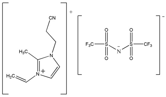
Figure 1.
Sketch of the 1-cyanoethyl-2-methyl-3-allylimidazolium bis (trifluoromethanesulfonimide) salt CEMAImTFSI used in this work.
2. Experimental
2.1. Orbital Energy Calculations
Theoretical calculations were performed using Gaussian 09. The calculation method uses the B3LYP method in the density functional theory (DFT) and the basis set is the 6-311+G(d, p) basis group [42,43]. The Li+ binding affinity (Eb) is calculated by the conductor-variant polarized continuum model (CPCM) method [44], the base set is 6-311+G(d, p), and the dielectric constant of the solution is 46.4 [45].
2.2. CEMAImTFSI and Electrolyte Preparation
The structure of CEMAImTFSI was analyzed with VECTOR22 Fourier transform infrared spectrometer with scanning range of 4500–350 cm−1. The base electrolyte of 1.0 mol/L LiPF6-EC/DMC (ethylene carbonate/dimethyl carbonate) (EC/DMC 1:1 in vol%) was used as reference and recorded as L0. The other electrolytes were prepared by adding various amounts of CEMAImTFSI (5, 10, 15, and 20 vol%,) to the base electrolyte. These electrolytes were labelled as L5, L10, L15, L20.
2.3. Cell Assembly
The 2032-type coin cells were assembled using a prepared LiNi0.5Mn1.5O4 cathode of 16 mm diameter. A Cellgard 2400-type separator of 18 mm diameter was placed between electrodes. Before assembly, the cathode and separator were dried for 12 h in a vacuum oven at 60 °C. The preparation process is completed in a dry glove box filled with high purity argon (99.999%).
2.4. Electrochemical Test
The conductivity of the electrolyte was tested with a conductivity meter (DDSJ-318) at 25 °C. The viscosity of the electrolyte was measured by rotary viscometer (brookfield DV-2 pro). The charge and discharge cycle of the electrolyte was tested using a CT2001A LAND electric charge and discharge test system. The test voltage range was from 3 to 5 V. The electrochemical impedance spectroscopy (EIS) of the electrolyte was measured with a CHI600D type electrochemical workstation, with the frequency range from 0.01 to 105 HZ and an amplitude of 5 mV. The cyclic voltammetry (CV) of the LiNi0.5Mn1.5O4/Li cell was measured with a CHI600D type electrochemical workstation with the scan voltage ranging from 3.5 to 5 V and the scan rate of 0.05 mV·s−1.
2.5. Electrodes Characterization
After the electrochemical test, the cells were disassembled in the glove box. The electrodes were rinsed with DMC, then dried in a vacuum for a day before surface analysis. The surface morphologies of the LiNi0.5Mn1.5O4 cathode were measured in a scanning electron microscope (Nano SEM45). The surface chemical composition of the LiNi0.5Mn1.5O4 cathode was investigated by X-ray photoelectron spectroscopy (XPS, ESCALAB 250Xi).
3. Results and Discussion
3.1. Calculation of the HOMO and LUMO Energy Values and the Li+ Binding Energy Values of CEMAImTFSI
Generally, whether an additive is suitable for cells can be predicted by comparing highest occupied molecular orbital (HOMO) and lowest unoccupied molecular orbital (LUMO) energy values between the functional additives and the electrolyte solvent. The HOMO energy and LUMO energy can predict the redox tendency of the molecule. For example, compared to the electrolyte solvent, a functional additive should have lower LUMO and higher HOMO to suit the anode compartment and be susceptible to oxidation in the cathode region. The calculated HOMO and LUMO energy values of the electrolyte solvents and CEMAImTFSI are shown in Table 1. Compared to EC and DMC, CEMAImTFSI showed higher HOMO energy value, indicating that CEMAImTFSI is a better electron donor. The highest HOMO energy value enables the CEMAImTFSI to get decomposed by oxidation preferentially. Thus, the oxidative decomposition of the EC and DMC is suppressed, thereby improving the oxidation resistance of the electrolyte. Moreover, CEMAImTFSI shows the lowest LUMO energy value relative to the electrolyte solution comprising the ethylene carbonate (EC) and dimethyl carbonate (DMC), indicating CEMAIMTFSI has strong electron-capturing ability, that is to say, CEMAImTFSI is easier to be reduced and form films preferentially on the anode surface during testing. It can be concluded that CEMAImTFSI has an excellent effect on the anode film formation. CEMAImTFSI has a HOMO energy value similar to that of the commercial electrolyte additive vinylene carbonate (VC).

Table 1.
The energy values of highest occupied molecular orbital (HOMO) and lowest unoccupied molecular orbital (LUMO) (energy/eV).
Through the analysis of the electrostatic potential energy diagram and the charge distribution, the final optimized EC-Li+, DMC-Li+, VC-Li+, CEMAImTFSI-Li+ structures and their corresponding Li+ binding energies in the 1.0 mol/L LiPF6-EC/DM-10%CEMAImTFSI solution are shown in Figure 2.
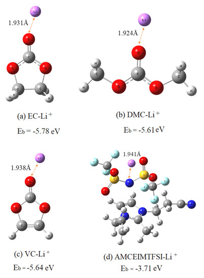
Figure 2.
Li+ binding affinity with organic solvent molecules ethylene carbonate (EC) and dimethyl carbonate (DMC) and additives vinyl carbonate (VC), 1-cyanoehtyl-2-methyl-3-allyl imidazolium bis(trifluromethane sulfonamide) salt and CEMAImTFSI in solution.
CEMAImTFSI-Li+ shows a lower binding energy (−3.71 eV) than EC-Li+ (-5.78 eV), DMC-Li+ (−5.61 eV) and VC-Li+ (−5.64 eV) indicating it is easier to be adsorbed to the surface of the cathode. Therefore, CEMAImTFSI continuously accumulates on the surface of the cathode, forming a layer of SEI film. In summary, CEMAImTFSI has an excellent protection effect on the integrity of the cathode material. CEMAImTFSI is theoretically an effective electrolyte additive.
3.2. Ionic Conductivities and Viscosities of the Electrolyte
The ionic conductivity and viscosity of the electrolyte are the most practical parameters in the characterization of the electrolyte. Both determine the internal resistance and rate characteristics of the battery. The study of the ionic conductivity and viscosities of the electrolyte can provide the design principles of the electrolyte. The Ionic conductivities and viscosities of electrolytes is showen in Figure 3. The ionic conductivity of the electrolyte increases in the range of 0% to 10% additive content, as the ionic liquid is composed of anions and cations; when a small amount of ionic liquid is added to the organic solvents it is completely solvated into free anions and cations and as a result the conductivity of the electrolyte increases. Then it decreases with the increase of CEMAImTFSI content. The reason for the decreasing conductivity is the reduction in charge carrier concentration, induced by the binding between anions and cations forming ion pairs and ion clusters. Furthermore, the increases in viscosity and decrease in fluidity of the electrolyte in the presence of CEMAImTFSI also results in a decrease in the conductivity. Therefore, five groups of electrolytes with high conductivity and low ionic liquid CEMAImTFSI content, L5, L10, L15, L20 and blank electrolyte L0, were selected for performance testing.
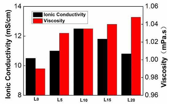
Figure 3.
Ionic conductivities and viscosities of electrolytes.
3.3. Electrochemical Properties of Cells
As shown in Figure 4a, the initial charging curves of these five cells all have an obvious charging platform at around 4.7 V corresponding to the oxidation of Ni2+: Ni2+→Ni4+. The discharge platform at about 4.6 V corresponds to the reduction of Ni4+: Ni4+→Ni2+. A shorter charging platform appears around 4.1 V because there is small amount of Ni3+ in the electrode material and these Ni3+ is oxidized to Ni4+ during charging, that is to say, the corresponding short discharge platform around 4.1 V is the process of Ni4+→Ni3+. In addition, it can be observed that the five LiNi0.5Mn1.5O4/Li cells with different electrolytes (L0, L5, L10, L15 and L20) have the first charge specific capacity of 166.20, 158.68, 152.40, 149.94 and 146.93 mAh·g−1, with corresponding initial discharge specific capacities of 118.59, 122.12, 131.03, 119.95 and 113.12 mAh·g−1, respectively. Accordingly, the coulombic efficiencies were calculated to be 71.35%, 76.96%, 85.95%, 74.66% and 76.99%. When using the L0 electrolyte the capacity retention is low; it was speculated that the structure of the cathode material was damaged, and subsequent experiments proved this conjecture. Moreover, the capacity retention is clearly improved upon the introduction of CEMAImTFSI. It can be concluded from these data that the overcharge phenomenon of the LiNi0.5Mn1.5O4/Li battery is more significant when using L0 electrolyte. The charging specific capacity exceeds the theoretical specific capacity of the LiNi0.5Mn1.5O4 cathode by 13.29%, indicating that a large amount of irreversible Li+ is consumed in the first charge. When CEMAImTFSI is added to the electrolyte, the overcharge phenomenon can be effectively suppressed and the overcharge phenomenon gradually decreases as the CEMAImTFSI content increases. As a result, the coulomb efficiency increases accordingly. In particular, the additive containing 10 vol% CEMAImTFSI showed approximately 14.6% higher retention than the no-additive case. This clearly showed that the CEMAImTFSI suppressed the overcharge phenomenon and increased the capacity retention, illustrating the effect of the CEAMImTFSI.
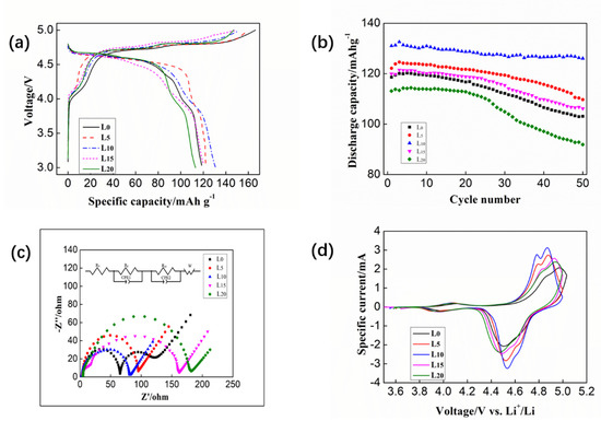
Figure 4.
(a) Initial charge–discharge curves of cells using different electrolytes at 0.2 C. (b) Cycle performance of cells with different electrolytes at 0.2 C. (c) Nyquist plot of cells after 50 cycles with different electrolytes at 0.2 C. (d) Cyclic voltammograms of cells after 50 cycles with different electrolytes.
To investigate the effects of CEAMImTFSI on cycling, the cycle performance of the cell using a cut-off potential of 4.5 V was studied at 25 °C, as shown in Figure 4b. The charge–discharge rate is 0.2 C. It was found that the specific discharge capacity of the cell was only 118.07 mAh·g−1 when the L0 electrolyte was used. After 50 cycles it was only 103.06 mAh·g−1 which is much lower than the theoretical specific capacity of the LiNi0.5Mn1.5O4 cathode. The best performance was obtained by the 10 vol% CEMAImTFSI electrolyte, in which the first discharge specific capacity was 131.03 mAh·g−1 and the discharge specific capacity was still 126.06 mAh·g−1 after 50 cycles and the capacity retention was calculated to be 96.2%. These results illustrated conspicuous improvements in the cycle performance at high cut-off voltage conditions, as the CEMAImTFSI participates in forming a stable cathode-electrolyte interface (CEI) to protect the anode surface, as verified in subsequent XPS experiments. However, the cycle performance of the cell begins to decline as the CEMAImTFSI content continues to increase. When the content of the CEMAImTFSI reached 15 vol%, the discharge specific capacity was almost same as it was when the L0 electrolyte was used. This is due to the larger viscosity of the ionic liquid, which significantly increases the viscosity of the electrolyte and reduces the conductivity. It can be observed that when 10 vol% CEMAImTFSI is added, the cycle performance and capacity retention of the cell are improved. The results clearly show that the oxidative decomposition of the organic solvent EC and DMC is suppressed during the charging and discharging process, thus improve the cycle performance of the cell.
The Nyquist plots after 50 charge–discharge cycles were shown in Figure 4c. The circuit diagram in the figure is the equivalent circuit diagram during the data fitting process. The Nyquist plots show two semi-circles. In the ultrahigh frequency region, where the impedance curve intersects the horizontal axis representing the impedance of the cell (Rs). The first semi-circles at the high frequency represent the impedance of lithium ions through the electrolyte (Rf); the second semi-circles at the intermediate frequency represent the charge transfer impedance—also known as electrode polarization impedance Rct; the low frequency area is controlled by mass transfer, thus, there is a straight line with a slope close to 1 in the low frequency, which represents the lithium ion diffusion impedance, also called Warburg impedance. The EIS fitting data of LiNi0.5Mn1.5O4/Li cell after 50 cycles in different electrolytes are shown in Table 2.
Table 2.
Fitted results of electrochemical impedance spectroscopy (EIS) test for cells R/Ω.
As expected, it can be seen from the data in Table 2 that the Rs resistance value is mainly related to the viscosity and conductivity of the electrolyte, the impedance values after 50 cycles were much smaller for the cells with the CEMAImTFSI additives than those without the CEMAImTFSI cell. Especially, the Rf and Rct of the reference cell were significantly higher than the cell using L5 and L10 electrolyte, indicating that the electrolyte gradually decomposed during the cycle and the formed SEI film gradually thickened and weakened the transmission speed of Li+ between interfaces. When the CEMAImTFSI additive is added, a uniform SEI film is formed on the surface of the cathode. The CEMAImTFSI surface layer prevents the continuous decomposition of the electrolyte, which also increases the transmission speed of Li+. So, the Rf and Rct values of the L5 and L10 electrolyte cells are relatively low. Thus, the performance of the high voltage of the cell is improved due to the incorporation of CEMAImTFSI. This indicates that CEMAImTFSI is an excellent high-voltage additive.
The cyclic voltammetry curve after 50 cycles of the cells with and without CEMAImTFSI additives is shown in Figure 4d. There are two pairs of redox peaks on each curve. The oxidation peak corresponds to the release of Li+ from the positive electrode material, that is, the charging process. The reduction peak corresponds to the insertion of Li+, which is the discharge process. The forward scanning process is a charging process, in which Mn3+→Mn4+ oxidation peak is near 4.0 V. The corresponding reverse scanning process is a discharge process and near 3.9 V in this process is Mn4+→Mn3+ reduction peak. Similarly, during charging process, near 4.9 V is the Ni2+→Ni4+ oxidation peak [43], and the corresponding discharge process near 4.5 V is the Ni4+→Ni2+ reduction peak. Furthermore, the difference (Δφ) between the oxidation peak potential (φa) and the reduction peak potential (φb) in the vicinity of the high voltage reflects the reversibility of the battery. Generally, the larger value of Δφ means the worse reversibility of the battery. Large polarization will hinder the diffusion of lithium and reduce the capacity of the battery, so the polarization should be reduced. CV test results indicated that CEMAImTFSI reduced the polarization and stabilized the cathode surface. Moreover, the shorter the service life of the cell indicates the greater degree of polarization of the battery during the charge–discharge process. By analyzing the CV curve, the oxidation-reduction potential difference of each cell was calculated. The values of the redox potential near the high voltage in the cyclic voltampere curve of cell and the corresponding potential difference values are shown in Table 3. It can be seen from the results that the potential difference of the cell using L10 electrolyte is the smallest, indicating that the polarization degree is low, and the reversibility and electrochemical performance is excellent.
Table 3.
Redox potential of LiNi0.5Mn1.5O4/Li cells φ/V.
3.4. LiNi0.5Mn1.5O4/Li Cell Rate Performance Test
The charge–discharge rate of the cell is an important indicator of the cell during use, and it is urgent to improve the rate performance of the cell, so we need to test the rate performance of the battery under high current.In Figure 5a, it can be seen that when using the L0 electrolyte the capacity attenuates severely at a high rate, and the discharge specific capacity is only 48.78 mAh·g−1 after 10 cycles at the 5 C rate. The cyclic tests indicate that L0 has a poor cycling performance at a high rate. From Figure 5b–d it can be found that the cycle performance of the cells was improved, in particular, when 10 vol% CEMAImTFSI is added; the cycle performance of the cell at different rates is optimal, and the average discharge specific capacity at 5 C is 109.30 mAh·g−1. After being charged and discharged at a high rate, then cycled at a low rate, the capacity of the cell can be restored to the level of the 0.2 C cycle. From this, it can be inferred that the stable CEI formed by CEMAImTFSI protects the integrity of the cathode material. The CEI film inhibits the oxidative decomposition of the electrolyte, and accelerates the transfer of Li+ at the electrode–electrolyte interface. In summary, additive CEMAImTFSI can improve the cycle performance of the cell at high rate.

Figure 5.
(a) Rate performance of cell with L0 electrolyte; (b) rate performance of cell with L5 electrolyte; (c) rate performance of cell with L10 electrolyte; (d) rate performance of cell with L15 electrolyte.
4. Surface Analysis of Electrode with Additives
4.1. Scanning Electron Microscopy Analysis of LiNi0.5Mn1.5O4
To study the influence of CEMAImTFSI on the structural integrity of the LiNi0.5Mn1.5O4 cathode, the cells were disassembled after cycles and observed by scanning electron microscopy (SEM). The SEM images are shown in Figure 6.
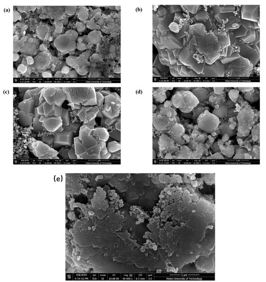
Figure 6.
The SEM images of LiNi0.5Mn1.5O4 cathode with (a) L0 electrolytes; (b) L5 electrolytes; (c) L10 electrolytes; (d) L15 electrolytes; (e) LiNi0.5Mn1.5O4 cathode before cycling.
As illustrated in Figure 6a, the structure of the LiNi0.5Mn1.5O4 cathode is seriously damaged and the crystal size is random indicating that the organic solvent EC and DMC in the electrolyte are oxidatively decomposed on the electrode surface during the cycle of the cell. The LiNi0.5Mn1.5O4 cathode was severely corroded and it destroyed the structure of the electrode material. When a small amount of CEMAImTFSI is added, the well-structured and uniform-sized crystals of the LiNi0.5Mn1.5O4 cathode material can be observed (Figure 6b). The CEMAImTFSI inhibited the decomposition of EC and DMC and the structural integrity of the electrode was protected. The structure of the LiNi0.5Mn1.5O4 cathode material in Figure 6c is more uniform and complete than the structure in Figure 6b, in which the supported cell has optimal cycle performance in a 1.0 mol/L LiPF6-EC/DMC/10 vol% CEMAImTFSI electrolyte. From Figure 6d, it can be observed that when the content of the CEMAImTFSI is too high, the corrosion of the material structure is severe. Moreover, it can be seen that the addition of CEMAImTFSI inhibits the decomposition of EC and DMC and the structural integrity of the electrode material was protected, thereby improving the cycle performance.
4.2. X-Ray Photoelectron Spectroscopy Analysis of LiNi0.5Mn1.5O4 Cathode
To further study the composition of the LiNi0.5Mn1.5O4 cathode, the surface composition of the LiNi0.5Mn1.5O4 cathodes with CEMAImTFSI additive (L10) after 50 charge–discharge cycles were compared with those of the cycled electrodes without additives (L0) by X-ray photoelectron spectroscopic (XPS) investigation.
In the C 1s spectrum of the L0 electrolyte (Figure 7a), the peak at 290.1 eV represents the C–F bond and 284.6 eV assigned to the C–C bond arising from polyvinylidene fluoride (PVDF), which was a binder. Further, peaks at 285.6 and 288.5 eV represented C-O and C=O bonds, which are generated after decomposition of an organic solvent in the electrolyte. After 10 vol% of CEMAImTFSI was added, it was found that the C-O and C=O peaks disappeared indicating that the decomposition of EC and DMC can be effectively inhibited by adding the 10 vol% CEMAImTFSI. In addition, there are new peaks at 292.6 eV and 286.6 eV, indicating that CEMAImTFSI has decomposed on the LiNi0.5Mn1.5O4 cathode. In the O 1s spectrum (Figure 7b), the peaks at 533.2, 531.7, and 529.8 eV represented the C-O, C=O, and metal-O (M-O) bonds. The change of C=O peaks is consistent with the change in the C1s spectrum, which confirms that CEMAImTFSI can inhibit the decomposition of EC and DMC. In the N 1s spectrum (Figure 7c), When 10 vol% CEMAImTFSI is added, it decomposes on the surface of LiNi0.5Mn1.5O4 cathode during the cycle of LiNi0.5Mn1.5O4/Li cell, producing an N-C (398.7 eV) peak and an N-S (401.2 eV) peak. In the F 1s spectrum (Figure 7d), there are two distinct peaks of L0 electrolyte, the PVDF peak at 687.3 eV and the LiF peak at 684.7 eV. The LiF peak (684.7 eV) originates from the reaction of HF and Li+ produced by hydrolysis of LiPF6 salt, which easily precipitates on the surface of the LiNi0.5Mn1.5O4 cathode to form a resistive layer, which inhibits charge transport. It can be found that the intensity of the LiF peak on the LiNi0.5Mn1.5O4 cathode using L0 electrolyte is significantly stronger than using L10 electrolyte, indicating that the LiNi0.5Mn1.5O4 cathode is covered by the decomposition product of CEMAImTFSI during the cycle of the cell after adding 10 vol% of CEMAImTFSI and avoiding the direct contact of the LiF and LiNi0.5Mn1.5O4 cathode. The XPS results are consistent with the Gaussian calculations. As observed, the CEMAImTFSI takes precedence over the EC and DMC decomposition and inhibits the decomposition of EC and DMC, thereby protecting the structural integrity of the LiNi0.5Mn1.5O4 cathode material.
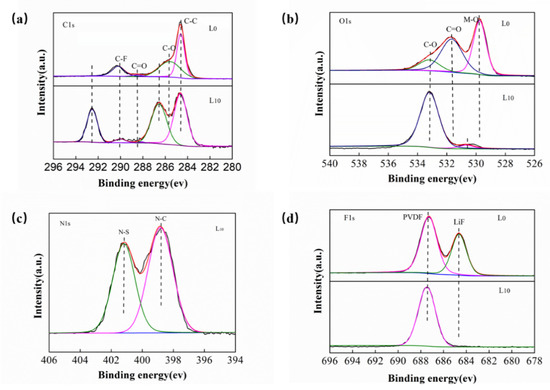
Figure 7.
XPS spectra of the LiNi0.5Mn1.5O4 cathode using L0 and L10 electrolytes after cycling studies (a) C 1s, (b) O 1s, (c) N 1s and (d) F 1s.
5. Conclusions
In this work, an ionic liquid CEMAImTFSI was synthesized as an electrolyte additive to improve the oxidation resistance of the electrolyte in high-voltage lithium-ion batteries. Gaussian 09 calculation indicates that CEMAImTFSI has a higher HOMO and a lower LUMO energy value. This indicates CEMAImTFSI can preferentially decompose the EC and DMC, and form stable passivation films on the surface of electrode, thus, the CEMAImTFSI-derived films can significantly inhibit the further decomposition of electrolyte and protect the integrity of the electrolyte, which improved electrochemical performances of the cell. Specifically, the cell using L10 electrolyte has the initial discharge specific capacity of 131.03 mAh·g−1 at 0.2 C, and the discharge specific capacity still shows 126.06 mAh·g−1 after 50 cycles, with a capacity retention as high as 96.2%. Even at the 5 C rate, the average discharge specific capacity was 109.30 mAh·g−1, which was 1.95 times higher than without the CEMAImTFSI addition. The EIS test shows that in the cell using the L10 electrolyte, the impedance of lithium ions through the electrolyte (Rf) and electrode polarization impedance Rct are significantly reduced, and the CV test proves that the reversibility of the cell is also improved. Moreover, SEM and XPS analysis show that the cell using L10 electrolyte has excellent film-forming performance. In summary, CEMAImTFSI is an effective electrolyte additive. We believe this study will play a guidance role in the development of high-voltage lithium-ion battery electrolytes.
Author Contributions
Conceptualization, Writing-Review & Editing, W.Z.; Methodology, Software, Validation, Formal Analysis, Investigation, Data Curation, Writing-Original Draft Preparation, Y.Z.; Resources, Y.H.; Supervision, Project Administration, Funding Acquisition, Y.H. All authors have read and agreed to the published version of the manuscript.
Funding
This research was funded by Colleges and Universities Technology Research Project (ZD2015118) in Hebei Province Science.
Conflicts of Interest
The authors declare no conflict of interest.
References
- Tarascon, J.M.; Armand, M. Issues and challenges facing rechargeable lithium batteries. Nature 2001, 414, 359–367. [Google Scholar] [CrossRef] [PubMed]
- Aurbach, D.; Zinigrad, E.; Cohen, Y.; Teller, H. A short review of failure mechanisms of lithium metal and lithiated graphite anodes in liquid electrolyte solutions. Solid State Ion. 2002, 148, 405–416. [Google Scholar] [CrossRef]
- Armand, M.; Tarascon, J.-M. Building better batteries. Nature 2008, 451, 652–657. [Google Scholar] [CrossRef]
- Luo, Y.; Lu, T.; Zhang, Y.; Yan, L.; Xie, J.; Mao, S.S. Enhanced electrochemical performance of LiNi0.5Mn1.5O4 cathode using an electrolyte with 3-(1,1,2,2-tetrafluoroethoxy)-1,1,2,2-tetrafluoropropane. J. Power Sources 2016, 323, 134–141. [Google Scholar] [CrossRef]
- Botte, G.G.; White, R.E.; Zhang, Z.J. Thermal stability of LiPF6–EC: EMC electrolyte for lithium ion batteries. J. Power Source 2001, 97, 570–575. [Google Scholar] [CrossRef]
- Zhang, Z.; Hu, L.; Wu, H.; Weng, W.; Koh, M.; Redfern, P.C.; Curtiss, L.A.; Amine, K.J.E.; Science, E. Fluorinated electrolytes for 5 V lithium-ion battery chemistry. Energy Environ. Sci. 2013, 6, 1806–1810. [Google Scholar] [CrossRef]
- Hu, L.; Zhang, Z.; Amine, K.J. Fluorinated electrolytes for Li-ion battery: An FEC-based electrolyte for high voltage LiNi0.5Mn1.5O4/graphite couple. Electrochem. Commun. 2013, 35, 76–79. [Google Scholar] [CrossRef]
- Li, S.; Li, L.; Liu, J.; Jing, J.; Li, X.; Cui, X.J.E.A. Using a lithium difluoro (sulfato) borate additive to improve electrochemical performance of electrolyte based on lithium bis (oxalate) borate for LiNi0.5Mn1.5O4/Li cells. Electrochim. Acta 2015, 155, 321–326. [Google Scholar] [CrossRef]
- Yi, T.-F.; Xie, Y.; Ye, M.-F.; Jiang, L.-J.; Zhu, R.-S.; Zhu, Y.-R.J.I. Recent developments in the doping of LiNi0.5Mn1.5O4 cathode material for 5 V lithium-ion batteries. Ionics 2011, 17, 383–389. [Google Scholar] [CrossRef]
- Kim, H.-J.; Jin, B.-S.; Doh, C.-H.; Bae, D.-S.; Kim, H.-S.J. Improved electrochemical performance of doped-LiNi0.5Mn1.5O4 cathode material for lithium-ion batteries. Electron. Mater. Lett. 2013, 9, 851–854. [Google Scholar] [CrossRef]
- Wei, W.; Heng, L.; Yan, W.; Chao, G.; Zhang, J.J. Effects of chromium doping on performance of LiNi0.5Mn1.5O4 cathode material. Trans. Nonferrous Met. Soc. China 2013, 23, 2066–2070. [Google Scholar]
- Li, J.C.; Ma, C.; Chi, M.F.; Liang, C.D.; Dudney, N.J. Solid Electrolyte: The Key for High-Voltage Lithium Batteries. Adv. Energy Mater. 2015, 5, 6. [Google Scholar] [CrossRef]
- Zheng, X.; Liao, Y.; Zhang, Z.; Zhu, J.; Ren, F.; He, H.; Xiang, Y.; Zheng, Y.; Yang, Y. Exploring high-voltage fluorinated carbonate electrolytes for LiNi0.5Mn1.5O4 cathode in Li-ion batteries. J. Energy Chem. 2020, 42, 62–70. [Google Scholar] [CrossRef]
- Abe, K.; Ushigoe, Y.; Yoshitake, H.; Yoshio, M.J. Functional electrolytes: Novel type additives for cathode materials, providing high cycleability performance. J. Power Sources 2006, 153, 328–335. [Google Scholar] [CrossRef]
- Lee, H.; Han, T.; Cho, K.Y.; Ryou, M.-H.; Lee, Y.M. Dopamine as a novel electrolyte additive for high-voltage lithium-ion batteries. ACS Appl. Mater. Interfaces 2016, 8, 21366–21372. [Google Scholar] [CrossRef] [PubMed]
- Wang, C.; Yu, L.; Fan, W.; Liu, J.; Ouyang, L.; Yang, L.; Zhu, M. 3, 3′-(Ethylenedioxy) dipropiononitrile as an electrolyte additive for 4.5 V LiNi1/3Co1/3Mn1/3O2/graphite cells. ACS Appl. Mater. Interfaces 2017, 9, 9630–9639. [Google Scholar] [CrossRef]
- Rong, H.; Xu, M.; Zhu, Y.; Xie, B.; Lin, H.; Liao, Y.; Xing, L.; Li, W.J. A novel imidazole-based electrolyte additive for improved electrochemical performance of high voltage nickel-rich cathode coupled with graphite anode lithium ion battery. J. Power Sources 2016, 332, 312–321. [Google Scholar] [CrossRef]
- Haregewoin, A.M.; Wotango, A.S.; Hwang, B.J. Electrolyte additives for lithium ion battery electrodes: Progress and perspectives. Energy Environ. Sci. 2016, 9, 1955–1988. [Google Scholar] [CrossRef]
- Park, E.J.; Kwon, Y.-G.; Yoon, S.; Cho, K.Y. Synergistic high-voltage lithium ion battery performance by dual anode and cathode stabilizer additives. J. Power Sources 2019, 441. [Google Scholar] [CrossRef]
- Han, S.Y.; Zhang, H.; Fan, C.J.; Fan, W.Z.; Yu, L. 1,4-Dicyanobutane as a film-forming additive for high-voltage in lithium-ion batteries. Solid State Ion. 2019, 337, 63–69. [Google Scholar] [CrossRef]
- Swiderska-Mocek, A.; Lewandowski, A.; Kurc, B.J.J. Properties of LiNiO2 cathode and graphite anode in N-methyl-N-propylpyrrolidinium bis (trifluoromethanesulfonyl) imide. J. Solid State Electrochem. 2012, 16, 673–679. [Google Scholar] [CrossRef]
- Rangasamy, V.S.; Thayumanasundaram, S.; Locquet, J.P. Ionic liquid electrolytes based on sulfonium cation for lithium rechargeable batteries. Electrochim. Acta 2019, 328, 9. [Google Scholar] [CrossRef]
- Qi, H.; Ren, Y.; Guo, S.; Wang, Y.; Li, S.; Hu, Y.; Yan, F. High-voltage Resistant Ionic Liquids for Lithium-ion Batteries. ACS Appl. Mater. Interfaces 2019. [Google Scholar] [CrossRef] [PubMed]
- Ruther, T.; Bhatt, A.I.; Best, A.S.; Harris, K.R.; Hollenkamp, A.F. Electrolytes for Lithium (Sodium) Batteries Based on Ionic Liquids: Highlighting the Key Role Played by the Anion. Batter. Supercaps 2020. [Google Scholar] [CrossRef]
- Karuppasamy, K.; Theerthagiri, J.; Vikraman, D.; Yim, C.-J.; Hussain, S.; Sharma, R.; Maiyalagan, T.; Qin, J.; Kim, H.-S. Ionic Liquid-Based Electrolytes for Energy Storage Devices: A Brief Review on Their Limits and Applications. Polymers 2020, 12, 918. [Google Scholar] [CrossRef] [PubMed]
- Pandian, S.; Hariharan, K.S.; Adiga, S.P.; Kolake, S.M. Evaluation of Electrochemical Stability and Li-ion Interactions in Ether Functionalized Pyrrolidinium and Phospholanium Ionic Liquids. J. Electrochem. Soc. 2020, 167, 8. [Google Scholar] [CrossRef]
- Wu, C.J.; Rath, P.C.; Patra, J.; Bresser, D.; Passerini, S.; Umesh, B.; Dong, Q.F.; Lee, T.C.; Chang, J.K. Composition Modulation of Ionic Liquid Hybrid Electrolyte for 5 V Lithium-Ion Batteries. ACS Appl. Mater. Interfaces 2019, 11, 42049–42056. [Google Scholar] [CrossRef]
- Javadian, S.; Salimi, P.; Gharibi, H.; Fathollahi, A.; Kowsari, E.; Kakemam, J. Effect of imidazolium-based ionic liquid as electrolyte additive on electrochemical performance of 18650 cylindrical Li-ion batteries at room and 60 degrees C temperatures. J. Iran Chem. Soc. 2019, 16, 2123–2134. [Google Scholar] [CrossRef]
- Hosseini-Bab-Anari, E.; Navarro-Suarez, A.M.; Moth-Poulsen, K.; Johansson, P. Ionic liquid based battery electrolytes using lithium and sodium pseudo-delocalized pyridinium anion salts. Phys. Chem. Chem. Phys. 2019, 21, 18393–18399. [Google Scholar] [CrossRef]
- Zhang, S.J.; Li, J.H.; Jiang, N.Y.; Li, X.Q.; Pasupath, S.; Fang, Y.X.; Liu, Q.B.; Dang, D. Rational Design of an Ionic Liquid-Based Electrolyte with High Ionic Conductivity Towards Safe Lithium/Lithium-Ion Batteries. Chem.-Asian J. 2019, 14, 2810–2814. [Google Scholar] [CrossRef]
- Yamaguchi, K.; Domi, Y.; Usui, H.; Shimizu, M.; Morishita, S.; Yodoya, S.; Sakata, T.; Sakaguchi, H. Effect of Film-Forming Additive in Ionic Liquid Electrolyte on Electrochemical Performance of Si Negative-Electrode for LIBs. J. Electrochem. Soc. 2019, 166, A268–A276. [Google Scholar] [CrossRef]
- Yim, T.; Kwon, M.S.; Mun, J.; Lee, K.T. Room Temperature Ionic Liquid-based Electrolytes as an Alternative to Carbonate-based Electrolytes. Isr. J. Chem. 2015, 55, 586–598. [Google Scholar] [CrossRef]
- Mun, J.; Yim, T.; Park, K.; Ryu, J.H.; Kim, Y.G.; Oh, S.M. Surface Film Formation on LiNi0.5Mn1.5O4 Electrode in an Ionic Liquid Solvent at Elevated Temperature. J. Electrochem. Soc. 2011, 158, A453–A457. [Google Scholar] [CrossRef]
- Borgel, V.; Markevich, E.; Aurbach, D.; Semrau, G.; Schmidt, M. On the application of ionic liquids for rechargeable Li batteries: High voltage systems. J. Power Sources 2009, 189, 331–336. [Google Scholar] [CrossRef]
- Halls, M.D.; Tasaki, K.J. High-throughput quantum chemistry and virtual screening for lithium ion battery electrolyte additives. J. Power Sources 2010, 195, 1472–1478. [Google Scholar] [CrossRef]
- Tasaki, K. Solvent decompositions and physical properties of decomposition compounds in Li-ion battery electrolytes studied by DFT calculations and molecular dynamics simulations. J. Phys. Chem. B 2005, 109, 2920–2933. [Google Scholar] [CrossRef]
- Rakhi, R.; Suresh, C.H. A DFT study on 1,4-dihydro-1,4-azaborinine annulated linear polyacenes: Absorption spectra, singlet-triplet energy gap, aromaticity, and HOMO-LUMO energy modulation. J. Comput. Chem. 2017, 38, 2232–2240. [Google Scholar] [CrossRef]
- Han, Y.K.; Yoo, J.; Yim, T. Computational screening of phosphite derivatives as high-performance additives in high-voltage Li-ion batteries. RSC Adv. 2017, 7, 20049–20056. [Google Scholar] [CrossRef]
- Li, N.; Ma, G.; Che, H.; Jiang, Z.; Shen, M.; Dong, J.; Chen, H.; Ma, Z. Application of density functional theory in the design of high potential electrolyte. Chem. Ind. Eng. Prog. 2019, 38, 3253–3264. [Google Scholar]
- Chen, J.H.; He, L.M.; Wang, R.L. Connection of DFT Molecular Orbital Eigenvalues with the Observable Oxidation Potentials/Oxidation Energies. J. Phys. Chem. A 2013, 117, 5132–5139. [Google Scholar] [CrossRef]
- Yue, H.Y.; Dong, Z.Y.; Yang, Y.G.; Han, Z.L.; Wang, L.; Zhang, H.S.; Yin, Y.H.; Zhang, X.G.; Zhang, Z.T.; Yang, S.T. Fluorophosphorus derivative forms a beneficial film on both electrodes of high voltage lithium-ion batteries. J. Colloid Interface Sci. 2020, 559, 236–243. [Google Scholar] [CrossRef] [PubMed]
- Xing, L.; Wang, C.; Xu, M.; Li, W.; Cai, Z.J. Theoretical study on reduction mechanism of 1, 3-benzodioxol-2-one for the formation of solid electrolyte interface on anode of lithium ion battery. J. Power Sources 2009, 189, 689–692. [Google Scholar] [CrossRef]
- Wang, Y.; Balbuena, P.B. Associations of Alkyl Carbonates: Intermolecular C−H⊙⊙⊙ O Interactions. J. Phys. Chem. A 2001, 105, 9972–9982. [Google Scholar] [CrossRef]
- Park, M.H.; Lee, Y.S.; Lee, H.; Han, Y.K. Low Li+ binding affinity: An important characteristic for additives to form solid electrolyte interphases in Li-ion batteries. J. Power Sources 2011, 196, 5109–5114. [Google Scholar] [CrossRef]
- Han, Y.-K.; Jung, J.; Yu, S.; Lee, H.J. Understanding the characteristics of high-voltage additives in Li-ion batteries: Solvent effects. J. Power Sources 2009, 187, 581–585. [Google Scholar] [CrossRef]
© 2020 by the authors. Licensee MDPI, Basel, Switzerland. This article is an open access article distributed under the terms and conditions of the Creative Commons Attribution (CC BY) license (http://creativecommons.org/licenses/by/4.0/).