Abstract
Control of a perturbed electric power system comprised of a hydrogen fuel cell (HFC), boost and boost/buck DC–DC power converters, and the ultra-capacitor (UC) is considered within an electric vehicle application. A relative degree approach was applied to control the servomotor speed, which is the main controllable load of the electric car. This control is achieved in the presence of the torque disturbances via directly controlling the armature voltage. The direct voltage control was accomplished by controlling the HFC voltage and the UC current in the presence of the model uncertainties. Controlling the HFC and UC current based on the power balance approach eliminated the non-minimum phase property of the DC–DC boost converter. Conventional first order sliding mode controllers (1-SMC) were employed to control the output voltage of the DC–DC boost power converter and the load current of the UC. The current in HFC and the servomotor speed were controlled by the adaptive-gain second order SMC (2-ASMC). The efficiency and robustness of the HFC/UC-based electric power systems controlled by 1-SMC and 2-ASMC were confirmed on a case study of electric car speed control via computer simulations.
1. Introduction
Hydrogen fuel cell electric vehicles (HFCEV) use hydrogen fuel cells (HFC) to power an electric motor. In order to power the electric motor, HFCEV generates electricity by using oxygen from the air and compressed hydrogen (see Figure 1 [1]).
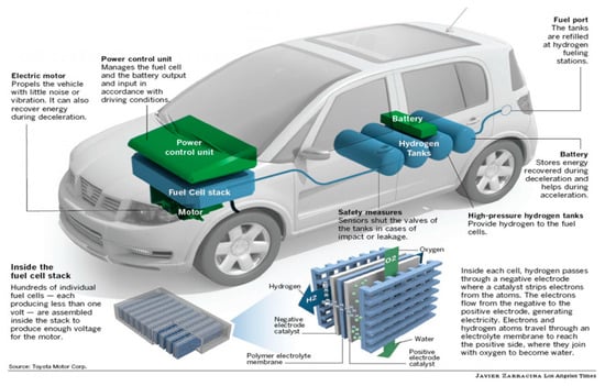
Figure 1.
How a fuel cell car works.
HFCEVs appear to be environmentally friendly, since their by-products are water and heat. A HFCEV study showed that hydrogen vehicles had a higher efficiency when compared to vehicles with traditional gasoline engines [1,2]. In this work, we considered controlling the speed of an electric car in the presence of the torque disturbances and model uncertainties. The task was addressed by controlling the electric power system comprised of HFC conditioned by a DC–DC boost bidirectional power converter, with an ultra-capacitor (UC) as a storage device conditioned by a boost/buck bidirectional converter, in order to drive the speed of the DC electric motor to its time varying command profile.
The necessity of UC employment is based on the fact that HFC cannot generate rapidly changing currents, if required, due to slow HFC membrane dynamics and, therefore, HFC physical constraints [2,3]. It yields a reduced agility of the HFC-based electric car. On the other hand, UC (with a capacitance up to 3500 F) can dump dynamically aggressive current profiles to the load (the electrical motor). The use of UC [2,4] facilitates a fast response to the load current demand. The UC can operate in a wide range of temperature conditions: from +70° Celsius to −40° Celsius, providing high charge acceptance, high-efficiency, cycle stability, and excellent performance. Specifically, HFCEV can deliver enough power to ignition systems, even in cold weather, without relying on traditional batteries [2].
The DC motors (that are considered in this work as a load for the HFC/UC-based electric power system) have some advantages over AC motors as power drives in electric vehicles [3]. Specifically, the DC motors operate with lower voltage, have higher peak torque, and provide faster car acceleration. The high peak torque enables the vehicle to be more adaptable to different driving conditions.
The challenges in controlling the HFC/UC/DC–DC boost and boost/buck converter based electric power system for an electric vehicle application were addressed in this paper as follows:
- The relatively slow uncertain dynamics of the HFC membrane challenge responding to the possible fast load current demand [5,6,7,8,9,10].
- The non-minimum phase property of the DC–DC boost and boost/buck converters challenges a controller design that tracks a causal load voltage profile in the presence of the model perturbations [11,12,13].
- The unknown bounds of the model perturbations challenge the robust controller design [10].
All challenges were addressed in a frame of sliding mode control [10,14,15,16].
The first challenge was addressed by using a controlled UC as a backup source of power supply when there is an interruption of power from HFC or a fast load current demand. Meeting the fast load current demand is addressed by splitting the current command profile into two: “slow” and “fast” profiles. Specifically, a “slow” current command is generated for the HFC, and the “fast” current command profile is generated for UC [17].
The second challenge was answered in this work by controlling the HFC and UC currents based on the power balance condition [4] in the presence of model perturbations. As soon as the non-minimum phase property of the DC–DC boost and boost/buck converters is mitigated by the HFC and UC current control, and the direct tracking of the voltages of the DC–DC boost and boost/buck converters is accomplished by the first order sliding mode control (1-SMC).
The third challenge was addressed by using adaptive second order sliding mode control (2-ASMC) [15,16]. Specifically, adaptive gain super-twisting controller [15,16] was employed for controlling the HFC current through the partial pressure of oxygen. The servomotor speed was robustly controlled by the adaptive-gain twisting controller [4,16].
The rest of this paper is organized as follows. Section 2 illustrates the mathematical modeling of the HFC/UC/DC-DC boost and boost/buck converters based on electric power systems for an electric vehicle application. Section 3 formulates the control problem for a HFC/DC–DC boost converter/UC/DC–DC boost/buck converter-based electric power system. The controller design for the given electric power system is designed in Section 4. The simulations are studied in Section 5 and Section 6 presents the conclusions of the paper.
2. Mathematical Model of Hydrogen Fuel Cell/Ultra Capacitor/Direct Current-Direct Current (HFC/UC/DC-DC) Converter/Servomotor System
The equivalent circuit diagram of an electric power system comprising of HFC/UC/DC-DC boost and boost/buck converters with a servomotor as the system’s load for an electric vehicle is presented in Figure 2, where is the Nernst voltage of HFC; is a HFC current; is the voltage drop across the double layered capacitance due to activation loss; is the resistance that causes the activation loss; is the variable internal resistance of the HFC; is the voltage drop due to ohmic loss; is the output voltage of the DC–DC boost converter; is the voltage across the capacitance ; is the UC current; is the resistance that characterizes the internal losses in UC; is the load (DC servomotor) current; are the armature resistance and inductance of a servomotor respectively; and is the servomotor rotational speed.
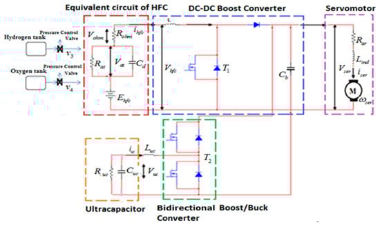
Figure 2.
Equivalent circuit diagram of the Hydrogen Fuel Cell/Ultra Capacitor/Direct Current-Direct Current boost and boost/buck converter-based electric power system for hydrogen fuel cell electric vehicles.
2.1. Mathematical Model of HFC
The typical voltage–current characteristic of HFC [18], which is also called the polarization curve, is presented in Figure 3.
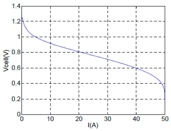
Figure 3.
Typical voltage–current characteristic of HFC.
In this work, it was assumed that HFC operates in a linearity zone depicted in Figure 3. Then, the mathematical model of HFC was derived based on the equivalent circuit in Figure 2, and the dynamics of activation over voltage, Vat, are given as [4,5,6,7,8,9,10]:
The partial pressure of the hydrogen and oxygen dynamics is presented as [19]:
where and are the partial pressures of hydrogen and oxygen, respectively. is the input flow rate (); are the time constants associated with the hydrogen and oxygen flow rates; is the input flow rate (); is the consumed hydrogen flow rate, which is expressed as () with denoting the Faraday constant; and is a number of HFCs in series in the stack.
The actuator valve dynamics are modeled as in [19,20]:
where are the time constants of the oxygen and hydrogen actuator flow-rate valve dynamics, respectively. The inputs of valves and are considered as HFC control functions (i.e., and ).
Remark 1.
The dynamics of the valves in Equations (4) and (5) are considered as unmodeled dynamics and are neglected for the controller design [4]. The valve dynamics were used in the simulations only to validate the designed control.
The output voltage of the stack of HFCs in series, , is defined by equations
where the Gibbs free energy (); and is the standard molar entropy (). The universal gas constant is given as . The Faraday constant is described as . The reference temperature of the HFC is given as and the stack temperature is . The temperature difference is assumed to be the known constant during the process. The variable is dependent on the changes in the concentration of reactants. Due to the insignificant values of and (specifically, ) in Equation (7), the term can be neglected in Equation (6) [4,5,6,7,8,9,10].
2.2. Mathematical Model of the DC–DC Unidirectional Boost Power Converter
The dynamics of the DC–DC boost power converter are governed by the following system of differential equations [4,5,6,7,8,9,10]:
where is a switch control function (a transistor in Figure 2), that is transformed as
and is a symmetric switching control function and is a switch control function (a transistor in Figure 2).
Note that input output () is of relative degree one and the internal dynamics appeared to be unstable, which challenges a tracking input–output controller design [11,12,13].
2.3. Mathematical Model of Ultra Capacitor Controlled by Bidirectional DC–DC Buck (Buck/Boost) Converter
The UC acts as an auxiliary power supply employed in a case of a power interruption from the HFC or a fast load current demand. It is worth noting that the UC:
- (a)
- is more agile than the HFC in following the fast load current command profile.
- (b)
- allows charging and discharging multiple times.
The dynamics of the UC being charged and discharged by a bidirectional DC–DC boost/buck converter were derived as in [4,17]
where ; is a switch control function (transistor in Figure 2); and is a transformed symmetric switching control function.
2.4. Mathematical Model of a Servomotor
The dynamics of a servomotor are given by the following set of equations [7]:
where is the gear ratio; () is a viscous friction coefficient; is the disturbance torque (); and is the system’s moment of inertia ().
2.5. Mathematical Model of HFC/DC-DC Boost Converter/UC/Servomotor
Considering as the electric power system’s outputs and , where transistors and are the switching functions, respectively, and as the control inputs, the input–output dynamics of the system can be derived based on Equations (1)–(13):
where
Remark 2.
Note that control(a symmetric switch control function for transistorin Figure 2), where the derivative is presented in the term, and is designed in a 1-SMC format.
In this case, is defined as
where is the equivalent control, which can be computed by a low pass filtering of the high frequency switching control , and is a differentiable function. This approach is needed only to facilitate the boundedness (at least local) of the term .
The internal dynamics of the HFC system are derived based on Equations (1), (11), and (12):
It is worth noting that the forced zero dynamics in Equation (16) are stable, and the profiles and are bounded, given the forced profile and . Therefore, the input–output dynamics in Equation (14) can be used for the controller design.
Remark 3.
Due to a unique ability of controlling the HFC currentby means ofin Equation (5), the non-minimum phase direct tracking control of the voltagein Equation (8) becomes a minimum phase control problem [12,13].
3. Problem Formulation
The schematic of the HFC/DC-DC/UC/servomotor electric power system for an electric vehicle is presented in Figure 4:
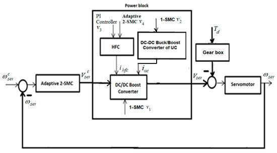
Figure 4.
Schematic of the HFC/DC-DC/UC/servomotor electric power system for an electric vehicle application.
In accordance with the relative degree approach [4,12,14], the input–output error dynamics of vector relative degree were obtained based on the input–output dynamics in Equation (14):
where
The control problem in the HFC/DC-DC/UC/servomotor electric power system is in controlling the rotational speed of the servomotor in the electric vehicle (i.e., achieving as time increases in the presence of the bounded perturbations).
This problem, in accordance with Figure 4, is reduced to the following: design the control functions that drive the tracking errors as time increases in a de-coupled fashion in the presence of the bounded disturbances , where are the command profiles for , respectively, while is assumed to be constant.
The plan of attack on the formulated control problem was inspired by a back-stepping technique [21]:
- Given on line (for instance, it can be a command generated by an electric car driver), design the controller in terms of that drives in the presence of the smooth bounded disturbance torque as in Equations (13) and (15).
- The output of this controller is considered as a command that is to be followed by the HFC/UC/DC-DC boost and boost/buck converters in the inner loop of the electric power system (Figure 4) that generates . The tracking is enforced by the controls .
4. The Controller Design: Relative Degree Approach
4.1. HFC and UC Current Command Generator
The HFC current command profile can be computed based on the power balance [4,17]:
where is the power generated by HFC; is the power consumed by the load (servomechanism); accounts for power losses (for simplicity, the power losses in the converter are neglected, and it is assumed ); is the output current command; and is the command for . The total voltage across stack of HFC’s is . The HFC current command profile is generated as follows:
Note that in implementing Equation (20), can be replaced by the measured .
The HFC current command profile is divided into two “slow” and “fast” commands,
where the “slow” command can be generated as result of the low pass filtering of :
Next, is supposed to follow , while will follow asymptotically the “fast” command profile that is defined based on the already generated and command profiles and a power balance condition as
Equation (12) is valid for and , and can be used for reconstruction (that is used for generation in Equation (20)) given and . This is
where and are Laplace transforms of and , respectively; and here is a Laplace variable. Equation (24) should be understood as follows: the time domain signal is fed to the input of the low pass filter with a transfer function . The output of the filter gives , which can be used in Equation (20).
4.2. Controlling and
The last two equations in the system (Equation (18)) are completely decoupled from the first two equations and have both relative degrees of one:
where Equations (25) and (26) are used for the de-coupled control functions and design.
4.2.1. UC Control: 1-SMC and 2-SMC Approaches
The UC control can be accomplished in two modes:
- (a)
- current control (UC current supply mode),
- (b)
- voltage control (UC charge mode).
The Control Design in Control Mode: 1-SMC Approach
The control —a DC–DC boost/buck converter high frequency switching control—is naturally designed in terms of a conventional SMC to enable the charging/discharging of the ultra-capacitor current (Equation (12)) in the case of a servomotor current demand at a fast rate [4,17]. As the relative degree of is equal to one, the 1-SMC is designed as
where the “fast” command, , for the ultra-capacitor current, , is generated in accordance with Equation (23). As soon as the ultra-capacitor current reaches the command profile in finite time by means of the 1-SMC (Equation (27)) the error becomes , and therefore, in the sliding mode.
Remark 4.
It is assumed that
- is bounded ( i.e.,)
- the control in Equation (27) is sufficiently large to assure the existence of the sliding mode (i.e.,).
Remark 5.
Note that the controlin Equation (27) drives a switching functionthat opens and closes the transistorin Figure 2 with a high frequency in the sliding mode, which can hurt the transistor by overheating. In order to control the switching frequency of the control function, the switching functionin the control law (Equation (27)) can be pulse-width modulated as, whereis a dither signal with a small amplitudeand given frequency. Then, the control law (Equation (27)) implemented aswill drive the original switching functionto a domain. Next,starts switching with the given frequencyin order to maintainin a real sliding mode (i.e., in the domain).
The Controller Design in Control (Charge) Mode: 2-SMC Approach
The UC voltage is decaying with time due to the internal losses and to supplying current to the servomotor. Therefore, should be maintained/charged at a given constant level as soon as it becomes , where is a threshold level. The input–output dynamics is of relative degree 2 in accordance with Equations (10) and (11). The tracking error dynamics of relative degree 2 are derived as
where , .
The high frequency switching 2-SMC is designed in order to drive in finite time in the presence of the perturbation . Specifically, the 2-SMC prescribed convergence law [14] is selected
with selected to provide the desired convergence time [14].
Note that can be obtained using the sliding mode finite-convergent-time differentiator [14] studied in Section 4.3.2.
Remark 6.
It is assumed that
is bounded (i.e.,).
The control in Equation (29) is sufficiently large to assure the existence of the sliding mode, in other words,
Remark 7.
The 2-SMC control law (Equation (29)) can be implemented so that the switching functionthat opens and closes the transistorin Figure 2 is switching with a given frequencyin the real sliding mode, where, andis a dither signal with a small amplitudeand given frequency. Therefore, the 2-SMC control law (Equation (29)) can be implemented as, where. One can see Remark 5 for the details.
4.2.2. The Control v3 Design: PI Control Approach
Since and the term is available ( are measurable), a PI-like continuous controller robustly addresses the set point regulation problem by driving in Equation (26) as time increases:
The parameters ( and ) are tuned in the computer simulation as and . The design and tuning and of the PI controller is well-understood [22], and therefore, omitted for brevity.
4.3. Controlling and : 1-SMC and Adaptive Second Order Sliding Mode Control Approaches
Assume that the sliding mode is established in Equation (25) and the PI-like controller (Equation (30)) drives in Equation (26) as time increases. Then, the first two equations in the system (Equation (17)) can be rewritten replacing by the equivalent control as
Equations (31) and (32) are rewritten in a de-coupled form
where , and can be driven to zero independently by means of .
4.3.1. The Control v1 Design: 1-SMC Approach
The control —a DC–DC converter high frequency switching control—was designed in terms of conventional 1-SMC [4,17], since relative degree of was equal to one. The conventional 1-SMC [4,14] , which represents a switching function, is proposed
Remark 8.
It is assumed that
- is bounded (i.e.,).
- the control v1 in Equation (34) is sufficiently large to assure the existence of the sliding mode (i.e.,).
Then, the control (Equation (34)) drives in finite time , and in the sliding mode.
Remark 9.
The SMC control law (Equation (34)) can be implemented with a given switching frequency. The details of such implementations can be found in Remark 5.
4.3.2. The Control Design: Adaptive Super-Twisting Algorithm
The sliding variable with relative degree 1 is proposed
where is selected to provide a desired eigenvalue placement to the differential equation . Then, the dynamics were derived
where .
The following assumptions were made:
- the gain is known, and
- the derivative of is bounded (i.e., with the unknown boundary ).
The sliding variable in Equation (35) is of relative degree 1. However, the control that drives is required to be continuous. A continuous second order sliding mode control (2-SMC) that is applicable to systems of relative degree 1 and drives , together with its derivative to the real second order sliding mode in finite time, is proposed in terms of adaptive super-twisting control (since the derivative of the perturbation exists, but is not known) with the non-overestimated control gain [16]. Specifically, it is presented as
where the adaptive control gains are defined
where are arbitrary positive constants. Finally, we obtain
The problem of finding real-time robust estimation of is addressed using the sliding mode exact differentiator [14]
where is assumed twice differentiable with the second derivative to be bounded (i.e., ) and the coefficients are to meet the conditions [14]
Then, in finite time. The term replaces in Equation (35). The differentiator in Equations (40) and (41) was tuned for the simulation purposes as .
4.4. Controller Design for Servomotor Speed : Adaptive Twisting Algorithm
In order to drive , we need to design the controller in terms of in accordance with the servomotor dynamics given in Equation (18). Next, is enforced in finite time by the 1-SMC in Equation (34). The continuous controller design is accomplished in the following steps:
Step 1: The sliding variable of relative degree 1 with respect to the control is derived:
where is selected to provide a desired eigenvalue to differential equation . Then, the dynamics are derived
where .
Step 2: The relative degree in the system (Equation (43)) is artificially increased up to 2 () by differentiating in Equation (43). The dynamics of the sliding variable in Equation (42) with respect to the control derivative are derived
where
Assumptions:
- the gain is known,
- the term is bounded (i.e., with the unknown boundary ).
Step 3: 2-SMC adaptive twisting control in terms of that drives the sliding variable and its derivative to the real 2-SM in finite time, preserving the continuity of the control , is designed [15] as:
where , and the arbitrary positive constants are given as .
The servomotor speed controller is finally derived in terms of the continuous output voltage command profile as
The term in Equation (45) was obtained using the sliding mode differentiator in Equation (40) with replaced by . The differentiator (Equation (40))was tuned up for the simulation purposes as .
Remark 10.
It is worth noting that adaptive super-twisting control in Equations (37)–(39) is prone to chattering, since the continuous termhas an infinity gain in the origin. On the other hand, the continuity of the adaptive twisting control in Equations (45)–(47) is guaranteed by integrating the high frequency switching term in Equation (47).
Remark 11.
It is known that super-twisting (Equations (37) and (40)) and twisting (Equations (45) and (47)) control algorithms are sensitive to unmodeled dynamics of the actuator in Equations (4) and (5) that can cause self-sustained oscillations of finite frequency and amplitude [23]. The effects of unmodeled dynamics of the actuator in the studied hydrogen fuel cell-based electric power system of an electric car will be investigated analytically in future work. In this paper, the effects of the unmodeled dynamics of the actuator are studied via simulations.
5. Case Study
The electric car angular velocity control system (Figure 4) was considered. Its electrical energy supply unit consisted of the DC–DC boost converter, the ultracapacitor, and the stack of HFCs. The parameter varies according to the number of HFC in the stack, n. The perturbed electric car angular velocity dynamics are given by Equations (14) and (15). The parameters of the HFC-based electric power system mathematical model may also be uncertain.
5.1. Simulation Set Up
The following DC servomotor speed command profile was given
and the motor disturbance was used as
A simplified version of the Lyapunov function employed in Equation (46)
was used in the simulations as
The parameters of the system (Equations (14), (17), and (18)) are summarized in Table 1.

Table 1.
The parameters of the systems (14), (17), and (18).
The parameters of the controllers in Equation (34) that controls ; in Equation (29) that controls ; in Equation (28) that controls ; in Equations (35)–(39) that controls ; and in Equations (42)–(47) that controls are presented in Table 2.
Table 2.
The parameters of the controllers , , , , and
The system was simulated using the Euler method with a fixed step of .
5.2. Simulation Results
The high accuracy casual tracking of the servomotor speed profile in the presence of perturbations is shown in Figure 5. The accurate causal tracking of the output voltage of the DC–DC boost converter is illustrated in Figure 6. The HFC’s current tracking via adaptive super-twisting control was in Equations (37)–(39), as shown in Figure 7. The corresponding adaptive gain of the adaptive super-twisting controller, shown in Figure 8, demonstrates the significant adaptation depth and the gain non-overestimation. It was observed that for , the adaptive gain and in accordance with Equation (38). The ultra-capacitor current and its command profile are depicted in Figure 9. High accuracy tracking was observed. It can be seen that the UC current rapidly changed (Figure 9) in transient-times compared to the HFC current (Figure 7), which is beneficial for the life-duration of the FC. The HFC current continuous control function is presented in Figure 10. The stabilization of the partial pressure of hydrogen at the constant level via the PI controller in Equation (30) is shown in Figure 11. The time-varying gain of the twisting adaptive controller is shown in Figure 12. A significant adaptation depth and the gain non-overestimation were observed. The plots of the sliding variables and their derivatives (i.e., and ) are presented in Figure 13 and Figure 14, respectively. Glitches observed in Figure 13 correspond to the plot in Figure 12 that correspond to the time instants when the adaptive gain dropped below the level . Then, gain started increasing again in accordance with Equations (45) and (46). Figure 12 and Figure 13 illustrate how the gain non-overestimation is achieved in adaptive twisting control. The plots of the sliding variable and its derivative that are shown in Figure 14 confirm the existence of the sliding mode.
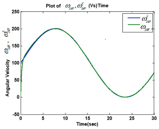
Figure 5.
Plots of the servomotor speed command profile and speed .
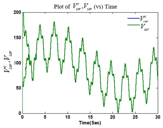
Figure 6.
The DC–DC boost converter voltage command profile and voltage .
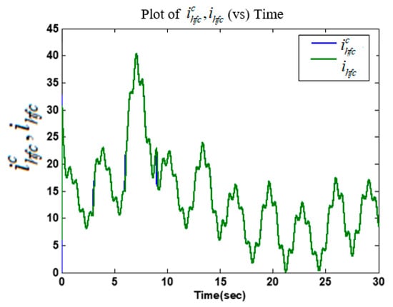
Figure 7.
Time history of HFC command profile and HFC current .
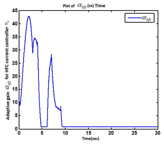
Figure 8.
Time history of the adaptive gain .
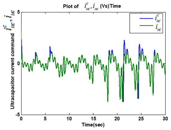
Figure 9.
Time history of UC current command profile and current .
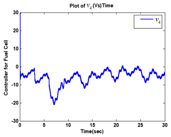
Figure 10.
Plot of HFC current controller .
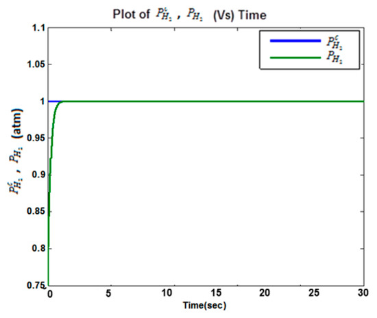
Figure 11.
Plots of the partial pressure of hydrogen command profile and hydrogen partial pressure .
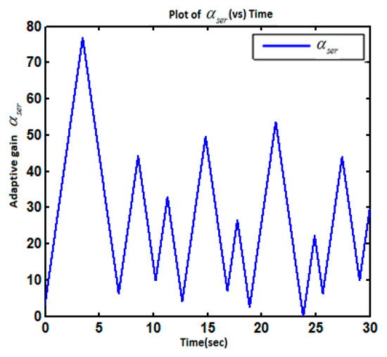
Figure 12.
Plot of the adaptive gain .
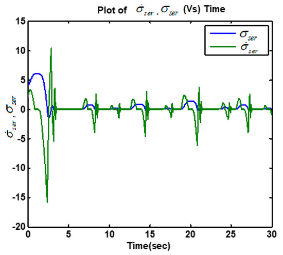
Figure 13.
Plot of the servomotor sliding variable .
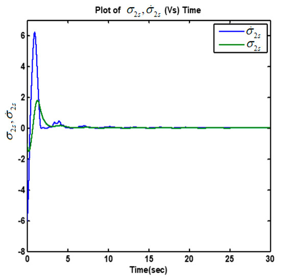
Figure 14.
Plot of the fuel cell sliding variable and its derivative .
6. Conclusions
Control of the speed of an electric vehicle was considered within the perturbed electric power system comprised of a hydrogen fuel cell (HFC), boost and boost/buck DC–DC power converters, and the ultracapacitor (UC). A relative degree approach in a concert with sliding mode control and observation techniques including first order SMC and second order adaptive super-twisting and twisting algorithms was applied for controlling the servomotor speed via the direct control of the input armature voltage. The direct voltage control was accomplished by controlling the HFC current, and the UC current in the presence of the model uncertainties. Controlling the HFC and UC current based on the power balance approach eliminated the non-minimum phase property of the DC–DC boost converter. The current in HFC and the servomotor speed (in the presence of torque disturbance) were controlled by the adaptive-gain second order sliding mode controllers (2-ASMC). Conventional sliding mode controllers (1-SMC) were employed for controlling the output voltage of the DC–DC boost power converter and the load current of the UC. The efficacy and robustness of the HFC/UC-based electric power systems controlled by 1-SMC and 2-ASMC were confirmed on a case study of electric car speed control via computer simulations. Note that the proposed sliding mode control approach to speed the control of an electric car powered by the HFC-based electric power system is applicable to the control of any electric car and guarantees the effectiveness and robustness to the bounded perturbations.
Author Contributions
Y.B.S. proposed the sliding mode control solution of nonminimum phase system consisting of a Hydrogen Fuel Cell (HFC), boost and boost/buck DC-DC power converters and the Ultracapacitor (UC). M.G. contributed to the application of the proposed sliding mode control approach in electric vehicle R.S.A. concentrated her efforts on the implementation of the proposed sliding mode control approach and simulations. All authors have read and agreed to the published version of the manuscript.
Funding
This research received no external funding.
Conflicts of Interest
The authors declare no conflicts of interest.
Abbreviations
| HFC | Hydrogen fuel cell |
| UC | Ultra-capacitor |
| 1-SMC | The conventional first order sliding mode controllers |
| 2-ASMC | Adaptive-gain second order SMC |
| HFCEV | Hydrogen fuel cell electric vehicles |
References
- Fueling the Future Hydrogen Fuel Cell Vehicles in the 21st Century. Available online: http://serc.berkeley.edu/fueling-the-future-hydrogen-fuel-cell-vehicles-in-the-21st-century/ (accessed on 20 October 2015).
- Five Reasons Why Ultracapacitors Are Attractive to Auto Manufacturers. Available online: http://www.environmentalleader.com/2012/01/10/five-reasons-why-ultracapacitors-are-attractive-to-auto-manufacturers/ (accessed on 12 January 2010).
- Dc Motors Deliver High Performance and Efficiency for Electric Motorcycles. Available online: http://www.engineerlive.com/content/21329 (accessed on 21 February 2013).
- Ashok, R.; Shtessel, Y. Control of fuel cell-based electric power system using adaptive sliding mode control and observation techniques. J. Frankl. Inst. 2015, 352, 4911–4934. [Google Scholar] [CrossRef]
- Hilairet, M.; Ghanes, M.; Bethoux, O.; Tanasa, V.; Barbot, J.-P.; Normand-Cyrot, D. A passivity-based controller for coordination of converters in a fuel cell system. Control. Eng. Pr. 2013, 21, 1097–1109. [Google Scholar] [CrossRef]
- Ghanes, M.; Hilairet, M.; Barbot, J.-P.; Bethoux, O. Singular Perturbation Control for Coordination of Converters in a Fuel Cell System; ELECTRIMACS: Cergy-Pontoise, France, 2011; pp. 1–8. [Google Scholar]
- Ashok, R.S.; Shtessel, Y.B. Control of a fuel cell vehicle using adaptive sliding mode control: Servomotor application. In Proceedings of the American Control Conference, Boston, MA, USA, 6–8 July 2016; pp. 2235–2240. [Google Scholar]
- Correa, J.; Farret, F.A.; Canha, L.N.; Simões, M.G. An Electrochemical-Based Fuel-Cell Model Suitable for Electrical Engineering Automation Approach. IEEE Trans. Ind. Electron. 2004, 51, 1103–1112. [Google Scholar] [CrossRef]
- Khan, M.J.; Iqbal, M.T. Dynamic Modelling and Simulation of a Fuel Cell Generator. Fuel Cells 2005, 5, 97–104. [Google Scholar] [CrossRef]
- Kunusch, C.; Puleston, P.F.; Mayosky, M.A.; Riera, J. Sliding Mode Strategy for PEM FCs Stacks Breathing Control Using a Super-Twisting Algorithm. IEEE Trans. Control Syst. Technol. 2009, 17, 167–174. [Google Scholar] [CrossRef]
- Olm, J.M.; Oton, X.R.; Shtessel, Y. Stable inversion-based robust tracking control in DC-DC nonminimum phase switched converters. Automatica 2011, 47, 221–226. [Google Scholar] [CrossRef]
- Isidori, A. Nonlinear Control Systems, 3rd ed.; Springer: London, UK, 1995. [Google Scholar]
- Shtessel, Y.B.; Zinober, A.S.I.; Shkolnikov, C. Sliding mode control of boost and buck-boost power converters using method of stable system centre. Automatica 2003, 39, 1061–1067. [Google Scholar] [CrossRef]
- Shtessel, Y.; Edwards, C.; Fridman, L.; Levant, A. Sliding Mode Control and Observation; Birkhauser: New York, NY, USA, 2014. [Google Scholar]
- Shtessel, Y.B.; Moreno, J.A.; Fridman, L. Twisting sliding mode control with adaptation: Lyapunov design, methodology and application. Automatica 2017, 75, 229–235. [Google Scholar] [CrossRef]
- Shtessel, Y.B.; Taleb, M.; Plestan, F. A novel adaptive-gain supertwisting sliding mode controller: Methodology and application. Automatica 2012, 48, 759–769. [Google Scholar] [CrossRef]
- Ashok, R.; Shtessel, Y.; Smith, J. Sliding mode control of electric power system comprised of fuel cells, DC-DC boost converters and ultracapacitors. In Proceedings of the American Control Conference, Washington, DC, USA, 17–19 June 2013; pp. 5766–5771. [Google Scholar]
- Vishnyakov, V. Proton exchange membrane fuel cells. Vacuum 2006, 80, 1053–1065. [Google Scholar] [CrossRef]
- Padullésa, J.; Aultb, G.W.; McDonald, J.R. An integrated SOFC plant dynamic model for power systems simulation. J. Power Sources 2000, 86, 495–500. [Google Scholar] [CrossRef]
- Belmokhtar, K.; Hammoudi, M.H.; Doumbia, M.L.; Agbossou, K. Modelling and Fuel Flow Dynamic Control of Proton Exchange Membrane Fuel Cell. In Proceedings of the 4th International Conference on Power Engineering, Energy and Electrical Drives, Istanbul, Turkey, 13–17 May 2013; pp. 415–420. [Google Scholar]
- Krstic, M.; Kanellakopoulos, I.; Kokotovic, P. Nonlinear and Adaptive Control Design; Wiley: New York, NY, USA, 1995. [Google Scholar]
- Dorf, R.; Bishop, R. Modern Control Systems, 12th ed.; Prentice Hall: Upper Saddle River, NJ, USA, 2010. [Google Scholar]
- Boiko, I.; Fridman, L. Analysis of chattering in continuous sliding mode controllers. IEEE Trans. Autom. Control 2005, 50, 1442–1446. [Google Scholar] [CrossRef]


© 2020 by the authors. Licensee MDPI, Basel, Switzerland. This article is an open access article distributed under the terms and conditions of the Creative Commons Attribution (CC BY) license (http://creativecommons.org/licenses/by/4.0/).