Abstract
This paper presents a compact nonlinear thermal model of pulse transformers. The proposed model takes into account differentiation in values of the temperatures of a ferromagnetic core and each winding. The model is formulated in the form of an electric network realising electrothermal analogy. It consists of current sources representing power dissipated in the core and in each of the windings, capacitors representing thermal capacitances and controlled current sources modelling the influence of dissipated power on the thermal resistances in the proposed model. Both self-heating phenomena in each component of the transformer and mutual thermal couplings between each pair of these components are taken into account. A description of the elaborated model is presented, and the process to estimate the model parameters is proposed. The proposed model was verified experimentally for different transformers. Good agreement between the calculated and measured waveforms of each component temperature of the tested pulse transformers was obtained. Differences between the results of measurements and calculations did not exceed 9% for transformers with a toroidal core and 13% for planar transformers.
1. Introduction
Pulse transformers are an important component of switched-mode power converters [1,2,3]. These transformers have simple structure, and they consist of two kinds of components, i.e., a ferromagnetic core and at least two windings. During the operation of the considered device, an increase in temperature of each transformer component is observed [4,5,6]. This increase is a result of thermal phenomena occurring in the pulse transformer, such as self-heating in each component of the transformer and mutual thermal interaction between each pair of these components [7,8,9].
Knowing the core temperature and the windings temperatures is important from the point of view of electrical and magnetic properties of a pulse transformer. As is shown in [10,11], the temperature significantly changes the characteristics of ferromagnetic materials used to make a transformer core and causes a change in the resistances of the windings. In particular, an excessive increase in temperature can lead to damage in the insulation of the windings or can reduce the magnetic permeability of the core [8,11,12]. Additionally, an increase in the temperatures of electronic components causes a decrease in their lifetime [13,14].
In order to calculate the temperature waveforms of electronic components with thermal phenomena taken into account, a thermal model of these components is indispensable [15,16]. In many papers [10,11,17,18,19,20,21,22,23,24,25], thermal models of transformers are described, but they have disadvantages. One group of thermal models is microscopic models, which make it possible to calculate temperature distribution in the considered component. For example, in [11,18], the finite element method is used to determine the temperature distribution in a transformer, but at the same time the distribution of the wasted power per unit of volume in the transformer is assumed. Another group of thermal models is compact thermal models, which take into account only one temperature characterising the whole device [17].
Reference [26] presents three-dimensional (3-D) numerical compact thermal models of planar transformers. The DC thermal network of the cited model is inspired by the Delphi method, which allows obtaining shorter time of calculations than the finite volume method. The presented results do not illustrate the influence of dissipated power on the temperatures of the core and the windings. Additionally, this model is dedicated to the ANSYS software, and it is difficult to implement it in other software, e.g., in SPICE.
The similar approach to modelling thermal properties of electronic components is presented in [27,28]. The model presented in [27] uses homogenisation techniques to reduce calculation requirements. The advantage of this model is the reduction of the number of thermal factors to 6–8, and good agreement between the results of calculations and measurements can still be obtained. Unfortunately, the mentioned model could be used in the software dedicated only to a 3-D thermal analysis. In turn, the approach to the thermal modelling of components of electric machines presented in [28] requires time-consuming measurements of the tested prototype. In the paper [28], some temperature waveforms of the tested machine are presented.
Reference [29] describes a simplified form of an electrothermal model dedicated to planar magnetic components (inductors and transformers), which operate in the space industry. An important part of this model is the thermal model dedicated to the ANSYS program. Due to the fact that a lot of factors are taken into account, the network representation of the proposed model is complex and contains three subcircuits representing the thermal network of the transformer windings, the thermal network of the transformer core and the thermal network of the connection between the windings and the Printed Circuit Board (PCB).
References [30,31] are dedicated to parameters estimation of thermal models of electronics devices in the Delphi-inspired form. To this end, genetic algorithms are used. Unfortunately, for multiple heat sources in such models, calculations are time-consuming, and the total simulation time can reach 800 h.
Reference [32] presents a thermal model of a planar transformer. The form of this model is obtained on the basis of computation fluid dynamics. The structure of this model is adequate for planar transformers only. Unfortunately, in the paper [32], no results of experimental verification of this model are presented.
Compact thermal models of transformers are described in [10,11,17,18,26]; however, differences between the core and windings temperatures are typically not taken into account in the mentioned models. In addition, in the models described in [24,25], the dependence of the dissipation efficiency of heat generated in the device on the power dissipated in the transformer is omitted [33].
It is widely known [7,15,16,34,35,36] that some factors, such as ambient temperature, cooling systems or power dissipated in electronic devices, influence the efficiency of heat removal from the devices. Reference [37] presents a nonlinear thermal model of a planar transformer. In this model, the influence of power dissipated in particular components of the transformer on the efficiency of heat removal is taken into account.
This paper, which is an extended version of Reference [38], proposes a compact nonlinear thermal model (CNTM) of a pulse transformer based on a thermal model of a planar transformer described in [19]. In comparison to [19], which presents a linear thermal model, the nonlinearity of the heat transfer process is taken into account. In comparison to [38], a detailed description of the nonlinear thermal model of the transformer and the new results of measurements and calculations illustrating the effectiveness of this model for transformers including different ferromagnetic cores are presented in this paper. The model proposed by the authors’ takes into account self-heating phenomena in all components of the transformer and mutual thermal couplings between each pair of these components.
The selected thermal models of transformers given in the literature are discussed in Section 2. The form of a nonlinear thermal model is presented in Section 3. The obtained results of measurements and calculations proving the effectiveness of the elaborated model are shown in Section 4. The advantage of this nonlinear thermal model over a linear thermal model is experimentally confirmed for the selected transformers containing cores with different shapes and made of different ferromagnetic materials. For all models described in the following sections, thermal resistance and thermal capacitance are given in K/W and J/K, respectively, whereas all temperatures are expressed in Celsius degrees.
2. Selected Thermal Models of Transformers in the Literature
A network representation of classical linear thermal models of transformers [10,39] is shown in Figure 1. It can be seen that only one internal temperature of the whole transformer is used. In this model, differences in the temperatures of the core and the windings are not taken into account.
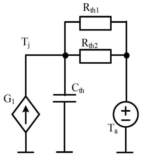
Figure 1.
Network representation of the thermal model described in [10,39].
In the presented model, the controlled current source G1 represents the sum of the power dissipated in the core and in the windings of the transformer. Thermal capacitance is represented by capacitor Cth, while Rth1 is the thermal resistance characterising heat convection and Rth2 is thermal resistance characterising the heat radiation from the surface of the examined device. Voltage source Ta is the ambient temperature, and the voltage in node Tj is the temperature of the transformer.
In [17,33], a thermal model of magnetic components (transformers and inductors) is proposed. This model enables calculating the temperature difference between the core and ambient temperature (ΔTC) and the temperature difference between the windings and ambient temperature (ΔTW) by taking into account self-heating and mutual thermal couplings between the core and the windings. The network representation of this model is shown in Figure 2.
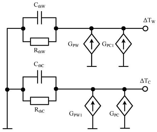
Figure 2.
Network representation of the thermal model of magnetic components from [18].
However, in this model, only single thermal time constants for the windings (RthW and CthW) and for the core (RthC and CthC) are taken into account. Current sources GPC and GPW describe power losses in the core and in the windings, respectively; whereas current sources GPC1 and GPW1 model the influence of mutual thermal couplings between the core and the winding on the temperature differences ΔTW and ΔTC.
The thermal model of a transformer proposed in [17], of which the diagram is presented in Figure 3, makes it possible to calculate the temperature of the core TC and the temperatures of both windings TW by taking into account self-heating and mutual thermal couplings between the core and the windings. This model has the form of RC Foster networks excited by current sources representing the powers dissipated in the core (PthC and PthWC1) and in the windings (PthW and PthWC1).
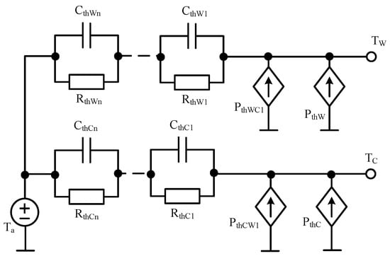
Figure 3.
Network representation of the thermal model of a transformer proposed in [17].
In order to take into account thermal couplings between the core and the windings, controlled current sources PthWC1 and PthCW1 are applied. The voltage source Ta represents ambient temperature. In the described model, common RC networks are used to model self-heating and mutual thermal couplings between the components of the transformer.
A disadvantage of thermal models of transformers described in this section is they do not take into account differentiations of windings temperatures, nonlinearities of thermal properties and thermal couplings occurring between the components of the transformer. Therefore, in the following Section, the authors’ nonlinear thermal model of the transformer is proposed. In this model, nonlinearities of thermal phenomena and thermal couplings between the components of the transformer are taken into account.
3. Proposed Nonlinear Thermal Model of Pulse Transformers
As is shown in [17,19], temperature distributions on each of the windings and on the core in pulse transformers are practically uniform. Therefore, their thermal properties can be described with the use of a compact thermal model [7,19]. On the other hand, the temperatures of the core and the windings can be significantly different from each other [7]. Therefore, in such models, the differences of the core and windings temperatures should be taken into account. In each transformer component, a self-healing phenomenon occurs, and additionally, thermal interaction between each pair of transformer components is observed.
The nonlinear thermal model of the transformer worked out by the authors has the form of a subcircuit dedicated for SPICE. This form is inspired by the linear thermal model of a planar transformer proposed in [19] and by the nonlinear thermal model of semiconductor devices described in [37,40]. In the new model, the differences in the temperatures of components in the transformer (the core and all the windings) are taken into account. These temperatures result from self-heating phenomena in every component and mutual thermal couplings between each pair of the components of the transformer. The presented model makes it possible to calculate the temperature waveforms of the core and each winding by taking into account both the mentioned phenomena. When formulating the considered model, based on the results of measurements shown in [7], changes in the powers dissipated in each component influence only the values of transformer thermal resistances in the thermal model, whereas thermal capacitances do not depend on power. The network representation of the proposed model is presented in Figure 4.
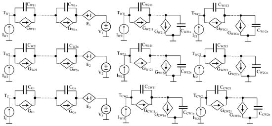
Figure 4.
Network representation of a compact nonlinear thermal model (CNTM) of a pulse transformer.
In this network, nine circuits can be distinguished. Three of them located on the left-hand side of Figure 4 are used to calculate the temperature waveforms of particular components of the transformer—the primary winding TW1, the secondary winding TW2 and the core TC. These temperatures (given in °C) correspond to the voltages (given in V) in the nodes and are denoted as TW1, TW2 and TC, respectively. Current sources IC, IW1 and IW2 model power losses in the core and the two windings, respectively.
Circuits including capacitors and controlled current sources model self-transient thermal impedances of the primary winding (CW11, …, CW1n and GW11, …, GW1n), of the secondary winding (CW21, …, CW2n and GW21, …, GW2n) and of the core (CC1, …, CCn and GC1, …, GCn), respectively. The voltages on these circuits (given in V) correspond to differences (given in °C) between the temperatures of the transformer components and ambient temperature, resulting from self-heating phenomena.
The controlled voltage sources E1, E2 and E3 represent the influence of mutual thermal couplings between the components of the transformer on the temperatures of these components. Capacitors represent the thermal capacitances of all the elements in the heat flow path, whereas the controlled current sources represent nonlinear thermal resistances between the elements in the heat flow path.
The output voltage of the controlled voltage source E1 is equal to the sum of voltages in nodes TW11 and TWC1, the output voltage of the controlled voltage source E2 is equal to the sum of voltages in nodes TW21 and TWC2, and the output voltage of the controlled voltage source E3 is equal to the sum of voltages in nodes TCW1 and TCW2. Voltage sources V1, V2 and V3 represent ambient temperature.
Six other subcircuits are used to model mutual thermal couplings between each pair of the transformer components. Current sources in these subcircuits represent power (given in W) dissipated in particular components of the transformer (IW12 and IW1C in the primary winding, IW21 and IW2C in the secondary winding and IC1 and IC2 in the core). Networks containing capacitors and controlled current sources connected to the above-mentioned current sources model mutual transient thermal impedances between each pair of components of the transformer.
All self-transient and mutual transient thermal impedances can be described by Equation (1) [7,15]:
where Rth is the thermal resistance, ai is the coefficient (without unit) corresponding to thermal time constant τthi (given in s), and N is the number of thermal time constants.
The dependence of Rth on the dissipated power is described as:
where Rth0 denotes the minimum value of the thermal resistance, p denotes the power dissipated in a heating component of the transformer, α is the parameter without unit, and p0 and b are model parameters given in W.
Changes in values of thermal resistance are modelled by the controlled current source Gi. The output current of the controlled source is described as:
where VGi denotes the voltage on the current source Gi.
Thermal capacitances are given as:
The values of the model parameters are estimated using the results of measurements of self- and mutual transient thermal impedances existing in the transformer thermal model. Measurements of such parameters at different powers dissipated in the core and in the windings of the tested transformer are realised by the method described in [7]. The values of parameters in Equation (1) are estimated for each transient thermal impedance using the method described in [15,41]. Next, parameters α, p0 and b in Equation (2) are estimated for self-thermal and mutual thermal resistance in the transformer model by using local estimation [15].
4. Results
In order to verify the presented model and its practical use, measurements and calculations of the temperature waveform of each component of the tested transformers, which contained ferromagnetic cores with different shapes and sizes and were made of different materials, were performed. A planar transformer with a ferrite core and transformers with ring cores made of different materials were measured and modelled as examples.
The planar transformer, of which the cuboidal core dimension was 22 mm × 16 mm × 9 mm, was made of ferrite material 3F3 and contained windings in the form of printed paths on laminate FR-4, which was 1 mm thick. The primary winding contained three turns with a width of 2.5 mm, and the secondary winding contained four turns with a width of 1 mm. Transformers with a toroidal core contained identical primary and secondary windings. On each of them, 20 turns of copper wire in the enamel with a diameter of 0.8 mm were wound. The toroidal core had an external diameter equal to 26 mm, the internal diameter equal to 16 mm and a width equal to 11 mm. Cores made of toroidal powdered iron (RTP), ferrites (RTF) and nanocrystals (RTN) were used for toroidal transformers.
The values of the parameters in the thermal model were estimated for transformers containing ferromagnetic cores with different shapes and dimensions and made of different ferromagnetic materials.
The values of the parameters in Equation (2), which represents the proposed compact nonlinear thermal model of the transformer (CNMT), are summarized in Table 1 (for a toroidal transformer) and Table 2 (for a planar transformer). The values of the parameters presented in Table 1 and Table 2 describe the model of the network representation shown in Figure 4.

Table 1.
Values of the parameters in Equation (2) for a toroidal transformer with a toroidal powdered iron core (RTP).
Table 2.
Values of the parameters in Equation (2) for a planar transformer.
Comparing the values of the parameters describing thermal resistances in the thermal model of the toroidal transformer, it is obvious that the values of parameters α, p0 and b were nearly the same for all considered thermal resistances. Differences were observed in the values of the parameter Rth0. This meant that courses RthW1(pW1), RthW1W2(pW1) and RthW1C(pW1) were nearly parallel. In contrast, big differences were observed between the values of the parameters describing the dependences of thermal resistances in the thermal model of the planar transformer on powers PW1 and PC.
The values of thermal capacitances were estimated with the use of the method described in [15]. As an example, in Table 3, the values of these parameters obtained for a planar transformer are summarised.
Table 3.
Values of the parameters ai and τthi of the selected self-transient and mutual transient thermal impedances in a thermal model of a planar transformer.
It can be clearly seen that, in the considered self-transient and mutual transient thermal impedances, different numbers of thermal time constants occurred. In self-transient thermal impedances, three or four thermal time constants were used, whereas mutual transient thermal impedances were described with two or three thermal time constants. The values of the considered thermal time constants were in a range from 40 μs to over 1000 s.
For example, by means of Equation (2), the measured (indicated by points) and modelled (indicated by lines) dependences of thermal resistances in the thermal model of the transformer on the power dissipated in one of the components of the transformer are shown in Figure 5 and Figure 6.
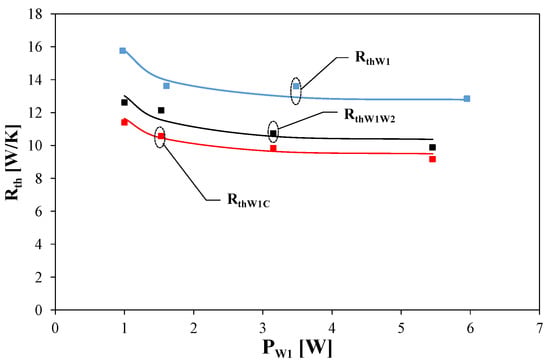
Figure 5.
Measured (indicated by points) and modelled (indicated by lines) dependences of the selected thermal resistances in the thermal model of the transformer with a toroidal core made of powdered iron on the power dissipated in the primary winding.
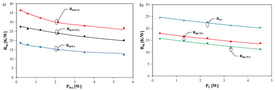
Figure 6.
Measured (indicated by points) and modelled (indicated by lines) dependences of the selected thermal resistances in the thermal model of the planar transformer on the power dissipated in the primary winding (a) and in the core (b).
Figure 5 illustrates the influence of power PW1 dissipated in the primary winding of the transformer containing a toroidal core made of powdered iron on the thermal resistance of the winding RthW1 (blue colour) and on mutual thermal resistances between this winding and the secondary winding RthW1W2 (black colour), as well as those between the core and the primary winding RthW1C (red colour).
Figure 6a illustrates the influence of power dissipated in the primary winding of the planar transformer on the thermal resistances RthW1 (blue colour), RthW1W2 (black colour) and RthW1C (red colour). Figure 6b illustrates the influence of power dissipated in the core of the transformer on the thermal resistance of the core RthC (blue colour) and the mutual thermal resistances between the core and both windings RthCW1 (red colour) and RthCW2 (green colour).
As it is obvious in Figure 5 and Figure 6, it is possible to accurately model the measured dependences of the considered thermal resistance on the dissipated power using Equation (2). Visible differences between self-thermal and mutual thermal resistances were observed for both considered transformers. These thermal resistances differed from one another. It is worth noticing that the considered differences were bigger for the planar transformer than for the toroidal transformer. Changes in dissipated power can cause changes in thermal resistance even by 25%.
Calculations and measurements were performed at power dissipation in only one of the components of the tested transformers and at simultaneous dissipation of power in different components of the tested devices. Power dissipated in each component of the transformer always had a shape of a single rectangular impulse with a long duration time. The results of calculations obtained by means of the nonlinear thermal model were compared to the results of calculations performed by means of the linear thermal model described in [19] and the results of measurements performed with the use of a pyrometer. The windings and the core were excited with different powers. The successive figures (Figure 7, Figure 8, Figure 9, Figure 10, Figure 11 and Figure 12) present the calculated and measured waveforms of the temperatures of the primary winding TW1, the secondary winding TW2 and the core TC of the tested transformers. In these figures, the results of measurements is represented by points, the results of calculations performed using the CNTM is represented by solid lines, and the results of calculations using the compact linear thermal model (CLTM) is represented by dashed lines [19].
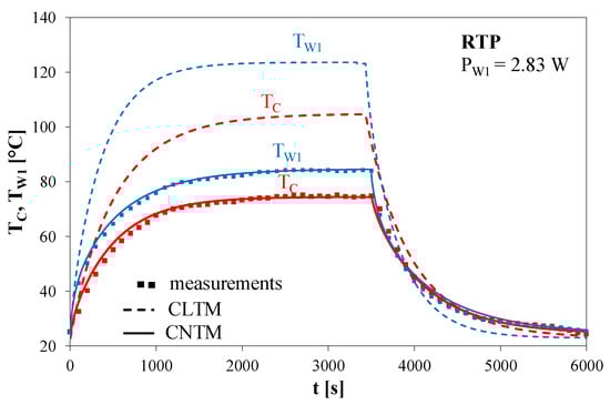
Figure 7.
Measured and calculated temperature waveforms of the primary winding TW1 and the core TC of a toroidal transformer with an RTP at a dissipated power PW1 of 2.83 W in the primary winding.
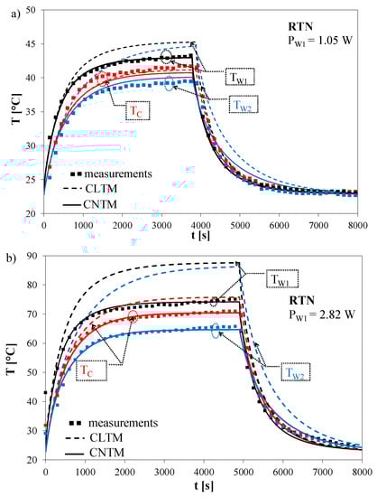
Figure 8.
Measured and calculated temperature waveforms of the components of a transformer with a toroidal nanocrystalline core (RTN) at dissipated powers PW1 of 1.05 W (a) and 2.82 W (b) in the primary winding.
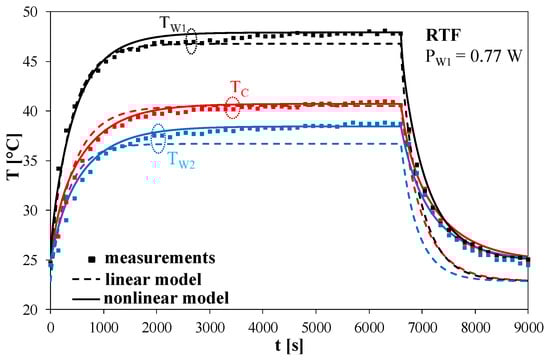
Figure 9.
Measured and calculated waveforms of the temperature of the primary winding TW1, the temperature of the secondary winding TW2 and the temperature of the core TC at a dissipated power PW1 of 0.77 W in the primary winding.

Figure 10.
Measured and calculated waveforms of the temperature of the primary winding TW1, the temperature of the secondary winding TW2 and the temperature of the core TC of the planar transformer at PW1 of 1 W in the primary winding (a) and PC of 2 W in the core (b).
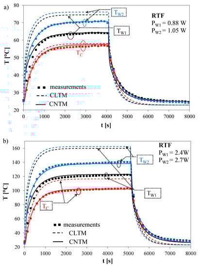
Figure 11.
Measured and calculated temperature waveforms of the primary winding TW1, the secondary winding TW2 and the core TC with simultaneous power dissipation in the windings: (a) PW1 = 0.88 W and PW2 = 1.05 W; (b) PW1 = 2.4W and PW2 = 2.7 W.
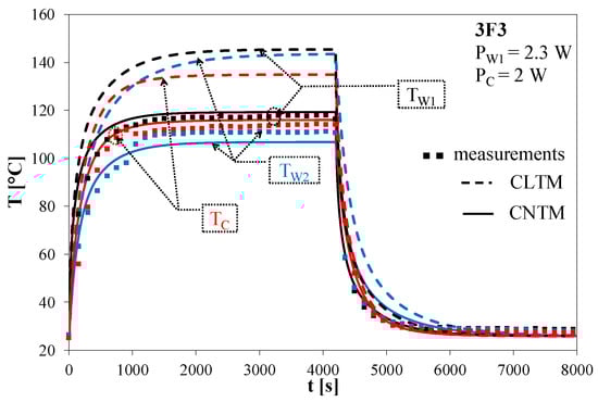
Figure 12.
Measured and calculated waveforms of the temperature of the primary winding TW1, the temperature of the secondary winding TW2 and the temperature of the core TC of the planar transformer with an impulse power PC of 2 W in the core and an impulse power PW1 of 2.3 W in the primary winding.
Calculations were performed for the values of parameters describing the nonlinear thermal model of transformers according to the principles shown in Section 3. On the other hand, for the model from [19], the values of parameters estimated at the lowest measured values of power dissipated in each component of the transformers were used.
Figure 7 presents the measured and calculated waveforms of temperatures TW1 and TC in the toroidal transformer with the RTP core at a dissipated power PW1 of 2.83 W in the primary winding.
It can be observed that the nonlinear thermal model makes it possible to obtain very good agreement between the results of calculations and measurements. In contrast, the values of the considered temperatures obtained with the use of calculations performed with the linear thermal model were higher than the results of measurements by even 40 °C.
Figure 8 shows the measured and calculated temperature waveforms of the primary winding TW1, the secondary winding TW2 and the core TC for a transformer containing an RTN. These waveforms were obtained, while the primary winding of the tested transformer was excited by a single rectangular pulse with duration times equal to 4000 s (Figure 8a) and 5000 s (Figure 8b). PW1 was 1.05 W in the case presented in Figure 8a, and PW1 was equal to 2.82 W in the case presented in Figure 8b.
As it is seen, very good agreement between the results of calculations performed with the use of the CNTM and measurements was achieved for both the values of power dissipated in this transformer. In contrast, for the linear thermal model, an excess of temperature of each component of the transformer over ambient temperature was overestimated by 10% at lower values of the considered powers and even 50% overestimated for higher values of the considered dissipated power.
Figure 9 illustrates the measured and calculated temperature waveforms of the primary winding TW1, the secondary winding TW2 and the core TC for the transformer with an RTF. The primary winding was stimulated by a single rectangular impulse with a duration time equal to 7000 s at PW1 of 0.77 W.
By analysing the temperature waveforms of the core TC, the primary winding TW1 and the secondary winding TW2 presented in Figure 9, it can be observed that the results of calculations performed by means of the nonlinear thermal model assured better agreement with the results of measurements than the results of calculations obtained by means of the model described in [19]. The obtained difference between the results of calculations performed with the use of the linear thermal model and the measurements results was 10%.
Figure 10 presents the measured and calculated waveforms of the temperature of the primary winding TW1, the temperature of the secondary winding TW2 and the core temperature TC of the planar transformer by stimulating the primary winding with a single rectangular impulse having a duration time equal to 5500 s and PW1 of 1 W (Figure 10a) and with a single rectangular impulse having a duration time of 5000 s and PC of 2 W (Figure 10b).
As one can notice, the results of calculations by means of the nonlinear thermal model assured better agreement with the results of measurements than the results of calculations performed by means of the linear thermal model. In Figure 10a, it is visible that the difference between the waveforms of temperatures TW1 and TC obtained with the use of the considered models was more than 2 °C. The biggest difference between the results of calculations was observed for temperature TW2. In Figure 10b, the considered differences were bigger than in the case presented in Figure 10a. These differences reached even 20 °C. When power was dissipated in the core only, the temperatures of both windings were nearly the same.
The results of measurements and calculations presented above corresponded to untypical situations, when power was dissipated in one of the transformer components only. Figure 11 and Figure 12 present the results of measurements and calculations of temperature waveforms of components of the selected transformers obtained in the case when power was dissipated in both the components of the selected transformers.
Figure 11 shows the measured and calculated temperature waveforms of the primary winding TW1, the secondary winding TW2 and the core TC for the transformer containing the toroidal ferrite core (RTF) when it was excited by power dissipated simultaneously in the primary and secondary windings with a single rectangular pulse having duration times equal to 4500 s (Figure 11a) and 5500 s (Figure 11b). PW1 was equal to 0.88 W and PW2 was equal to 1 W in the case presented in Figure 11a, whereas PW1 was equal to 2.4 W and PW2 was equal to 2.7 W in the case presented in Figure 11b.
By analysing temperature waveforms of the core and the windings of the transformer containing an RTF (Figure 11), it is easy to observe that the difference between the results of calculations performed using the linear thermal model and the results of measurements was up to 20 °C. In contrast, the results of calculations made using the nonlinear thermal model showed very good agreement with the results of measurements. Differences between the results of measurements and calculations performed with the linear thermal model were bigger at higher powers dissipated in the components of the transformer.
Figure 12 presents the calculated and measured waveforms of the temperatures of each component of the planar transformer by simultaneously stimulating the core and the primary winding with a single rectangular impulse having a duration time equal to 4500 s, PW1 of 2.3 W and PC of 2 W.
As one can notice, the results of calculations by means of the nonlinear thermal model assured better agreement with the results of measurements than the results of calculations performed by means of the linear thermal model. The observed differences between the results of measurements and the results of calculations performed by means of the linear thermal model exceeded even 40 °C, whereas the difference between the results of calculations performed by means of the nonlinear thermal model and the results of measurements was no more than about 5 °C. It is also worth noticing that in the considered operation conditions the temperatures of the transformer components were low and did not exceed 10 °C.
Table 4 contains the values of the maximum errors of the temperatures of transformers components δTW1, δTW2 and δTC obtained using the CLTM and the CNTM of the transformer analysed in this section.
Table 4.
Values of the maximum relative error of the temperatures of transformers components calculated with the CNTM and the compact linear thermal model (CLTM).
It is clearly seen in Table 4 that the considered relative error of calculations of temperatures obtained using the CLTM achieved 48.8% for the primary winding temperature of the transformer with an RTP core whereas such an error of calculations of the primary winding temperature obtained using the CNTM was equal to 8.16% for the same transformer. It is also worth noticing that the value of the relative error of the temperatures of transformers components obtained using the CNTM did not exceed 9% for all the considered transformers containing a toroidal core made of different materials. It was also observed that an increase in power dissipated in the transformer components caused an increase of the value of the relative error of calculations for both the considered models.
5. Conclusions
This paper describes a new CNTM of a pulse transformer elaborated by the authors. It allows determining the waveforms of the temperatures of the core and each winding. Calculations were performed by taking into account a self-heating phenomenon and mutual thermal interaction between the transformer components. In our model, the dependences of self-thermal and mutual thermal resistances depend on power dissipated in the transformer components. The proposed model was verified experimentally for transformers including ferromagnetic cores with different shapes and made of different materials. High accuracy of this model and its advantage over the CLTM were also demonstrated. The results of calculations and measurements presented in this paper also confirmed that power dissipated in the transformer components influenced mostly thermal resistance and its influence on thermal capacity was neglected.
It is also worth noticing that the obtained differences between the values of the temperatures of the transformer components can be equal to 50 °C. Such big differences justify the use different temperatures of the windings and the core in the thermal model. The linear thermal model makes it possible to obtain good agreement between the results of calculations and measurements only for very low powers dissipated in each component of the examined transformers. The nonlinear thermal model makes it possible to obtain good agreement between the results of calculations and measurements over a wide range of power dissipated in the windings or in the core of the examined transformers by considering the dependence of Rth on power.
The presented results of calculations and measurements proved that the nonlinear thermal model of a pulse transformer proposed in this paper is able to accurately describe dynamic thermal properties of the transformer including cores with different dimensions and shapes and made of different ferromagnetic materials. It was also shown that using this model one can obtain accurate results of calculations at different conditions of power dissipation in the tested transformers.
It is also worth noticing that the proposed model is universal and it can be useful for different type of transformers such as planar transformers or transformers containing a toroidal core. Additionally, this model takes into account properties of materials used to make the core. The biggest advantage of the proposed model is its simple structure and that easy implementation, e.g., in the SPICE program, which is widely used by designers of electronic circuits. In addition, analyses made with the proposed model are not time-consuming, which is very important from the economic point of view. The proposed model can be used to formulate electrothermal models of transformers, which take into account the nonlinearity of a heat removal process.
The CNTM of the pulse transformer proposed in this paper can be useful in designing switch-mode power supplies, and it can be used as a component of an electrothermal model of transformers.
Author Contributions
Conceptualization (K.G. (Krzysztof Górecki)); methodology (K.G. (Krzysztof Górecki), K.G. (Krzysztof Górski)); validation (K.G. (Krzysztof Górecki), K.D., K.G. (Krzysztof Górski)); investigation (K.G. (Krzysztof Górecki), K.G. (Krzysztof Górski)); resources (K.D.); writing—original draft preparation (K.G. (Krzysztof Górecki), K.D.); writing—review and editing (K.G. (Krzysztof Górecki), K.D.); visualization (K.G. (Krzysztof Górecki), K.G. (Krzysztof Górski)); supervision (K.G. (Krzysztof Górecki)). All authors have read and agreed to the published version of the manuscript.
Funding
The project is financed in the framework of the program by the Ministry of Science and Higher Education called “Regionalna Inicjatywa Doskonałości” in the years 2019–2022 (project number: 006/RID/2018/19; the sum of financing: 11,870,000 PLN).
Conflicts of Interest
The authors declare no conflict of interest.
Abbreviations and Notations
| Rth | thermal resistance |
| Cth | thermal capacitance |
| TW1 | the temperature of the transformer primary winding |
| TW2 | the temperature of the transformer secondary winding |
| TC | the temperature of the transformer core |
| Ta | ambient temperature |
| Zth(t) | transient thermal impedance |
| τthi | thermal time constant |
| ai | the dimensionless coefficient corresponding to a thermal time constant |
| N | the number of thermal time constants |
| RTP | toroidal powdered iron core |
| RTN | toroidal nanocrystalline core |
| RTF | toroidal ferrite core |
| SPICE | Simulation Program with Integrated Circuits Emphasis |
| CNTM | compact nonlinear thermal model |
| CLTM | compact linear thermal model |
| ANSYS | engineering simulation and 3D design software |
References
- Rashid, M.H. Power Electronic Handbook; Academic: New York, NY, USA, 2007. [Google Scholar]
- Erickson, R.; Maksimović, D. Fundamentals of Power Electronics; Springer Science and Business Media LLC: Berlin/Heidelberg, Germany, 2001. [Google Scholar]
- Basso, C. Switch-Mode Power Supply SPICE Cookbook; McGraw-Hill: New York, NY, USA, 2001. [Google Scholar]
- Barlik, R.J.; Nowak, K.M. Energoelektronika. Elementy Podzespoły, Układy; Oficyna Wydawnicza Politechniki Warszawskiej: Warszawa, Poland, 2014. [Google Scholar]
- Kazimierczuk, M.K. Pulse-Width Modulated DC-DC Power Converters; Wiley: Hoboken, NJ, USA, 2008. [Google Scholar]
- Magambo, J.S.N.T.; Bakri, R.; Margueron, X.; Le Moigne, P.; Mahe, A.; Guguen, S.; Bensalah, T. Planar Magnetic Components in More Electric Aircraft: Review of Technology and Key Parameters for DC–DC Power Electronic Converter. IEEE Trans. Transp. Electrif. 2017, 3, 831–842. [Google Scholar] [CrossRef]
- Górecki, K.; Górski, K.; Zarębski, J. Investigations on the Influence of Selected Factors on Thermal Parameters of Impulse-Transformers. Inf. MIDEM J. Microelectron. Electron. Compon. Mater. 2017, 47, 3–13. [Google Scholar]
- Detka, K.; Górecki, K.; Zarębski, J. Modeling Single Inductor DC–DC Converters with Thermal Phenomena in the Inductor Taken Into Account. IEEE Trans. Power Electron. 2017, 32, 7025–7033. [Google Scholar] [CrossRef]
- Maksimovic, D.; Stankovic, A.; Thottuvelil, V.; Verghese, G. Modeling and simulation of power electronic converters. Proc. IEEE 2001, 89, 898–912. [Google Scholar] [CrossRef]
- Wilson, P.; Ross, J.; Brown, A. Simulation of magnetic component models in electric circuits including dynamic thermal effects. IEEE Trans. Power Electron. 2002, 17, 55–65. [Google Scholar] [CrossRef]
- Tsili, M.A.; Amoiralis, E.I.; Kladas, A.; Souflaris, A.T. Power transformer thermal analysis by using an advanced coupled 3D heat transfer and fluid flow FEM model. Int. J. Therm. Sci. 2012, 53, 188–201. [Google Scholar] [CrossRef]
- Valchev, V.C.; Bossche, A.V.D. Inductors and Transformers for Power Electronics; Informa UK Limited: London, UK, 2018. [Google Scholar]
- Castellazzi, A.; Gerstenmaier, Y.; Kraus, R.; Wachutka, G. Reliability analysis and modeling of power MOSFETs in the 42-V-PowerNet. IEEE Trans. Power Electron. 2006, 21, 603–612. [Google Scholar] [CrossRef]
- Narendran, N.; Gu, Y. Life of LED-Based White Light Sources. J. Disp. Technol. 2005, 1, 167–171. [Google Scholar] [CrossRef]
- Górecki, K.; Zarębski, J.; Górecki, P.; Ptak, P. Compact thermal models of semiconductor devices–a review. Int. J. Electron. Telecommun. 2019, 65, 151–158. [Google Scholar]
- Janicki, M.; Sarkany, Z.; Napieralski, A. Impact of nonlinearities on electronic device transient thermal responses. Microelectron. J. 2014, 45, 1721–1725. [Google Scholar] [CrossRef]
- Górecki, K.; Rogalska, M. The compact thermal model of the pulse transformer. Microelectron. J. 2014, 45, 1795–1799. [Google Scholar] [CrossRef]
- Penabad-Duran, P.; López-Fernández, X.; Turowski, J. 3D non-linear magneto-thermal behavior on transformer covers. Electr. Power Syst. Res. 2015, 121, 333–340. [Google Scholar] [CrossRef]
- Górecki, K.; Gorski, K. Compact thermal model of planar transformers. In Proceedings of the 2017 MIXDES-24th International Conference Mixed Design of Integrated Circuits and Systems, Bydgoszcz, Poland, 22–24 June 2017; Institute of Electrical and Electronics Engineers (IEEE): Piscataway, NJ, USA, 2017; pp. 345–350. [Google Scholar]
- Gamil, A.; Al-Abadi, A.; Schatzl, F.; Schlucker, E. Theoretical and Empirical-Based Thermal Modelling of Power Transformers. In Proceedings of the 2018 IEEE International Conference on High Voltage Engineering and Application (ICHVE), Athens, Greece, 10–13 September 2018; IEEE: Piscataway, NJ, USA, 2018; pp. 1–4. [Google Scholar] [CrossRef]
- Souza, L.; Lemos, A.; Caminhas, W.; Boaventura, W. Thermal modeling of power transformers using evolving fuzzy systems. Eng. Appl. Artif. Intell. 2012, 25, 980–988. [Google Scholar] [CrossRef]
- Tang, W.H.; Wu, Q.H.; Richardson, Z.J. A simplified transformer thermal model based on thermal–electric analogy. IEEE Trans. Power Deliv. 2004, 19, 1112–1119. [Google Scholar] [CrossRef]
- Tang, W.; Wu, Q.H.; Richardson, Z. Equivalent heat circuit based power transformer thermal model. IEE Proc.-Electr. Power Appl. 2002, 149, 87. [Google Scholar] [CrossRef]
- Swift, G.; Molinski, T.S.; Bray, R. A fundamental approach to transformer thermal modeling. Part I: Theory and equivalent circuit. IEEE Trans. Power Deliv. 2001, 16, 171–175. [Google Scholar] [CrossRef]
- Haritha, V.; Rao, T.; Amit Jain Ramamoorty, E. Thermal Modeling of Electrical Transformers. In Proceedings of the 16th National Power Systems Conference, Hyderabad, India, 15–17 December 2010; pp. 597–602. [Google Scholar]
- Bissuel, V.; Codecasa, L.; Monier-Vinard, E.; Rogie, B.; Olivier, A.; Mahe, A.; Laraqi, N.; Dralessandro, V.; Gougis, C. Novel Approach to the Extraction of Delphi-like Boundary-Condition-Independent Compact Thermal Models of Planar Transformer Devices. In Proceedings of the 2018 24rd International Workshop on Thermal Investigations of ICs and Systems (THERMINIC), Stockholm, Sweden, 26–28 September 2018; Institute of Electrical and Electronics Engineers (IEEE): Piscataway, NJ, USA, 2018; pp. 1–7. [Google Scholar]
- Lopez, G.S.; Exposito, A.D.; Muñoz-Antón, J.; Ramirez, J.A.O.; Lopez, R.P.; Delgado, A.; Oliver, J.A.; Prieto, R. Fast and Accurate Thermal Modeling of Magnetic Components by FEA-Based Homogenization. IEEE Trans. Power Electron. 2020, 35, 1830–1844. [Google Scholar] [CrossRef]
- Vansompel, H.; Yarantseva, A.; Sergeant, P.; Crevecoeur, G. An Inverse Thermal Modeling Approach for Thermal Parameter and Loss Identification in an Axial Flux Permanent Magnet Machine. IEEE Trans. Ind. Electron. 2018, 66, 1727–1735. [Google Scholar] [CrossRef]
- De-La-Hoz, D.; Salinas, G.; Svikovic, V.; Alou, P. Simplification of thermal networks for magnetic components in space power electronics. Energies 2020, in press. [Google Scholar]
- Monier-Vinard, E.; Bissuel, V.; Laraqi, N.; Dia, C. Latest developments of compact thermal modeling of system-in-package devices by means of Genetic Algorithm. In Proceedings of the Fourteenth Intersociety Conference on Thermal and Thermomechanical Phenomena in Electronic Systems (ITherm), Orlando, FL, USA, 27–30 May 2014; Institute of Electrical and Electronics Engineers (IEEE): Piscataway, NJ, USA, 2014; pp. 998–1006. [Google Scholar]
- Rogie, B.; Codecasa, L.; Monier-Vinard, E.; Bissuel, V.; Laraqi, N.; Daniel, O.; D’Amore, D.; Magnani, A.; Dralessandro, V.; Rinaldi, N. Delphi-like dynamical compact thermal models using model order reduction. In Proceedings of the 2017 23rd International Workshop on Thermal Investigations of ICs and Systems (THERMINIC), Amsterdam, The Netherlands, 27–29 September 2017; pp. 1–6. [Google Scholar] [CrossRef]
- Shen, Z.; Shen, Y.; Liu, B.; Wang, H. Thermal Coupling and Network Modeling for Planar Transformers. In Proceedings of the 2018 IEEE Energy Conversion Congress and Exposition (ECCE), Portland, OR, USA, 23–27 September 2018; pp. 3527–3533. [Google Scholar] [CrossRef]
- Górecki, K.; Godlewska, M. Modelling characteristics of the impulse transformer in a wide frequency range. Int. J. Circuit Theory Appl. 2020, 48, 750–761. [Google Scholar] [CrossRef]
- Yener, Y.; Kakac, S. Heat Conduction; Taylor & Francis: Abingdon, UK, 2008. [Google Scholar]
- Górecki, K.; Zarębski, J. Modeling the Influence of Selected Factors on Thermal Resistance of Semiconductor Devices. IEEE Trans. Compon. Packag. Manuf. Technol. 2014, 4, 421–428. [Google Scholar] [CrossRef]
- Gorecki, K.; Gorecki, P. A new form of the non-linear compact thermal model of the IGBT. In Proceedings of the 2018 IEEE 12th International Conference on Compatibility, Power Electronics and Power Engineering (CPE-POWERENG 2018), Doha, Qatar, 10–12 April 2018; Institute of Electrical and Electronics Engineers (IEEE): Piscataway, NJ, USA, 2018; pp. 1–6. [Google Scholar]
- Górecki, K.; Górski, K. Non-linear thermal model of planar transformers. In Proceedings of the 2017 21st European Microelectronics and Packaging Conference (EMPC) & Exhibition, Warsaw, Poland, 10–13 September 2017; Institute of Electrical and Electronics Engineers (IEEE): Piscataway, NJ, USA, 2017. [Google Scholar]
- Gorecki, K.; Detka, K. The Nonlinear Compact Thermal Model of the Pulse Transformer. In Proceedings of the 2019 25th International Workshop on Thermal Investigations of ICs and Systems (THERMINIC), Lecco, Italy, 25–27 September 2019; Institute of Electrical and Electronics Engineers (IEEE): Piscataway, NJ, USA, 2019. [Google Scholar]
- Andreu, D.; Boucher, J.; Maxim, A. New SPICE behavioural macromodelling method of magnetic components including the self-heating process. In Proceedings of the IEEE Annual Power Electronics Specialist Conference PESC, Charleston, SC, USA, 1 July 1999; Volume 2, pp. 735–740. [Google Scholar]
- Górecki, K.; Gorecki, P.; Zarebski, J. Measurements of Parameters of the Thermal Model of the IGBT Module. IEEE Trans. Instrum. Meas. 2019, 68, 4864–4875. [Google Scholar] [CrossRef]
- Górecki, K.; Rogalska, M.; Zarębski, J. Parameter estimation of the electrothermal model of the ferromagnetic core. Microelectron. Reliab. 2014, 54, 978–984. [Google Scholar] [CrossRef]
© 2020 by the authors. Licensee MDPI, Basel, Switzerland. This article is an open access article distributed under the terms and conditions of the Creative Commons Attribution (CC BY) license (http://creativecommons.org/licenses/by/4.0/).