Article

Fuzzy Logic Energy Management Strategy of a Multiple Latent Heat Thermal Storage in a Small-Scale Concentrated Solar Power Plant †

1
DIAEE, Sapienza Università di Roma, 00185 Rome, Italy
2
CREAT, Università Telematica eCampus, 22060 Novedrate, Italy
3
DIISM, Università Politecnica delle Marche, 60131 Ancona, Italy
4
Department of Mechanical Engineering, KU Leuven, B-3000 Leuven, Belgium
*
Author to whom correspondence should be addressed.
This paper is an extended version of our paper published in Proceedings of ECOS 2019—The 32nd International conference on efficiency, cost, optimization, simulation and environmental impact of energy systems, 23–28 June, Wroclaw, Poland.
Energies 2020, 13(11), 2733; https://doi.org/10.3390/en13112733
Submission received: 29 April 2020 / Revised: 21 May 2020 / Accepted: 26 May 2020 / Published: 29 May 2020

Abstract

:
Latent heat thermal energy storage (LHTES) systems allow us to effectively store and release the collected thermal energy from solar thermodynamic plants; however, room for improvements exists to increase their efficiency when in operation. For this reason, in this work, a smart management strategy of an innovative LHTES in a micro-scale concentrated solar combined heat and power plant is proposed and numerically investigated. The novel thermal storage system, as designed and built by the partners within the EU funded Innova MicroSolar project, is subdivided into six modules and consists of 3.8 tons of nitrate solar salt kNO3/NaNO3, whose melting temperature is in the range 216 ÷ 223 °C. In this study, the partitioning of the storage system on the performance of the integrated plant is evaluated by applying a smart energy management strategy based on a fuzzy logic approach. Compared to the single thermal energy storage (TES) configuration, the proposed strategy allows a reduction in storage thermal losses and improving of the plant’s overall efficiency especially in periods with limited solar irradiance. The yearly dynamic simulations carried out show that the electricity produced by the combined heat and power plant is increased by about 5%, while the defocus thermal losses in the solar plant are reduced by 30%.

Graphical Abstract

1. Introduction

The building sector accounts for about 40% of the final energy consumption and 36% of CO2 emissions in Europe [1]. In order to curb the share of the sector on the final energy consumption and the related environmental impact, the European Union is pushing towards an improvement in the energy efficiency of buildings and an increase in renewable energy technologies’ penetration into the grid [2]. Among the different renewable energy technologies, Concentrated Solar Power (CSP) plants in combination with Combined Heat and Power (CHP) systems [3] are foreseen as a valuable alternative to substitute thermal and electric power generation from fossil fuels. So far, a good contribution in this direction has been given by the introduction of concentrated evacuated tube collectors due to their optimal compromise between cost and conversion efficiency, promoted by recent progress in manufacturing [4]. One way to convert low and mid-temperature energy sources into power may be represented by the adoption of Organic Rankine Cycle (ORC) systems that can be also easily inserted in cascade with other systems to produce cooling effect [5], even at small scale in combination with a solar source [6]. However, in order to achieve higher conversion efficiencies and annual performance of ORC systems, solar technologies with higher concentration ratio than Compound Parabolic Collectors (CPC) are required [7]. Recently, many researchers are working in this field. For example, Xu et al. [8] assessed the performance of a Linear Fresnel Reflector LFR-ORC system through a theoretical and simulation study. In particular, they showed the effect on the performance on ORC driven by an LFR middle-high temperature solar concentrator. Petrollese et al. [9], instead, evaluated the optimal design parameters to minimize the energy production cost of a hybrid CSP-PV (photovoltaic) plant based on LFR technology and using ORC power block for two different locations. The results proved that independently from the locations under investigation, such a hybridization becomes cost-effective when a constant power output is required for periods longer than 16 h/day.
At residential level, micro-cogeneration has a very interesting potential [10], and thermal power output from ORC systems can be usefully recovered for domestic hot water or space heating purposes [11]. Given that energy production from solar technologies and user demand are not always simultaneous, thermal energy storage (TES) systems are required to decouple them and usefully extend the operation of solar plants. At present, sensible heat TES are commonly adopted at a low temperatures range [12], whilst at medium-high temperature range, latent heat thermal energy storage (LHTES) systems are preferred. For example, Manfrida et al. [13] mathematically investigated a LHTES in application to a solar power ORC over one week period. The authors found that the proposed plant was able to generate power for almost 80% of the simulated period, with a weekly average overall solar-to-electricity efficiency of 3.9%. At the same time, they pointed out that appropriate control logics are required to improve the performance of the system over a more extended period. An interesting approach is represented by the TES conceptualization in several temperature levels, each one suitable for the respective section of the plant where it is installed. For example, Sebastian et al. [14] developed an innovative management strategy of a thermal storage system with molten salts for a solar plant with LFR conceived to reduce the part-load inefficiency due to the reorientation of the LFR solar field from NS to EW. The authors propose to divide the storage into three parts, each one working at a different temperature level, thus providing a wide range of possible operation strategies by combining them in series. In another study, Horst et al. [15] reported experimental and numerical results from an investigation of cascade latent heat storages with alkali nitrate salts (i.e., NaNO3, KNO3) designed for a temperature range from 250 to 500 °C.
Managing LHTES efficiently is a crucial point in optimizing the operation of solar energy based ORC systems. Indeed, an increase in the working fluid inlet temperature to the expander of the ORC unit entails higher electric conversion efficiency, but at the same time, it leads to higher thermal losses from the storage envelope to the ambient. Moreover, in the case of LHTES, the collected thermal energy is more efficiently recovered in the melting temperature range of the phase change material, and thus, it is convenient, limiting its proper operation in this interval. Before this study, the authors analyzed the performance of a micro solar CHP plant for residential applications with a LHTES in different seasons [16] and they found out some weak points in the operation of the system, especially when working at low temperature levels, because the low enthalpy energy stored was systematically lost. Considering this issue, it has been conceived a novel way to increase the storage efficiency of such LHTES by means of its subdivision in modules to be properly managed. Among all the possible control approaches, a fuzzy logic controller has been considered very suitable for the highlighted needs. Fuzzy logic control has been widely used in several applications, showing good results. For example, it has been adopted for batteries in hybrid vehicles [17], for systems that store simultaneously sensible heat from solar and electric energy [18], for reducing the operating cost of microgrids by regulating the power output of energy storage [19], for prioritization of energy storage technologies [20] and in renewable energy systems in general [21].
Smart fuzzy logic control could potentially increase the overall annual performance of a micro solar CHP plant, because it acts predominantly in reducing thermal losses. In particular, a cascade fuzzy logic controller, which manages the thermal storage connections, has been considered for the micro solar plant already modeled by the authors in previous studies [16,22,23]. It consists of a 2 kWe concentrated solar ORC system coupled with a LHTES equipped with reversible heat pipes [24], which is going to be tested in the city of Almatret, Spain, under the framework of the H2020 Innova MicroSolar project [25], made up of a consortium of three EU Universities and six EU companies, coordinated by Northumbria University. With reference to the LHTES, it consists of 3.8 tons of Solar Salt, whose melting temperature is in the range 216–223 °C [26].
To the best of the authors’ knowledge, some studies in the literature already addressed the influence of TES subdivision [14,27], as described above, but none of them referred to subdivided LHTES (sub-LHTES) operated with fuzzy logic control. Therefore, in this paper, the authors apply this logic to investigate the effects of the storage subdivision and its smart management on the performance of the overall plant. Hence, the main novelties of the work rely on: (i) the development of a fuzzy logic approach to sub-LHTES systems; (ii) the assessment of the influence of the smart management of the sub-LHTES on the performance of the small-scale integrated plant and its comparison with the system in its standard configuration.
Hence, after the introduction, Section 2 briefly reports the methodology of the work, Section 2.1 describes the global system where the new control logic is tested, Section 2.2 illustrates the sub-LHTES model on which this study is based and Section 2.3, the fuzzy logic control in detail. In Section 3, the effects of the sub-LHTES smart management on the performance of the integrated system are reported and eventually, in Section 4, the main conclusions are drawn.

2. Methodology

A dynamic model of the Innova MicroSolar plant was developed in Matlab/Simulink [28] and the performance of the integrated system assessed in terms of electric and thermal efficiency and energy production. The control logic implemented into the model aims at producing electricity at its maximum, whilst the thermal load is considered as a by-product, which can be usefully collected by final users. In particular, the cascade fuzzy logic controller has been implemented to improve the operational management of the thermal storage with the purpose of increasing the global performance of the plant. Eventually, the obtained performance of the integrated system is compared with that of the plant operating at the same ambient conditions, but with a single LHTES without a smart control management.

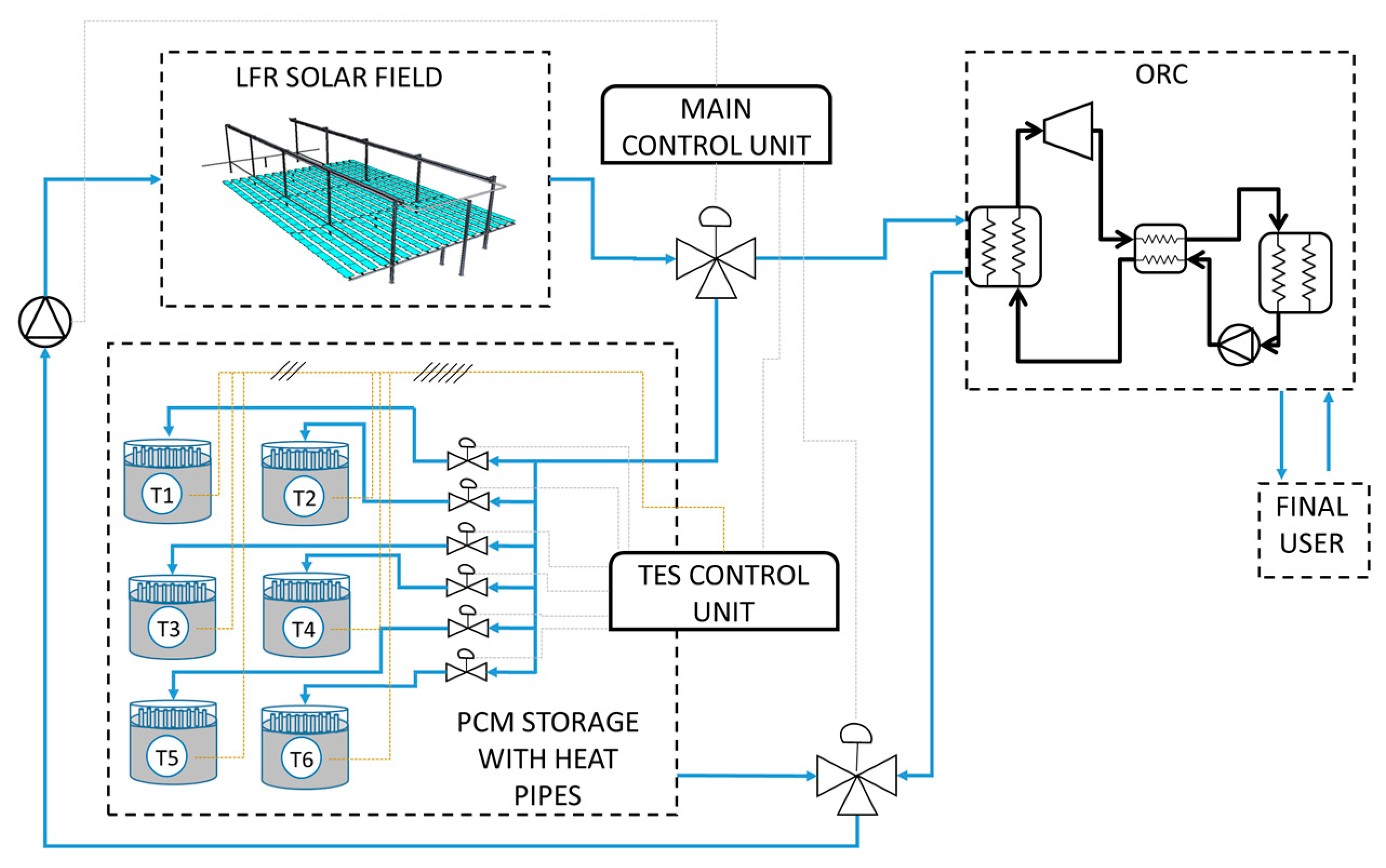
2.1. The Micro Solar CHP Model

The following main components have been included into the model: (i) the LFR solar field; (ii) the micro ORC plant; and (iii) the Phase Change Material (PCM) thermal energy storage tank equipped with reversible heat pipes. Specific subroutines for the LFR solar field, the ORC unit and the PCM storage tank equipped with heat pipes have been developed by the authors in Matlab as extensively discussed in reference [16]. In particular, the LFR and ORC subsystems are quasi-steady state models, whilst the thermal storage is a purely dynamic model. In order to take into account the thermal losses of the tubes connecting the different subsystems and the influence of their thermal inertia, a 1D longitudinal model of the pipelines has also been included, as further explored in reference [29]. The different subroutines were validated with available performance data from the manufacturers, as better discussed in reference [16].
Depending on the solar radiation and the state of charge of the LHTES, the integrated plant works according to different operation modes (OM), which are detailed in Table 1. Indeed, the diathermic oil from the solar field flows to the LHTES and/or directly to the ORC, based on its temperature and on the amount of power collected at the receiver. In the following, the different operation modes are described:
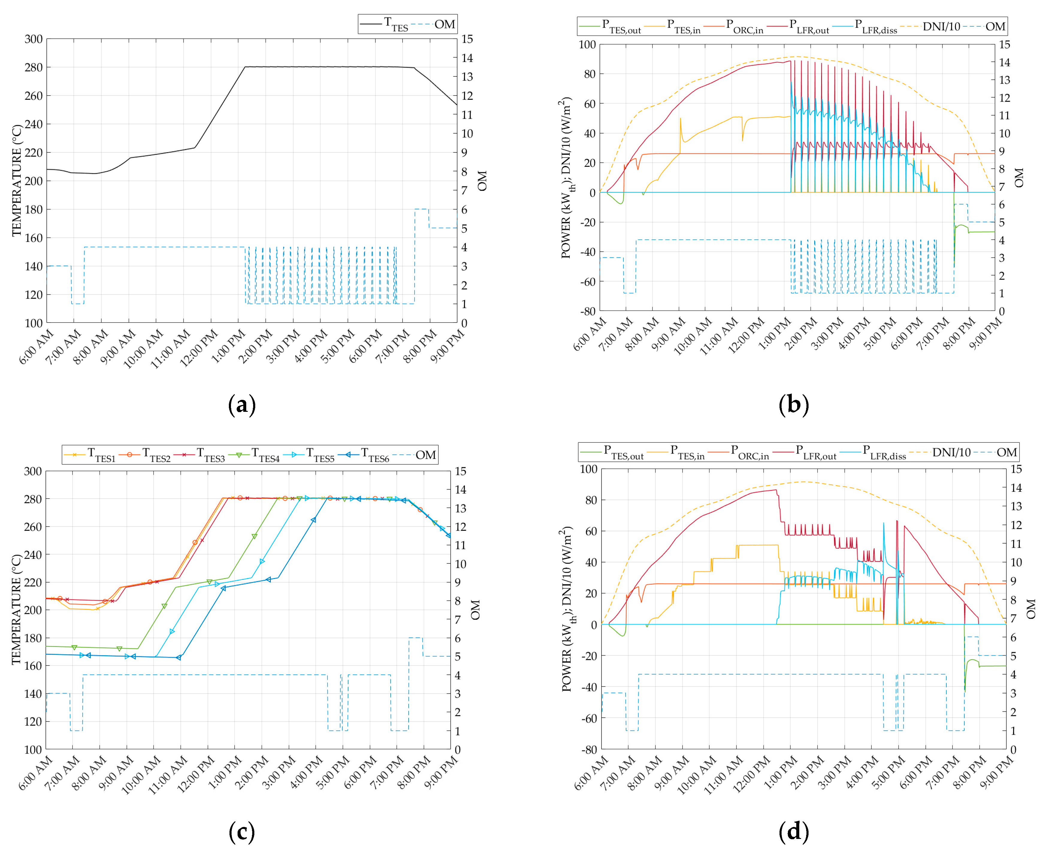
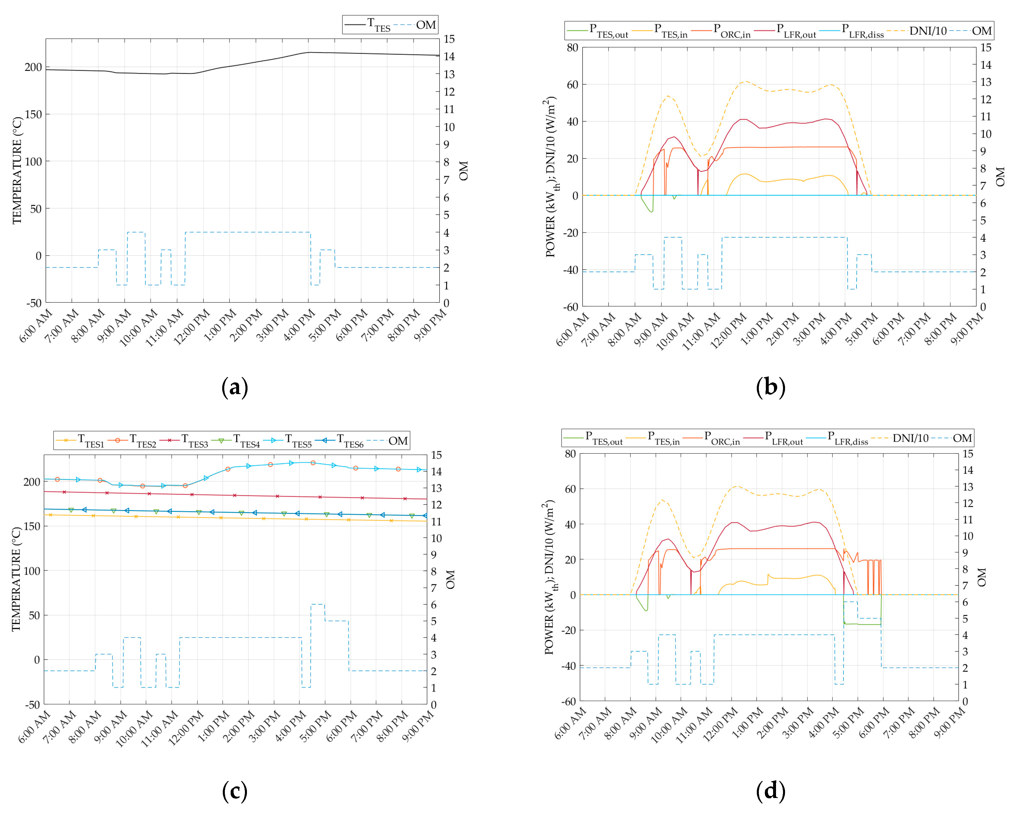
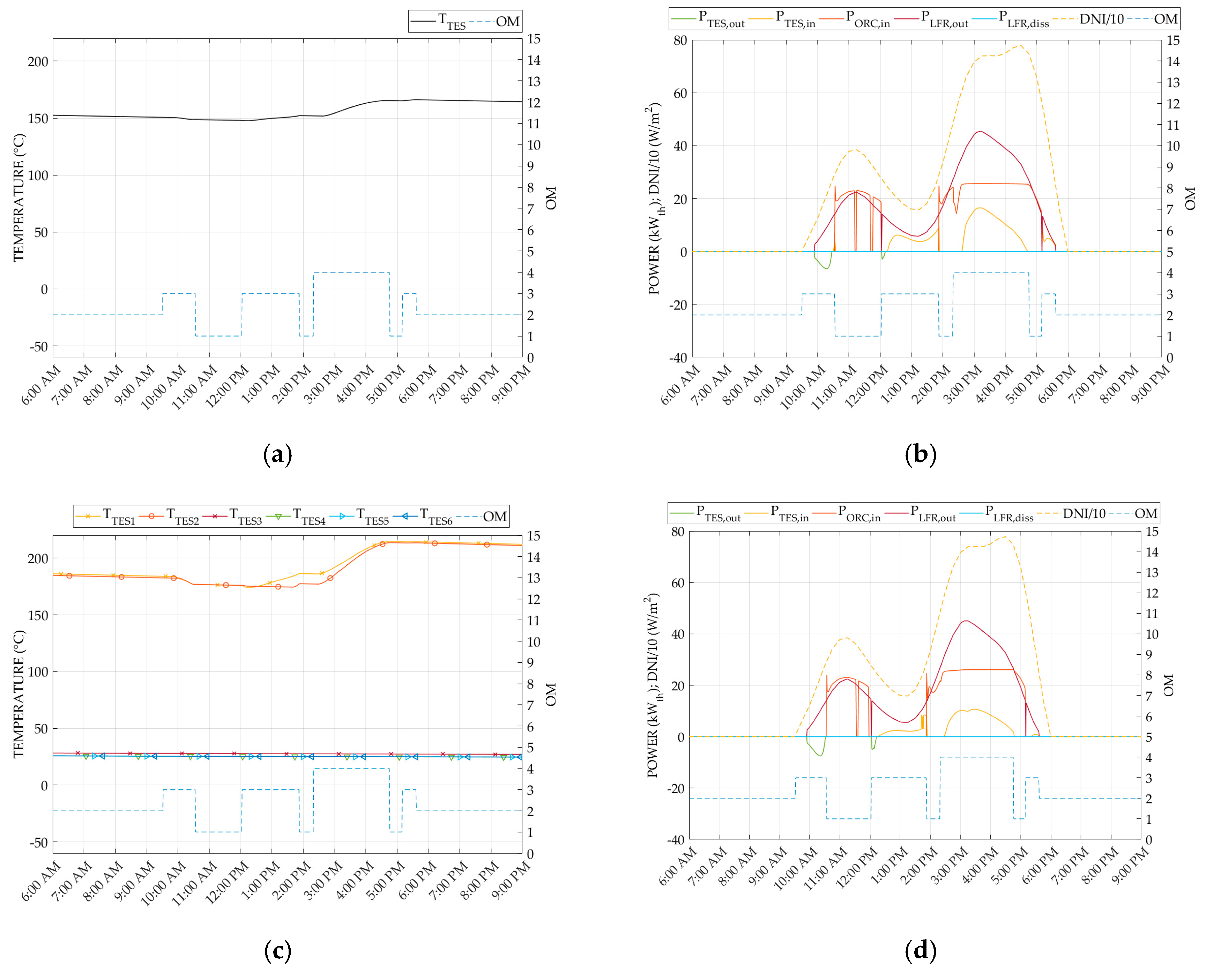
  • OM1: the oil flow rate through the LFR is adjusted to maintain 210 °C as the outlet temperature when the collected solar power is greater than 15 kWth.
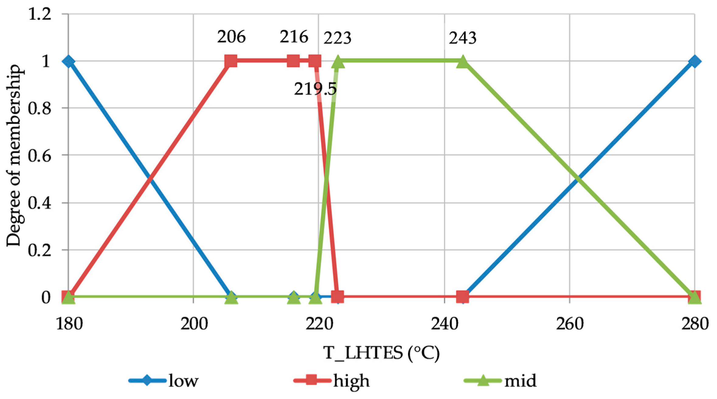
  • OM3: if the solar power is below 15 kWth, the ORC does not operate, while the thermal storage (if not fully charged, TTES,av < 215 °C) is charged and the LFR outlet temperature set-point is kept 10 °C higher than the LHTES temperature to contrast the thermal losses.
  • OM4: if the solar radiation is even higher than the power needed by the ORC, the thermal storage is also recharged and when it goes above the limit of 280 °C, defocus occurs to reduce the collected thermal power (OM1).
  • OM5 and OM6: when the power produced by the solar field is low or zero but the average TES temperature is within a given operating range (hysteresis cycle between TORC,on = 217 °C and TORC,off = 215 °C), the thermal energy of the TES can be used to run the ORC unit together with energy from the LFR (OM6) or even with no sun (OM5) for a maximum of 4 h.
In this work, the LHTES is modelled as subdivided into six modules (sub-LHTES), as reported in Figure 1, and each of them may have a distinct operation and temperature level. The TES control unit monitors their state of charge and sends signals to the main control system to choose the number of modules in operation, according to a fuzzy logic approach.
The dynamic performance of the integrated system is simulated in Matlab/Simulink for a whole year. Weather data in terms of solar radiation and ambient temperature have been taken from Meteonorm database for the city of Lerida, Spain, since it is close to the location where the prototype plant is installed.

2.2. The Thermal Storage Model

The thermal storage has been designed to guarantee 4 h of ORC unit operation with a nominal input power of 25 kW, thus a total of 100 kWh. This thermal energy storage system, as designed by Northumbria University and Aavid Thermacore [30] and investigated by the team at Lleida University [31], consists of 3.8 tons of nitrate solar salt kNO3 (40 wt.%)/NaNO3 (60 wt.%), whose melting temperature is in the range 216 ÷ 223 °C [32]. Reversible heat pipes, developed by Aavid Thermacore, enhance the heat transfer between the PCM and the heat transfer fluid. The mathematical model follows the guidelines described in the International Energy Agency IEA Task 32 report on advanced storage concepts [33], where a detailed description of Type 185 for the Trnsys simulation tool [34] is provided. The model is based on the following main assumptions: (i) material isotropic and isothermal in each internal time-step; (ii) no hysteresis and subcooling effects; and (iii) charging and discharging are not simultaneous. The presence of heat pipes is modelled by both limiting the maximum power exchanged to 40 kW and fixing a minimum temperature difference between the oil and the PCM equal to 5 °C (asymptotic condition).
Hence, the temperature variation of the PCM due to the heat exchanged can be obtained by:
Δ T TES ( t + 1 ) = Δ T TES ( t ) · e [ Δ t int timestep · f ]
where f is a function of both PCM and oil thermal properties. Then, from the temperature variation of the PCM, it is possible to calculate the heat exchanged as:
Q TES ( t + 1 ) = t t + 1 P TES ( t ) · dt
During the LHTES operation, the power released or acquired is affected by the heat exchange characteristics among diathermic oil, heat pipes and PCM material. This aspect is crucial on the performance of the whole plant, e.g., a slow or ineffective heat extraction from the thermal storage could cause LFR defocusing or low inlet temperature into the ORC inlet. For a better understanding of the power amount available at different oil temperatures, Figure 2a,b show the charging and discharging phases of the LHTES respectively:
From the figures above, it is evident the power gain available within the melting region and this is the reason why the ORC is set to operate between 215 and 217 °C (TORC,off, TORC,on, respectively). The represented charging phase refers to 3 kg/s of inlet oil flow rate at 280 °C. Similarly, during the discharging phase, PCM is initially at the maximum temperature of 280 °C and heat is removed by oil from the ORC at design conditions (oil temperature 150 °C and oil flow rate 0.22 kg/s).

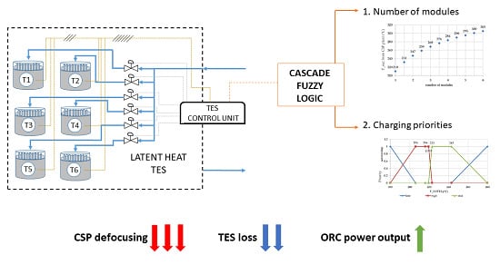
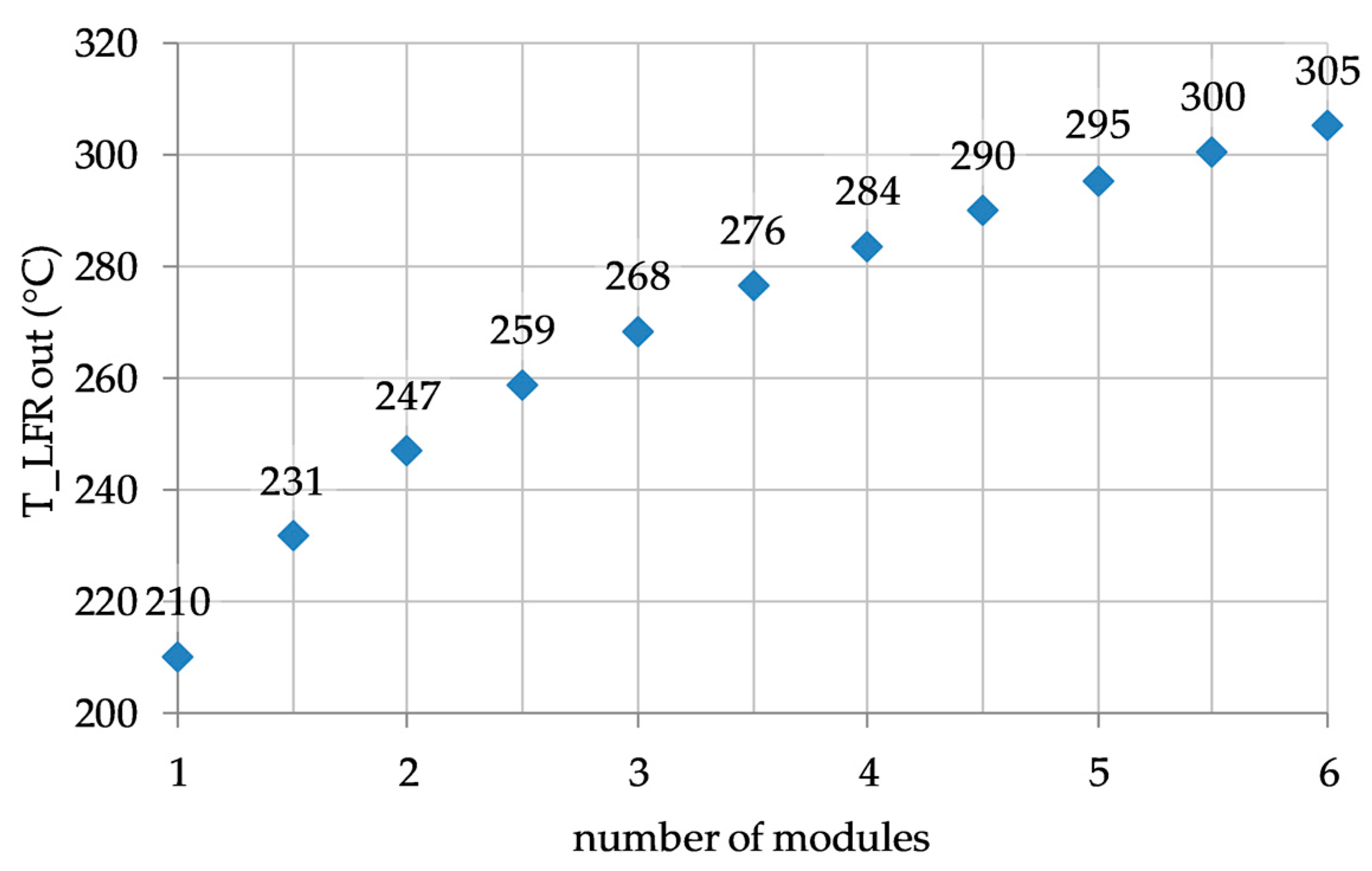
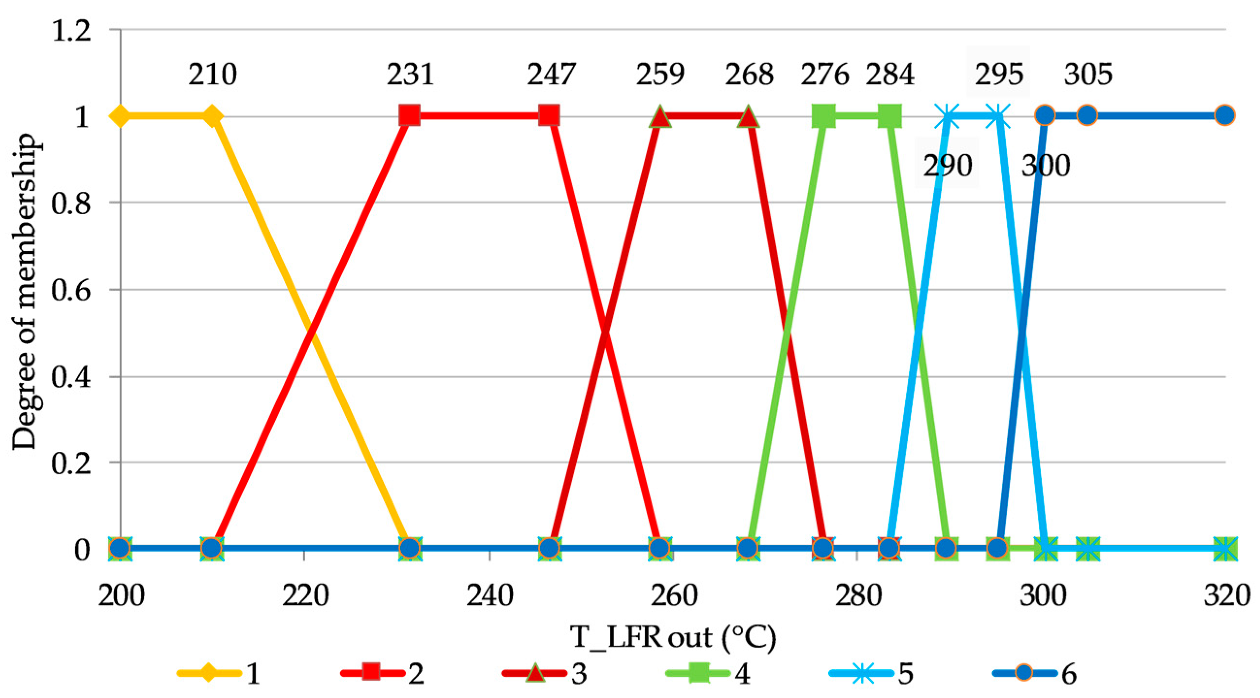
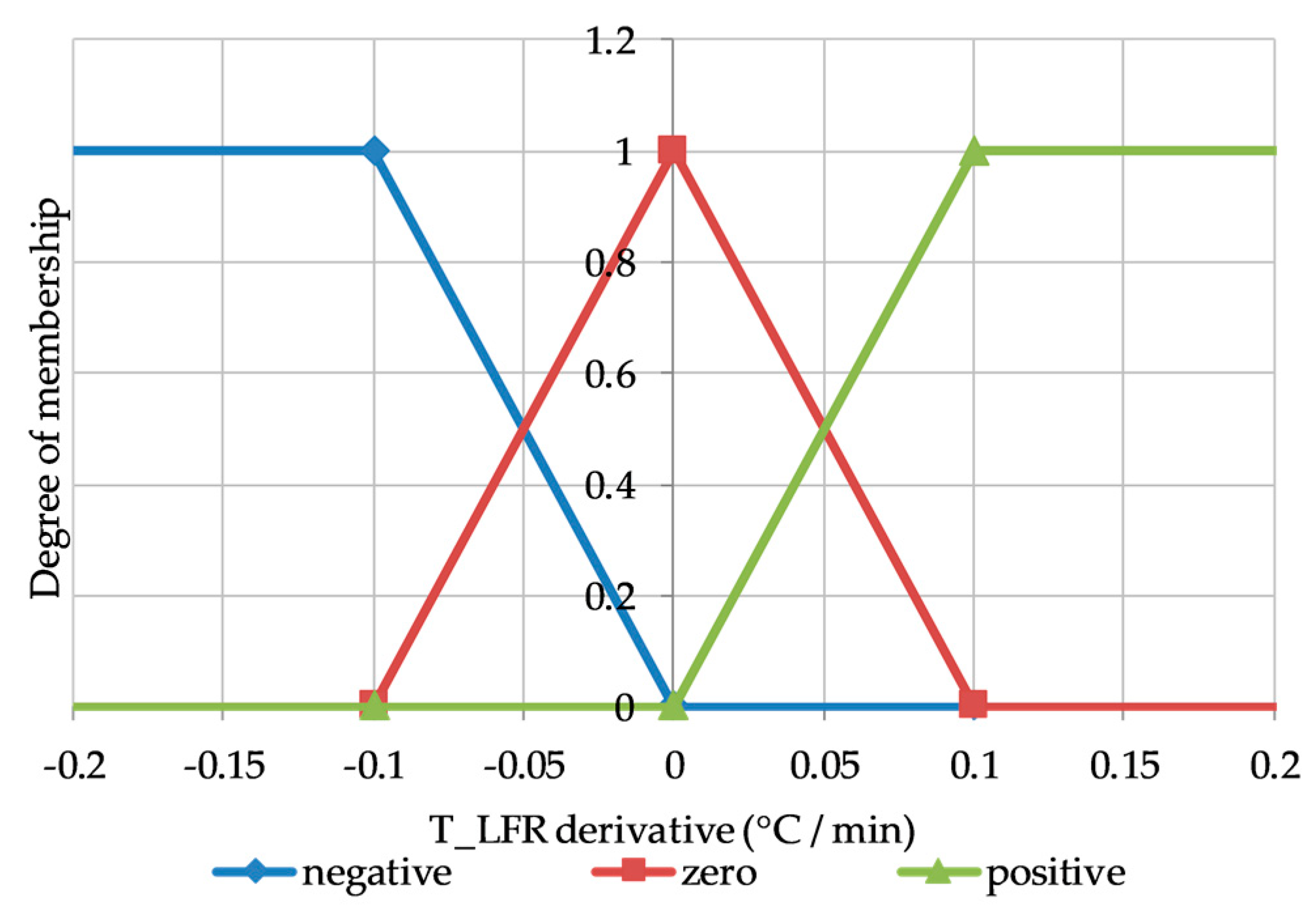
2.3. The Fuzzy Logic Controller

The fuzzy logic controller has been implemented based on the following assumptions [23]. First of all, to ensure an effective charging of the thermal storage, the LFR plant must supply oil at a temperature higher than the storage temperature to cover the thermal loss in the piping system (10 °C is the temperature difference assumed). Due to the different temperature of each module, the control system checks the maximum temperature of the current connected sub-LHTES module and supplies all the connected modules with a temperature higher than that. Secondly, during the discharging phase, corresponding to OM5 and OM6 (Table 1), the connected sub-LHTES must have a temperature suitable for the ORC supply, thereby the control system of the storage allows the connection only of the modules with a temperature higher than the temperature of the ORC inlet oil. Third, the oil flow rate is split equally among the sub-LHTES both in the charging and discharging phase.
The fuzzy logic controller has been designed according to a cascade approach to accomplish the following tasks: (i) select the number of modules to be connected with the plant; and (ii) manage each module based on a priority scale set out by the previous decision. In general, the performance of the plant can benefit from the subdivision of the LHTES. For example, when the solar radiation is high and the sub-LHTES is not fully charged, connecting a high number of modules allows mitigating of the temperature overheating of the LFR solar field, thus avoiding the inefficient defocusing of some mirrors [14]. On the contrary, when the solar radiation is low, it is convenient to connect and charge as few modules as possible so that the temperature of the storage medium is higher. Therefore, a close relationship exists between the outlet temperature of the diathermic oil from the LFR solar field and the number of modules to be connected. For this reason, a logarithmic function, shown in Figure 3, has been chosen to correlate the diathermic oil outlet temperature from the solar field with the number of modules to be connected. The LFR outlet oil temperature ranges between 210 °C, corresponding to operation mode OM1, and 305 °C, i.e., the maximum allowed temperature before defocusing. The logarithmic function was preferred since it leads to a low number of modules to be connected at low temperatures, whilst the number increases quickly at high temperatures to prevent the risk of defocusing.
The fuzzy logic decision criteria are based on the above-mentioned logarithmic function, used to define the membership functions (related in this case with the number of modules), as presented in Figure 4; it provides as output a non-integer value correlated with the final number of modules by varying the oil temperature.
Furthermore, in order to consider more accurately the changes in the diathermic oil temperature, a second parameter, i.e., its derivative with time, is included in the fuzzy logic. Therefore, the relative membership function of the controller adds a module if the derivative is positive (T_LFR derivative greater than 0.1 °C/min) or keeps the same number of modules if the derivative is zero, and finally, it reduces the number of modules in case it is negative, according to Figure 5.
Once the number of modules to be connected with the plant is assessed by the first fuzzy logic controller, a second fuzzy logic controller in cascade is applied in order to establish the working priority on the basis of the storage state of charge. The priority of charging has been chosen on the basis of the melting temperature range of the selected PCM, but also on the ORC turn on/off set points (OM5) and on the heat exchange between heat pipes and modules of the sub-LHTES.
The criteria for priority are as follows:
(i)
Charging the thermal storage at low temperature is not convenient, even if the corresponding thermal losses are negligible, and at the same time, the high difference in temperature between the PCM and the LFR outlet temperature facilitates the thermal exchange (preventing the defocusing). Indeed, rarely the received energy increases to the point that the sub-LHTES temperature is suitable for the ORC supply, and as consequence it is often lost. Thus, a low priority for this occurrence has been chosen. The low priority also occurs when the sub-LHTES is at high temperature, since the thermal losses are high, whilst the ORC unit does not benefit from this increase in temperature (there is a limit of the inlet temperature for preventing its damage). Moreover, the sub-LHTES is less prone to receive thermal energy at high temperatures, because of the low temperature difference between the PCM and the oil and, therefore, a serious risk of LFR defocusing exists.
(ii)
The highest priority occurs whenever the sub-LHTES module has a temperature close to the melting temperature range of the PCM. In this case, indeed, the thermal energy input can be exploited to run the ORC unit in OM5 and OM6.
(iii)
When the sub-LHTES is at mid-high temperature, although the storage is near the melting phase with good thermal exchange properties, thermal losses are significant and the temperature difference between the PCM and the outlet temperature of the diathermic oil from the LFR is quite low; then, it is not very convenient to charge the sub-LHTES. Therefore, a mid-priority is assigned to this condition.
The membership functions of the second fuzzy logic controller depend on the above criteria and the charging of the sub-LHTES modules occurs with the priority shown in Figure 6.
Therefore, according to the two fuzzy logic controllers in cascade described above, a matrix of identification of the modules to be connected with the plant and their priority is defined. All the identification codes are managed by an ad hoc routine, which sorts the six outputs coming from the respective fuzzy logic controllers and acts on the oil flow rate by directing it into the selected modules of the sub-LHTES.

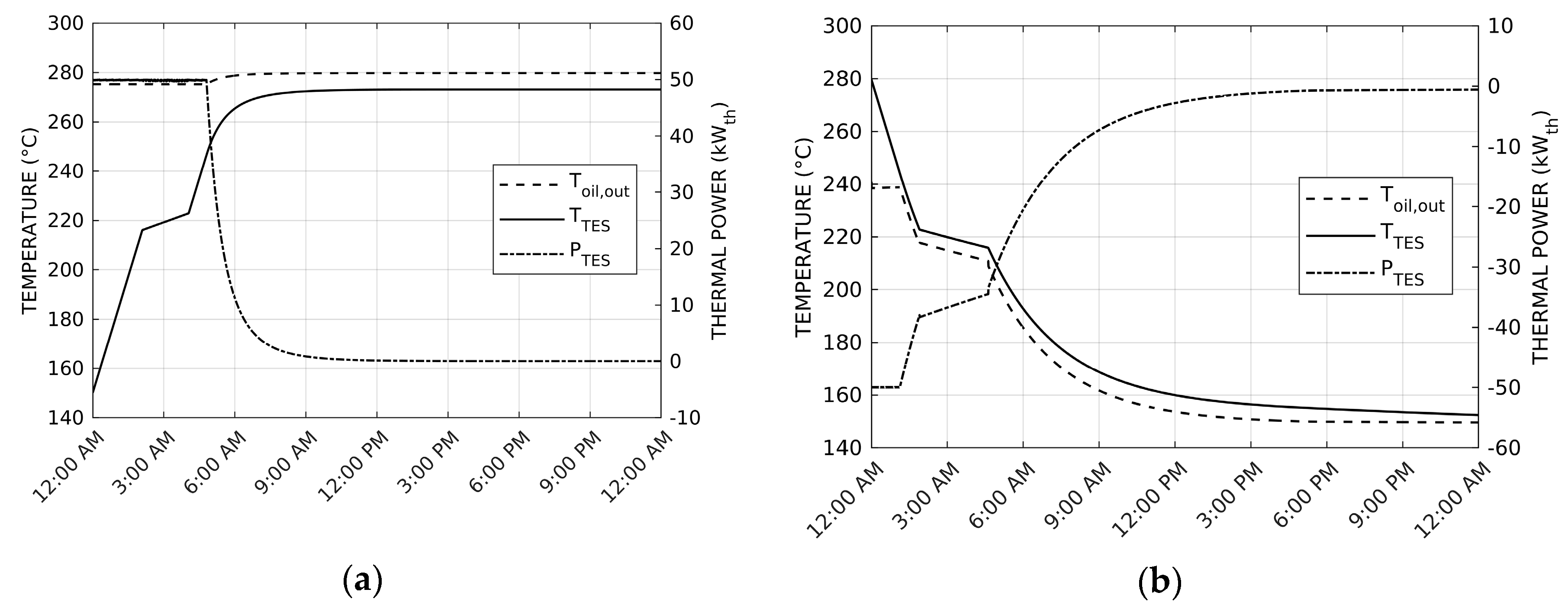
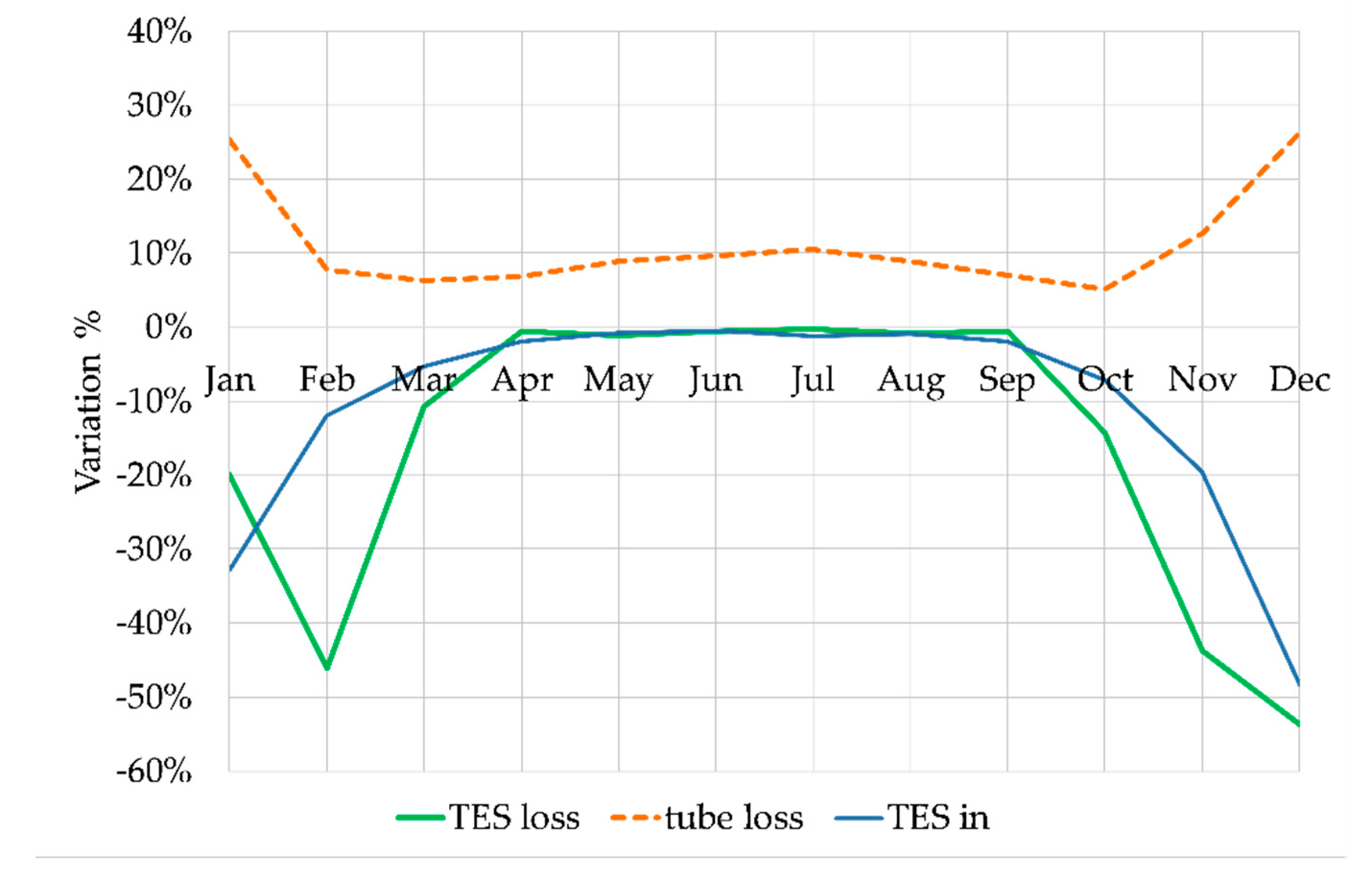
3. Results and Discussion

In this section, the performance of the system when the fuzzy logic controller is applied is investigated. The TES subdivided in modules (sub-LHTES) with the fuzzy logic controller is compared with the standard system, where the single TES is operated following only the rules described in Table 1. Firstly, the performance of the two systems is analyzed during typical days of different seasons, i.e., summer, winter and mid-season, then the monthly and yearly behavior is evaluated.
The Figure 7 shows temperature and power trends for a typical summer day. In this case, because of the intense solar radiation when the storage reaches the maximum allowed temperature of 280 °C, the system is forced to defocus and it alternates the operation mode OM1 with OM4 to maintain the storage temperature level. It is evident that the sub-LHTES involves progressively the different modules on the basis of the thermal power coming from the LFR (Figure 7c,d). At the beginning, only two modules (modules 2 and 3, chosen on the basis of the priority set by their initial temperature linked to the system dynamic the previous day) are connected to the LFR and only later, the whole storage is activated (Figure 7c). This causes a longer time for the overall storage to reach the maximum temperature in comparison with the single TES (Figure 7a), but on the other side, a better management of the LFR power is possible. Indeed, the availability of some modules at lower temperature when the solar radiation rises allows a reduction in the defocus, as demonstrated by the trend of LFR losses in Figure 7d compared to Figure 7b. Nevertheless, the overall ORC performance in summer is similar with the two TES configuration, due to the huge amount of solar energy available that brings both storages into fully charged mode.
In Figure 8, a typical mid-season day is illustrated. In this case, due to the limited solar energy available, the sub-LHTES activates only two modules, which can reach a temperature slightly higher than the single-TES. Thanks to this small increase, the heated modules reach the melting stage and the TES can contribute to supply the ORC (the plant works in OM5 and OM6 between 4:30 p.m. and 6:00 p.m.). This behavior explains the longer duration of operating modes 5 and 6 in the presence of sub-LHTES, as described later in the discussion on yearly results reported in Table 2.
Eventually, in Figure 9a typical winter day is shown. Even in this case it is possible to see that the sub-LHTES involves in the charging phase only two modules, which can increase significantly their temperature rather than the single TES, while the other modules remain cold (<50 °C, Figure 9c). This effect causes the reduction in the heat stored in the thermal storage (see P_TESin in Figure 9b,d). Nevertheless, the warm modules have a pretty high temperature, almost close to the melting condition. Thus, in case a bit more solar radiation would be available, the graphs demonstrate how easily the sub-LHTES could reach a sufficient temperature level to supply the ORC (switching on OM5 and OM6). This effect influences the better performance of the sub-LHTES in winter in comparison with the single TES, which experiences often too low temperature levels to discharge the stored heat towards the ORC.
On the basis of the priority schedule previously described in Figure 6, the module of the sub-LHTES with the highest priority should work more hours than the second one; the same behavior can be expected by the second module with respect to the third one and so on. Running a yearly dynamic simulation and recording the hours in which there is heat exchange between the n-th module and the transfer fluid, it is possible to draw the normalized histogram of Figure 10a: only three modules are used most of the time. It is confirmed by the mean temperature level of the different modules of the sub-LHTES, as shown in Figure 10b. It is also possible to observe that during wintertime, only a few modules work with a temperature above the average temperature of the single LHTES, while the others are cold and not involved in the charging phase, as already commented above.
With the purpose of showing the influence of the developed cascade fuzzy logic control on the global performance of the plant, all the parameters of interest have been compared based on a yearly simulation with and without the smart storage management (Table 2). It is evident that, thanks to a better management of the TES, its average temperature (considering the working modules) is increased in the sub-LHTES. Furthermore, even if less energy enters in the subdivided thermal storage, a higher amount of the stored energy is discharged to the ORC (TES efficiency increases of about 13%). These two aspects contribute to increase slightly the electric energy produced in the overall year (+4.7%) and also the ORC electric efficiency (+1.8%). This result is confirmed by the duration of operation mode OM5 and OM6 (i.e., when the TES discharges to the ORC, see Table 1), that are 11% longer than for the single storage. Considering both the thermal losses due to the TES and to the pipelines, they compensate each other in the sub-LHTES configuration. Indeed, the TES thermal losses are decreased due to the fact that less modules are involved in charging/discharging phases in cases of limited energy being available (thus, less mass of the storage medium), while the pipelines thermal losses are bigger because the average oil temperature is higher (with less modules involved, the charging phase is slower and the oil temperature tends to increase). Therefore, also the wasted energy through pipelines is crucial for the whole plant performance, and a good estimation of it, using accurate models, is paramount, as shown in reference [29].
Furthermore, the subdivision of the storage in the modules allows a reduction in the solar plant defocusing (about −30%): the thermal storage is better managed and more volume at lower temperature is available to store the surplus of solar energy. In Figure 11a, it is interesting to observe that the sub-LHTES causes often defocusing at low LFR power generation compared to the single LHTES, because at low solar power, less modules are connected to the plant. However, the single TES produces much more defocusing at higher LFR power generation and this causes the higher defocusing during the overall year. This behavior is supported by Figure 11b, where it is evident that modules 4, 5 and 6 work only at a high power rate compared with the others (they are colder and work only when the LFR temperature is particularly high, i.e., in cases of high temperature difference between the heat transfer fluid and the phase change material).
The analysis based on the yearly averaged values does not clearly show the exact influence of the developed fuzzy control logic on the whole performance of the plant. Therefore, the monthly trends of the main performance parameters for the LHTES are shown in Figure 12 and Table 3.
Figure 12 shows the monthly variation in percentage of the TES performance parameters in the case of smart management compared to the standard control without fuzzy logic. During the winter period, the TES subdivision enables the LFR to produce oil at higher temperature, because it stores heat in a smaller amount of PCM. The low solar radiation entails a frequent operation in OM1 and OM3, the latter one occurs with an augmented temperature which, in turn, raises the pipeline thermal losses, as clearly shown in Figure 12. The mid-season is a particular period, in fact, the temperature of several modules of the sub-LHTES is still higher than the single module, but the latter one has a stored energy reservoir not exploited (temperature below the melting point), accumulated during the past weeks. At this time, the exceeding solar energy can be easily stored and immediately released, while the sub-LHTES version uses this extra energy also to recharge the other modules that are not still in the right temperature range to run the ORC. The behavior described above affects the ORC efficiency and electricity production: a light decrease in the electricity production is observed especially in the mid-season months of March and October, while the system performs better in winter and as good as the plant with the single TES in summer.

4. Conclusions

This paper aims at evaluating the benefits provided in terms of thermal efficiency of a plant equipped with a thermal storage subdivided in several modules, while managing their operation by means of a smart fuzzy logic controller. In this case, the storage subdivision has been applied to an innovative micro solar CHP plant used in residential applications. Six sub-LHTES modules have been used and their operation has been managed according to cascade fuzzy logic control. While the main control system of the plant is designed to maximize the annual electric energy production, this further control aims at managing the sub-LHTES system only, but, as a consequence, it affects the thermal and electric energy production of the whole plant over the year. Hence, the performance of the integrated plant has been evaluated on a monthly and yearly basis and compared to that of the plant with a single LHTES (without subdivision into modules and smart management). The main findings of the comparison highlight that the proposed smart management of the sub-LHTES contributes to:
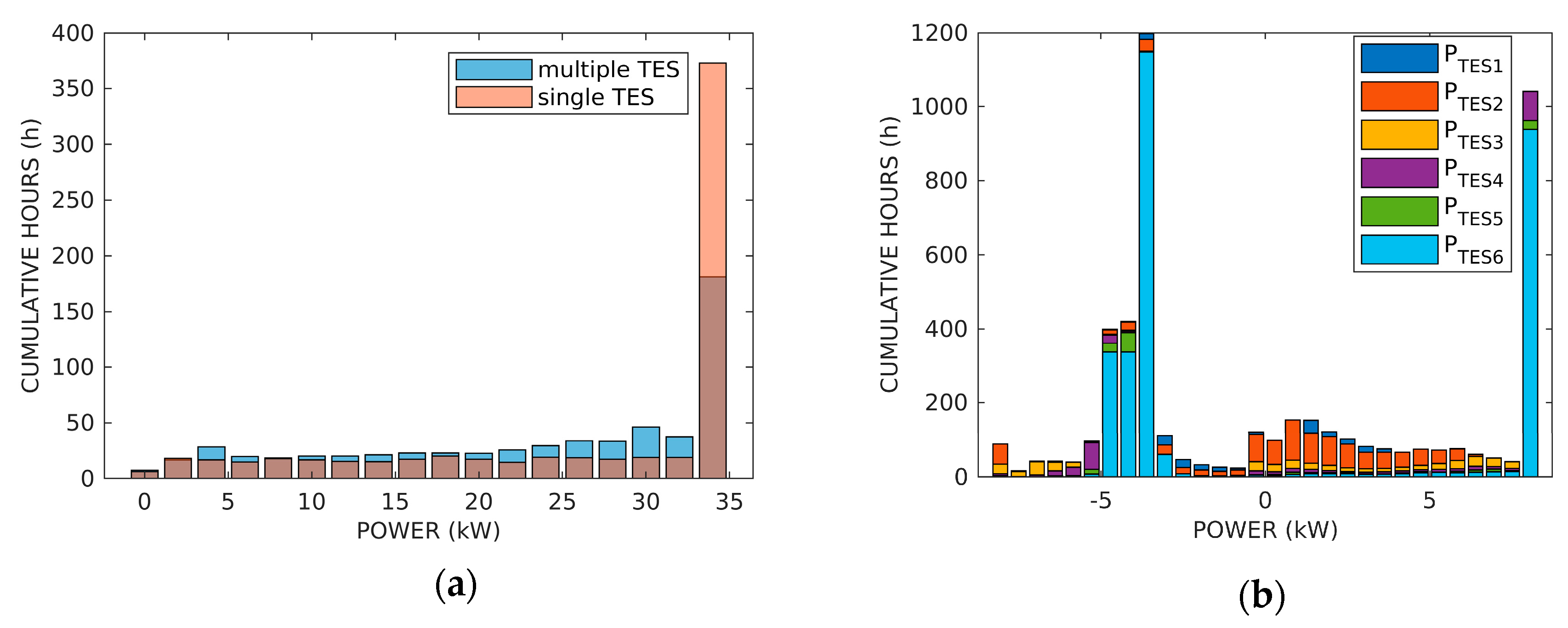
  • a significant increase in the storage efficiency during the winter season, allowing a longer duration of the discharging phase of the storage towards the ORC, while the two TES configuration behaves in a similar way in the other seasons (overall annual TES efficiency increase of 13%);
  • an electric efficiency of the ORC unit, as well as the operating time, is higher in winter, which results in an increased yearly electric energy production (about 5%);
  • 30% less thermal losses of the LFR solar field are due to defocus.
Conversely, it causes more than 9% additional thermal losses due to the higher pipeline working temperature (compensated by the increased TES efficiency mentioned above).
Concluding, the adoption of a smart control management of the sub-LHTES allows increasing the performance of an integrated micro CHP unit powered by solar energy when the plant works in part load conditions. Furthermore, it is not expected an increase in investment costs for the proposed system because the modular design of the TES is a more effective technical solution envisaged also for the standard system, thus, the real cost difference would be related mainly to some valves while the cost of the control algorithm implementation can be considered negligible. Nevertheless, further investigation is required to better estimate the exact potential of the proposed approach changing the priority ranges, and a validation of the control strategy is desirable during the forthcoming experimental tests campaign.

Author Contributions

Conceptualization, R.T.; Funding acquisition, L.C.; Methodology, R.T. and L.C.; Software, R.T.; Supervision, A.A. and L.C.; Writing—original draft, R.T.; Writing—review and editing, A.A., L.D.Z. and L.C. All authors have read and agreed to the published version of the manuscript.

Funding

This study is a part of the Innova MicroSolar Project, funded in the framework of the European Union’s Horizon 2020 Research and Innovation Programme (grant agreement No 723596).

Conflicts of Interest

The authors declare no conflict of interest.

Nomenclature

CHPCombined Heat and Power
CPCCompound Parabolic Collectors
CSPConcentrated Solar Power
DNIDirect Normal Irradiance (W/m2)
EEORC,outElectrical Energy output from the ORC unit (kJ)
LHTESLatent Heat Thermal Energy Storage
LFRLinear Fresnel Reflectors
LFRdefenergy dissipated by the LFR due to defocusing (kJ)
OMOperation Mode
ORCOrganic Rankine Cycle
ORCeffelectrical efficiency of the ORC unit (%)
ORCininlet thermal energy to the ORC (kJ)
ORCoutoutlet thermal energy from the ORC (kJ)
PLFRdisspower dissipated by the LFR due to defocusing (kW)
PLFR,outoutlet thermal power from the LFR (kW)
PORC,ininlet thermal power to the ORC (kW)
PTES,ininlet thermal power to the TES (kW)
PTES,outoutlet thermal power from the TES (kW)
PTESthermal power exchanged by the TES (kW)
PCMPhase Change Material
PVPhotovoltaic
QTESheat exchanged by the TES (kJ)
sub-LHTESSubdivided LHTES
ttime (s)
TTemperature (°C)
TESThermal Energy Storage
TTEStemperature of the TES (°C)
TTES,avaverage temperature of the TES (°C)
TESlossthermal losses of the TES (kJ)
TESininlet thermal energy to the TES (kJ)
TESoutoutlet thermal energy to the TES (kJ)
TLFR,outoutlet temperature of the oil from the LFR (°C)
TORC,ininlet temperature of the oil to the ORC (°C)
TORC,offlower bound temperature set-point of the TES (°C)
TORC,onupper bound temperature set-point of the TES (°C)
tubelossthermal losses of the tubes (kJ)
ΔTTEStemperature variation of the PCM (°C)
Δtint-timesteptime interval of the internal time step (s)
1,2,3,4,5,6number of the module of the TES

References

  1. Energy Performance of Buildings Directive|Energy. Available online: https://ec.europa.eu/energy/topics/energy-efficiency/energy-efficient-buildings/energy-performance-buildings-directive_it (accessed on 21 May 2020).
  2. Energy Union|Energy. Available online: https://ec.europa.eu/energy/topics/energy-strategy/energy-union_it (accessed on 21 May 2020).
  3. Dentice d’Accadia, M.; Sasso, M.; Sibilio, S.; Vanoli, L. Micro-combined heat and power in residential and light commercial applications. Appl. Therm. Eng. 2003, 23, 1247–1259. [Google Scholar] [CrossRef]
  4. Sabiha, M.A.; Saidur, R.; Mekhilef, S.; Mahian, O. Progress and latest developments of evacuated tube solar collectors. Renew. Sustain. Energy Rev. 2015, 51, 1038–1054. [Google Scholar] [CrossRef]
  5. Leveni, M.; Manfrida, G.; Cozzolino, R.; Mendecka, B. Energy and exergy analysis of cold and power production from the geothermal reservoir of Torre Alfina. Energy 2019, 180, 807–818. [Google Scholar] [CrossRef]
  6. Cioccolanti, L.; Tascioni, R.; Bocci, E.; Villarini, M. Parametric analysis of a solar Organic Rankine Cycle trigeneration system for residential applications. Energy Convers. Manag. 2018, 163, 407–419. [Google Scholar] [CrossRef]
  7. Villarini, M.; Tascioni, R.; Arteconi, A.; Cioccolanti, L. Influence of the incident radiation on the energy performance of two smallscale solar Organic Rankine Cycle trigenerative systems: A simulation analysis. Appl. Energy 2019, 242, 1176–1188. [Google Scholar] [CrossRef]
  8. Xu, G.; Song, G.; Zhu, X.; Gao, W.; Li, H.; Quan, Y. Performance evaluation of a direct vapor generation supercritical ORC system driven by linear Fresnel reflector solar concentrator. Appl. Therm. Eng. 2015, 80, 196–204. [Google Scholar] [CrossRef]
  9. Petrollese, M.; Cocco, D. Optimal design of a hybrid CSP-PV plant for achieving the full dispatchability of solar energy power plants. Sol. Energy 2016, 137, 477–489. [Google Scholar] [CrossRef]
  10. Comodi, G.; Cioccolanti, L.; Renzi, M. Modelling the Italian household sector at the municipal scale: Micro-CHP, renewables and energy efficiency. Energy 2014, 68, 92–103. [Google Scholar] [CrossRef]
  11. Arteconi, A.; Del Zotto, L.; Tascioni, R.; Mahkamov, K.; Underwood, C.; Cabeza, L.; Maldonado, J.; Manca, R.; Mintsa, A.; Bartolini, C.; et al. Multi-Country Analysis on Energy Savings in Buildings by Means of a Micro-Solar Organic Rankine Cycle System: A Simulation Study. Environments 2018, 5, 119. [Google Scholar] [CrossRef] [Green Version]
  12. Settino, J.; Sant, T.; Micallef, C.; Farrugia, M.; Spiteri Staines, C.; Licari, J.; Micallef, A. Overview of solar technologies for electricity, heating and cooling production. Renew. Sustain. Energy Rev. 2018, 90, 892–909. [Google Scholar] [CrossRef]
  13. Manfrida, G.; Secchi, R.; Stańczyk, K. Modelling and simulation of phase change material latent heat storages applied to a solar-powered Organic Rankine Cycle. Appl. Energy 2016, 179, 378–388. [Google Scholar]
  14. Sebastián, A.; Abbas, R.; Valdés, M.; Casanova, J. Innovative thermal storage strategies for Fresnel-based concentrating solar plants with East-West orientation. Appl. Energy 2018, 230, 983–995. [Google Scholar] [CrossRef]
  15. Michels, H.; Pitz-Paal, R. Cascaded latent heat storage for parabolic trough solar power plants. Sol. Energy 2007, 81, 829–837. [Google Scholar] [CrossRef]
  16. Cioccolanti, L.; Tascioni, R.; Arteconi, A. Mathematical modelling of operation modes and performance evaluation of an innovative small-scale concentrated solar organic Rankine cycle plant. Appl. Energy 2018, 221, 464–476. [Google Scholar]
  17. Majdi, L.; Ghaffari, A.; Fatehi, N. Control strategy in hybrid electric vehicle using fuzzy logic controller. In Proceedings of the 2009 IEEE International Conference on Robotics and Biomimetics, ROBIO 2009, Guilin, China, 19–23 December 2009; pp. 842–847. [Google Scholar]
  18. LeBreux, M.; Lacroix, M.; Lachiver, G. Fuzzy and feedforward control of an hybrid thermal energy storage system. Energy Build. 2006, 38, 1149–1155. [Google Scholar]
  19. Fossati, J.P.; Galarza, A.; Martín-Villate, A.; Echeverría, J.M.; Fontán, L. Optimal scheduling of a microgrid with a fuzzy logic controlled storage system. Int. J. Electr. Power Energy Syst. 2015, 68, 61–70. [Google Scholar] [CrossRef]
  20. Ren, J. Sustainability prioritization of energy storage technologies for promoting the development of renewable energy: A novel intuitionistic fuzzy combinative distance-based assessment approach. Renew. Energy 2018, 121, 666–676. [Google Scholar] [CrossRef]
  21. Suganthi, L.; Iniyan, S.; Samuel, A.A. Applications of fuzzy logic in renewable energy systems—A review. Renew. Sustain. Energy Rev. 2015, 48, 585–607. [Google Scholar] [CrossRef]
  22. Arteconi, A.; Del Zotto, L.; Tascioni, R.; Cioccolanti, L. Modelling system integration of a micro solar Organic Rankine Cycle plant into a residential building. Appl. Energy 2019, 251, 113408. [Google Scholar]
  23. Tascioni, R.; Cioccolanti, L.; Del Zotto, L.; Mahkamov, K.; Kenisarin, M.; Costa, C.; Cabeza, L.F.; de Gracia, A.; Maldonado, J.M.; Halimic, E.; et al. Numerical investigation of the smart energy management of modular latent heat thermal storage on the performance of a micro-solar power plant. In Proceedings of the ECOS 2019 32nd International Conference on Efficiency, Cost, Optimization, Simulation and Environmental Impact of Energy Systems, Wrocław, Poland, 23–28 June 2019. [Google Scholar]
  24. Mahkamov, K.; Pili, P.; Manca, R.; Leroux, A.; Mintsa, A.C.; Lynn, K.; Mullen, D.; Halimic, E.; Costa, S.C.; Bartolini, C.; et al. Development of a small solar thermal power plant for heat and power supply to domestic and small business buildings. In Proceedings of the American Society of Mechanical Engineers, Power Division (Publication) POWER, Lake Buena Vista, FL, USA, 24–28 June 2018. [Google Scholar]
  25. Innova-Microsolar. Available online: http://innova-microsolar.eu/ (accessed on 3 November 2017).
  26. Costa, S.C.; Mahkamov, K.; Kenisarin, M.; Lynn, K.; Halimic, E.; Mullen, D. Solar salt latent heat thermal storage for a small solar organic rankine cycle plant. In Proceedings of the ASME 2018 12th International Conference on Energy Sustainability Collocated with the ASME 2018 Power Conference and the ASME 2018 Nuclear Forum, Lake Buena Vista, FL, USA, 24–28 June 2018; Volume 142, pp. 1–9. [Google Scholar]
  27. Chacartegui, R.; Vigna, L.; Becerra, J.A.; Verda, V. Analysis of two heat storage integrations for an Organic Rankine Cycle Parabolic trough solar power plant. Energy Convers. Manag. 2016, 125, 353–367. [Google Scholar] [CrossRef]
  28. Simulink—Simulation and Model-Based Design—MATLAB & Simulink. Available online: https://www.mathworks.com/products/simulink.html (accessed on 27 February 2020).
  29. Tascioni, R.; Cioccolanti, L.; Del Zotto, L.; Habib, E. Numerical investigation of pipelines modeling in small-scale concentrated solar combined heat and power plants. Energies 2020, 13, 429. [Google Scholar] [CrossRef] [Green Version]
  30. Aavid, Thermal Division of Boyd Corporation. Available online: https://www.boydcorp.com/aavid.html (accessed on 21 May 2020).
  31. Maldonado, J.; Fullana-Puig, M.; Martín, M.; Solé, A.; Fernández, Á.; de Gracia, A.; Cabeza, L. Phase Change Material Selection for Thermal Energy Storage at High Temperature Range between 210 °C and 270 °C. Energies 2018, 11, 861. [Google Scholar]
  32. Serrano-López, R.; Fradera, J.; Cuesta-López, S. Molten salts database for energy applications. Chem. Eng. Process. 2013, 73, 87–102. [Google Scholar] [CrossRef] [Green Version]
  33. Streicher, W.; Bony, J.; Citherlet, S.; Heinz, A.; Puschnig, P.; Schranzhofer, H.; Schultz, J.M. Simulation Models of PCM Storage Units A Report of IEA Solar Heating and Cooling programme-Task 32 “Advanced Storage Concepts for Solar and Low Energy Buildings” Report C5 of Subtask C; International Energy Agency: Paris, France, 2008. [Google Scholar]
  34. TRNSYS: Transient System Simulation Tool. Available online: http://www.trnsys.com/ (accessed on 14 November 2017).
Figure 1. Schematic of the integrated system under analysis. The LHTES is shown subdivided into six sections (sub-LHTES).
Energies 13 02733 g001
Figure 2. Charging (a) and discharging (b) process of the LHTES.
Energies 13 02733 g002
Figure 3. Logarithmic correlation between number of modules and LFR output temperature. The function is T_LFR out = 210 + log_b(m), where m = 1. n (number of modules) and b = 6^(1/(Tmax − 210)) with Tmax the maximum temperature with all modules connected is 305 °C.
Energies 13 02733 g003
Figure 4. Number of working modules by varying the solar field output oil temperature.
Energies 13 02733 g004
Figure 5. Derivative component of the first fuzzy logic controller.
Energies 13 02733 g005
Figure 6. Sub-LHTES charging priorities.
Energies 13 02733 g006
Figure 7. Daily temperatures (a) and power trends (b) of the LHTES compared with the daily temperature (c) and power trends (d) of the sub-LHTES for a typical summer season day (11 June). The graphs represent also the operating mode (OM) of the plant, as specified in Table 1.
Energies 13 02733 g007
Figure 8. Daily temperatures (a) and power trends (b) of the LHTES compared with the daily temperature (c) and power trends (d) of the sub-LHTES for a typical mid-season day (11 October). The graphs represent also the operating mode (OM) of the plant, as specified in Table 1.
Energies 13 02733 g008
Figure 9. Daily temperatures (a) and power trends (b) of the LHTES compared with the daily temperature (c) and power trends (d) of the sub-LHTES for a typical winter day (30 January). The graphs represent also the operating mode (OM) of the plant, as specified in Table 1.
Energies 13 02733 g009
Figure 10. (a) Normalized working time for each module; (b) temperature trends of the six sub-LHTES modules and the single storage over the year.
Energies 13 02733 g010
Figure 11. (a) Cumulative hours of LFR defocusing in the multiple and single LHTES yearly simulation; (b) cumulative hours of power exchanged by each module.
Energies 13 02733 g011
Figure 12. Relative variation of the TES thermal performance parameters between the configuration with and without fuzzy logic.
Energies 13 02733 g012
Table 1. Operating conditions for the different operation modes of the plant.
Operation ModeDescriptionOperating Conditions
OM1LFR supplies ORCTLFR,out = 210 °C TLFR,out = 290 °C if TTES,av ≥ 280 °C (defocusing)
OM2System off-
OM3LFR supplies TESTLFR,out = TTES,av + 10 °C
OM4LFR supplies TES and ORCTLFR,out = 210 °C if TTES,av < 200 °C or TLFR,out = TTES,av + 10 °C if 200 °C ≤ TTES,av ≤ 270 °C
OM5TES supplies ORC215 °C ≤ TTES,av ≤ 217 °C and oil flow rate 0.22 kg/s
OM6TES and LFR supply ORCTLFR,out = 210 °C and oil flow rate 0.22 kg/s
Table 2. Annual energy balance and performance of the plant with and without the smart fuzzy logic controller.
ParameterSingle TES No Fuzzy LogicSub-LHTES with Fuzzy LogicVariation, %
TES in, kJ1.42 × 1081.37 × 108−3.67
TES out, kJ−1.15 × 10⁸−1.14 × 10⁸−0.38
TES eff, %65.7373.9712.53
ORC in, kJ3.38 × 1083.52 × 1084.13
TES loss, kJ3.13 × 1072.72 × 107−13.25
Time ORC on, s1.36 × 1071.41 × 1073.74
LFR def, kJ4.75 × 1073.26 × 107−31.39
T TES av, °C199.60210.705.56
T ORC in, °C228.24235.803.32
tube loss, kJ−5.45 × 10⁷−5.97 × 1079.56
ORC out, kJ2.45 × 1082.55 × 1084.09
EE ORC out, kJ2.63 × 1072.75 × 1074.68
ORC eff, %7.487.621.80
Table 3. Monthly performance of the ORC unit in the presence of single TES or subdivided TES.
MonthSingle TES No Fuzzy Logic, %Sub-LHTES with Fuzzy Logic, %
ORC in, kJTime ORC on, sEE ORC Out, kJORC eff, %ORC in, kJTime ORC on, sEE ORC Out, kJORC eff, %
January8.34 × 1063.50 × 1055.20 × 1056.288.64 × 1063.73 × 1056.00 × 1056.98
February1.56 × 1076.39 × 1051.18 × 1067.531.62 × 1076.81 × 1051.22 × 1067.53
March3.01 × 1071.21 × 1062.35 × 1067.792.97 × 1071.22 × 1062.32 × 1067.78
April3.34 × 1071.34 × 1062.62 × 1067.823.44 × 1071.38 × 1062.70 × 1067.84
May3.89 × 1071.57 × 1063.08 × 1067.904.11 × 1071.63 × 1063.25 × 1067.89
June4.42 × 1071.76 × 1063.50 × 1067.924.69 × 1071.83 × 1063.72 × 1067.91
July4.81 × 1071.92 × 1063.82 × 1067.925.17 × 1071.99 × 1064.10 × 1067.92
August4.33 × 1071.73 × 1063.42 × 1067.884.56 × 1071.80 × 1063.59 × 1067.87
September3.56 × 1071.42 × 1062.81 × 1067.893.65 × 1071.47 × 1062.88 × 1067.88
October2.29 × 1079.39 × 1051.79 × 1067.802.31 × 1079.74 × 1051.79 × 1067.74
November1.07 × 1074.50 × 1057.59 × 1057.101.13 × 1074.90 × 1058.46 × 1057.51
December6.97 × 1062.94 × 1054.13 × 1055.997.03 × 1063.04 × 1054.60 × 1056.58

