Article

The Flow Characteristics of Supercritical Carbon Dioxide (SC-CO2) Jet Fracturing in Limited Perforation Scenarios

1
School of Mechanical Engineering, Southwest Petroleum University, Chengdu 610500, China
2
Jianghan Mechinery Research Institute Limited Company of CNPC, Wuhan 430000, China
3
School of Power and Mechanical Engineering, Wuhan University, Wuhan 430000, China
4
School of Petroleum Engineering, Southwest Petroleum University, Chengdu 610500, China
5
Shandong High Speed Railway Construction Equipment Co., Ltd., Weifang 261000, China
*
Author to whom correspondence should be addressed.
Energies 2020, 13(10), 2627; https://doi.org/10.3390/en13102627
Submission received: 16 March 2020 / Revised: 21 April 2020 / Accepted: 14 May 2020 / Published: 21 May 2020
(This article belongs to the Special Issue Process Simulations and Experimental Studies of CO2 Capture)

Abstract

:
Supercritical carbon dioxide (SC-CO2) jet fracturing is a promising alternative for shale gas fracturing instead of water. However, most studies pay more attention to the fracture generation and ignore the flow characteristic of SC-CO2 jet fracturing in limited perforation scenarios. To accurately explore the flow field in a limited perforation tunnel, a numerical model of a SC-CO2 jet in a limited perforation tunnel before fracture initiation is established based on the corresponding engineering background. The comparison between the numerical simulation and experiments has proved that the model is viable for this type of analysis. By using the numerical method, the flow field of the SC-CO2 jet fracturing is analyzed, and influencing factors are discussed later. The verification and validation show that the numerical model is both reliable and accurate. With the dramatic fluctuating of turbulent mixing in a fully developed region, there is an apparent increase in the CO2 density and total pressure during limited perforation. When the z increases from 10 times r0 to 145 times r0, the velocity on the perforation wall surface would decrease below 0 m/s, resulting in backflow in the perforation tunnel. The structure of the nozzle, including the outlet length and outlet diameters, significantly affects the axial velocity and boosting pressure in the perforation tunnel. The highest total pressure exists when the nozzle length-to-radius ratio is 2. The maximum velocity of the jet core drops from 138.7 to 78 m/s, and the “hydraulic isolating ring” starts disappearing when the radius changes from 1 to 1.5 mm. It is necessary to increase the aperture ratio as much as possible to ensure pressurization but not over 1. Based on a similar theory high-speed photography results clearly show that the SC-CO2 develops to fully jetting in only 0.07 s and a strong mixing exists in the annular region between the jet core and the surroundings, according with the numerical simulation. This study should be helpful for scholars to comprehensively understand the interaction between the SC-CO2 jet and perforation, which is beneficial for studying SC-CO2 fracturing.

Graphical Abstract

1. Introduction

Shale gas, as a clean energy resource, has been an emphasis in research and development in the primary energy field. Due to the disadvantages of water scarcity, environmental impact and poor fracturing performance, supercritical carbon dioxide (SC-CO2) has been proposed for shale gas fracturing to replace the slick water. In addition to decreasing domestic energy cost, it works better in stimulating low-pressure, low-permeability, strong water-locking/water sensitive reservoirs than water-based fracturing fluid [1]. Therefore, SC-CO2 is expected to be an efficient technique for shale gas fracturing.
The SC-CO2 fluid which is used as a supercritical solvent in chemistry and chemical engineering firstly has unique physical characteristics. The characteristic properties of SC-CO2 make it useful for wide applications, due to its liquid-like density and gas-like diffusivities. Therefore, it is believed that the SC-CO2 can not only enhance the fracturing but also improve the production of shale gas [2]. It is found that a high rate of penetration (ROP) can obtained by using SC-CO2 as the drilling fluid [3,4,5,6]. When high-pressure SC-CO2 jet in well drilling was firstly studied, the effects of major factors, including the nozzle diameter, the standoff distance and the jet pressure, significantly determined the wellbore dynamical characteristics of high-pressure SC-CO2 jet [7]. Compared with water jets, the usage of SC-CO2 jet shows many advantages for rock breaking, such as lower threshold pressure, fast drilling and a high rate of penetration [5,8]. High-pressure jet fracturing is a novel fracturing technology due to the advantages of multi-stage pin-point fracturing and less utilization of mechanical packers [9]. Therefore, SC-CO2 jet fracturing, combining the advantages of both water hydraulic-jet fracturing and SC-CO2 fluid, is proposed in order to increase shale gas production and lowered energy costs. Scientists have explored SC-CO2 fracturing in shale reservoirs via numerical and experimental methods, respectively [10,11]. The results show that a larger number of fracture branches are created by SC-CO2 than by water [1,2,3,11].
For the SC-CO2 jet fracturing, the flow field of SC-CO2 jet is the essential key question that has attracted much attention from scholars. Firstly, the SC-CO2 free jet has been studied by researchers, including the jetting structure and flow field [12,13,14]. The comparison and sensitivity analysis of SC-CO2 jet in oil and gas fracturing is explored by using the computational fluid dynamics method [15]. In order to know the pressurization principle of SC-CO2 jet fracturing, Cheng et al. [16] focused on the effect of pressure boosting and influencing factors, such as casing hole diameter, annulus pressure and fluid temperature. What is more, the influence of jet pressure difference, ambient pressure, nozzle structure and fluid temperature on the pressurization was also explored by both experiments and numerical simulations [17]. The results show that the pressurization plays a more important role in jet fracturing with an increase in pressure difference, ambient pressure, nozzle diameter, and fluid temperature. However, the investigation of convection heat transfer of CO2 in a vertical tube shows that a high Reynolds number affects the SC-CO2 jet flow field in the perforation tunnel [14]. Many researchers have found that the turbulent mixing layer and discontinued jet properties is an essential factor for the pressurization. The time-resolved velocity data from laser Doppler velocimetry (LDA) measurements of trans-critical jets was established, and the experimental results indicated that there is strong turbulence in trans-critical carbon dioxide jets [18]. The simulation of the rapid expansion of supercritical carbon dioxide in a free environment also can reveal the same phenomenon [12,19,20,21]. However, it is not clearly illustrated how the flow characteristic of SC-CO2 in limited perforation are different from the open perforation with induced fractures case. The velocity in the axial section and pressure distribution on the perforation surface are also important for fracture generation, which are essential for further exploration and study.
In this study, we extend these previous works and investigate the mechanical behavior of supercritical carbon dioxide jet fracturing in the perforation tunnel before fracture initiation based on its engineering background. The mechanism of the pressurization process is illustrated and the turbulent flow field is emphasized. The experimental results are used to verify the numerical simulation. Then the turbulent jet flow was studied to deeply understand the pressurization principle and velocity distribution of SC-CO2 jet fracturing. The effect of sensitive parameters, such as nozzle outlet length, nozzle outlet radius, aperture ratio on flow field are also deeply discussed. Then, based on the similarity of the respective theories, the development and structure of the flow field during SC-CO2 jet fracturing are comprehensively studied by using high-speed camera (HSP) experiments. We anticipate that this research will significantly and clearly help understand the flow characteristics of SC-CO2 jet, which is beneficial for developing the SC-CO2 jet fracturing technology.

2. Models and Methods

2.1. Engineering Background

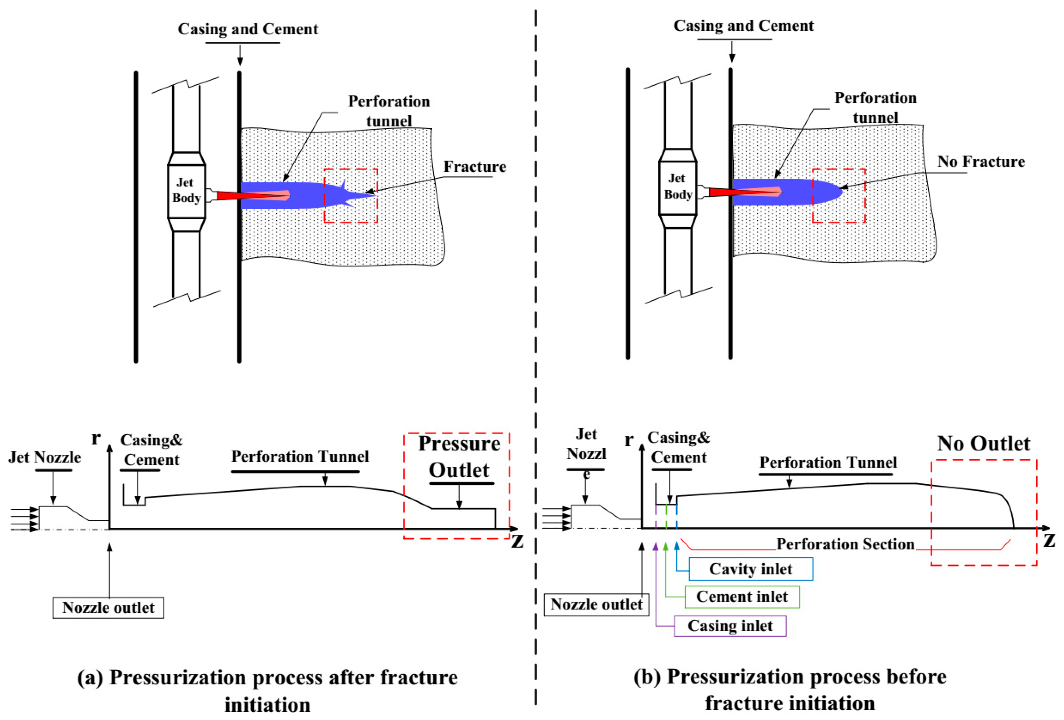
Several SC-CO2 jet models were proposed in the past decades, most which paid attention to the free SC-CO2 jet in the free environment [14,22,23]. However, a free jet is different from a SC-CO2 jet in a limited perforation tunnel. A typical hydro-fracturing process of a shale gas well in Sichuan is shown in Figure 1. As we all know, macro-fractures are created by a sufficiently high-pressure fracturing fluid. Hence, in the whole hydro-fracturing process there should be a process to create fractures around perforations. Based on the fracture generation or not, the whole process can be artificially divided into two stages: Stage I, where sand and fracture fluid are pressurized in the perforation tunnel with increasing tubing pressure and without any fracture propagation; and Stage II, where sand and fracture fluid invade the reservoir with a sharp drop of the tubing pressure and fracture propagation. When studying Stage II, the model of the perforation tunnel is open to the reservoir which is the outlet boundary for the simulation model [17]. In Stage I there was no micro-crack initiation in the limited perforation, consequently resulting in different pressurization processes of the SC-CO2 jet. Thus, the numerical model and boundary should be different from the case of fracture initiation.

2.2. Numerical Model and CO2 Physical Characteristic

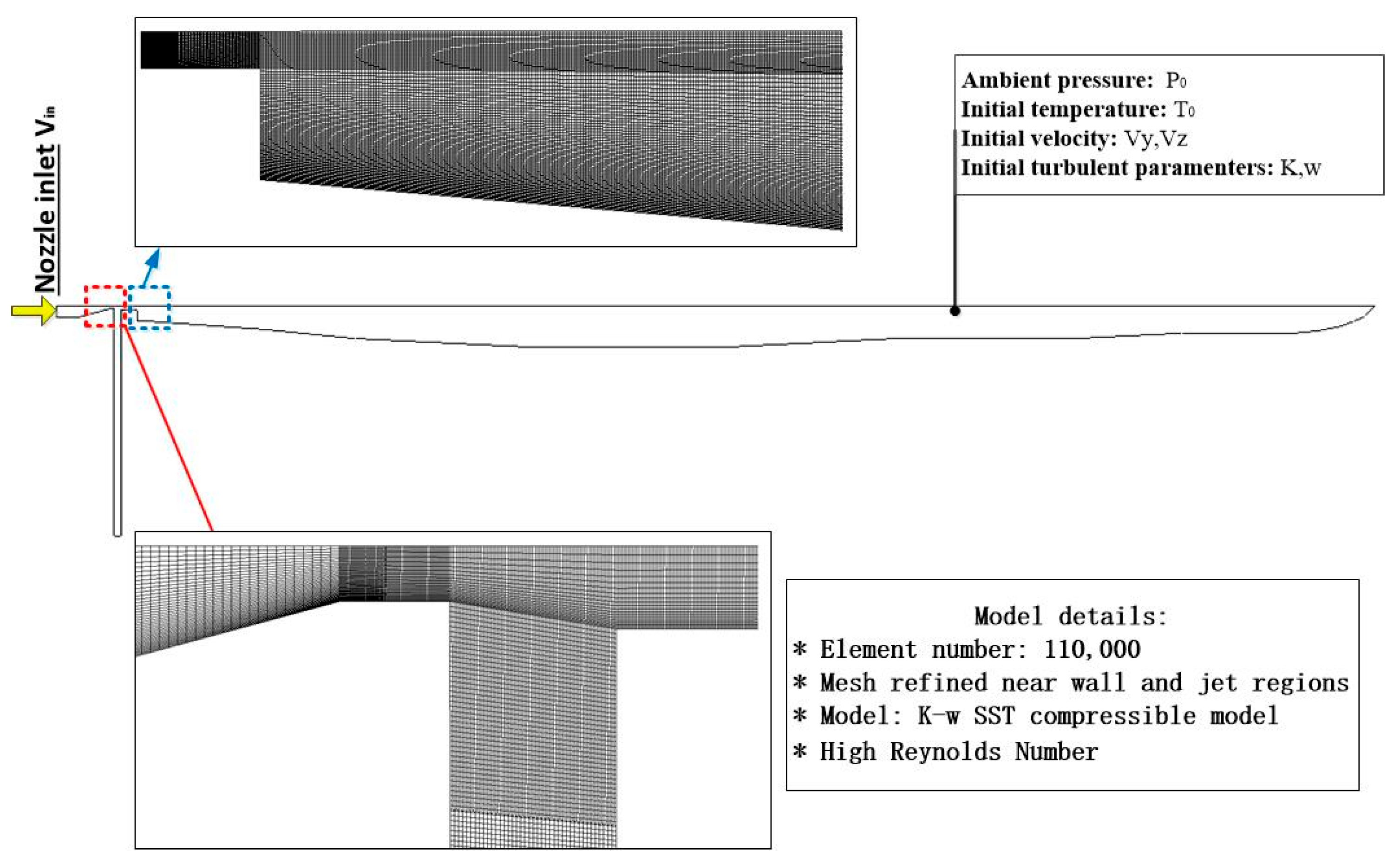
Jet fracturing is a complicated process, especially for SC-CO2 jets in a perforation tunnel. Previous studies have not distinguished the difference between the two models of SC-CO2 jets in a perforation tunnel. The comparison has indicated that there are different boundaries when studying this problem (see Figure 2). Before fracture initiation, the SC-CO2 in the perforation tunnel is compressed continuously, resulting in a pressure boost and an extreme variation of the density, temperature and other turbulence-related parameters. To accurately simulate the boosting of the SC-CO2 jet, the mesh density is improved close to the wall surface of the perforation (see Figure 3). A SST k-w turbulent model was used to get the turbulent change in the perforation. Different from the previous studies, this numerical model has no outlet boundary in the perforation, which makes it more difficult to converge while simulating the SC-CO2 jet fracturing. Several assumptions are considered for this model: (1) there was no phase change of SC-CO2 and (2) there was no fracture propagation during the process of the hydro-fracture jet procedure.
The SC-CO2 jet penetrates into the perforation with a significant variation of temperature, pressure and velocity. The numerical model consists of mass equations, momentum equations and energy equations, which consider heat transfer and a compressible fluid. The conservative, two-dimensional plane flow, inviscid flow equations are as follows:
{ ρ t + ρ V = 0 ρ u t + ( ρ u V ) = p y + τ y y y + τ z y z + ρ f y ρ v t + ( ρ u V ) = p z + τ y z y + τ z z z + ρ f z
t [ ρ ( e + V 2 2 ) ] + [ ρ ( e + V 2 2 ) V ] + ρ q ˙ + y ( k T y ) + z ( k T z ) = ( u ρ ) y ( v ρ ) z + ( u τ y y ) y + ( u τ z y ) z + ( v τ y z ) y + ( v τ z z ) z + ρ f V
It is shown that the Shear Stress Transport (SST) k-ω model [24,25] is more accurate and appropriate for turbulent simulations, especially for the jet mixing layer. The higher Reynolds k-ω turbulence model was selected, and the parameters of k and ω are as follows, respectively:
k = 3 2 ( τ ¯ v ¯ ) 2
ω = k 1 / 2 / ( 0.27 L ¯ )
where i ¯   ( = 0.01 0.1 ) is the turbulence intensity.
The Peng-Robison (PR) equation of state (EOS) [26] was widely used in the supercritical fluid simulation and successfully simulated in the SC-CO2 jet. It is expressed as follows:
P = R s p T V b a ( T ) V 2 + 2 V b b 2
and the above parameters can be calculated through the following formulas:
b = 0.0778 R s p T c p c
a 0 = 0.45724 R s p 2 T c 2 p c
a ( T ) = a 0 n
T r = T / T c
n = [ 1 + ( 0.37464 + 1.54226 ω 0 0.2699 ω 0 2 ) ( 1 T r 0.5 ) ] 2
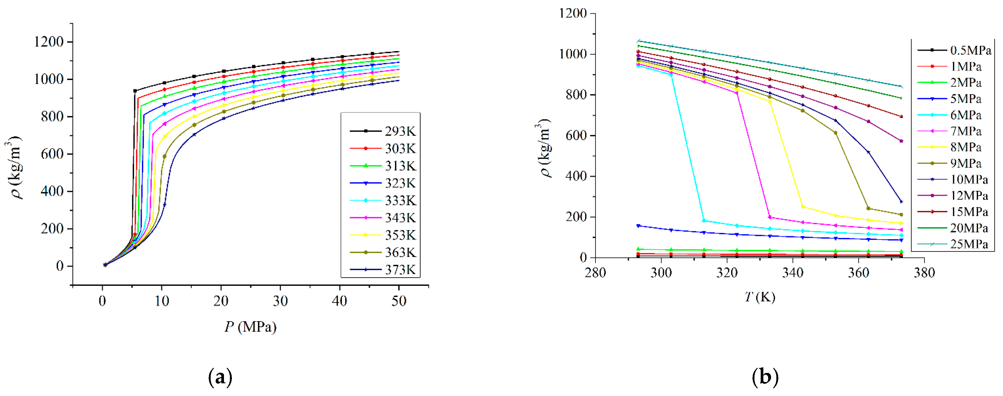
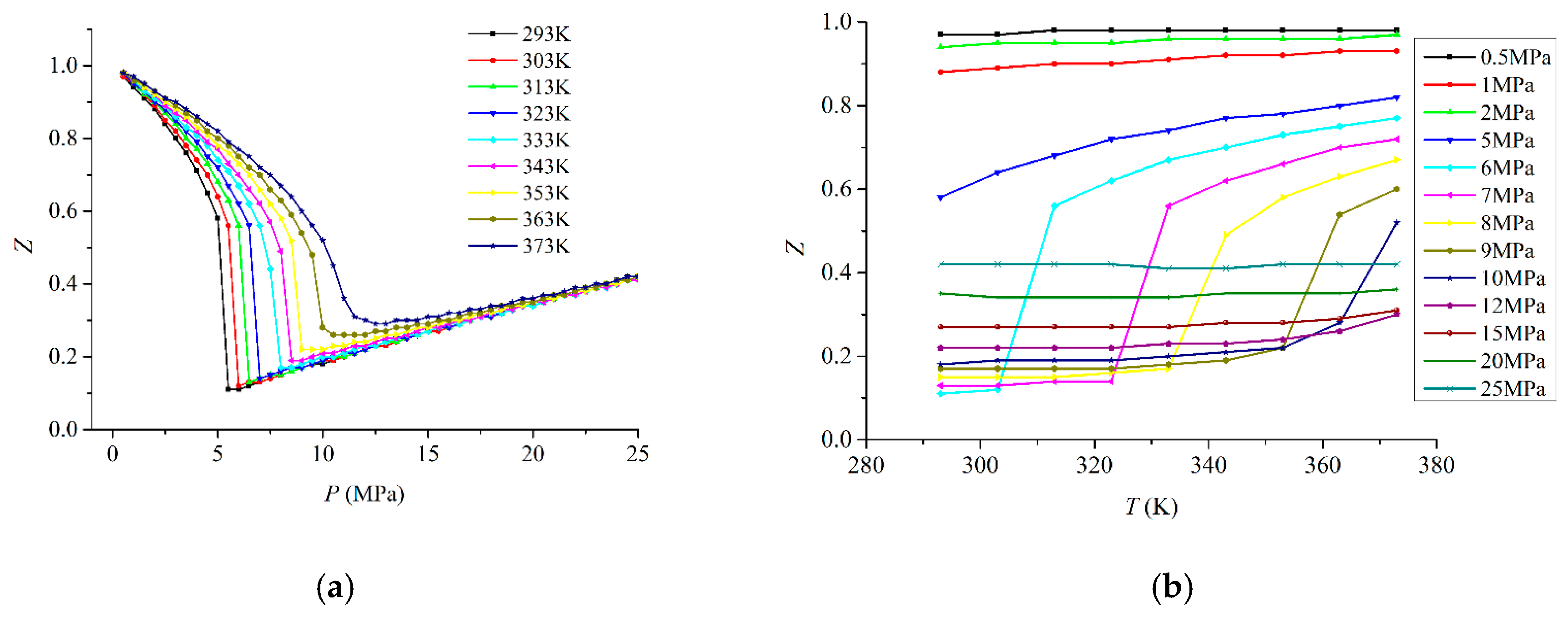
Different from the CO2 gas, SC-CO2 has unique physical characteristics, especially the density, viscosity, compressibility coefficient and so on. According to the PR EOS, the variation of physical characteristics can be calculated by using Fortran Codes (see Figure 4, Figure 5 and Figure 6). It can be seen that the density increases sharply with the growth of pressure before 7.38 MPa (see Figure 4a) and the density of CO2 decreases smoothly with the increase of temperature (see Figure 4b). However, a significant change occurs while the pressure and temperature are varied from 7.35 to 7.40 MPa and 30 to 32 °C, respectively. The dramatic variation illustrates that it is difficult to accurately simulate the density of CO2 close to the critical point.
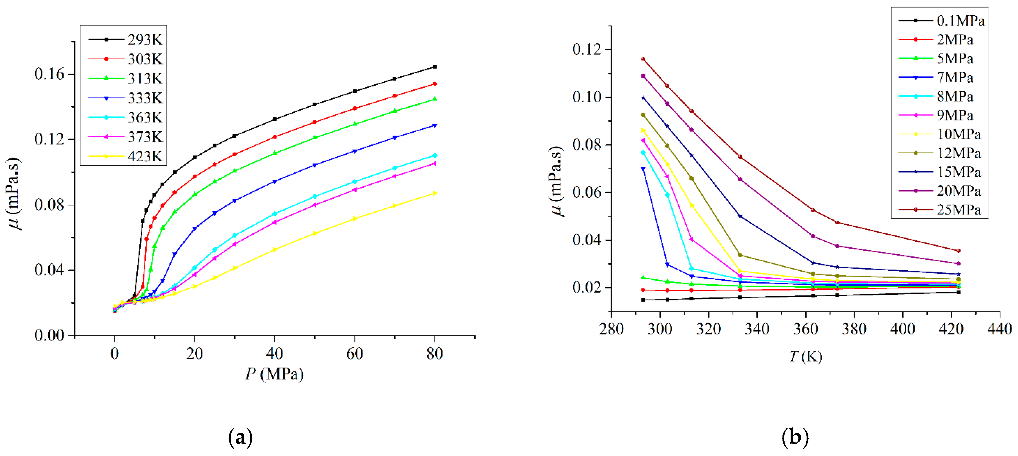
Similarly, the viscosity of CO2 rises with the increase of pressure and drops with the increase of temperature (see Figure 5). There is also abrupt change when the pressure and temperature of CO2 are close to the critical point (7.38 MPa, 31.4 °C). However, if the pressure is extremely large, the influence of temperature is slight according to Figure 5b.

3. Results

3.1. Verification of Numerical Results

To verify the simulation results, the present model was used to simulate the experimental case (see Figure 7). The jet inlet pressure was set at 15 MPa, and ambient pressure was set at 10 MPa with the same parameters of nozzle and perforation structure. The length-to-nozzle diameter ratio is 2 with the contraction angle of 30.5°. There is no outlet at the tip of the perforation tunnel, which is different from the previous numerical model [17].
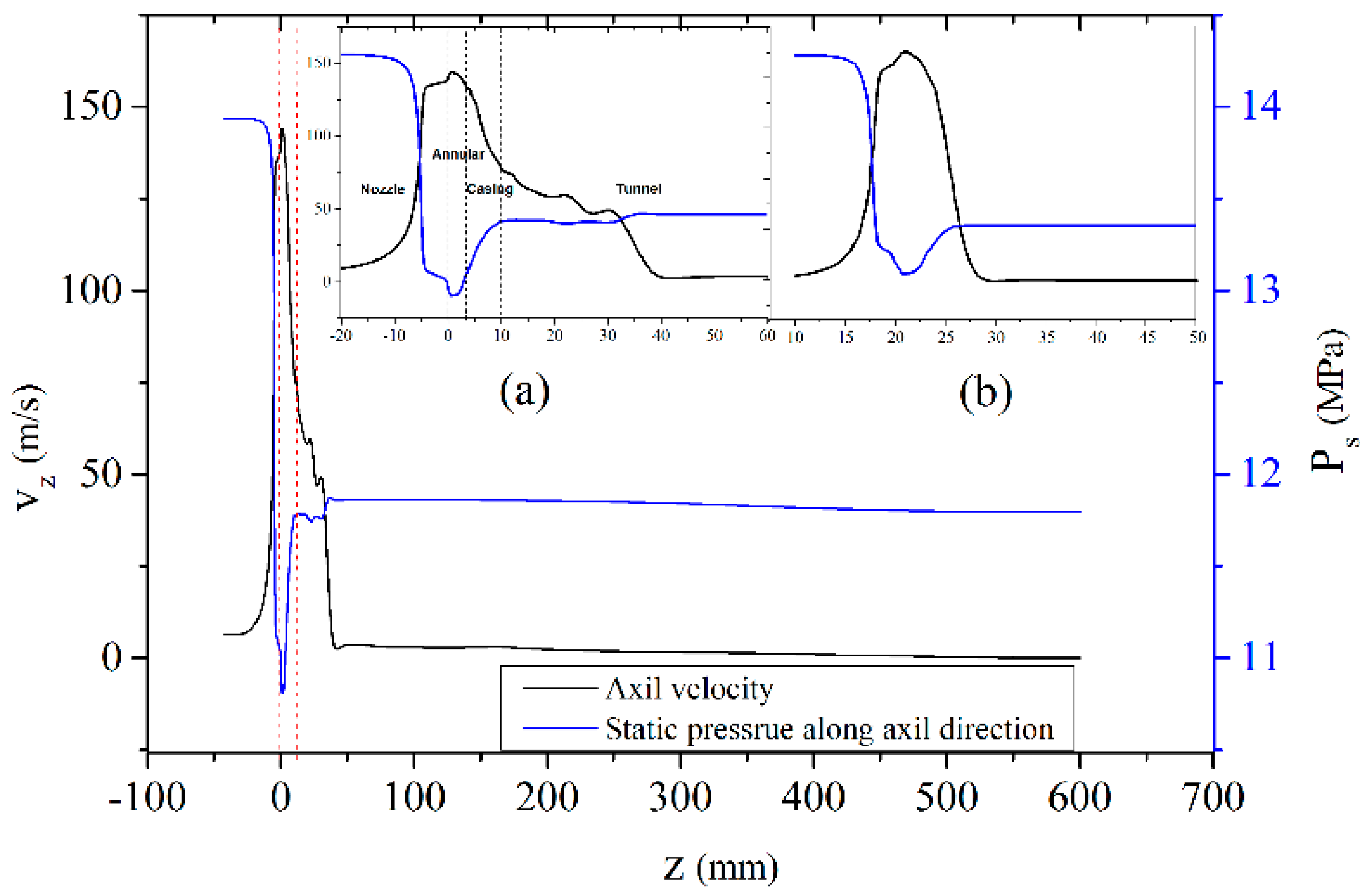
The primary task is to study the distribution of static pressure and velocity along the axis direction of the perforation. As shown in Figure 7, there is a similar variation of the statistic pressure and velocity in the perforation like reported in He’s results [17]. When high-pressure SC-CO2 fluid passes through the nozzle section, the static pressure gradually decreases and fluid velocity increases significantly, because some of the static pressure starts to convert into kinetic pressure. After SC-CO2 flows though the annular section and jet into the perforation, the static pressure increases from the minimum value to the extreme value, while the velocity decreases sharply. Compared our results (see Figure 7a) with He’s results (see Figure 7b), the declining trend of axial velocity appears more slight. Ultimately, when the SC-CO2 jet comes to a standstill, the axial velocity becomes zero and the statistic pressure increases to the boosting pressure. As shown in Figure 7a, it can be seen that axial velocity slowly decreases to 0 m/s when z is 40 mm, while in He’s result the axial velocity steeply dropped to 0 m/s as z equaled 10 mm. Additionally, the fact of the unstable decrease of axial velocity in the perforation indicates that the jet core is discontinued, which is the reason leading to a longer length of the jet core.
For further study the verification and validation of the numerical model, a comparison of three different jet inlet pressures, which are 15, 20 and 25 MPa, respectively, was conducted (Table 1). The comparison demonstrates that the stagnation pressure of the numerical simulation is close to the experimental results under a similar pressure difference. Therefore, it is valid to apply the numerical model to study SC-CO2 jet fracturing.

3.2. The Pressurization in Limited Perforation

According to the fluid mechanic, the total pressure is defined as follows:
P t = P s + P v
where P v = 1 2 ρ v 2 .
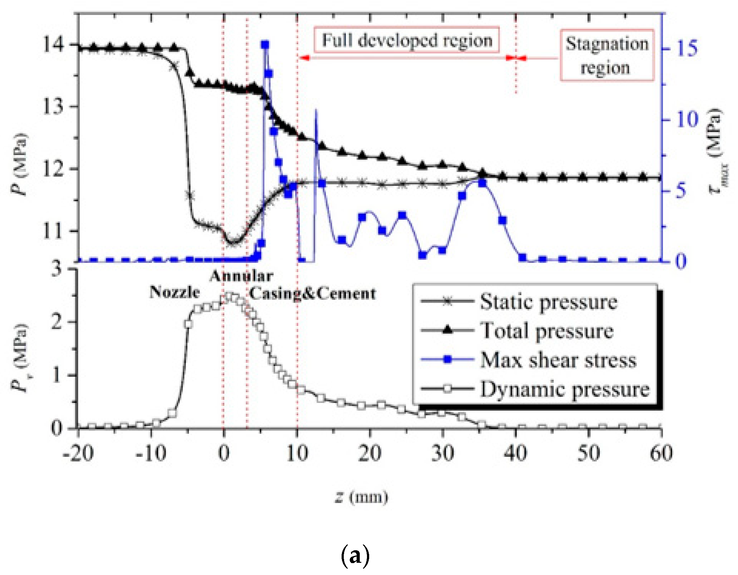
As shown in Figure 8a, there are two total pressure drops in the nozzle convergent section and the casing and cement section. This means that the total energy of the SC-CO2 jet undergoes two losses in the above two sections. Meanwhile, the dynamic pressure in the nozzle convergent section dramatically increases to the peak value of 2.5 MPa. Then the SC-CO2 jet passes though the annular section with a little rise in the dynamic pressure and follows a sharp decline in the casing and cement section. After the SC-CO2 jet penetrates into the perforation, it shows a steady decline until it ultimately decreases to 0 MPa. We looked at the variation of max shear stress in the fully developed region and observed a dramatic fluctuation between 1 MPa and 11 MPa, which implies strong turbulent mixing in the fully developed region.
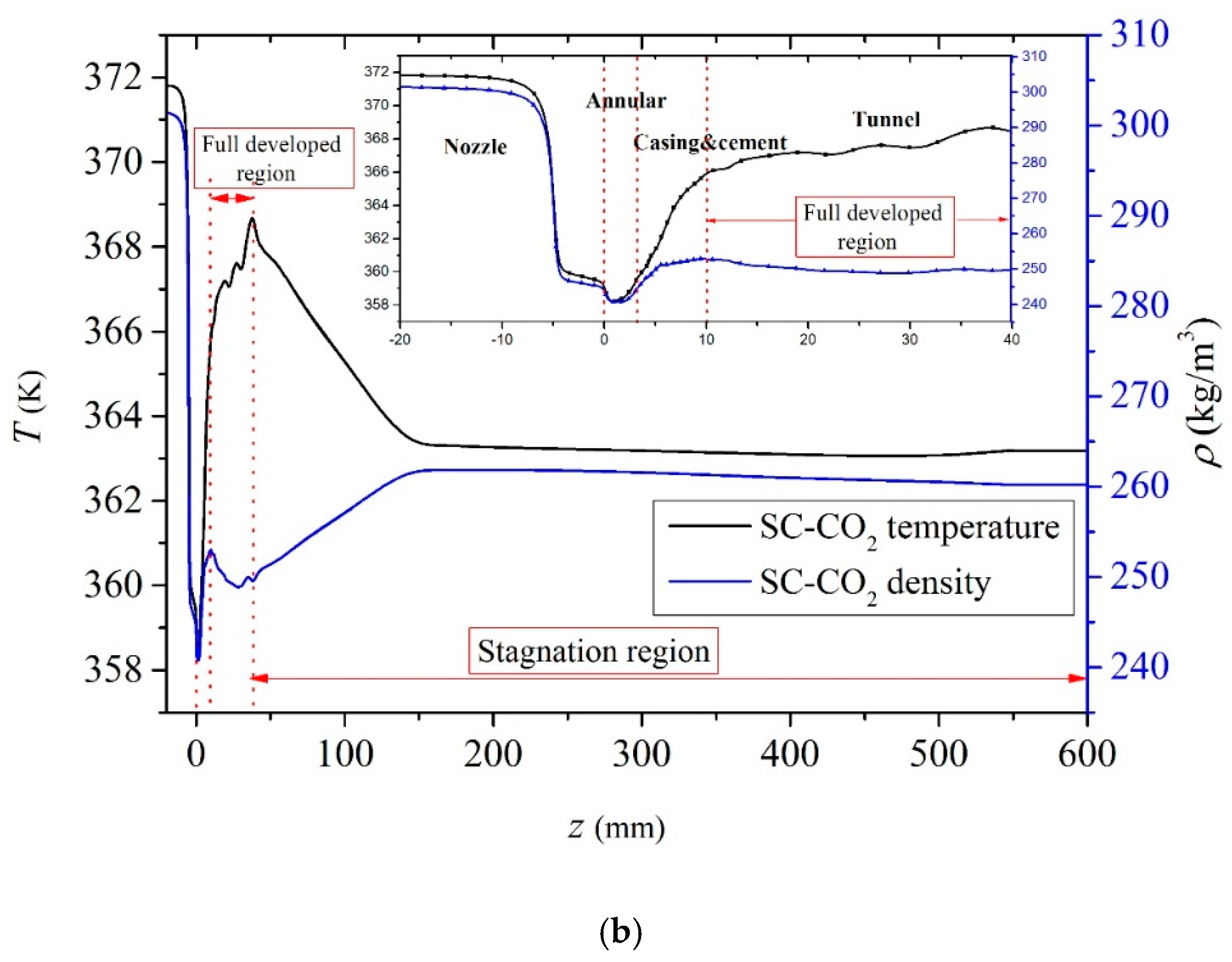
There is a significant different variation of the density and temperature between a water jet and a SC-CO2 jet. As shown in Figure 8b, in the nozzle section, both the temperature and density drop sharply with a similar trend to the minimum value in the annular section. With the increasing axial distance, the temperature of the SC-CO2 jet steadily rises to the peak value, but the density falls slightly. The reason is that a part of thermodynamic energy is converted into dynamic energy in the nozzle convergent section. However, in the casing and cement section, some part of the dynamic pressure is converted into thermodynamic energy due to the increasing temperature and density. On the wall surface of the perforation, the increasing density and static pressure are more beneficial for fracture initiation.

3.3. The Velocity Distribution in Limited Perforation

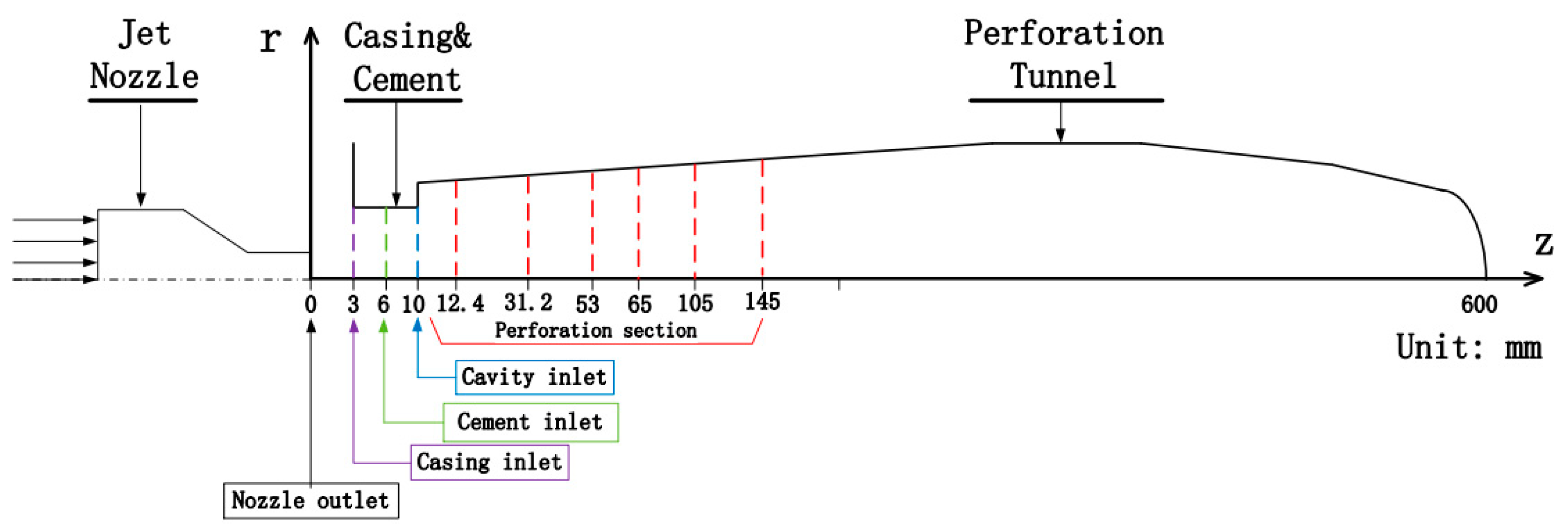
In past studies, the velocity along the axial direction attracted more attention when studying SC-CO2 jet fracturing [16,17], and the velocity distribution of SC-CO2 along the radial direction was mostly ignored by researchers. Actually, when the SC-CO2 jet passes through the nozzle and penetrates into the perforation, there is a strong interaction between the turbulent mixing-layer of the SC-CO2 jet and the perforation wall surface. In order to explore the radial velocity distribution of SC-CO2 jet, ten sections along the jet core direction were studied with different z values ranging from 0 to 145 mm, including the development region, full developed region and stagnation region. As shown in Figure 9, the ten sections are, respectively, the nozzle outlet cross-section (z = 0 mm), casing inlet cross-section (z = 3 mm), cement inlet cross-section (6 mm), perforation tunnel inlet cross-section (10 mm), and the perforation section (z = 12.4, 31.2, 53, 65, 105 and 145 mm).
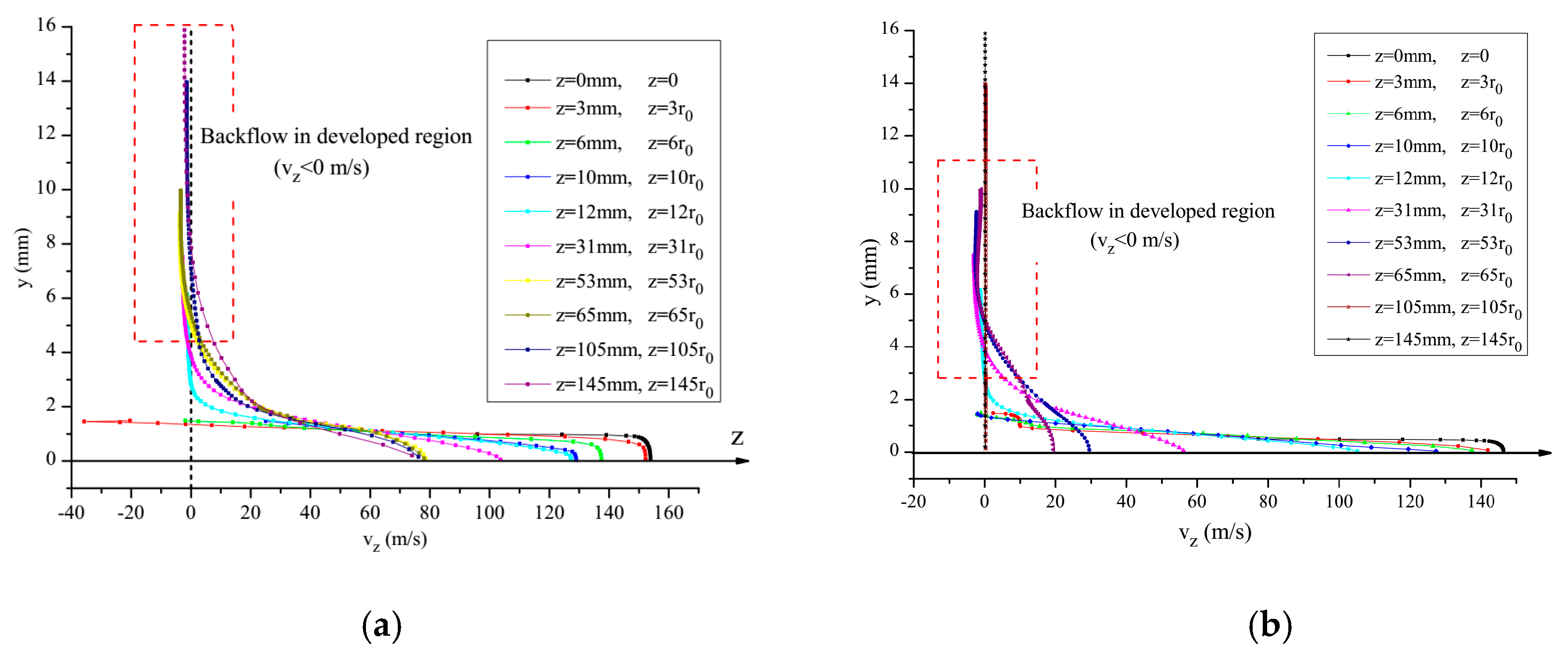
The velocity distributions of the ten different cross-sections along the radial direction of the jet core are compared in Figure 10. The max velocity in the radial direction drops dramatically with increasing z because of the large conversion of fluid kinetic energy into static and thermodynamic energy. With the reduction of y, it is observed that the axial directional velocity (vz) on the perforation wall surface is less than 0 m/s. The minimum velocity at the casing inlet and cement inlet is also definitely below 0 m/s, which indicates that there is obvious backflow in the casing inlet section resulting in extreme shear mixing of the SC-CO2. Hence, an annular “hydraulic isolating ring” happens and this prevents annular dirty fluid from flowing toward the existing fractures. In the perforation section, when the z rises from 10 times r0 to 145 times r0, the axial velocity on the perforation wall surface would decrease below 0 m/s, resulting in backflow. It is the reason why the perforation radius is larger than the casing inlet radius after the SC-CO2 jet perforating [26].
Reducing the nozzle outlet length L0 from 2 to 1 mm (See Figure 11a,b), the peak value of axial velocity falls more sharply at the same z and y. While the axial distance is larger than 105 times of r0, the axial velocity starts reducing to 0m/s. Backflow also occurs when y exceeds 4 mm (see Figure 10b). It is indicated that the decline of nozzle outlet length decreases the length of the fully developed region of the jet core.
Based on the jet theory [27], the dimensionless axial velocity and length can be expressed as follows:
ϕ = v / v m ,   η = r / b ,   γ = r / r max
The above b represents a typical value of r where v is equal to half the maximum velocity, bm represents the radius of perforation tunnel cross-section (rm), written as follows:
f ( b ) = 1 2 v m
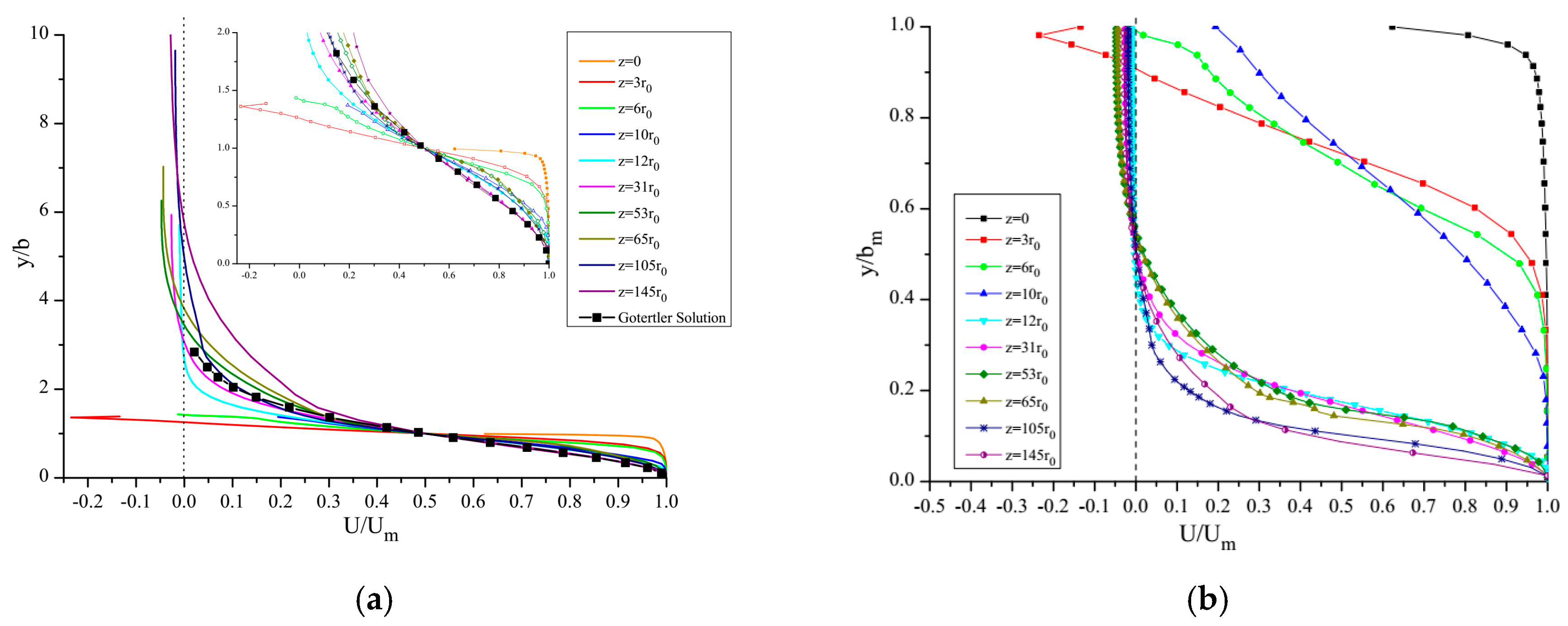
In Figure 11a, When η ≦ 1, the axial dimensionless velocity of the jet is the same as the mathematical results of the Goertler solution [27]; when η > 1, the distribution of axial dimensionless velocity is not different from the Goertler solution. The axial dimensionless velocity calculated by using the numerical method and Goertler solution are compared as shown in Figure 11. The distribution of axial dimensionless velocity does not conform to the traditional jet theory when the SC-CO2 jet enters the annular and casing and cement regions. The results indicate the traditional jet theory is not available for calculating SC-CO2 jet behavior.

4. Discussion

In this paper, the discussion of the turbulent flow field gives a new perspective for the SC-CO2 jet in the perforation tunnel based on jet theory [15,28,29]. Then the factors which affect the jet flow field and perforation tunnel pressurization, are analyzed in depth. To discuss the influence factors, Table 2 shows the numerical simulation scheme. The basic case is defined as follows: pressure difference is 10 MPa, jet inlet pressure is 20 MPa, ambient pressure is 10 MPa, nozzle outlet length is 2 mm, nozzle outlet radius is 1 mm, nozzle-to-casing inlet radius ratio (aperture ratio) is 2/3, SOE is Peng-Robinson, and fluid is SC-CO2.

4.1. The Effect of Nozzle Outlet Length

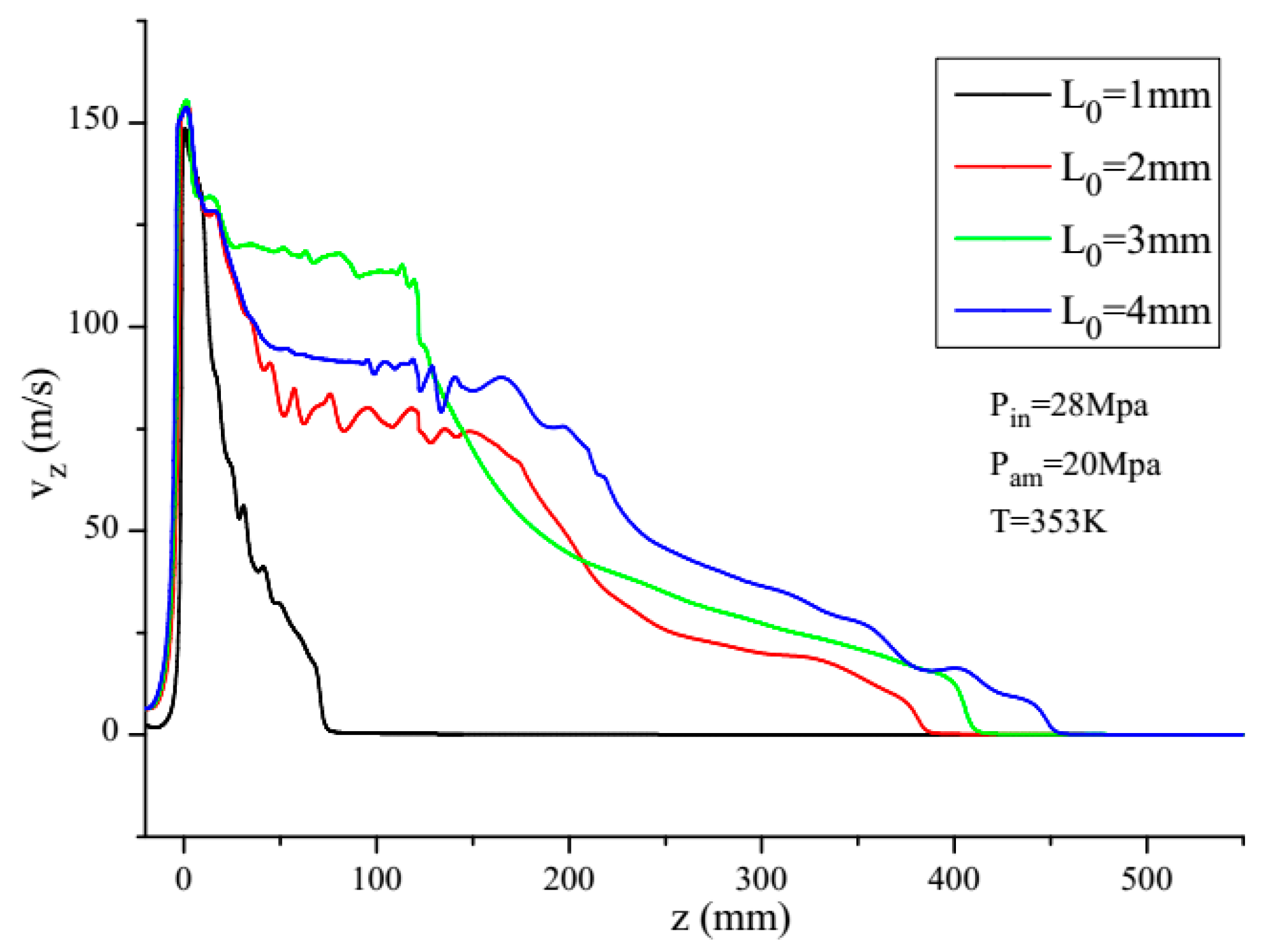
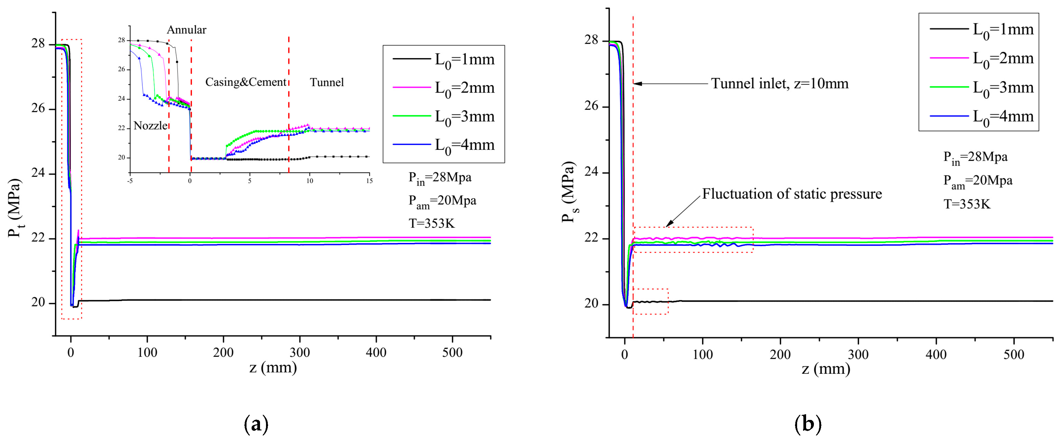
Many studies have demonstrated the length and diameter of the nozzle were the key influencing factors for jet fracturing [15,30]. However, the influence of the nozzle outlet length on the total pressure and velocity in limited perforation is still unclear. As Figure 12 shows, even when the length of the nozzle outlet increases from 1 to 4 mm with the same nozzle outlet diameter (2 mm), the maximum axial velocity is approximately the same. After a SC-CO2 jet passes through the nozzle outlet, the axial velocity of the jet drops more sharply than in other cases when the length of the nozzle outlet is 1 mm. This means that the shorter of the nozzle outlet is, the more steep the axial velocity drop obtained is. Therefore, it is recommended to increase the nozzle outlet to make sure we a SC-CO2 jet boost in the perforation with enough kinetic energy.
The total pressure on the perforation wall surface which determines the fracturing initiation is of great importance in SC-CO2 jet fracturing. As shown in Figure 13a, when the SC-CO2 jet is pressurized in the perforation tunnel, the shortest outlet length (L0 = 1 mm) obtains the lowest boosting pressure and when the nozzle length is 2 mm, there is the highest total pressure on the perforation surface. However, with L0 varying from 2 to 4 mm, the pressure in the perforation only rises slightly. It is clearly indicated that the short length of the nozzle outlet has a negative effect on the perforation pressurization. In addition, the distribution of static pressure (see Figure 13b), demonstrates that the generation of boosting pressure shows a fluctuating trend in the front section of perforation. It is believed that this static pressure fluctuation is attributable to the turbulent mixing in the fully developed region.

4.2. The Effect of Nozzle Outlet Radius

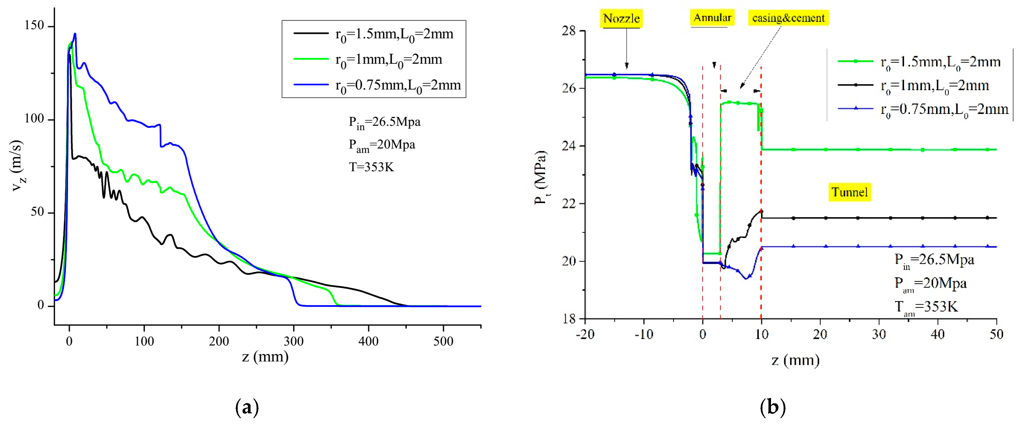
The nozzle outlet radius plays an important role in the jetting flow field and perforation pressurization. In He’s results [17], the perforation pressurization is discussed when the radius of the nozzle outlet only ranges from 0.7 to 1.3 mm, and the comparison of axial velocity is not studied for different nozzle outlet radii. As shown in Figure 14a, when the radius of the nozzle outlet is reduced, a higher axial velocity is observed in the perforation section. With the increasing axial distance (z), the axial velocity of the r0 = 1.5 mm group rapidly reduces in the both annular section and the casing and cement section, which indicates a fast loss of the kinetic energy of the SC-CO2 jet.
Obviously, and different from He’s results, the total pressure is slowly reduced to a stable value with increasing z. As the radius of the nozzle outlet increases from 0.75 to 1.5 mm, the boosting pressure in the perforation sharply decreases with increasing z coordination, and finally then remains steady in the whole annular section (see Figure 14b). However, it can be seen that the total pressure on the perforation wall surface sharply rises to its peak value in the casing and cement section (25.5 MPa) and then remains steady when the nozzle outlet radius is 1.5 mm. Comparing with the case of r0 = 1.5 mm, when the nozzle outlet radius is 1 mm, the maximum total pressure is only 21.7 MPa. Therefore, we can conclude that a larger nozzle outlet radius can achieve a higher boosting pressure. It also shows that a smaller radius makes a great contribution to the generation of a “hydraulic-fracturing ring” in the perforation tunnel.

4.3. The Effect of Aperture Ratio

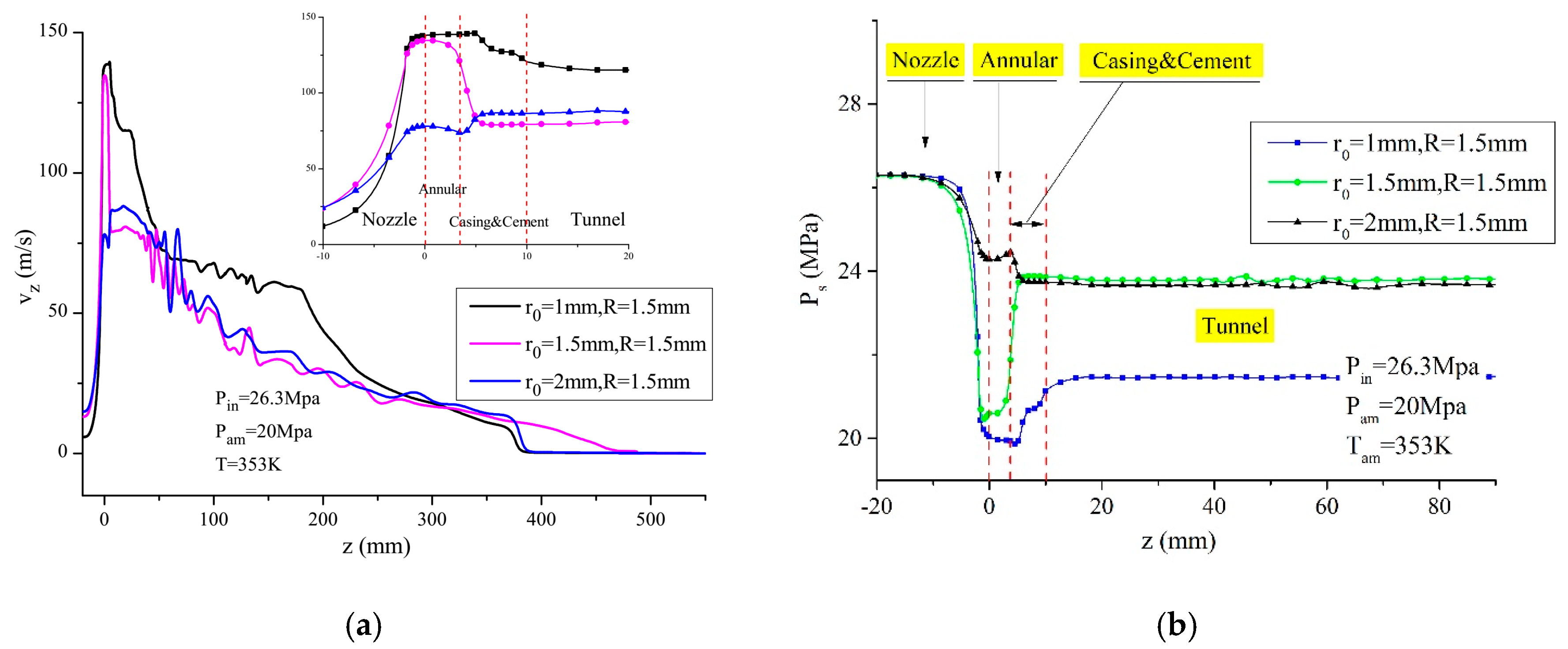
Unlike the SC-CO2 free jet, the SC-CO2 jet pressurization is affected by the interaction between jet flow and the casing and cement region. Like in the above discussion, there is strong shear mixing in the perforation tunnel, so the relationship between the nozzle outlet radius and the inlet radius of casing affects the SC-CO2 jet fracturing result. In previous SC-CO2 jet fracturing studies, this relationship is ignored. Three cases with aperture ratios (r0/R) of 2/3, 1, 4/3, respectively, are studied to explore the influence of the relationship. As Figure 15a showed, the peak value of axial velocity drops from 138.7 to 78 m/s when the nozzle outlet radius changes from 1 to 1.5 mm. It is demonstrated that when the aperture ratio is larger than 1, the maximum axial velocity is significantly reduced. In the casing and cement section, the axial velocity grows slightly when the aperture ratio is 4/3. However, while the aperture ratio is equal to 1, the axial velocity falls significantly to 41%, while an aperture ratio value of 2/3 the axial velocity steadily decreases from 138.7 to 120.7 m/s. This means that the larger the aperture ratio is, the lower the axial velocity is, which consequently affects the kinetic energy transformation in the perforation.
In addition, the “hydraulic isolating ring” starts disappearing while the nozzle outlet diameter is larger than the inlet radius of the casing section (see Figure 15b), as the static pressure of the annular is larger than the radius of the casing section. When the aperture ratio is less than 1, the max axial velocity is slightly higher than others and the boosting pressure obviously reduces. It is necessary to maximize the aperture ratio as much as possible to ensure pressurization as large as possible but not exceeding 1.

4.4. The Similar Experiments of SC-CO2 Jet Flowing

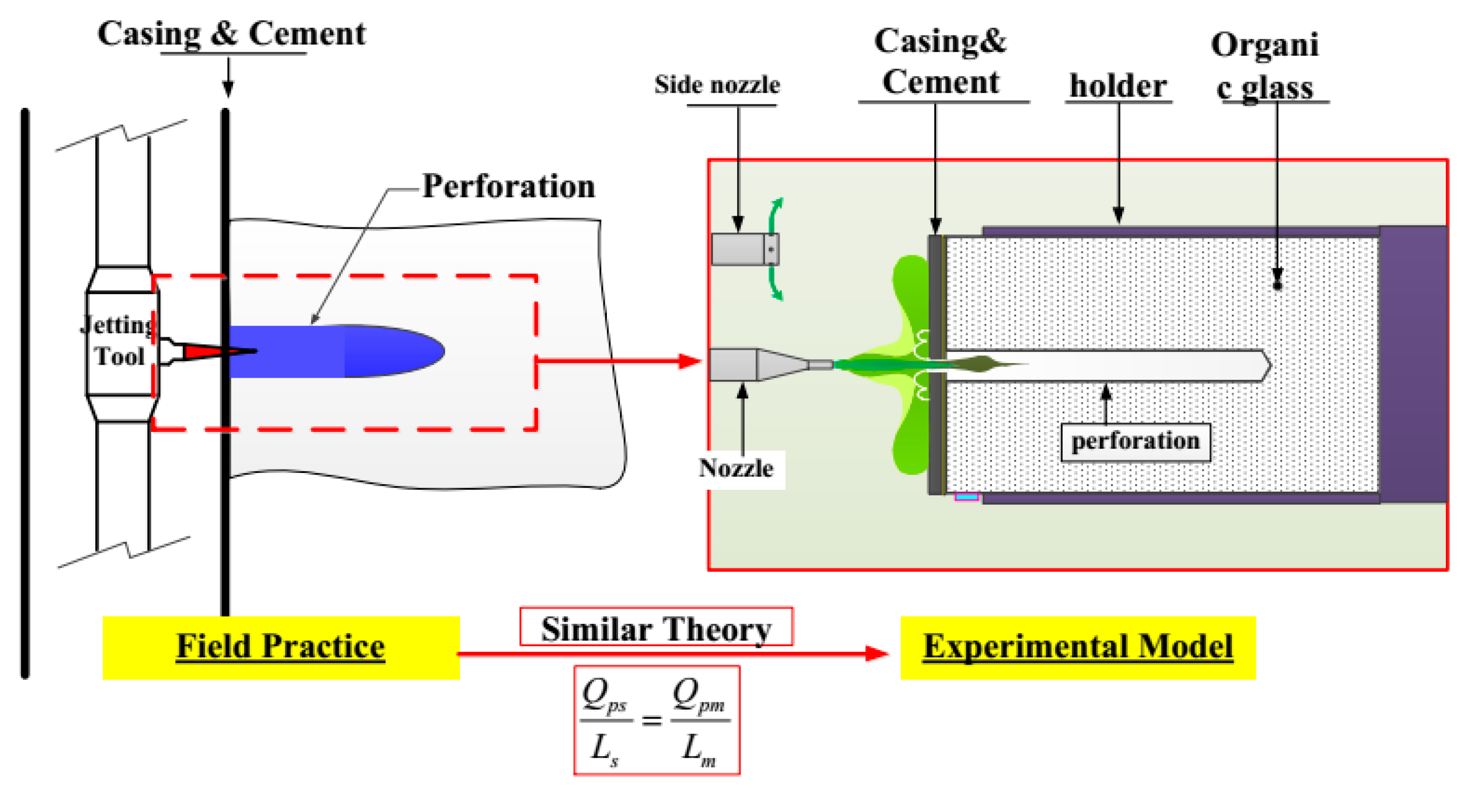
To make sure of the dynamic similarity between the field practice and our experimental model (see Figure 16) the Reynolds number similarity criterion is applied for our SC-CO2 jet fracturing experiments. The Reynolds number is a special case of equal Newton number, representing the ratio between inertial force and viscous force. Therefore, a similar viscous force can be obtained in these experiments according to the similarity theory. The internal friction of the CO2 jetting caused by the viscous force can be expressed as:
T f = μ A d u d y
Thus, the dimensionless form of the above formula can be expressed as:
[ T f ] = [ μ ] [ L 2 ] [ v L ] = μ L v
The dimensionless form of inertial force is [ F ] = ρ L 2 v and because the Reynolds Number is similar, we have:
Re s = Re m
Then the similar Reynolds numbers of the experimental model and the field model can be expressed as, respectively:
μ s L s v s ρ s L s 2 v s 2 = μ m L m v m ρ m L m 2 v m 2
In the above formula, the subscript s indicates the experimental model parameters, and the subscript m indicates the field model parameters. After simplification, Equation (18) can be expressed as:
L s v s υ s = L m v m υ m
Hence, for the SC-CO2 jet fracturing in a limited perforation scenario, the flow and perforation length have a similar relationship expressed as follows:
Q p s L s = Q p m L m
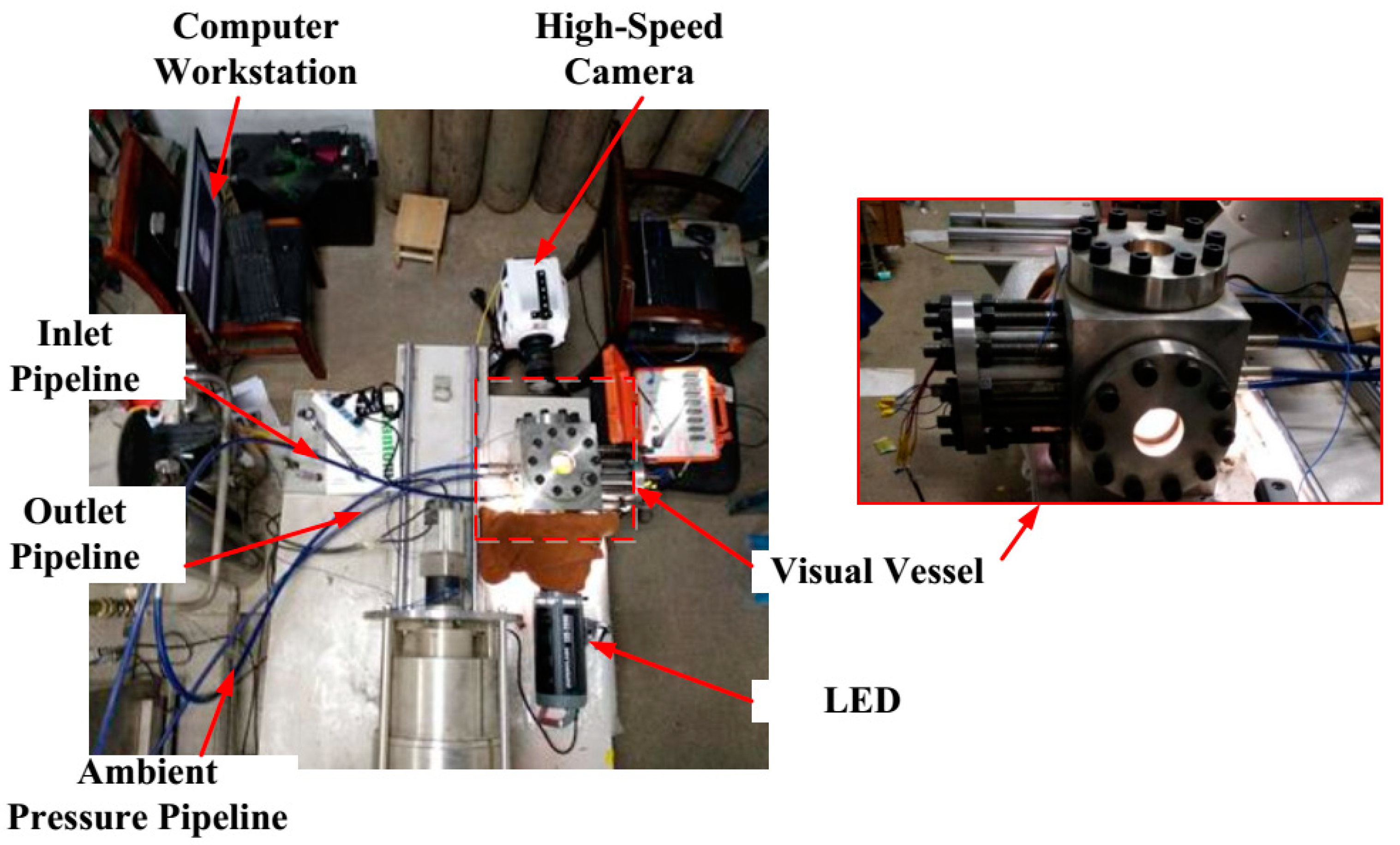
According to the operation parameters of field practice, the experimental parameters can be designed by using the above similarity theory and a method reported before [31]. As shown in Figure 17, SC-CO2 jet fracturing experiments were conducted with a high-speed camera (HSC). Before SC-CO2 jet fracturing, the ambient pressure and temperature in the visualized vessel are pre-prepared via injecting CO2 and heating the vessel. Then the pressure of the buffer tank should be pressurized to the jet pressure design value. Then, the flow field of SC-CO2 jet fracturing is captured by the HSC.
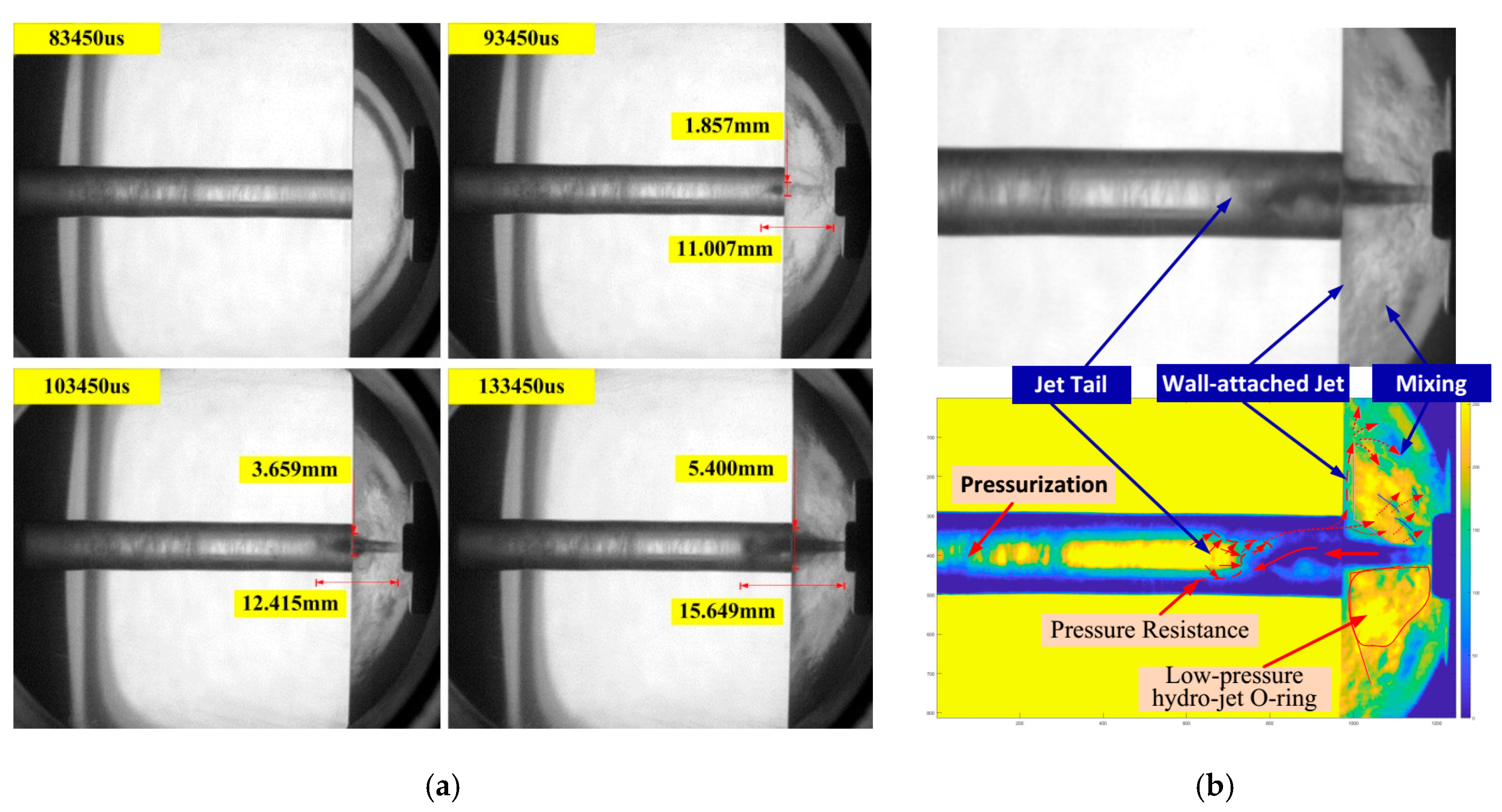
According to the captured high-speed photography (HSP) images (see Figure 18a), the jet width is smaller than the diameter of the perforation at 83450 μs. With the continuously jetting of CO2, there is an unobvious backflow in the perforation tunnel from the images. After 0.01 s jetting (at 93450 μs), the jet length gradually increases with the increasing jet pressure. Meanwhile, it can be seen that the jet tail of the SC-CO2 jet starts penetrating into the perforation. Consequently, the perforation pressure increases quickly as in the simulation results. However, the jet width is still smaller than the perforation diameter. With the increase in time from 10345 μs to 133450 μs, it is found that the jet length varies from 12.415 to 15.649 mm, and the jet width also rises from 3.659 to 5.4 mm in only 0.05 s. Then the jet flow field maintains a stable structure with the maximum jet length and jet width. When the high velocity jetting was captured by the HSP, the images obtained are grey-scale images, in which the black color represents the high-density CO2 due to the fact less light passes through the CO2 jet. Accordingly, the white color represents the low-density CO2 due to the fact more light can pass through the CO2 jet. Hence, in order to clearly distinguish between the jet and the environment, two different density CO2 values are drawn in yellow and blue, respectively, by using the Digital Image Processing method. In Figure 18, the blue color means high-density CO2 and the yellow color means low density CO2. Looking forward to the stable flow structure shown in Figure 18b, it is clear that the expanded jet core is divided into two parts after exiting the nozzle, according to the HSP images and digital images. The majority of SC-CO2 jet flows into the perforation and pressurizes the perforation with a wobbly jet tail. Consequently, some high-pressure CO2 escapes from the annular region between the jet core and the perforation surface because of the existence of the high-pressure CO2 in the limited perforation tunnel. Some parts of the SC-CO2 jet expand and flow attached on the specimen surface, forming a wall-attached jet. Due to the existence of high-velocity jet core, the pressure of the annular region around the jet core drops, resulting in the low-pressure hydro-jet O-ring which was reported by Huang et al. and Sheng et al. [9,32]. As a result, the strong mixing of CO2 in the annular region and the CO2 jet is also monitored by using HSP in Figure 18b, which is in accord with the numerical results. Combining with the above simulation results, it is concluded that there is a turbulent flow field of SC-CO2 in the limited perforation and a low-pressure hydro-jet O-ring around the jet core. The development of a SC-CO2 jet in the limited perforation clearly illustrates the complex flow characteristics of SC-CO2 jets during jet fracturing, which are affected by the nozzle scale.

5. Conclusions

This study explored the flow field of a SC-CO2 jet in a limited perforation before fracture initiation. The numerical simulation results were verified by experiments. The pressurization, velocity distribution of SC-CO2 and the influencing factors are studied using a numerical simulation model. We also discuss the flow characteristics of SC-CO2 jets via High-Speed Photography based on similarity theory. The following conclusions are reached:
(1)
In the fully developed region of the SC-CO2 jet, the max shear stress dramatically fluctuates between 1 MPa and 11 MPa during SC-CO2 jet boosting, which means strongly turbulent mixing occurs in the fully developed region. On the perforation wall surface, the axial velocity reduces to even less than 0 m/s, resulting in a backflow in the perforation tunnel.
(2)
The structure of the nozzle outlet distinctly affects the pressurization of the SC-CO2 jet. With the decreasing length of the nozzle outlet, the axial velocity drops more sharply in the annular and casing and cement sections. Moreover, when the diameter of the nozzle outlet increases, the axial velocity drops faster in the annular section and the boosting pressure becomes higher.
(3)
The aperture ratio between the nozzle outlet and casing perforation inlet significantly affects the jet flow field in SC-CO2 jet fracturing, resulting in the disappearance of the “hydraulic isolation ring” and a decrease of the boosting pressure.
(4)
Based on the similarity theory, High-Speed Photography results clearly show that the SC-CO2 develops into full jetting in only 0.07 s and there exists a strong mixing in the annular region between the jet core and the environment according to the numerical simulation.

Author Contributions

C.C., S.X. conceived and designed the schemes; C.C. and S.X. analyzed the data; Q.L., D.L. performed the experiments; B.L. contributed methodology; Y.K. contributed materials; C.C. wrote the original paper; Q.L. and S.X. participated the manuscript revising. All authors have read and agreed to the published version of the manuscript.

Funding

The authors express their appreciations to Scientific Research Starting Project of SWPU (No. 2019QHZ009), the National Key Basic Research Program of China (No. 2014CB239203), National Key Basic Research Program of China (No. 51504209, No. 51804268) and CNPC Key Program Funding (No. 19-ZC0609-0001) for their financial support of this work.

Conflicts of Interest

The authors declare no conflict of interest.

Nomenclature

x, y, zThird local coordinate, mm
rRadial direction coordinate, mm
C p Specific heat at constant pressure, kJ/kgK
C v Specific heat at constant volume, kJ/kgK
TTemperature, K
T c Critical temperature, K
tTime, s
μFluid viscosity, pa sa⋅s
ZCompressibility coefficient, -
ρ, ρ c Density and critical density, kg/ m 3
P , P c Pressure, critical pressure, MPa
P s , P d Static and dynamic pressure, MPa
P t Total pressure, MPa
P i n Nozzle inlet pressure, MPa
P a m Ambient pressure, MPa
T a m Ambient temperature, K
V c Critical specific volume, m 3 / kg
R s p Specific gas constant, -
kKinetic energy of turbulence, -
ωSpecific dissipation rate of turbulence, -
v z Axial velocity, m/s
vmaxMax axial velocity, m/s
τ m a x Max shear stress. MPa
b , a 0 Constants of PR equation, -
w Acentric factor, -
Vspecific Volume, m 3 / kg
nConstants of PR equation, -
dNozzle outlet diameter, mm
lNozzle outlet length, mm
r0Nozzle outlet radius, mm
rmaxMax radius of the perforation tunnel, mm
D c Inlet diameter of casing, mm
RRadius of casing tunnel cross-section, mm
R e Reynolds number, dimensionless
ϕDimensionless axial velocity, -
ηDimensionless radius, -
γDimensionless radius, -
TfInternal friction, N
μViscosity, Pa.s
Aarea, m2
FInertia force, N
ResReynolds number in experimental model, -
μsViscosity in experimental model, Pa.s
LsLength in experimental model, m
vsVelocity in experimental model, m/s
ρsDensity in experimental model, kg/m3
QpsFlow rate in experimental model, m3/s
RemReynolds number in field practice, -
μmViscosity in field practice, Pa.s
LmLength in field practice, m
vmVelocity in field practice, m/s
ρmDensity in field practice, kg/m3
QpmFlow rate field practice, m3/s

References

  1. Middleton, R.; Viswanathan, H.; Currier, R.; Gupta, R. CO2 as a fracturing fluid: Potential for commercial-scale shale gas production and CO2 sequestration. Energy Procedia 2014, 63, 7780–7784. [Google Scholar] [CrossRef] [Green Version]
  2. He, L.; Feng, W.; Zhang, J.; Siwei, M.; Yongwei, D. Fracturing with carbon dioxide: Application status and development trend. Pet. Explor. Dev. 2014, 41, 513–519. [Google Scholar]
  3. Middleton, R.S.; Carey, J.W.; Currier, R.P.; Hyman, J.D.; Kang, Q.; Karra, S.; Jiménez-Martínez, J.; Porter, M.L.; Viswanathan, H.S. Shale gas and non-aqueous fracturing fluids: Opportunities and challenges for supercritical CO2. Appl. Energy 2015, 147, 500–509. [Google Scholar] [CrossRef] [Green Version]
  4. Kolle, J.J. Coiled-tubing Drilling with Supercritical Carbon Dioxide, SPE 65534; Society of Petroleum Engineers: Richardson, TX, USA, 2000. [Google Scholar]
  5. Du, Y.K.; Wang, R.H.; Ni, H.J.; Li, M.K.; Song, W.Q.; Song, H.F. Determination of rock-breaking performance of high-pressure supercritical carbon dioxide jet. J. Hydrodyn. Ser. B 2012, 24, 554–560. [Google Scholar] [CrossRef]
  6. Kolle, J.J.; Marvin, M.H. Jet Assisted Drilling with Supercritical Carbon Dioxide; Tempress Technologies Inc.: Renton, WA, USA, 2000. [Google Scholar]
  7. Du, Y.K.; Wang, R.H.; Ni, H.J.; Huang, Z.Y.; Li, M.K. Dynamical analysis of high-pressure supercritical carbon dioxide jet in well drilling. J. Hydrodyn. Ser. B 2013, 25, 528–534. [Google Scholar] [CrossRef]
  8. Wang, H.; Li, G.; Shen, Z.; Tian, S.; Sun, B.; He, Z.; Lu, P. Experiment on rock breaking with supercritical carbon dioxide jet. J. Pet. Sci. Eng. 2015, 127, 305–310. [Google Scholar] [CrossRef]
  9. Sheng, M.; Li, G.; Huang, Z.; Tian, S.; Qu, H. Experimental study on hydraulic isolation mechanism during hydra-jet fracturing. Exp. Ther. Fluid Sci. 2013, 44, 722–726. [Google Scholar] [CrossRef]
  10. Fang, C.; Chen, W.; Amro, M. Simulation Study of Hydraulic Fracturing Using Super Critical CO2 in Shale. In Proceedings of the Abu Dhabi International Petroleum Exhibition and Conference, Society of Petroleum Engineers, Abu Dhabi, UAE, 10–13 November 2014. [Google Scholar]
  11. Kizaki, A.; Tanaka, H.; Ohashi, K.; Sakaguchi, K.; Matsuki, K. Hydraulic fracturing in Inada granite and Ogino tuff with super critical carbon dioxide. In Proceedings of the ISRM Regional Symposium-7th Asian Rock Mechanics Symposium, International Society for Rock Mechanics, Seoul, Korea, 15–19 October 2012. [Google Scholar]
  12. Khalil, I.; Miller, D.R. The structure of supercritical fluid free—jet expansions. AIChE J. 2004, 50, 2697–2704. [Google Scholar] [CrossRef]
  13. De Gregorio, F. Free compressible jet investigation. Exp. Fluids 2014, 55, 1693. [Google Scholar] [CrossRef]
  14. Liu, J.; Do-Quang, M.; Amberg, G. Numerical simulation of rapid expansion of supercritical carbon dioxide. AIChE J. 2015, 61, 317–332. [Google Scholar] [CrossRef]
  15. Wang, H.Z.; Li, G.S.; Tian, S.C.; Cheng, Y.X.; He, Z.G.; Yu, S.J. Flow field simulation of supercritical carbon dioxide jet: Comparison and sensitivity analysis. J. Hydrodyn. Ser. B 2015, 27, 210–215. [Google Scholar] [CrossRef]
  16. Wang, H.; Cheng, Y.; Li, G.; Shen, Z.; Tian, S.; Fan, X. Pressure boosting effect in perforation cavity during supercritical carbon dioxide jet fracturing. At. Sprays 2013, 23, 463–474. [Google Scholar]
  17. He, Z.; Tian, S.; Li, G.; Wang, H.; Shen, Z.; Xu, Z. The pressurization effect of jet fracturing using supercritical carbon dioxide. J. Nat. Gas Sci. Eng. 2015, 27, 842–851. [Google Scholar] [CrossRef]
  18. Yamamoto, S.; Furusawa, T.; Matsuzawa, R. Numerical simulation of supercritical carbon dioxide flows across critical point. Int. J. Heat Mass Transf. 2011, 54, 774–782. [Google Scholar] [CrossRef]
  19. Christen, W.; Rademann, K. Probing free jet expansions of supercritical fluids. Phys. Scr. 2009, 80, 048127. [Google Scholar] [CrossRef] [Green Version]
  20. Seebald, P.J. Turbulence in Transcritical CO2 Jets. Ph.D. Thesis, Purdue University, West Lafayette, IN, USA, August 2014. [Google Scholar]
  21. Liu, T. Shear-coaxial Injection and Mixing of Cryogenic Fluids under Supercritical Conditions. Ph.D. Thesis, The Pennsylvania State University, Pennsylvania, PA, USA, December 2007. [Google Scholar]
  22. Menter, F.R. Two-Equation Eddy-Viscosity Turbulence Models for Engineering Applications. AIAA J. 1994, 32, 1598–1605. [Google Scholar] [CrossRef] [Green Version]
  23. Peng, D.; Robinson, D.B. A New Two-Constant Equation of State. Ind. Eng. Chem. Fundam. 1976, 15, 59–64. [Google Scholar] [CrossRef]
  24. Hu, Y.; Liu, Y.; Cai, C.; Kang, Y.; Wang, X.; Huang, M.; Chen, F. Fracture initiation of an inhomogeneous shale rock under a pressurized supercritical CO2 jet. Appl. Sci. 2017, 7, 1093. [Google Scholar] [CrossRef]
  25. Rajaratnam, N. Turbulent Jets; Elsevier: New York, NY, USA, 1976; pp. 1–49. [Google Scholar]
  26. Cai, C.; Wang, X.; Yuan, X.; Kang, Y.; Wang, Z.; Huang, M.; Chen, H. Experimental investigation on perforation of Chinese shale with ultra-high pressure abrasive water jet: Shape, mechanism and sensitivity. J. Nat. Gas Sci. Eng. 2019, 67, 196–213. [Google Scholar] [CrossRef]
  27. Goertler, H. Berechnung von aufgaben der freien turbulenz auf grund eines neuen naherungsansatzes. ZAMM-J. Appl. Math. Mech. 1942, 22, 244–254. [Google Scholar] [CrossRef]
  28. OSTA, A.R. Effect of Nozzle Length-to-diameter Ratio on Atomization of Turbulent Kiquid Jets. Ph.D. Thesis, The Oklahoma State University, Stillwater, OK, USA, 2010. [Google Scholar]
  29. Lee, J.; Lee, S.J. The effect of nozzle aspect ratio on stagnation region heat transfer characteristics of elliptic impinging jet. Int. J. Heat Mass Transf. 2000, 43, 555–575. [Google Scholar] [CrossRef]
  30. Ksibi, H.; Tenaud, C.; Subra, P.; Garrabos, Y. Numerical Simulation of the Rapid Expansion of Supercritical Fluid Flow. Eur. J. Mech. B/Fluids 1996, 15, 569–596. [Google Scholar]
  31. Cai, C.; Kang, Y.; Wang, X.; Hu, Y.; Huang, M.; Liu, Y.; Liu, J.; Chen, H.; Li, X. Experimental study on shale fracturing enhancement by using multi-times pulse supercritical carbon dioxide (SC-CO2) jet. J. Pet. Sci. Eng. 2019, 178, 948–963. [Google Scholar] [CrossRef]
  32. Huang, Z. High Pressure Water Jet Assisted Fracturing Mechanism and Experimental Study; China University of Petroleum: Beijing, China, 2007. [Google Scholar]
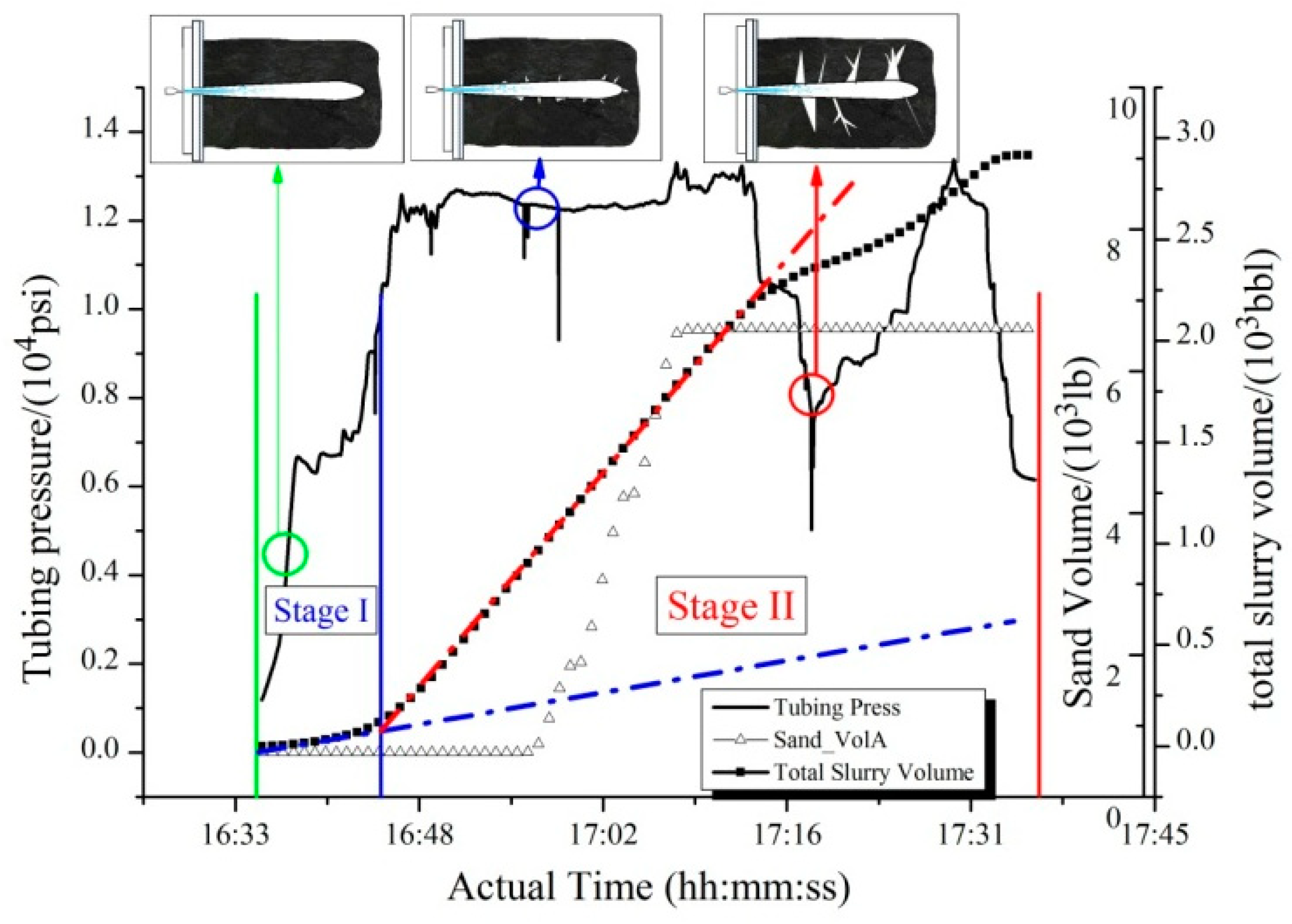
Figure 1. Schematic representation of the hydro-jet fracturing process.
Energies 13 02627 g001
Figure 2. Schematic representation of two different simulation models.
Energies 13 02627 g002
Figure 3. Numerical symmetric model of a SC-CO2 jet in limited perforation.
Energies 13 02627 g003
Figure 4. The effect of pressure and temperature on the variation of the density of CO2; (a) The influence of pressure; (b) The influence of temperature.
Energies 13 02627 g004
Figure 5. The effect of pressure and temperature on the variation of viscosity of CO2. (a) The influence of pressure; (b) The influence of temperature.
Energies 13 02627 g005
Figure 6. The effect of pressure and temperature on the variation of the compressibility coefficient of CO2. (a) The influence of pressure; (b) The influence of temperature.
Energies 13 02627 g006
Figure 7. Axial velocity and static pressure along the axis direction.
Energies 13 02627 g007
Figure 8. The variation of the dynamical parameters of SC-CO2 jet along the axial direction. (a) Static pressure and dynamic pressure; (b) Density and temperature.
Energies 13 02627 g008aEnergies 13 02627 g008b
Figure 9. Schematic representation of the vertical section of the simulation.
Energies 13 02627 g009
Figure 10. Schematic representation of the vertical section of the simulated. (a) L0 = 2; (b) L0 = 1.
Energies 13 02627 g010
Figure 11. Distribution of cross-section dimensionless velocity vs. the Goertler solution. (a) η ≦ 1; (b) η > 1.
Energies 13 02627 g011
Figure 12. The effect of nozzle outlet length on the axial velocity of SC-CO2 jet.
Energies 13 02627 g012
Figure 13. The effect of nozzle outlet length on total pressure and axial static pressure. (a) Total pressure on the perforation; (b) Axial static of jetting.
Energies 13 02627 g013
Figure 14. The effect of nozzle outlet radius on the distribution of total pressure axial velocity. (a) Axial velocity of jetting; (b) Total pressure on the perforation.
Energies 13 02627 g014
Figure 15. The effect of aperture ratio on the distribution of axial velocity and static pressure. (a) Axial velocity of jetting; (b) Total pressure on the perforation.
Energies 13 02627 g015
Figure 16. The similar Reynolds number between field practice and experiments.
Energies 13 02627 g016
Figure 17. The schematic program of the visualized vessel and assisted testing facilities.
Energies 13 02627 g017
Figure 18. The High-speed photograph of SC-CO2 jet. (a) The development of a SC-CO2 jet; (b) Instantaneous flow field.
Energies 13 02627 g018
Table 1. The verification between the numerical results and He’s experiments [17].
Verified Group123
ItemExp.Sim.Exp.Sim.Exp.Sim.
Pressure difference (MPa)3.983.9399.118.9914.1513.95
Jet inlet pressure (MPa)14.9613.93920.0318.9925.0823.87
Ambient pressure (MPa)10.9810.0010.9210.0010.9310.00
Measured tunnel pressure (MPa)12.1311.813.1712.2714.2213.64
Pressure increment (MPa)1.151.802.252.273.293.64
Table 2. Numerical simulation scheme.
ItemValue
Nozzle outlet length (mm)1/2/3/4
Nozzle outlet radius (mm)0.75/1/1.5
Nozzle-to-casing inlet radius ratio 2 3 /1/ 4 3