All articles published by MDPI are made immediately available worldwide under an open access license. No special
permission is required to reuse all or part of the article published by MDPI, including figures and tables. For
articles published under an open access Creative Common CC BY license, any part of the article may be reused without
permission provided that the original article is clearly cited. For more information, please refer to
https://www.mdpi.com/openaccess.
Feature papers represent the most advanced research with significant potential for high impact in the field. A Feature
Paper should be a substantial original Article that involves several techniques or approaches, provides an outlook for
future research directions and describes possible research applications.
Feature papers are submitted upon individual invitation or recommendation by the scientific editors and must receive
positive feedback from the reviewers.
Editor’s Choice articles are based on recommendations by the scientific editors of MDPI journals from around the world.
Editors select a small number of articles recently published in the journal that they believe will be particularly
interesting to readers, or important in the respective research area. The aim is to provide a snapshot of some of the
most exciting work published in the various research areas of the journal.
An active coil system is proposed to shield the magnetic field produced by a dynamic wireless power transfer (WPT) system used to power electric vehicles (EVs) in motion. The considered dynamic WPT is based on an electrified road with many short-track pads. A sophisticated mathematical procedure is developed to optimize the design of the active coils configuration and their excitation. By the proposed approach, the resulting magnetic field is compliant with the reference levels (RLs) of the ICNIRP (International Commission on Non-Ionizing Radiation Protection) 2010 Guidelines inside the cabin of EVs and on the side of the electrified road.
The future of road transport will be based on a large use of electric vehicles (EVs). Currently, the EVs are equipped with an internal battery that must be periodically charged, mainly using a plug-in connection. At the moment, one of the most critical issues in EVs is given by the battery, which has high cost, great weight, and long charging time. All these weaknesses lead to a reduced autonomy of the EVs. To overcome these difficulties and to increase safety, the idea is to recharge the battery using a wireless connection instead of a plug-in connection. This is made possible by the technology known as wireless power transfer (WPT), based on inductive coupling between a coil mounted on the road surface and a coil mounted on board the EV [1,2,3,4]. The current experimentation is mainly focused on static WPT, i.e., assuming the EV stopped in a parking spot equipped with a charging station [5,6]. There are also some recent studies on dynamic WPT, i.e., assuming the EV in motion [7,8]. It implies that the road must be electrified, i.e., studded by many separate coils (charging pads), or using a long-track coil. In both cases, using dynamic WPT, the EV battery can be automatically recharged during motion, leading to a significant increase of the EV range that can be practically infinite, as in other electrified transports like trains. Furthermore, the size of the onboard battery can be greatly reduced with a consequent reduction in cost and weight for the vehicle, leading to an important improvement of performance and reduction in consumption. A vehicle with infinite range is perfect for the project of an autonomous driving system.
There are several issues for the practical realization of an electrified road. One of these critical aspects is the electromagnetic pollution produced by the currents flowing in the coils of the WPT system that can generate a time-variable magnetic field in the surrounding environment, i.e., in the cars and in the areas nearby the electrified road where people can stay [9,10,11,12]. The victims of the incident magnetic fields are not only car passengers and pedestrians, but also electrical and electronic devices, which play a big role in the safety of road transportation.
The control and mitigation of the magnetic field is therefore a topic of paramount importance for the development of the next generation EVs. This is also a challenging problem for two main reasons:
i)
Mitigation of low-frequency field is yet an open problem that still remains to be solved.
ii)
Reduction of the magnetic field can negatively affect the inductive coupling between the WPT coils, decreasing the electrical performance.
For problem i) it is well known that at the frequencies in the range 20–100 kHz, which are traditionally used for static and dynamic WPT systems, the penetration depth δ in metallic materials is relatively high (δ = 0.46 mm in copper; δ = 0.58 mm in aluminum; δ = 1.12 mm in iron at 20 kHz; δ = 0.22 mm in copper; δ = 0.28 mm in aluminum; and δ = 0.54 mm iron at 85 kHz). It means that a relatively large amount of the incident field can pass through the conductive shield if the thickness of the shield (or bodyshell) is around 1–3 mm. Furthermore, conductive shields are sites of eddy currents that produce losses decreasing the power transfer efficiency [6,13]. For these reasons the conductive materials are not widely used on board EVs to mitigate the magnetic field. Much better is the shielding produced by magnetic materials as ferrite, but their cost and weight are too high to be extensively adopted in EVs or in electrified roads.
A different option, instead of using shielding materials, is given by the utilization of active or passive coils that generate a magnetic field opposite to the incident one. Passive coils are simply based on Faraday’s law, since a time-varying incident magnetic field gives rise to an electromagnetic force in a coil generating a current when the coil is terminated on an impedance [14]. Using a capacitor as load, the magnetic field generated by the induced current in the coil is opposite to the incident one. The cost of passive coils is very low, and the reaction field spontaneously follows possible variations in frequency and amplitude of the incident field. However, the field mitigation could not be as good as requested in many cases. To overcome this limit, the use of active coils is strongly recommended. They are similar to passive coils, but independently excited in such a way that the current flowing into them is able to produce an opposite field that can almost cancel the incident field. Obviously, the shielding performance of active coils can be very good, but they have to be adequately powered, increasing the complexity of this application [15,16,17,18,19].
Active shielding coils are here proposed to mitigate the magnetic field in dynamic WPT systems for road transport. Contrary to static WPT systems, the dynamic ones are far from a real application and are not yet standardized, but some research projects have been carried out. Mainly there are two kinds of primary coils: long-track pads that are quite similar to excitation rails, or multiple short-track pads that are quite similar to a series of relatively small primary coils studded on the road. The first architecture is better for vehicles, since they have a quite uniform excitation during their motion, but it is not very efficient from an energetic point of view, and the electromagnetic pollution is quite relevant around the long track. The second architecture is more complex, and the vehicles have different excitation during motion, but it is more efficient and the pollution is limited, since the short-track pads are excited one at a time; only when an EV is just above a pad. The second solution is therefore preferred in many projects and adopted in this study. Precisely, we consider the dynamic WPT coil configuration used in Fabric [20], an EU project with many industries and boards. The study presented here deals with the active shielding design of a dynamic WPT system, based on short-track pads powered at 85 kHz. The goal of the shielding is to be compliant with the electromagnetic field (EMF) safety standards and regulations for human exposure inside and beside EVs where pedestrians can stay. Since the area where the field must be mitigated is very large, the mitigation technique must be simple, low cost, and easy to install. In the following, the design of active coils is presented and discussed.
2. Mathematical Method
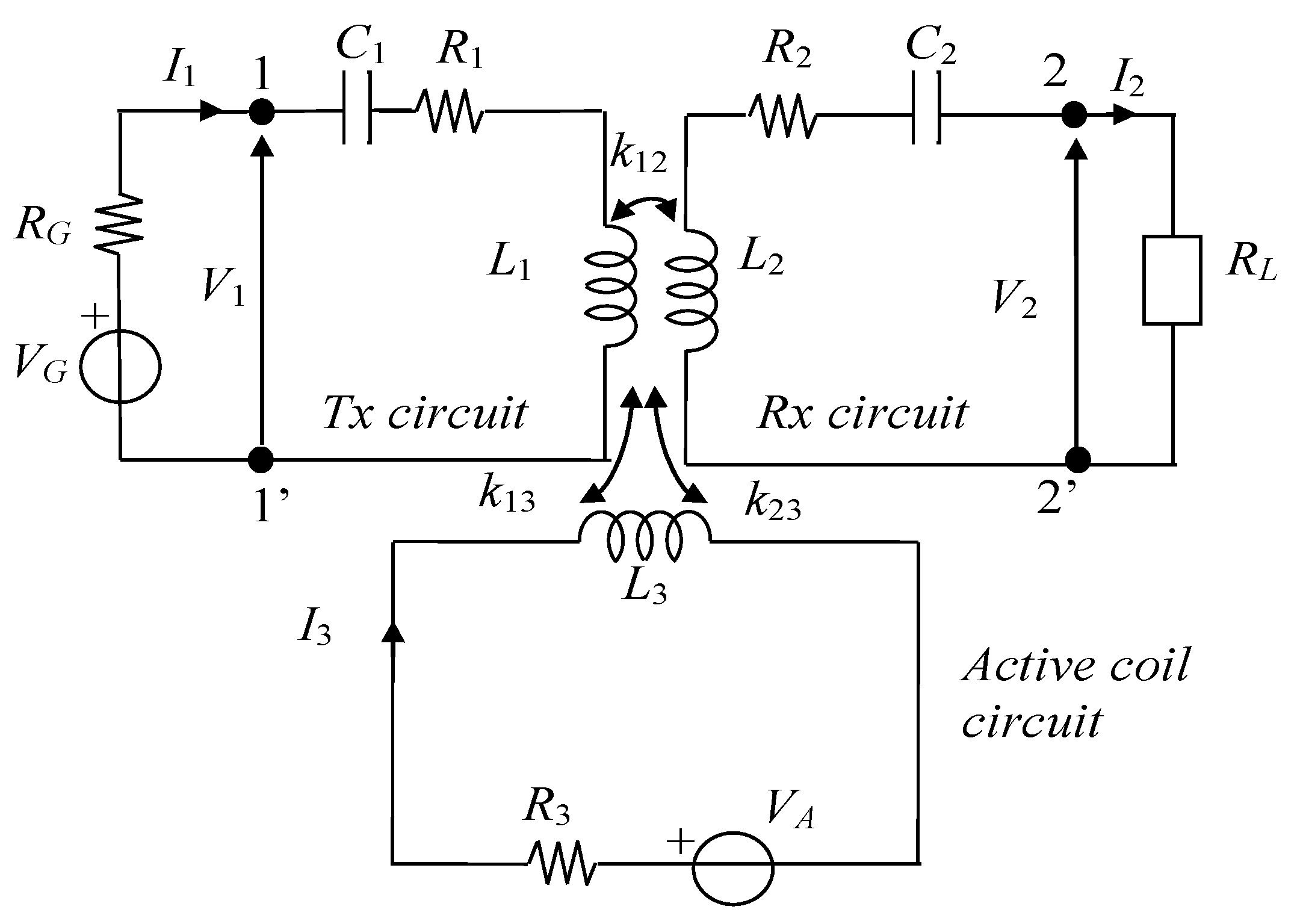
A near field WPT system based on magnetic resonant coupling is considered for the dynamic wireless charging of EVs. The magnetic field generated by the WPT inductive coil currents must be confined, or mitigated, in critical areas. The objective of this research is the mitigation of the magnetic field beside the electrified road line in the sidewalk area typically occupied by pedestrians, runners, road workers, etc. The safeguard of this area is committed to ensuring a magnetic field below the limits, i.e., reference levels (RLs) fixed by the ICNIRP (International Commission on Non-Ionizing Radiation Protection) 2010 Guidelines [21], and is obtained by the use of active shielding coils. The equivalent circuit of a two-coil WPT system with an active shielding coil is composed by three circuital meshes representing the WPT primary (or transmitting (Tx)) circuit, the WPT secondary (or receiving (Rx)) circuit, and the active coil circuit, respectively, as shown in Figure 1. The primary circuit is powered by a voltage generator, VG, with an internal resistance, RG, the secondary circuit is terminated on a resistive load, RL, representing the charging circuit of the EV battery, and the active shielding coil is powered by a voltage generator, VA. The equivalent circuit represents a simplified model of the system where all electronic components (inverter, rectifier, etc.) are modeled by simplified analogical devices at resonance. In the circuit R1, R2, and R3 are the series resistances of the Tx, Rx, and active coils, respectively, L1, L2, and L3 are the coil self-inductances, k12, k23, and k13 are the coupling factors among coupled inductors, C1 and C2 are the series compensation capacitors obtained by C1 = 1/(ω2L1) and C2= 1/(ω2L2) assuming a series-series (SS) compensation topology, and ω = 2πf is the angular frequency, f being the resonance frequency.
The mesh equations of the equivalent circuit written in matrix form are [15]:
or in a more compact form as:
where [Z] is the impedance matrix. The mesh current vector [I] can be obtained via Equation (2) as:
The matrix [Z] is invertible, as the rows of the matrix are linearly independent. Indeed, all main diagonal elements of [Z] are real or complex with positive real parts, while the mutual terms of the matrix [Z] are all purely imaginary. Assuming linearity, the magnetic flux density at the jth generic point produced by the m coil currents, I1, I2, I3, can be expressed applying superposition as:
where bk,x, bk,y and bk,z are the x, y, z components of the magnetic flux density generated by a unit current flowing in the kth coil, with k = 1,…,m and m = 3 [15]. Equation (4) can be rewritten in matrix form:
Let us now consider a cloud of n points. By writing the equation systems Equation (5) for these n points and considering Equation (3), the following matrix form is obtained:
that can be also written in compact form as:
where [Bxyz] is a 3n × 1 vector, [b] is a 3n × m matrix, [Z] is a m × m matrix, and [V] is a m × 1 vector. At each point (xj,yj,zj) with j = 1,…,n of the cloud, the transfer function vector [bk,x(x,y,z) bk,y(x,y,z) bk,z(x,y,z)]T is calculated, taking into account the field produced by the currents flowing into each of the m coils. Manipulating Equation (7) it yields:
where [S] = [b] [Z]-1 = [[g1] [g2] [g3]] is a 3n × m matrix, being [g1], [g2], [g3] 3n × 1 vectors. From Equation (8) when imposing [Bxyz] = 0 for the field minimization, it is derived:
It should be convenient to use a voltage-controlled voltage source VA = α VG to power the active coil, automatically adapting the shielding field to the incident one which is related to the voltage source VG. Thus, Equation (9) becomes:
To determine the parameter α that controls the voltage-controlled voltage source of the active coil, VG is assumed to be initially constant, and then the norm of is minimized. It should be noted that, if we consider the squared norm of Equation (10), we obtain:
where the left-hand side of Equation (11) is a 3n column vector and B(xj, yj, zj) is a 3-column vector. The summation on the right side of Equation (11) is proportional to the average value of B in the cloud of n points inside the region to be shielded. Minimizing Equation (11) we find the value of α such that the average value of B over the n considered points is minimum. The value of the unknown term α that minimizes Equation (11) can be then obtained applying the pseudoinverse as [15]:
In order to deliver the exact same amount of power in both cases (with and without the active shield) the value of the generator voltage VG used in the case without active shield is rescaled by a factor λ:
where Pout,REQ is the required power from the load, and Pout,CALC is the power calculated using the unscaled value of VG. Obviously, being VA = αVG, the voltage-controlled source VA is also rescaled when rescaling VG.
The power transfer efficiency η of the system is calculated, taking into account the losses due to the presence of the active coil as:
where Pin = real (V1I1) is the input real power at port 1-1′, Pout = real (V2I2) is the output real power at port 2-2′, and Pact = R3|I3|2 is the power used by the active coil, where all electrical quantities are shown in Figure 1.
3. Method Validation
To validate the proposed method, a simple WPT system was considered. The WPT system was composed of two circular planar stacked coils with a single active shielding coil, as shown in Figure 2. The identical WPT coils had an external radius, rc = 4 cm, and number of turns, N = 10. The separation distance between the primary and the secondary coil was set to dc = 4 cm. The coils were realized with Litz Wire to reduce the losses. The series-series compensation topology was adopted and the capacitors were chosen to reach the resonant condition at the operational frequency of f = 85 kHz. The load of the system was a simple resistor RL = 10 Ω. The active shield was composed in this validation test by a semi-annular shaped coil with dimensions: internal radius rsi = 15 cm, and external radius rse = 30 cm. The magnetic field was minimized in a cloud of n = 3 × 3 × 3 = 27 equidistant points inside a 5 × 5 × 5 cm3 cubic region whose center p has distance dp = 40 cm from the vertical axis of the WPT coils.
The self and mutual inductances and resistances were measured using an LCR meter (Keysight E4980A). They were also calculated as described in [15]. The measured and calculated results are reported in Table 1.
The coil current and voltage were also measured. The WPT system is powered by a full bridge inverter, that amplifies the signal given from a signal generator. The input voltage was adjusted to obtain the fixed output power on the load. The magnetic field produced by the WPT coils in the point p was measured by the field probe described in [22]. The measured and calculated results, in terms of electrical performances and magnetic field, are reported in Table 2 without active shielding [15].
Then, the procedure described in Section 2 for the shielding coil was applied to minimize the field in the region to be shielded, i.e., a cubic region around point p, with dimensions comparable to the size of the magnetic field sensor. At the end of the numerical procedure, the values of module and phase of the shielding current were obtained as |I3| = 0.89 A and φ3 = 197°, respectively, when assuming zero phase for the primary current I1. Finally, the active coil was powered, injecting I3 into the coil by a separate inverter, driven by auxiliary output of the signal generator, to permit a total control of the phase injected to the coil. The system efficiency η, the magnetic flux density B at point p, and the shielding effectiveness (SE = 20 log10 (Bw/o_shield / Bwith_shield)) were obtained with active shielding, as reported in Table 3. The measured and calculated results highlight that a significant field reduction (SE = 18.1 dB) at this frequency leads to a very little decrease of WPT efficiency (only one percentage point).
4. Applications
The proposed shielding method is applied to the dynamic WPT system described in [20]. The considered system adopts multiple sequential short-track primary pads that are mounted on the road. For safety and efficiency reasons, the primary coils are activated one at a time, only when the presence of the secondary coil mounted on the car underbody is detected. Thus, this system can be analyzed similarly to a typical static WPT system, considering different positions of the secondary coil along the electrified road. A sketch of the configuration is shown in Figure 3, where just one short-track primary pad is depicted. The vertical distance between primary and secondary coil is set equal to d12= 20 cm. The battery load and all the electronics attached to the secondary coil are modeled by a simple equivalent resistor RL = 4 Ω. The planar transmitting coils in the xy plane have a narrow rectangular shape, with the long side parallel to the road direction (x axis) to ensure the transmission of the power for a longer period. The external dimensions of the primary coil are: ltx = 150 cm and wty = 50 cm. The secondary coil also has a rectangular shape, but in this case the long side is in the y direction, to improve the tolerance to possible lateral misalignment. The dimensions of the secondary coil are: lrx = 50 cm and wrx = 60 cm. On the receiving coil, two ferrite blocks are adopted with rectangular shape of dimensions wfe × lfe = 15 cm × 25 cm and thickness tfe = 0.5 cm. These ferrite blocks are in the pick-up coil design of the Fabric project [20], and they are used to enhance the electrical performances by improving the magnetic field behavior due to the reduction of the reluctance. The primary and secondary coils both have N = 10 turns and are realized with a Litz Wire made of 1260 strands of AWG (American wire gauge) 38 insulated wires, to reduce the power losses. In our simulations we have considered an SUV vehicle. The dimensions of the metallic bodyshell shown in Figure 4 are: length 423 cm, height 144 cm, and width 180 cm. The car body is modeled with aluminum alloy panels having thickness t = 2 mm and electrical conductivity σ = 30 MS/m.
The active coil configuration was designed following the guideline described in [15] for static WPT systems. The main idea was to design an active coil so that the magnetic flux generated by the active coil cancels (or at least minimizes) the magnetic field generated by the WPT coils. Also, the coupling factor is minimized between the WPT coils and the shielding coil, to avoid a negative impact on the WPT efficiency. To this aim, a simple rectangular coil (in green in Figure 4), mounted on the ground near the primary coil, is adopted and made by the same Litz wire used for the other coils. The dimensions of the active coil are: lsx = 160 cm and wsx = 20 cm. The center of the Cartesian axes (0,0,0) corresponds to the center of the primary coil, while the secondary coil, attached to the vehicle, moves along the x-axis. The shielding coil has been centered in (0, 60, 0) cm in order to reduce the coupling with the WPT coils and in such a way that the secondary coil never overlaps the active coil in case of the coil’s lateral misalignment, and also to avoid a pedestrian covering the shielding coil. The lumped parameters are calculated by a procedure described in [23]. To accurately model the resistance of Litz wires, datasheets have been used. The calculated self-inductances and resistances are shown in Table 4, while the mutual coupling coefficients depend on the vehicle position as shown in Table 5. To take into account the movement of the vehicle, three different positions of the secondary coil center are considered with the following coordinates in cm: x1(0, 0, d12), x2(25, 0, d12), x3(50, 0, d12). The lumped inductances and coupling factors were extracted by a numerical procedure based on the solution of the magneto quasi static (MQS) field equations, with a code based on the finite element method (FEM). The field penetration through the vehicle bodyshell was taken into account by transition impedance boundary conditions [24]. The computational domain was discretized by 106033 tetrahedral finite elements with second order interpolation functions.
The considered region to be shielded is in centimeters {−80 ≤ x ≤ 80, −125 ≤ y ≤ −90, −5 ≤ z ≤45} that is discretized in n = 6750 points. In this region, shown in Figure 4 by a green box, the minimization is done on the average value of the norm of B. The constant value of the delivered power is ensured via (13) varying the input voltage. After applying the method described in Section 2, we have calculated the magnetic field without, and with, the active shield. The calculations are performed imposing a constant value of delivered power to the load Pout = 10 kW. The rms source voltages and currents flowing through the coils for different positions of the secondary coil center along x axis are reported in Table 6, Table 7 and Table 8.
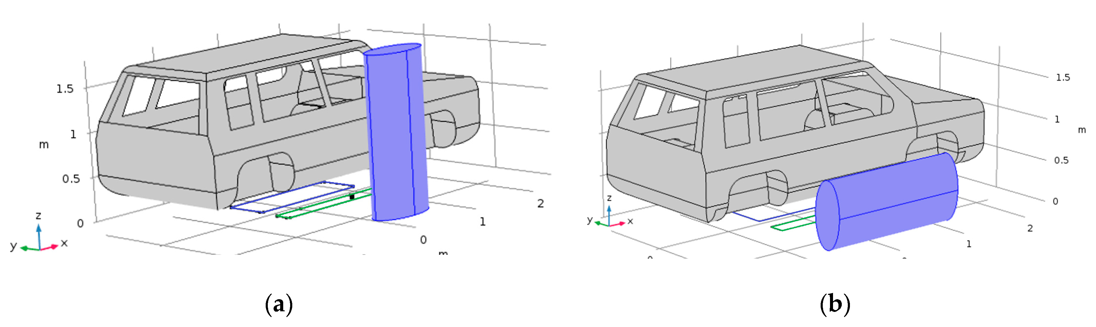
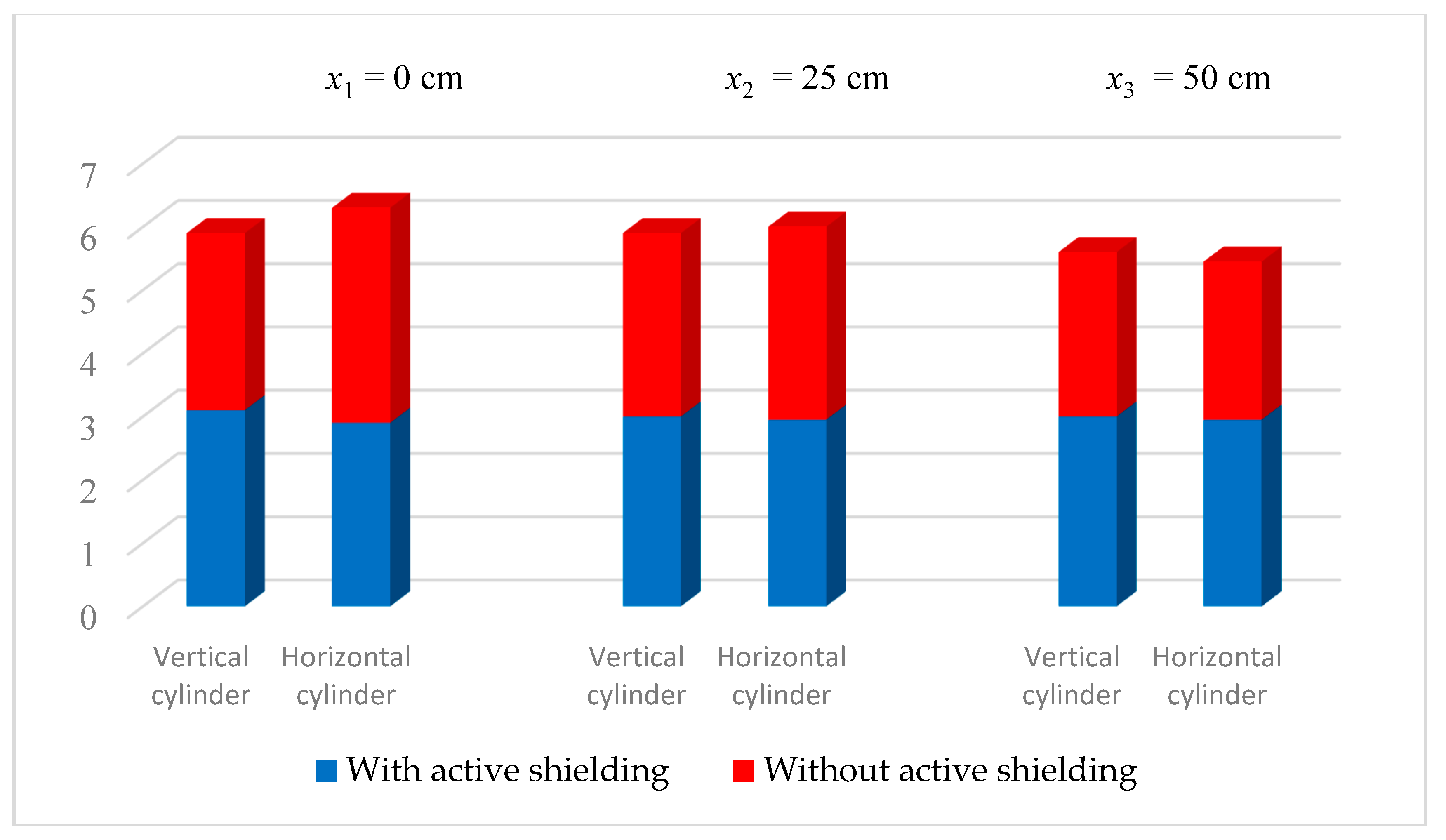
As can be seen from the obtained results, the influence of the active shield has a very small influence on the efficiency of the WPT system, with a power loss of about 1%. Then, the attention was focused on the performance in terms of magnetic field reduction. A cylinder with height 180 cm and elliptical base with semi-major axis of 40 cm and semi-minor axis of 20 cm is considered. The elliptical cylinder represents a respect volume. At any point inside this volume the magnetic field must be below the limit fixed by international regulations, which in Europe are mainly the RLs of the ICNIRP 2010 Guidelines. The RL in terms of magnetic flux induction at 85 kHz is equal to 27 µT for the ICNIRP 2010 and equal to 6.25 µT for the ICNIRP 1998 [25], still valid in some countries, due to the not repealed or adjourned European Council Recommendation [26]. Two positions of the respect volume near the EV are considered. The vertical cylinder of Figure 5a represents a respect volume for a pedestrian standing near the vehicle, while the horizontal cylinder of Figure 5b represents a respect volume for a pedestrian lying down on the side of the road near the vehicle. The maximum values of magnetic flux induction B inside the vertical and horizontal cylindrical regions (see Figure 5) are shown in Figure 6. A field reduction of more than 50% is observed in both cylindrical regions. These results are very satisfactory.
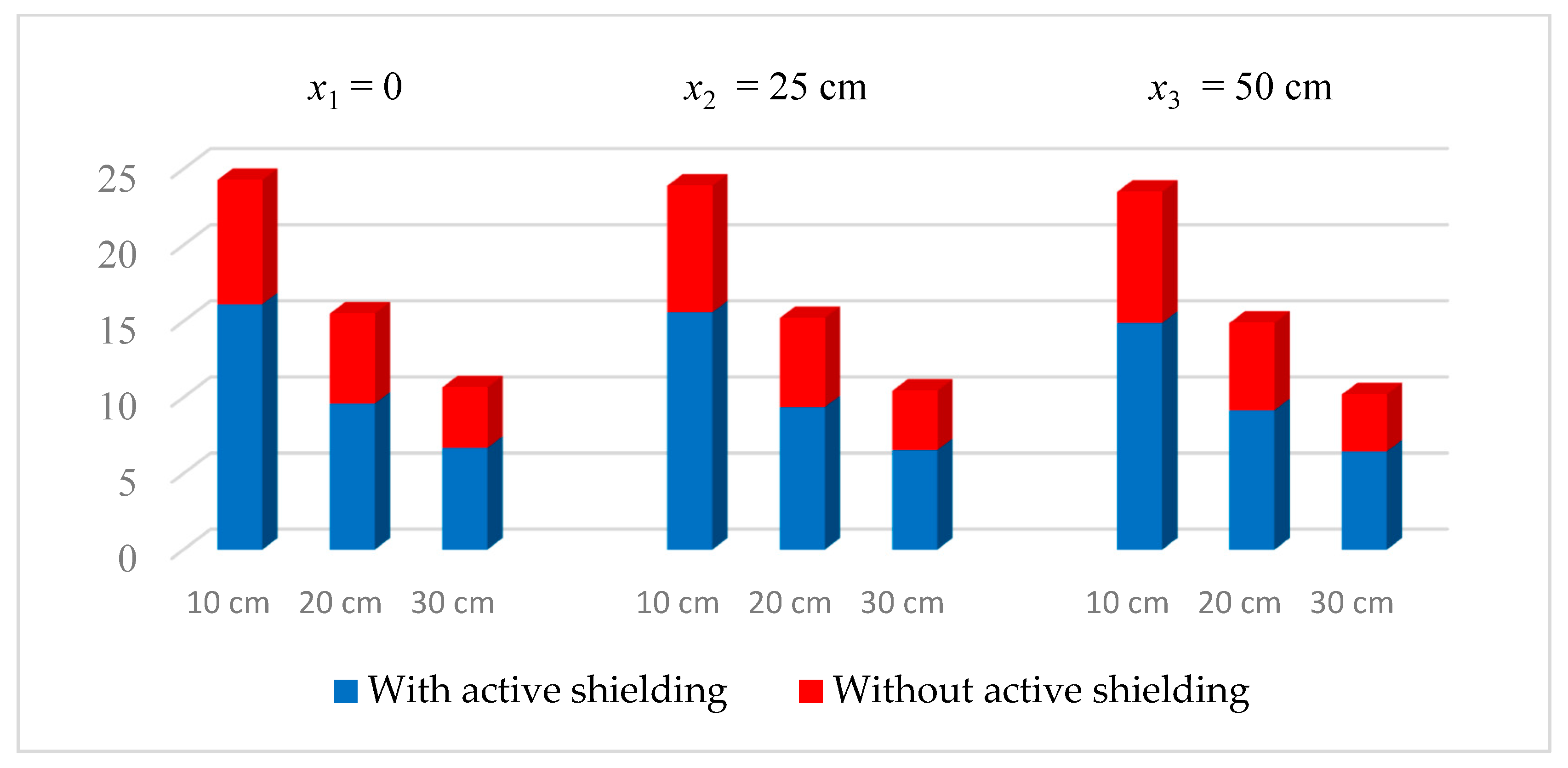
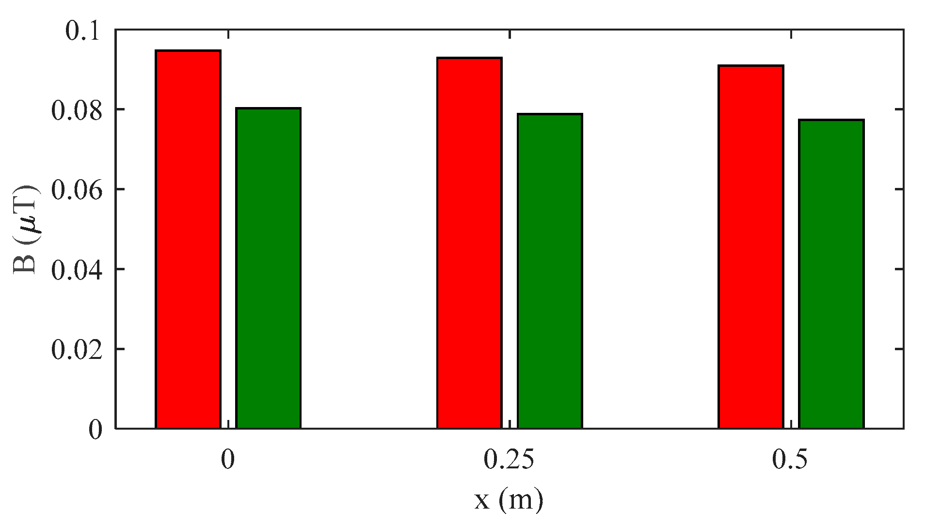
The maximum value of the magnetic flux induction beside the vehicle has been calculated on an xz plane for three different positions of the secondary coil center along the x-axis (x1 = 0, x2 = 25 cm, x3 = 50 cm) at lateral distances of 10 cm (a), 20 cm (b), and 30 cm (c) from the vehicle body, as shown in Figure 7. These lateral distances correspond to y = −100 cm (a), y = −120 cm (b), and y = −120 cm (c), respectively, for the considered vehicle dimensions. A field reduction between 33% and 39% was obtained. Without active shielding, the field is very close to the ICNIRP 2010 RL of 27μT, while the use of the active coil permits a considerable safety margin at any distance. Around a lateral distance of 30 cm, the magnetic flux induction is also compliant with the ICNIRP 1998 RL of 6.25 µT.
The B-maps on a plane xz beside the vehicle at a lateral distance of 10 cm for three different positions of the secondary coil center along the x-axis (x1 = 0, x2 = 25 cm, x3 = 50 cm in Figure 3) are shown in Figure 8, Figure 9 and Figure 10 without, and with, active shielding.
Inside the vehicle cabin in a xy plane at a distance of 20 cm (z = 50 cm) from the vehicle bottom, we have found that the maximum of the magnetic field norm is marginally lower in the case of active shielding. However, the field level is always below 100 nT, as shown in Figure 11. This means that the active shielding designed to mitigate the field in a region beside the vehicle does not increase the magnetic field inside the cabin.
Finally, it should be noted that we assume the dynamic behavior of WPT systems as a sequence of static states. To this aim, we considered only three positions for the receiving coil; however, the optimal shielding current can be easily derived for all the positions. Moreover, an automatic shielding current regulator can be realized using the current on both the transmitting and receiving coils as feedback for the regulation, to obtain the optimal shielding efficiency at any instant.
5. Conclusions
A method to reduce the magnetic field produced by a dynamic power transfer system using active shielding coils is presented. The proposed method allows halving of the magnetic field in proximity of the vehicle. First, the theory of active shielding is explained, and the method to calculate the optimum current to be applied to the active coils is provided, to minimize the field in the most critical areas. Then, an experimental validation of the calculation method is carried out by measurements on a simplified configuration. Finally, the procedure is applied to a dynamic WPT system, based on an electrified road with many short-track pads. Very good results were obtained in terms of field reduction without a significant degradation of the electrical performances. The main obtained results are: the active shielding coils halve the magnetic flux induction beside the electrified road where humans can stay; the field levels are compliant with ICNIRP reference levels; the magnetic field inside the cabin is not increased by the active coils; the losses in the active coils are very limited; and the decrease in the power transfer efficiency is around one percentage point, due to presence of the losses in the active coil. Finally, although not addressed in this paper, the implementation of the active shielding coil technology should be very simple and low-cost.
Author Contributions
Conceptualization, S.C. and M.F.; Formal analysis, M.F. and F.M.; Methodology, S.C. and T.C.; Software, S.C. and T.C.; Measurements, T.C.; Supervision, F.M. and M.F.; Writing–original draft, S.C. T.C., F.M. and M.F.; Writing–review & editing, S.C., T.C., F.M. and M.F. All authors have read and agreed to the published version of the manuscript.
Funding
This research was funded by the University of L’Aquila, L’Aquila, Italy.
Conflicts of Interest
The funding sponsors had no role in: the design of the study; in the collection, analyses, or interpretation of data; in the writing of the manuscript; and in the decision to publish the results.
References
Covic, G.A.; Boys, J.T. Inductive power transfer. Proc. IEEE2013, 101, 1276–1289. [Google Scholar] [CrossRef]
Shinohara, N. Power without wires. IEEE Microw. Mag.2011, 11, 64–73. [Google Scholar] [CrossRef]
Wang, C.-S.; Covic, G.A.; Stielau, O.H. Power Transfer Capability and Bifurcation Phenomena of Loosely Coupled Inductive Power Transfer Systems. Trans. Ind. Electron.2004, 51, 148–157. [Google Scholar] [CrossRef]
Ahmad, A.; Alam, M.S.; Chabaan, R.A. Comprehensive Review of Wireless Charging Technologies for Electric Vehicles. Trans. Transport. Electrific.2018, 4, 38–63. [Google Scholar] [CrossRef]
Zhai, L.; Zhong, G.; Cao, Y.; Hu, G.; Li, X. Research on Magnetic Field Distribution and Characteristics of a 3.7 kW Wireless Charging System for Electric Vehicles under Offset. Energies2019, 12, 392. [Google Scholar] [CrossRef]
Feliziani, M.; Cruciani, S. Mitigation of the magnetic field generated by a wireless power transfer (WPT) system without reducing the WPT efficiency. In Proceedings of the International Symposium on Electromagnetic Compatibility, Brugge, Belgium, 2–6 September 2013; pp. 610–615. [Google Scholar]
Laporte, S.; Coquery, G.; Deniau, V.; De Bernardinis, A.; Hautière, N. Dynamic wireless power transfer charging infrastructure for future evs: From experimental track to real circulated roads demonstrations. World Electr. Veh. J.2019, 10, 84. [Google Scholar] [CrossRef]
Buja, G.; Rim, C.T.; Mi, C.C. Dynamic Charging of Electric Vehicles by Wireless Power Transfer. IEEE Trans. Ind. Electron.2016, 63, 6530–6532. [Google Scholar] [CrossRef]
De Santis, V.; Campi, T.; Cruciani, S.; Laakso, I.; Feliziani, M. Assessment of the Induced Electric Fields in a Carbon-Fiber Electrical Vehicle Equipped with a Wireless Power Transfer System. Energies2018, 11, 684. [Google Scholar] [CrossRef]
Ding, P.; Bernard, L.; Pichon, L. Evaluation of Electromagnetic Field in Human Body Exposed to Wireless Inductive Charging System. IEEE Trans. Magn.2014, 50, 1037–1040. [Google Scholar] [CrossRef]
Laakso, I.; Hirata, A. Evaluation of the induced electric field and compliance procedure for a wireless power transfer system in an electrical vehicle. Phys. Med. Biol.2013, 58, 7583. [Google Scholar] [CrossRef] [PubMed]
Kim, H.; Song, C.; Kim, D.H.; Jung, D.H.; Kim, I.M.; Kim, Y.I.; Kim, J.; Ahn, S.; Kim, J. Coil design and measurements of automotive magnetic resonant wireless charging system for high-efficiency and low magnetic field leakage. IEEE Trans. Microw. Theory Tech.2016, 64, 383–400. [Google Scholar] [CrossRef]
Campi, T.; Cruciani, S.; Feliziani, M. Magnetic Shielding of Wireless Power Transfer Systems. In Proceedings of the International Symposium on Electromagnetic Compatibility, Tokyo, Japan, 13–16 May 2014. [Google Scholar]
Mohammad, M.; Wodajo, E.T.; Choi, S.; Elbuluk, M.E. Modeling and Design of Passive Shield to Limit EMF Emission and to Minimize Shield Loss in Unipolar Wireless Charging System for EV. IEEE Trans. Power Electron.2019, 34, 12235–12245. [Google Scholar] [CrossRef]
Cruciani, S.; Campi, T.; Maradei, F.; Feliziani, M. Active shielding design for wireless power transfer systems. IEEE Trans. Electromag. Compat.2019, 61, 1953–1960. [Google Scholar] [CrossRef]
Park, J.; Kim, D.; Hwang, K.; Park, H.H.; Kwak, S.I.; Kwon, J.H.; Ahn, S. A Resonant Reactive Shielding for Planar Wireless Power Transfer System in Smartphone Application. IEEE Trans. Electromagn. Compat.2017, 59, 695–703. [Google Scholar] [CrossRef]
Campi, T.; Cruciani, S.; Maradei, F.; Feliziani, M. Active coil system for magnetic field reduction in an automotive wireless power transfer System. In Proceedings of the 2019 International Symposium on Electromagnetic Compatibility, Signal & Power Integrity (EMC+ SIPI), New Orleans, LA, USA, 22–29 July 2019. [Google Scholar] [CrossRef]
Moon, H.; Kim, S.; Park, H.H.; Ahn, S. Design of a resonant reactive shield with double coils and a phase shifter for wireless charging of electric vehicles. IEEE Trans. Magn.2015, 51, 1–4. [Google Scholar] [CrossRef]
Kim, S.; Park, H.; Kim, J. Design and Analysis of a Resonant Reactive Shield for a Wireless Power Electric Vehicle. IEEE Trans. Microw. Theory Tech.2014, 62, 1057–1066. [Google Scholar] [CrossRef]
Guidelines for limiting exposure to time-varying electric and magnetic fields for low frequencies (1 Hz–100 kHz). International Commission on Non-Ionizing Radiation Protection. Health Phys.2010, 99, 818–836. [Google Scholar]
Reticcioli, E.; Campi, T.; De Santis, V. An automated scanning system for the acquisition of non-uniform time-varying magnetic fields. IEEE Trans. Instrum. Meas.2019. [Google Scholar] [CrossRef]
Cruciani, S.; Campi, T.; Feliziani, M.; Maradei, F. Optimum coil configuration of wireless power transfer system in presence of shields. In Proceedings of the 2015 IEEE International Symposium on Electromagnetic Compatibility (EMC), Dresden, Germany, 16–22 August 2015; pp. 720–725. [Google Scholar] [CrossRef]
Guidelines for limiting exposure to time-varying electric, magnetic, and electromagnetic fields (up to 300 GHz). International Commission on Non-Ionizing Radiation Protection. Health Phys.1998, 74, 494–522. [Google Scholar]
Council of the European Union. 1999/519/EC: Council Recommendation of 12 July 1999 on the Limitation of Exposure of the General Public to Electromagnetic Fields (0 Hz to 300 GHz); Council of the European Union: Brussels, Belgium, 1999; Available online: https://op.europa.eu/en/publication-detail/-/publication/9509b04f-1df0-4221-bfa2-c7af77975556 (accessed on 1 April 2020).
Figure 1.
Equivalent circuit of a 2-coil wireless power transfer (WPT) system and an active shielding coil.
Figure 1.
Equivalent circuit of a 2-coil wireless power transfer (WPT) system and an active shielding coil.
Figure 2.
Sketch of the configuration for the validation test (a) and measurement setup (b).
Figure 2.
Sketch of the configuration for the validation test (a) and measurement setup (b).
Figure 3.
Electromagnetic configuration of the WPT coil system with a lateral active coil.
Figure 3.
Electromagnetic configuration of the WPT coil system with a lateral active coil.
Figure 4.
Vehicle bodyshell with WPT and active coils (Tx coil in blue, Rx coil in red, active coil in green) and region to be shielded in green.
Figure 4.
Vehicle bodyshell with WPT and active coils (Tx coil in blue, Rx coil in red, active coil in green) and region to be shielded in green.
Figure 5.
Position of the respect volume: vertical (a) and horizontal (b) positions.
Figure 5.
Position of the respect volume: vertical (a) and horizontal (b) positions.
Figure 6.
Maximum of the magnetic flux induction in µT in vertical and horizontal cylinders.
Figure 6.
Maximum of the magnetic flux induction in µT in vertical and horizontal cylinders.
Figure 7.
Maximum of the magnetic flux induction in µT beside the vehicle at a lateral distance of 10 cm, 20 cm, and 30 cm from the car chassis, and for different car positions along x axis.
Figure 7.
Maximum of the magnetic flux induction in µT beside the vehicle at a lateral distance of 10 cm, 20 cm, and 30 cm from the car chassis, and for different car positions along x axis.
Figure 8.
Maps of the norm of B (µT) in an xz plane at a lateral distance of 10 cm from the EV bodyshell for position x1 = 0 without active shielding (a), and with active shielding (b).
Figure 8.
Maps of the norm of B (µT) in an xz plane at a lateral distance of 10 cm from the EV bodyshell for position x1 = 0 without active shielding (a), and with active shielding (b).
Figure 9.
Maps of the norm of B (µT) in an xz plane at a lateral distance of 10 cm from the EV bodyshell for position x2 = 25 cm without active shielding (a), and with active shielding (b).
Figure 9.
Maps of the norm of B (µT) in an xz plane at a lateral distance of 10 cm from the EV bodyshell for position x2 = 25 cm without active shielding (a), and with active shielding (b).
Figure 10.
Maps of the norm of B (µT) in an xz plane at a lateral distance of 10 cm from the EV bodyshell for position x3 = 50 cm without active shielding (a), and with active shielding (b).
Figure 10.
Maps of the norm of B (µT) in an xz plane at a lateral distance of 10 cm from the EV bodyshell for position x3 = 50 cm without active shielding (a), and with active shielding (b).
Figure 11.
Maximum of the magnetic flux induction inside of the vehicle.
Figure 11.
Maximum of the magnetic flux induction inside of the vehicle.
Table 1.
Calculated and measured circuit parameters with active shielding.
Table 1.
Calculated and measured circuit parameters with active shielding.
L1 (μH)
L2 (μH)
L3 (μH)
R1 (mΩ)
R2 (mΩ)
R3 (mΩ)
k12
k13
k23
Calculated
19.1
19.1
1.73
-
-
-
0.288
0.027
0.023
Measured
19.5
19.7
1.98
105
101
52
0.281
0.026
0.023
Table 2.
Calculated and measured quantities in the validation test without active shielding.
Table 2.
Calculated and measured quantities in the validation test without active shielding.
V1 (V)
I1 (A)
V2 (V)
I2 (A)
η (%)
B (μT)
Calculated
3.38
3.35
10
1
89
0.82
Measured
3.52
3.26
10.2
0.97
87
0.89
Table 3.
Calculated and measured quantities in the validation test with active shielding.
Table 3.
Calculated and measured quantities in the validation test with active shielding.
|I3| (A)
φ3 (°)
η (%)
SE (dB)
B (μT)
Calculated
0.89
197
88
20.2
0.08
Measured
0.95
192
86
18.1
0.11
Table 4.
Lumped circuit parameters.
Table 4.
Lumped circuit parameters.
L1 (μH)
L2 (μH)
L3 (μH)
R1 (mΩ)
R2 (mΩ)
R3 (mΩ)
348
175
2.69
350
175
30
Table 5.
Coupling factors vs. secondary coil position.
Table 5.
Coupling factors vs. secondary coil position.
Secondary Coil Center Position along x Axis
k12
k13
k23
x1 = 0 cm
0.0539
0.0287
0.0105
x2 = 25 cm
0.0555
0.0285
0.0103
x3 = 50 cm
0.0576
0.0285
0.0091
Table 6.
Currents and voltages (rms values) and efficiency for secondary coil position x1 = 0 cm.
Table 6.
Currents and voltages (rms values) and efficiency for secondary coil position x1 = 0 cm.
VG (V)
VA (V)
I1 (A)
I2 (A)
I3 (A)
η (%)
Without active shield
388.43
-
27.55
50
-
93.4
With active shield
407.31
92.07
26.49
50
73.61
92.2
Table 7.
Currents and voltages (rms values) and efficiency for secondary coil position x2 = 25 cm.
Table 7.
Currents and voltages (rms values) and efficiency for secondary coil position x2 = 25 cm.
VG (V)
VA (V)
I1 (A)
I2 (A)
I3 (A)
η (%)
Without active shield
399.63
-
26.75
50
-
93.6
With active shield
416.64
86.97
25.77
50
69.80
92.4
Table 8.
Currents and voltages (rms values) and efficiency for secondary coil position x3 = 50 cm.
Table 8.
Currents and voltages (rms values) and efficiency for secondary coil position x3 = 50 cm.
Cruciani, S.; Campi, T.; Maradei, F.; Feliziani, M.
Active Shielding Applied to an Electrified Road in a Dynamic Wireless Power Transfer (WPT) System. Energies2020, 13, 2522.
https://doi.org/10.3390/en13102522
AMA Style
Cruciani S, Campi T, Maradei F, Feliziani M.
Active Shielding Applied to an Electrified Road in a Dynamic Wireless Power Transfer (WPT) System. Energies. 2020; 13(10):2522.
https://doi.org/10.3390/en13102522
Chicago/Turabian Style
Cruciani, Silvano, Tommaso Campi, Francesca Maradei, and Mauro Feliziani.
2020. "Active Shielding Applied to an Electrified Road in a Dynamic Wireless Power Transfer (WPT) System" Energies 13, no. 10: 2522.
https://doi.org/10.3390/en13102522
APA Style
Cruciani, S., Campi, T., Maradei, F., & Feliziani, M.
(2020). Active Shielding Applied to an Electrified Road in a Dynamic Wireless Power Transfer (WPT) System. Energies, 13(10), 2522.
https://doi.org/10.3390/en13102522
Note that from the first issue of 2016, this journal uses article numbers instead of page numbers. See further details here.
Article Metrics
No
No
Article Access Statistics
For more information on the journal statistics, click here.
Multiple requests from the same IP address are counted as one view.
Cruciani, S.; Campi, T.; Maradei, F.; Feliziani, M.
Active Shielding Applied to an Electrified Road in a Dynamic Wireless Power Transfer (WPT) System. Energies2020, 13, 2522.
https://doi.org/10.3390/en13102522
AMA Style
Cruciani S, Campi T, Maradei F, Feliziani M.
Active Shielding Applied to an Electrified Road in a Dynamic Wireless Power Transfer (WPT) System. Energies. 2020; 13(10):2522.
https://doi.org/10.3390/en13102522
Chicago/Turabian Style
Cruciani, Silvano, Tommaso Campi, Francesca Maradei, and Mauro Feliziani.
2020. "Active Shielding Applied to an Electrified Road in a Dynamic Wireless Power Transfer (WPT) System" Energies 13, no. 10: 2522.
https://doi.org/10.3390/en13102522
APA Style
Cruciani, S., Campi, T., Maradei, F., & Feliziani, M.
(2020). Active Shielding Applied to an Electrified Road in a Dynamic Wireless Power Transfer (WPT) System. Energies, 13(10), 2522.
https://doi.org/10.3390/en13102522
Note that from the first issue of 2016, this journal uses article numbers instead of page numbers. See further details here.


