Article

Thermodynamic, Economic, and Environmental Analyses of a Waste-Fired Trigeneration Plant

by
Hossein Nami
1,
Amjad Anvari-Moghaddam
2,3,* and
Ahmad Arabkoohsar
2
1
Department of Mechanical Engineering, Faculty of Engineering, University of Maragheh, Maragheh 83111-55181, Iran
2
Department of Energy Technology, Aalborg University, 9220 Aalborg, Denmark
3
Faculty of Electrical and Computer Engineering, University of Tabriz, Tabriz 5166616471, Iran
*
Author to whom correspondence should be addressed.
Energies 2020, 13(10), 2476; https://doi.org/10.3390/en13102476
Submission received: 11 April 2020 / Revised: 4 May 2020 / Accepted: 12 May 2020 / Published: 14 May 2020
(This article belongs to the Section C: Energy Economics and Policy)

Abstract

:
The global energy matrix is going to embrace more and more renewable-based combined energy systems. Therefore, multi-generation energy systems, like CHPs (combined heat and power) could be extremely beneficial for such integrated energy systems. Also, the trend is toward 100% sustainable production where both renewable and waste energy sources are of special value. Especially, in Europe, waste incineration has received special attention over the past decades, as not only it is a smart method of waste disposal, but also a measure of cheap and environmentally friendly energy production. This study proposes a municipal waste-driven tri-generation (cold, heat, and power) system and assesses how this solution helps for easier integration of energy sectors and having a more sustainable chain of energy supply. Then, the solution is comprehensively analyzed over thorough thermodynamic, thermoeconomic, and thermoenvironmental investigations. The results of the assessments show that the proposed trigeneration system may effectively operate in any energy systems with simultaneous cold, heat, and power demands. Thermal, exergetic, fuel-to-power, fuel-to-heat, and fuel-to-cold efficiencies are found to be 83.28, 25.69, 23.49, 47.41, and 12.38%, respectively, while the payback period of 6 years is obtained based on the net present method.

1. Introduction

Co-generation and tri-generation systems are proved to be smart tools for increasing energy and cost efficiency of supply via the recovery of an energy flow (mainly heat) which is otherwise wasted [1]. Apart from this fact, the importance of such multi-generation plants is increasing today because of the growing need for integrated energy systems where all the energy demands such as electricity, cold, and heat have synergies with each other [2]. These synergies are to create the opportunity of transferring cheap-excess energy from one sector to another one while increasing efficiency and decreasing the cost of supply at the same time [3]. Having said this, one may feel the importance of not only revising the sole-production energy plants for a possible co-/tri-generation design but also introducing new effective tools for multi-generation [4].
Aghbashlo et al. [5] presented a comprehensive exergoeconomic analysis for the combination of biogas genset and municipal solid waste digestion plant. Obtaining the cost structure of the combined plant was the main purpose of this study. The unit cost of products was determined to be 2.27 and 26.27 USD/GJ for the biofertilizer and bioelectricity, respectively. Also, an economic investigation showed that the most important component is the genset followed by digester with the cost rates of 101.27 and 68.41 USD/h, respectively. Thermodynamic and economic performance of a dual-fuel cogeneration system operating with natural gas (NG) and biomass as an energy supplier for a hotel was investigated by Yang et al. [6]. They claimed that dual-fuel CCHP system can be proposed as an interesting solution from the cost-effective operation point of view. It was shown that the system exergetic efficiency during the winter and summer is 12.23 and 8.06%, respectively. They concluded also that the gasifier could result in a significant value of exergy destruction (almost 60% of entire exergy destruction). In addition, it was revealed that the product cost could be lower in summer than in winter. A 4E analysis of solar boosted CCHP system operating based on the natural gas fired Brayton cycle was proposed by Wang et al. [7]. Solar energy was utilized to increase the air temperature feeding the combustion chamber and exhaust gases exiting gas turbine were used to generate chilled/hot water. It was reported that the energetic and second law efficiencies could reach 66.0/83.6% and 25.7/24.9%, respectively, in the heating/cooling mode. Besides, it was shown that utilizing solar energy could reduce carbon emission of 41%, approximately. Owebor et al. [8] designed an integrated thermal power plant operating with municipal waste to energy. This system was a combination of gasifier, fuel cell, steam and gas turbine power cycles, ORC, and an absorption chiller. The thermodynamic analysis revealed that the energetic and exergetic efficiencies of the integrated system corresponding to the stack temperature of 54 °C were 62.3 and 55.5%. System exergy performance revealed that the major value of destroyed exergy refers to the incinerator unit (37%). Moreover, the cost of supplied power was found to be 1.8 cent/kWh. A solar-assisted biomass-driven CCHP was analyzed by Wu et al. [9] using exergy and exergoeconomic methodologies. In fact, a dish collector was employed to collect the solar heat in contribution to biomass and steam gasification, while the product gas was utilized to run an internal combustion engine, first, and then to drive an absorption chiller. The unit cost of products was reported to be 16.4, 85.2, 58.8, and 96.1 cent/kWh for the electricity, space cooling (delivered via chilled water), space heating (delivered via warm water), and domestic hot water (delivered via pressurized warm water), respectively. A comprehensive techno-economic evaluation of a CHP running with organic division of municipal solid waste was examined by Yang et al. [10]. Results associated with thermodynamic analysis showed that the CHP could operate with an efficiency of almost 60%. Furthermore, economic results revealed that a plant with a capacity of 5 ton per hour requires 27.64 million British pounds as capital investment cost. Yari et al. [11] compared employing gasifier and digester in a fuel cell-based cogeneration system fed by municipal solid waste. Also, a parametric study was done to examine the effects of stack temperature and current density on the system’s performance. According to the reported results, a cogeneration system operating with digester was more favorable than that of operating with a gasifier. Jack and Oko [12] proposed a reheat steam cycle to produce electricity from municipal solid waste for the case of Port Harcourt city. They used exergy and exergoeconomic methodologies to evaluate the proposed system from the thermodynamic and economic perspectives. It was found that $326.4 million is needed to spend as the capital expenditure of a power plant with 117 MW capacity and a payback period of around six years. Nami et al. [13] compared two different small-scale CCHP systems, one operating with steam Rankine cycle and the next with ORC cycle. Both were designed to harvest the waste heat of the cement industry. They demonstrated that energy, exergy, and sustainability principles would select the ORC-based CCHP as the best solution, while the Rankine-based CCHP could be preferable economically.
In this study, a feasibility study of a municipal waste-fired CCHP is presented and the proposed system is examined in detail using technical, economic, and environmental principles. The energetic and exergetic efficiencies are considered as the decisive tool of the thermodynamic analysis, while the exergoeconomic technique is adopted as the economic evaluator implement. Besides, the sustainability index is taken into consideration to show the relationship between the exergetic performance of the system and its environmental impact. In fact, the presented cogeneration system is a combination of waste incineration unit, a steam Rankine cycle, a large-scale LiBr/H2O (lithium bromide-water) absorption chiller, and some auxiliary heat exchangers. The main aim is to design a local energy system feeding the required energy for the neighborhood in terms of power, district heating, and cooling.
In the ref. [14], the authors published on this hybrid plant was simply a thermodynamic analysis of the system explaining the energy and exergy efficiency aspects of the system as compared to a conventional waste-driven CHP plant. While the present study digs into the very detailed thermodynamics (rates of exergy and energy losses and flows, the costs associated with these losses, etc.), economic, and environmental (such as CO2 and NOx emission levels) aspects of the system. This information is informative and essential to know for novel energy systems when are proposed for real-life applications. This results in knowing the most serious drawbacks and loss points/processes of the system and their effects on the economic effectiveness and emission levels of the system and then, proposing suggestions for overcoming these losses/irreversibilities/drawbacks.
The authors believe that reading the present article gives a very clear understanding of the methodology of the research on this work. There is a waste-driven trigeneration plant that is to be investigated in terms of technical, economic, and environmental impacts. Therefore, the performance/operation of the system should be modeled in a software environment or by developing the code of that in a programming environment. In this work, programming in EES has been used for which the detailed mathematical models and specifications of the power plant are presented. Then, the results in a classified and easy-to-follow manner have been presented. Finally, relying on the driven results from the simulations, suggestions are given for improving the performance of the system to increase the technical, economic, and environmental effects of the plant.

2. The Hybrid System and Specifications

Figure 1 depicts the schematic diagram of the presented municipal waste-fired CCHP. As the figure shows, the system consists of a waste incineration unit equipped with a high-pressure steam boiler, a power producing unit operating based on Rankine cycle, a single effect LiBr-H2O absorption chiller, and some auxiliary heat exchangers. In the conventional municipal waste-driven cogeneration systems, electricity is generated via a steam turbine and high-pressure steam is produced in the steam generator. This is while rejected heat in the condensation process is usually considered as the byproduct and the most common use of this byproduct is to be fed to district heating networks. In some cases, more than one turbine or steam generator is employed, as the plant operates in Bergen, Norway [15]. Such power sectors are typically used to cover the main grid base-load. In fact, employed condenser in the power block is a kind of heat exchanger attached to the district heating networks. As can be seen from Figure 1, in the present study, part of the withdrawn heat from the condenser is utilized in a single effect absorption chiller to produce chilled water and the rest is supplied to a special heat exchanger to be delivered as district heating. Besides, waste heat of the exhaust gases is harvested for efficiency improvement. It has been shown that waste heat recovery from exhaust gases has economic benefits even at the expense of increasing capital investment due to the purchasing cost of added heat exchangers [16]. Also, utilizing the waste heat recovery system decreases the low pressure turbine outlet pressure at the existing design, which results in higher values of electricity generation [17].
As mentioned before, part of the absorbed heat from the condenser is consumed to run the generator (Gen) to drive the chiller. LiBr and H2O were supposed to be as the absorbent and the refrigerant in the chiller unit, respectively [18]. Within the employed absorber, a solution of H2O and lithium bromide absorbs the refrigerant coming from the evaporator. The watery solution is pressurized and heated up in the SHE (solution heat exchanger) to reach the considered Gen. Vapor content of the solution is vaporized in the Gen and the dense solution flows back to the SHE. Vaporized water enters the condenser and acts as a refrigerant in the evaporator after a pressure drop in the throttling valve. In the end, the Gen exiting relatively warm water flows to the feed water to be combined with the heat exchanger 2 (HE2) exiting flow and complete the cycle. A final notable point about the waste heat recovery system is that a flue gas cleaning unit is supposed in this procedure to remove the pollution of the combustion products to almost zero [19].
Within the incineration unit, the chemical composition of the waste and its lower heating value is the main influential parameter. Here, data reported in the [12] are utilized. Table 1 outlines the input data supposed in municipal waste and waste incineration unit modeling. The following assumptions were made to simplify the proposed cogeneration system modeling:
  • The whole proposed cogeneration system operated under the steady state situation [20].
  • A fixed mass flow rate of 1 kg/s was considered for the municipal waste [16,17]. Although, the dynamic model of these systems is of course very important but having the transient model of each component of the system one could simply drive the dynamic performance model of the plant without any significant difficulty. However, waste driven power plants are mainly for base-load coverage with a fixed load operation and seldom come to lower operation loads.
  • Steam turbine and pumps isentropic efficiencies were set to be 90 and 75%, respectively [21].
  • The coolant water temperature of 283 K was supposed.
  • District heating (pressurized hot water) supply and return temperature were set to be 353 and 313 K, respectively [22].
  • District heating (chilled water) supply and return temperature were set to be 278 and 285 K, respectively [23].
  • Heat losses and pressure drop from the pipelines were neglected [24].
  • The generator temperature was supposed to be 353 K.
  • Maximum heat exchanger effectiveness of 85% was considered.
  • Minimum pinch temperature difference of 10 K is supposed.
  • Minimum stack temperature of 318 K was supposed [16].
  • Unit costs of the municipal solid waste, coolant water and air were supposed to be zero, based on Aghbashlo et al. [5].
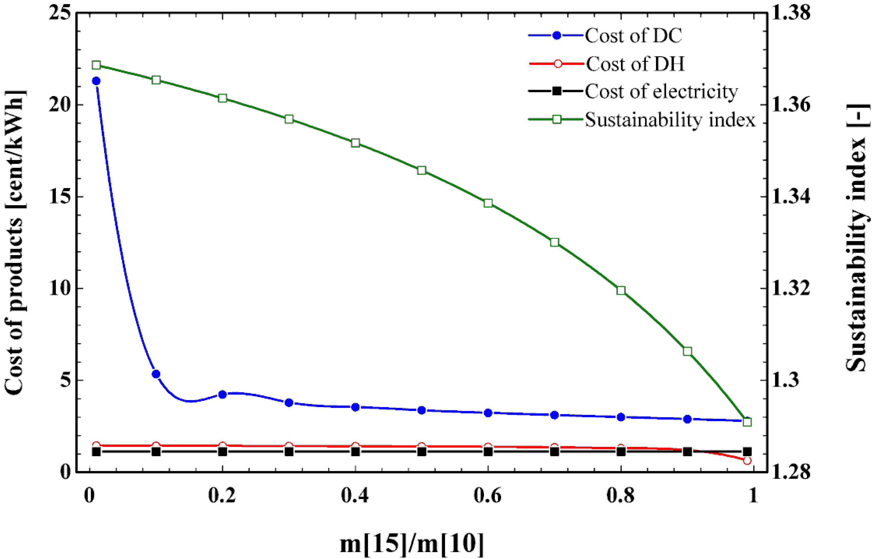
  • Under the base condition, half of the pressurized hot water (point 10 in Figure 1) is utilized to drive the chiller, while the rest is used to heat the water and provide district heating.

3. Thermodynamic, Economic, and Environmental Models

3.1. Thermodynamic Analysis

In this section, the proposed system is analyzed from the first law perspective. The thermal behavior of the whole system and employed components are evaluated in detail and thermodynamic equations are applied for each unit, separately, including mass balance and energy conservation. For this reason, each component is hypothesized to be an individual control volume. Generic equations are as follows [25]:
m ˙ i = m ˙ o
m ˙ i h i + Q ˙ = m ˙ o h o + W ˙
Considering the whole system’s energetic performance, products of the system are supplied district heating ( Q ˙ D H ), district cooling ( Q ˙ D C ), and power ( W ˙ n e t ). Then, the thermal or first law efficiency of the system can be written as:
η I = Q ˙ D H + Q ˙ D C + W ˙ n e t m ˙ 1 L H V M W
where,
Q ˙ D H = m ˙ 37 ( h 38 h 37 ) + m ˙ 33 ( h 34 h 33 )
Q ˙ D C = m ˙ 27 ( h 27 h 28 )
W ˙ n e t = W ˙ S T W ˙ P 1 W ˙ P 2 W ˙ P 3
Besides, fuel-to-power, fuel-to-heat, and fuel-to-cold efficiencies can be written as:
η F P = W ˙ n e t m ˙ 1 L H V M W
η F H = Q ˙ D H m ˙ 1 L H V M W
η F C = Q ˙ D C m ˙ 1 L H V M W
Although energy analysis clears the value of supplying energy in terms of heating, cooling, and electricity, it does not give a clear picture of system inefficiency and destruction [26]. Therefore, exergy analysis is performed to evaluate the whole thermodynamic performance of the system. Unlike the energy principle (known as energy conservation), exergy may be destroyed during each real thermodynamic process and is not conserved within the system components [27]. Besides, exergy analysis clarifies the exact value and location of irreversibilities within the designed plant, which is important from the sustainability aspect [28].
Since the changes in elevation and speed are ignored, the change of the potential and kinetic exergies are neglected and only two main parts remain: physical and chemical exergies. Physical or thermomechanical exergy depends on the ambient and streams’ condition [20]:
e p h = h i h 0 T 0 ( s i s 0 )
Combustion process within the incinerator results in a change in the compositions and that is why the chemical exergy should be considered in this study. Chemical exergy depends on several factors, like the molar composition of each element in the mixture and is defined as [29]:
e m i x t u r e c h = i n i e 0 , i c h + R ¯ T 0 n i ln x i
After defining the specific thermomechanical and chemical exergy in each state, the exergy rate associated with the ith stream can be written as [30,31]:
E ˙ i = m ˙ i ( e i p h + e i c h )
After calculating the exergy rate related to each stream, each component is considered to be an individual unit to adopt the exergy balance equation as follows [32]:
E ˙ i + Q ˙ c v ( 1 T 0 T K ) = W ˙ c v + E ˙ o + E ˙ D
here, E ˙ i is the summation of inlet exergy rates to the considered control volume (each component), Q ˙ c v ( 1 T 0 T K ) is the amount of exergy in conjunction with passed overheat, E ˙ o is the summation of outlet exergy rates, and E ˙ D is the irreversibility (exergy destruction) within the control volume. It should be noticed that part of the irreversibility is due to exergy losses within the system like discharged exergy to the atmosphere via exhaust gasses or coolant water without any further usage, while the rest is because of thermodynamic irreversibilities [33].
The exergy value associated with different terms of energy determines the entire system exergetic or second law efficiency, as follows [14,20]:
η I I , t o t a l = W ˙ n e t + E ˙ D H + E ˙ D C E ˙ M W
here,
E ˙ D H = E ˙ 38 E ˙ 37 + E ˙ 34 E ˙ 33
E ˙ D C = E ˙ 27 E ˙ 28
Estimating the chemical exergy rate of the municipal waste ( E ˙ M W ) is described in detail in [34].

3.2. Economic Analysis

In this section, specific exergy costing method (SPECO) is utilized to assess the economic performance of the system. This method is known as the exergoeconomic analysis which is developed by Tsatsaronic et al. [35]. In fact, exergoeconomic combines the exergy and economic principles, which results in valuable data not accessible via thermodynamic analysis and economic evaluating, separately. In this way, economic effectiveness can be considered as an index for different energy systems. Typically, the exergoeconomic examination of energy systems is based on the following main steps:
  • Defining the value of energy and exergy at each state point.
This step has been done via thermodynamic assessment of the system. In fact, thermodynamic evaluation is the prerequisite of exergoeconomic analysis.
  • Adopting cost balance equations.
In the traditional economic evaluation, cost balance is typically expressed for the entire system. This is while in the exergoeconomic analysis this equation is formulated for each component of the system. In this way, it is possible to obtain the cost of fuel and products considering economic value for each unit of exergy, which assists designers with information regarding the cost of irreversibilities in different locations [36]. Cost balance equation states that sum of the expenditure related to the inlet stream to a considered control volume as well as the cost rate associated with the capital investment is equal to the cost of products coming out from the control volume [37]. A comprehensive explanation of exergoeconomic analysis can be found in [37]. This equation is adopted for the employed components in the proposed CCHP system, as follows:
C ˙ e , k + C ˙ w , k = C ˙ q , k + C ˙ i , k + Z ˙ k
here,
C ˙ = c E ˙
where, C ˙ is the cost rates associated with each exergy flow and c is the unit cost of exergy. Besides, Z ˙ k is the levelized cost of the kth component which is obtained as follows [38]:
Z ˙ = Z × C R F × ϕ 3600 N
in which, Z, CRF, N, and ϕ are capital investment cost of components in terms of dollar, capital recovery factor, system operating hour in each year (7446 h, due to capacity factor of 85%) and maintenance factor (6%), respectively [37]. Capital costs of components employed in the present municipal waste-driven CCHP are taken from the literature [12,36,37,39,40], and related cost functions are listed in Table 2.
One of the main indicators of the exergoeconomic analysis is the exergoeconomic factor, which compares the cost related to the capital cost of the component with that of related to the exergy destruction within the component. Accordingly, the exergoeconomic factor provides some useful data regarding the replacement of components with better exergetic performance or lower purchasing cost at the expense of higher exergy destruction.
f = Z ˙ k Z ˙ k + C ˙ D , k
To obtain the payback period of the presented CCHP system, net present value (NPV) technique is adopted. The formula to calculate the NPV of each cash flow is as follows [37]:
N P V = n = 0 B L Y n ( 1 + i ) n
In this equation, Yn is the net cash flow (income or expenditure) at the end of the nth time period. It is worthy of mentioning that the salvage value of the plant is ignored.

3.3. Environmental Analysis

To design a cogeneration system, not only thermodynamic and economic aspects should be considered, but also specific attention should be paid to the sustainability and environmental aspects. Hereunder, exergoeconomic analysis and sustainability index are utilized to investigate the proposed municipal waste-driven CCHP system from the environment and sustainability points of view. Emitted CO2 and NOx from the waste combustion process are considered as the main pollutants existing in the effluent. The first one can be directly obtained from the component balance during the combustion procedure and the latter can be calculated using the following equation [41]:
m N O x = 0.15 × 10 16 × τ 0.5 exp ( 71,100 T P Z ) P c o m b 0.05 ( Δ P c o m b P c o m b ) 0.5
The equation above gives the released NOx to the atmosphere in terms of gram per each kg of solid waste. τ is supposed to be 0.002 s as the residence time in combustion zone, combustion flame temperature is shown with T P Z and subscribe comb refers to the combustion. Cost rate related to the environmental impact is added to the other costs of the system and can be written as [42]:
C ˙ e n v = c C O 2 m ˙ C O 2 + c N O x m ˙ N O x
where, c C O 2 and c N O x are supposed to be 2.4 cent/kg and 685.3 cent/kg, respectively [43].
On the other hand, sustainable development requires not only that sustainable energy resources be used, but also the resources should be used efficiently [44]. Consequently, in this way, it is possible to reduce the usage of limited energy sources and to extend their lifespans. Sustainability index, which makes a relationship between the second law analysis and the environmental impact, is as follows [45]:
S I = 1 D P
where, D P is a depletion number and can be calculated as the total destroyed exergy divided by input exergy.

4. Results and Discussions

The results associated with the system simulation are presented and discussed in this section. Proposed municipal waste-driven CCHP is simulated via developing a computer program utilizing EES (engineering equation solver) software [46]. Thermophysical properties, mass flow rate, and stream composition of each flow are listed in Table 3. This table is of significant importance to check the applied thermodynamic principles and check the performance of the different heat exchangers employed in the proposed CCHP. State 3 in this table refers to the combustion products within the incinerator and was not shown in Figure 1.
Exergy flow diagram of the cogeneration plant is shown in Figure 2. This figure points out the exergy values of different streams under the base condition (half of the pressurized heated water is used to cooling production unit and the residue is utilized to deliver heating). As it was predictable, a considerable value of exergy destruction occurs in the incinerator mainly because of the combustion procedure. In this figure, the absorption chiller is considered as a unit component and causes the second highest exergy destruction. The exergy rates associated with the products are depicted in this figure in terms of electricity (2937 kW), district heating supplied via HE4 (86.2-10.9 kW), district heating supplied via HE2 (721.1-91 kW), and district cooling supplied via absorption chiller (83.2 kW).
The portion of each main section in the total required purchasing cost as the capital investment is shown in Figure 3. Definitely, the most expensive components will affect the cost effectiveness of the plant and the cost of products as well. According to this figure, the costliest unit is the employed incinerator equipped with a steam boiler, which causes almost 79% of the total required expenditures. The second important unit from the capital investment cost point of view is the steam turbine and 11% of the total needed cost refers to this component. However, it should be noted that the cost related to the waste furnace, cost of the steam generator, and the cost of the emission control unit are taken into account in determining the cost of the incinerator unit [12].
The technical specifications obtained from the proposed waste-fired modeling resulting from both thermodynamic and economic assessments are listed in Table 4. Results reported in this table are gained under the base condition. It is worth mentioning that the technical parameters related to the system performance are not a function of the system maximum capacity. Therefore, the electrical capacity equal to the produced power from incineration 1 kg/s of the municipal waste (resulting in 2904 kWe) is considered. Furthermore, off-design analysis was not performed in this study. Though this causes uncertainty in the modeling compared to a real CCHP, it still might be sensible for the presented municipal waste-fired CCHP plant. The first reason to support this idea is that these kinds of multi-generation systems are utilized for base-load coverage, working under the full load condition [47]. The second reason is that the operation load does not affect the performance degradation of a power plant linearly [48]. Thermodynamic analysis revealed that incinerating 1 kg/s of municipal solid waste resulted in thermal, exergetic, fuel-to-power, fuel-to-heat, and fuel-to-cold efficiencies of 83.28, 25.69, 23.49, 47.41, and 12.38%, respectively. As can be seen, fuel-to-power efficiency has a value close to the second law efficiency. This is because the exergy rates associated with thermal loads (supplied heating and cooling) are much lower than the electrical load transferred to the main grid. The total capital investment cost of 6.501 million USD was estimated to be for the whole designed CCHP system. Maintenance cost was also included in this value. However, the reported cost refers to the basic operating condition and changing operating conditions would change the capital cost, mainly because of variation in the size of the employed components. Besides, the unit cost of supplied power is estimated to be 1.129 cent/kWh (3.135 $/GJ) via applying exergoeconomic principle which is completely comparable with that of reported in the literature [12]. In addition, the unit cost of produced heating and cooling are obtained to be 1.407, 3.374 cent/kWh, respectively. Furthermore, the cost rate related to the environmental impact was 158.9 $ per hour, considering environmental degradation associated with CO2 and NOx as the main emissions. Moreover, the sustainability index of 1.346 confirms the high value of environmental degradation cost.
One of the main economic indices to show the cost effectiveness of the newly developed energy systems is the payback period. To determine the payback period of the proposed CCHP system NPV method is utilized. Figure 4 represents the net present value for the first 10 years of the system operation. According to this figure, the payback period of almost 6 years would recover the costs associated with the whole system. Cost of fuel for the presented system was the cost of municipal solid waste and was hypothesized to be zero based on Aghbashloo et al. [5].
The main exergetic and economic parameters calculated for the proposed cogeneration plant are sketched in Table 5. In this table, components are ranked in descending order of cost importance using the amount of the capital investment cost plus cost of destroyed exergy ( Z ˙ k + C ˙ D , k ) based on Bejan et al. [37]. As was expected, the maximum value of Z ˙ k + C ˙ D , k fits to the incinerator equipped with a boiler zone which has an exergoeconomic factor of 33.38%. This value of Z ˙ k + C ˙ D , k clarifies the exergoeconomic importance of this unit and much attention should be paid on this component to enhance the total economic performance of the system. Destroyed exergy cost of 84.05 $/h and low value of exergoeconomic factor states that the cost rate associated with destroyed exergy is higher than the cost rate associated with the capital investment and maintenance. However, as it is clear, no considerable effort can be made to improve the incinerator performance as all the irreversibility sources, i.e., combustion, temperature difference, and mixing are present within this unit [49]. Nevertheless, suggesting some limited enhancements like preheating the inlet air can be found in the literature. The second main unit from the exergoeconomic point of view is the employed steam turbine with the f value of 72.74% and exergy efficiency of 91.81%. This f value indicates that the purchasing cost of this component is higher than the cost of the destroyed exergy within this unit. Hence, replacement with a cheaper turbine is advised at the expense of the second law efficiency. The involved absorber in the chiller unit is the third important unit with the lowest f value, among the all. Exergoeconomic factor of 2.88% indicates that the cost of destroyed exergy is thoroughly dominant compared to the capital investment cost, and low value of exergy efficiency (6.91%) confirms this fact. It can be stated that improving the exergetic performance of the absorber at the expense of higher purchasing cost enhances the CCHP economic performance significantly. Opposite to the absorber, heat exchanger 4 operates with the highest value of exergoeconomic factor. In fact, 80.42% of the cost rate related to this component is in conjunction with the capital cost and less than 20% is due to exergy destruction within this unit.
Meanwhile, it should be pointed out that the exergetic and exergoeconomic performance of each component may be deteriorated by improving the performance of each individual component. Then, the recommendations prepared to improve the economic performance of each component does not essentially mean an enhanced performance for the entire proposed waste-fired CCHP system.
To make the obtained outcomes more generalized, the effect of chiller supply on the system performance is examined. Figure 5 illustrates changes in the cost of products and sustainability index with varying chiller supply. Though the unit cost of electricity and district heating are not impacted significantly, increasing chiller supply decreases the unit cost of district cooling. Power production via steam turbine is not affected by the change in the chiller supply rate and harvested heat from power producing block is fed to generate heating and cooling. This is also the same for heat production through waste heat recovery procedure.
As can be seen, in lover values of m ˙ 15 m ˙ 10 , change in the cooling cost is intense. The unit cost of supplied cooling is a complex function of the chiller unit capital cost and cost of harvested heat from the steam cycle. However, to explain this, it should be pointed out that in lover values of chiller supply, the rate of delivering district cooling is low, while the capital cost of the chiller unit is considered. On the other hand, increasing chiller supply causes a reduction in the sustainability index of the whole CCHP. This is because the exergy rate associated with the delivered heat (warm pressurized water) is much higher than that of delivered cool (chilled water). Therefore, supplying higher values of district heating rather than cooling is encouraging from the sustainability point of view. Changing chiller supply rate from 0.01 to 0.99 results in decrease in the sustainability index from 1.369 to 1.291 and decreases the unit cost of cooling from 21.93 to 2.795 cent/kWh.

5. Conclusions

A municipal waste-driven CCHP was presented and evaluated via technical, economic, and environmental principles. The proposed system consisted of a conventional heat and power generation system with a large-scale LiBr/H2O absorption chiller, which utilized the waste heat content of the effluent. This system was designed to deliver the energy demands of a neighborhood. Produced power was considered as the electricity supply, while generated heat and cool was supposed to be supplied as the heating and cooling demand of the neighborhood. SPECO method was adopted to evaluate the exergy-based economic performance of the system. In this way, the unit cost of products in terms of power, heating, and cooling were estimated. Also, exergoeconomic performance of the individual components employed in the system was examined. The main findings of the present study under the base condition (where half of the harvested heat from the steam power cycle was utilized to run the chiller) are as follows:
  • Thermal, exergetic, fuel-to-power, fuel-to-heat, and fuel-to-cold efficiencies were found to be 83.28, 25.69, 23.49, 47.41, and 12.38%, respectively.
  • The most expensive component in the system was the employed incinerator equipped with a steam boiler followed by steam turbine causing 79 and 11% of total capital investment cost, respectively.
  • The unit costs of supplied power, heat, and cool were found to be 1.129, 1.407, and 3.374 cent/kWh, respectively, while the cost rate associated with the environmental impact was 158.9 $ per hour.
  • The highest value of Z ˙ k + C ˙ D , k referred to the incinerator with an exergy destruction cost of 84.05 $ per hour.
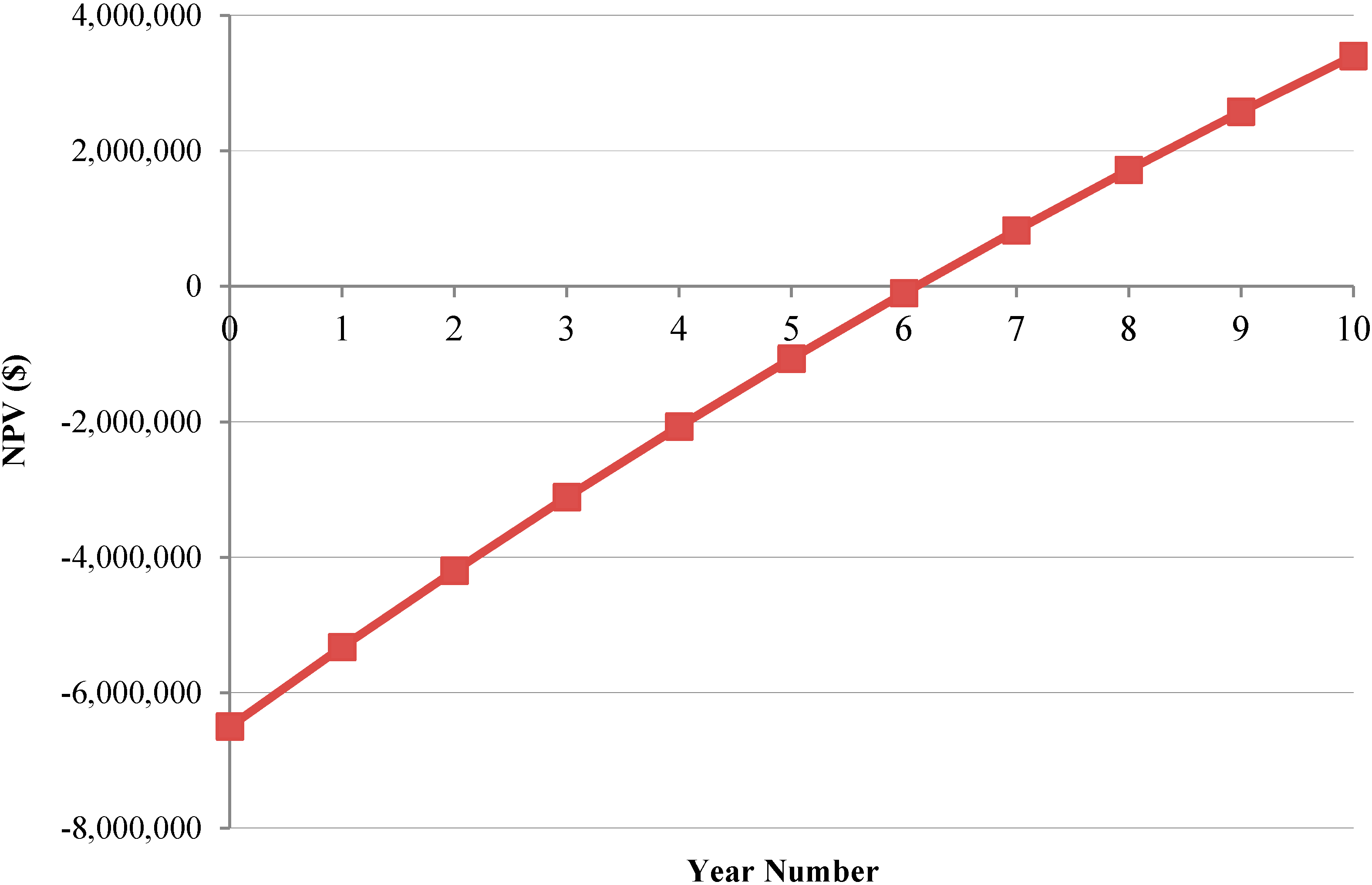
  • The total capital investment cost of $6.501 million was estimated for the system, while the payback period of 6 years was obtained based on the NPV method.

Author Contributions

Conceptualization, A.A. and H.N.; methodology, H.N.; software, H.N.; formal analysis, H.N.; investigation, H.N.; writing—original draft preparation, A.A.-M.; writing—review and editing, A.A.-M. and A.A.; supervision, A.A.-M.; project administration, A.A.-M.; funding acquisition, A.A.-M. All authors have read and agreed to the published version of the manuscript.

Funding

This research is part of the “HeatReFlex-Green and Flexible District Heating/Cooling” project (www.heatreflex.et.aau.dk) funded by Danida Fellowship Centre and the Ministry of Foreign Affairs of Denmark to conduct research in growth and transition countries under the grant no. 18-M06-AAU.

Conflicts of Interest

The authors declare no conflict of interest.

Nomenclature

Abbreviations
Absabsorber
CCHPcombined cooling, heating and power
CHPcombined heat and power
Condcondenser
COPcoefficient of performance
CRFcapital recovery factor
DCdistrict cooling
DHdistrict heating
Evaevaporator
FWTfeed water tank
Gengenerator
HEheat exchanger
Incinincinerator
LHVlover heating value
MWmunicipal waste
MSWmunicipal solid waste
NPVnet present value
Ppump
SHEsolution heat exchanger
SIsustainability index
STsteam turbine
Latin letters
cunit cost of exergy ($/GJ)
C ˙ cost rate ($/s)
Dpdepletion number
e specific physical exergy (J/kg)
E ˙ exergy flow rate (W)
fexergoeconomic factor (%)
hspecific enthalpy (J/kg)
m ˙ mass flow rate (kg/s)
Nnumber of operating hours per year
PPressure (bar)
Q ˙ heat transfer rate (W)
Rgas constant (J/kg K)
sentropy (J/kg K)
Ttemperature (K)
W ˙ power (W)
Zcapital investment cost ($)
Z ˙ levelized capital investment cost ($/s)
Greek letters
η I energy (thermal) efficiency (-)
η I I exergy efficiency (-)
η F P Fuel-to-power efficiency (-)
η F H Fuel-to-heat efficiency (-)
η F C Fuel-to-cold efficiency (-)
ϕ maintenance factor
τ residence time in combustion zone (s)
Subscripts
cvcontrol volume
Ddestruction
Ffuel
i & ininlet conditions
isisentropic
ooutlet
outoutlet conditions
Pproduct
phphysical
0ambient conditions

References

  1. Arabkoohsar, A.; Gharahchomaghloo, Z.; Farzaneh-Gord, M.; Koury, R.N.N.; Deymi-Dashtebayaz, M. An energetic and economic analysis of power productive gas expansion stations for employing combined heat and power. Energy 2017, 133, 737–748. [Google Scholar] [CrossRef]
  2. Lund, H.; Østergaard, P.A.; Connolly, D.; Mathiesen, B.V. Smart energy and smart energy systems. Energy 2017, 137, 556–565. [Google Scholar] [CrossRef]
  3. AlSagri, A.S.; Arabkoohsar, A.; Rahbari, H.R.; Alrobaian, A.A. Partial Load Operation Analysis of Trigeneration Subcooled Compressed Air Energy Storage System. J. Clean. Prod. 2019, 238, 117948. [Google Scholar] [CrossRef]
  4. Arabkoohsar, A.; Andresen, G. Design and optimization of a novel system for trigeneration. Energy 2019, 168, 247–260. [Google Scholar] [CrossRef]
  5. Aghbashlo, M.; Tabatabaei, M.; Soltanian, S.; Ghanavati, H.; Dadak, A. Comprehensive exergoeconomic analysis of a municipal solid waste digestion plant equipped with a biogas genset. Waste Manag. 2019, 87, 485–498. [Google Scholar] [CrossRef]
  6. Yang, K.; Zhu, N.; Ding, Y.; Chang, C.; Wang, D.; Yuan, T. Exergy and exergoeconomic analyses of a combined cooling, heating, and power (CCHP) system based on dual-fuel of biomass and natural gas. J. Clean. Prod. 2019, 206, 893–906. [Google Scholar] [CrossRef]
  7. Wang, J.; Lu, Z.; Li, M.; Lior, N.; Li, W. Energy, exergy, exergoeconomic and environmental (4E) analysis of a distributed generation solar-assisted CCHP (combined cooling, heating and power) gas turbine system. Energy 2019, 175, 1246–1258. [Google Scholar] [CrossRef]
  8. Owebor, K.; Oko, C.; Diemuodeke, E.; Ogorure, O. Thermo-environmental and economic analysis of an integrated municipal waste-to-energy solid oxide fuel cell, gas-, steam-, organic fluid- and absorption refrigeration cycle thermal power plants. Appl. Energy 2019, 239, 1385–1401. [Google Scholar] [CrossRef]
  9. Wu, J.; Wang, J.; Wang, J.; Ma, C. Exergy and Exergoeconomic Analysis of a Combined Cooling, Heating, and Power System Based on Solar Thermal Biomass Gasification. Energies 2019, 12, 2418. [Google Scholar] [CrossRef] [Green Version]
  10. Yang, Y.; Wang, J.; Chong, K.; Bridgwater, A.V. A techno-economic analysis of energy recovery from organic fraction of municipal solid waste (MSW) by an integrated intermediate pyrolysis and combined heat and power (CHP) plant. Energy Convers. Manag. 2018, 174, 406–416. [Google Scholar] [CrossRef] [Green Version]
  11. Yari, M.; Mehr, A.S.; Mahmoudi, S.M.S.; Santarelli, M. A comparative study of two SOFC based cogeneration systems fed by municipal solid waste by means of either the gasifier or digester. Energy 2016, 114, 586–602. [Google Scholar] [CrossRef]
  12. Jack, T.A.; Oko, C.O.C. Exergy and exergoeconomic analysis of a municipal waste-to-energy steam reheat power plant for Port Harcourt city. Int. J. Ambient Energy 2018, 39, 352–359. [Google Scholar] [CrossRef]
  13. Nami, H.; Anvari-Moghaddam, A. Small-scale CCHP systems for waste heat recovery from cement plants: Thermodynamic, sustainability and economic implications. Energy 2020, 192, 116634. [Google Scholar] [CrossRef]
  14. Nami, H.; Arabkoohsar, A.; Anvari-Moghaddam, A. Thermodynamic and sustainability analysis of a municipal waste-driven combined cooling, heating and power (CCHP) plant. Energy Convers. Manag. 2019, 201, 112158. [Google Scholar] [CrossRef]
  15. Solheimslid, T.; Harneshaug, H.K.; Lümmen, N. Calculation of first-law and second-law-efficiency of a Norwegian combined heat and power facility driven by municipal waste incineration–A case study. Energy Convers. Manag. 2015, 95, 149–159. [Google Scholar] [CrossRef]
  16. Arabkoohsar, A.; Nami, H. Thermodynamic and economic analyses of a hybrid waste-driven CHP–ORC plant with exhaust heat recovery. Energy Convers. Manag. 2019, 187, 512–522. [Google Scholar] [CrossRef]
  17. Nami, H.; Arabkoohsar, A. Improving the power share of waste-driven CHP plants via parallelization with a small-scale Rankine cycle, a thermodynamic analysis. Energy 2019, 171, 27–36. [Google Scholar] [CrossRef]
  18. Razmi, A.R.; Soltani, M.; Kashkooli, F.M.; Garousi Farshi, L. Energy and exergy analysis of an environmentally-friendly hybrid absorption/recompression refrigeration system. Energy Convers. Manag. 2018, 164, 59–69. [Google Scholar] [CrossRef]
  19. Tabasová, A.; Kropáč, J.; Kermes, V.; Nemet, A.; Stehlik, P. Waste-to-energy technologies: Impact on environment. Energy 2012, 44, 146–155. [Google Scholar] [CrossRef]
  20. Nami, H.; Ertesvåg, I.S.; Agromayor, R.; Riboldi, L.; Nord, L.O. Gas turbine exhaust gas heat recovery by organic Rankine cycles (ORC) for offshore combined heat and power applications-Energy and exergy analysis. Energy 2018, 165, 1060–1071. [Google Scholar] [CrossRef]
  21. Ahmadi, P.; Almaši, A.; Shahriyari, M.; Dincer, I. Multi-objective optimization of a combined heat and power (CHP) system for heating purpose in a paper mill using evolutionary algorithm. Int. J. Energy Res. 2012, 36, 46–63. [Google Scholar] [CrossRef]
  22. Persson, U.; Münster, M. Current and future prospects for heat recovery from waste in European district heating systems: A literature and data review. Energy 2016, 110, 116–128. [Google Scholar] [CrossRef] [Green Version]
  23. Inayat, A.; Raza, M. District cooling system via renewable energy sources: A review. Renew. Sustain. Energy Rev. 2019, 107, 360–373. [Google Scholar] [CrossRef]
  24. Razmi, A.R.; Soltani, M.; Torabi, M. Investigation of an efficient and environmentally-friendly CCHP system based on CAES, ORC and compression-absorption refrigeration cycle: Energy and exergy analysis. Energy Convers. Manag. 2019, 195, 1199–1211. [Google Scholar] [CrossRef]
  25. Ahmadi, P.; Dincer, I.; Rosen, M.A. Exergo-environmental analysis of an integrated organic Rankine cycle for trigeneration. Energy Convers. Manag. 2012, 64, 447–453. [Google Scholar] [CrossRef]
  26. Voldsund, M.; Ertesvåg, I.S.; He, W.; Kjelstrup, S. Exergy analysis of the oil and gas processing on a north sea oil platform a real production day. Energy 2013, 55, 716–727. [Google Scholar] [CrossRef]
  27. Szargut, J.; Morris, D.R.; Steward, F.R. Exergy Analysis of Thermal, Chemical, and Metallurgical Processes; Hemisphere: Philadelphia, PA, USA, 1988. [Google Scholar]
  28. Cengel, Y.A.; Boles, M.A. Thermodynamics: An Engineering Approach, 6th ed.; McGraw-Hill: New York, NY, USA, 2007. [Google Scholar]
  29. Razmi, A.R.; Soltani, M.; Tayefeh, M.; Torabi, M.; Dusseault, M.B. Thermodynamic analysis of compressed air energy storage (CAES) hybridized with a multi-effect desalination (MED) system. Energy Convers. Manag. 2019, 199, 112047. [Google Scholar] [CrossRef]
  30. Razmi, A.R.; Janbaz, M. Exergoeconomic assessment with reliability consideration of a green cogeneration system based on compressed air energy storage (CAES). Energy Convers. Manag. 2020, 204, 112320. [Google Scholar] [CrossRef]
  31. Nemati, A.; Nami, H.; Yari, M.; Ranjbar, F. Effect of geometry and applied currents on the exergy and exergoeconomic performance of a two-stage cascaded thermoelectric cooler. Int. J. Refrig. 2018, 85, 1–12. [Google Scholar] [CrossRef]
  32. Nemati, A.; Nami, H.; Yari, M.; Ranjbar, F. Methanol synthesis from renewable H2 and captured CO2 from S-Graz cycle–Energy, exergy, exergoeconomic and exergoenvironmental (4E) analysis. Int. J. Hydrogen Energy 2019, 44, 26128–26147. [Google Scholar]
  33. Mohammadkhani, F.; Ranjbar, F.; Yari, M. A comparative study on the ammonia-water based bottoming power cycles: The exergoeconomic viewpoint. Energy 2015, 87, 425–434. [Google Scholar] [CrossRef]
  34. Song, G.; Shen, L.; Xiao, J. Estimating Specific Chemical Exergy of Biomass from Basic Analysis Data. Ind. Eng. Chem. Res. 2011, 50, 9758–9766. [Google Scholar] [CrossRef]
  35. Tsatsaronis, G.; Lin, L.; Pisa, J. Exergy Costing in Exergoeconomics. J. Energy Resour. Technol. 1993, 115, 9. [Google Scholar] [CrossRef]
  36. Baghernejad, A.; Yaghoubi, M. Exergoeconomic analysis and optimization of an Integrated Solar Combined Cycle System (ISCCS) using genetic algorithm. Energy Convers. Manag. 2011, 52, 2193–2203. [Google Scholar] [CrossRef]
  37. Bejan, A.; Tsatsaronis, G. Thermal Design and Optimization; John Wiley & Sons: Hoboken, NJ, USA, 1996. [Google Scholar]
  38. Razmi, A.R.; Soltani, M.; Aghanajafi, C.; Torabi, M. Thermodynamic and economic investigation of a novel integration of the absorption-recompression refrigeration system with compressed air energy storage (CAES). Energy Convers. Manag. 2019, 187, 262–273. [Google Scholar] [CrossRef]
  39. Fei, F.; Wen, Z.; Huang, S.; De Clercq, D. Mechanical biological treatment of municipal solid waste: Energy efficiency, environmental impact and economic feasibility analysis. J. Clean. Prod. 2018, 178, 731–739. [Google Scholar] [CrossRef]
  40. Mohammadkhani, F.; Yari, M.; Ranjbar, F. A zero-dimensional model for simulation of a Diesel engine and exergoeconomic analysis of waste heat recovery from its exhaust and coolant employing a high-temperature Kalina cycle. Energy Convers. Manag. 2019, 198, 111782. [Google Scholar] [CrossRef]
  41. Ahmadi, P.; Rosen, M.A.; Dincer, I. Greenhouse gas emission and exergo-environmental analyses of a trigeneration energy system. Int. J. Greenh. Gas Control. 2011, 5, 1540–1549. [Google Scholar] [CrossRef]
  42. Khaljani, M.; Saray, R.K.; Bahlouli, K. Comprehensive analysis of energy, exergy and exergo-economic of cogeneration of heat and power in a combined gas turbine and organic Rankine cycle. Energy Convers. Manag. 2015, 97, 154–165. [Google Scholar] [CrossRef]
  43. Ahmadi, P.; Dincer, I. Exergoenvironmental analysis and optimization of a cogeneration plant system using Multimodal Genetic Algorithm (MGA). Energy 2010, 35, 5161–5172. [Google Scholar] [CrossRef]
  44. Dincer, I.; Hussain, M.; Al-Zaharnah, I. Energy and exergy use in the industrial sector of Saudi Arabia. Proc. Inst. Mech. Eng. Part A J. Power Energy. 2003, 217, 481–492. [Google Scholar] [CrossRef]
  45. Nami, H.; Ranjbar, F.; Yari, M. Thermodynamic assessment of zero-emission power, hydrogen and methanol production using captured CO 2 from S-Graz oxy-fuel cycle and renewable hydrogen. Energy Convers. Manag. 2018, 161, 53–65. [Google Scholar] [CrossRef]
  46. Klein, S.A.; Alvarado, F.L. Engineering Equation Solver; F-Chart software: Madison, WI, USA, 2002. [Google Scholar]
  47. Arabkoohsar, A.; Andresen, G.B. A smart combination of a solar assisted absorption chiller and a power productive gas expansion unit for cogeneration of power and cooling. Renew. Energy 2018, 115, 489–500. [Google Scholar] [CrossRef]
  48. Savola, T.; Keppo, I. Off-design simulation and mathematical modeling of small-scale CHP plants at part loads. Appl. Therm. Eng. 2005, 25, 1219–1232. [Google Scholar] [CrossRef]
  49. Bejan, A. Advanced Engineering Thermodynamics; John Wiley & Sons: Hoboken, NJ, USA, 2016. [Google Scholar]
Figure 1. Flow diagram of the proposed municipal waste-fired CCHP (MSW: municipal solid waste; Incin: incinerator; P: pump; ST: steam turbine; FWT: feed water tank; HE: heat exchanger; SHE: solution heat exchanger; Abs: absorber; Gen: generator; Eva: evaporator.).
Energies 13 02476 g001
Figure 2. Exergy flow diagram of the proposed CCHP system.
Energies 13 02476 g002
Figure 3. Investment capital breakdown of the proposed CCHP.
Energies 13 02476 g003
Figure 4. Net present value (NPV) of the economic performance of the proposed CCHP for 10 years operation.
Energies 13 02476 g004
Figure 5. Effect of the chiller supply on the system performance.
Energies 13 02476 g005
Table 1. Data utilized for municipal waste and waste incineration unit [12].
ParameterValue
Lower heating value of the waste (kJ/kg)12,500
Excess air required for the combustion process80%
Temperature of the combustion products (K)1373
Waste compositions (weight percent)0.0591 Ash
0.4718 Carbon
0.0625 Hydrogen
0.3957 Oxygen
0.0091 Nitrogen
0.0018 Sulphur
Table 2. Cost functions of the proposed CCHP components [12,36,37,39,40].
ComponentCost Function
Incin Z I n c i n = 275.8 m ˙ m w + 18,231,500
ST Z S T = 6000 W ˙ S T 0.6
P1 Z P 1 = 3540 W ˙ P 1
P2 Z P 2 = 3540 W ˙ P 2
P3 Z P 3 = 3540 W ˙ P 3
Gen Z G e n = 17,500 ( A G e n / 100 ) 0.6
Abs Z A b s = 16,000 ( A A b s / 100 ) 0.6
Eva Z E v a = 16,000 ( A E v a / 100 ) 0.6
SHE Z S H E = 12,000 ( A S H E / 100 ) 0.6
Cond Z C o n d = 8000 ( A C o n d / 100 ) 0.6
HE1 Z E v a = 309.14 A H E 1 0.85
HE2 Z H E 2 = 309.14 A H E 2 0.85
HE3 Z H E 3 = 7000 + 360 A H E 3 0.8
HE4 Z H E 4 = 7000 + 360 A H E 4 0.8
Table 3. Thermodynamic and economic properties in each state point of the proposed CCHP.
State No.T (K)P (bar)Stream Compositions Mass Flow Rate (kg/s)
1293.21.01See Table 11
2293.21.01N2, O2 8.56, 2.60
310941.01N2, CO2, O2, H2O, SO28.5667, 1.8386, 1.1576, 0.5941, 0.0039
44381.01N2, CO2, O2, H2O, SO28.5667, 1.8386, 1.1576, 0.5941, 0.0039
5823.2100H2O2.98
6364.70.7438H2O2.98
7364.70.7438H2O2.98
8364.70.7438H2O2.98
9365.5100H2O2.98
10359.75.614H2O59.49
11363.25.614H2O29.74
12320.75.614H2O29.74
13320.75.614H2O29.74
14334.25.614H2O59.49
15363.25.614H2O29.74
16347.85.614H2O29.74
17308.20.008726LiBr-H2O solution (X= 0.5528)7.892
18308.20.05627LiBr-H2O solution (X= 0.5528)7.892
19342.80.05627LiBr-H2O solution (X= 0.5528)7.892
20353.20.05627LiBr-H2O solution (X= 0.6028)7.237
21312.70.05627LiBr-H2O solution (X= 0.6028)7.237
22312.70.008726LiBr-H2O solution (X= 0.6028)7.237
23308.20.05627H2O0.6546
24278.20.008726H2O0.6546
25278.20.008726H2O0.6546
26353.20.05627H2O0.6546
27283.21.01H2O123.1
28280.21.01H2O123.1
29293.21.01H2O78.34
30298.21.01H2O78.34
31293.21.01H2O5.313
32298.21.01H2O5.313
33313.22.474H2O31.63
34353.22.474H2O31.63
35371.51.01N2, CO2, O2, H2O, SO28.5667, 1.8386, 1.1576, 0.5941, 0.0039
36321.91.01N2, CO2, O2, H2O, SO28.5667, 1.8386, 1.1576, 0.5941, 0.0039
37313.22.474H2O3.78
38353.22.474H2O3.78
Table 4. Technical features obtained from simulation of the proposed municipal waste-driven CCHP system under the base condition.
Parameter (Unit)Value
Thermal efficiency (%)83.28
Exergy efficiency (%)25.69
Fuel-to-power efficiency (%)23.49
Fuel-to- heat efficiency (%)47.41
Fuel-to-cold efficiency (%)12.38
COP of the absorption chiller (-)0.8057
Net produced power (kW)2904
Delivered district heating (kW)5926
Delivered district cooling (kW)1547
Total capital investment cost ( million $)6.501
Unit cost of generated power (cent/kWh)1.129
Unit cost of delivered heating (cent/kWh)1.407
Unit cost of delivered cooling (cent/kWh)3.374
Cost of environmental impact ($/h)158.9
Sustainability index (-)1.346
Table 5. Thermodynamic and economic main parameters of the proposed waste-fired CCHP system components.
Units E ˙ F ( kW ) E ˙ P ( kW ) E ˙ D ( kW ) η I I ( % ) C ˙ D ( $ / h ) Z ˙ ( $ / h ) Z ˙ + C ˙ D ( $ / h ) f ( % )
Incin1442344151000830.6184.0542.12126.1733.38
ST3199293726291.812.2295.9488.17772.74
Abs93.726.47487.2466.915.0390.14945.18842.88
Cond83.2913.8269.4716.593.9271.1435.0722.55
HE11247983.2263.878.842.240.86833.108327.93
Gen336.396.58239.7228.722.7180.3653.08311.84
HE2749.2630.1119.184.101.351.2912.64148.88
Eva83.4263.1820.2475.741.1440.44951.593528.2
SHE65.6554.6610.9983.260.80540.41161.21733.82
HE3235.7162.373.468.860.21310.15540.368542.17
HE498.1575.322.8576.720.066380.27260.3389880.42

