Abstract
Solar photovoltaic (PV) energy has shown significant expansion on the installed capacity over the last years. Most of its power systems are installed on rooftops, integrated into buildings. Considering the fast development of PV plants, it has becoming even more critical to understand the performance and reliability of such systems. One of the most common problems faced in PV plants occurs when solar cells receive non-uniform irradiance or partially shaded. The consequences of shading generally are prevented by bypass diodes. A significant number of studies and technical reports have been published as of today, based on extensive experience from research and field feedbacks. However, such material has not been cataloged or analyzed from a perspective of the technological evolution of bypass diodes devices. This paper presents a comprehensive review and highlights recent advances, ongoing research, and prospects, as reported in the literature, on bypass diode application on photovoltaic modules. First, it outlines the shading effect and hotspot problem on PV modules. Following, it explains bypass diodes’ working principle, as well as discusses how such devices can impact power output and PV modules’ reliability. Then, it gives a thorough review of recently published research, as well as the state of the art in the field. In conclusion, it makes a discussion on the overview and challenges to bypass diode as a mitigation technique.
1. Introduction
Electric energy is considered essential to economic development, as well as the population’s well-being. There is a strong relationship between energy resources and economic and populational development in the world. During the 1970s, oil crises showed the world’s dependence on fossil fuels, and, over the past two decades, the concerns were about increasing demand and declining production.
Several alternative energy sources can be used instead of fossil fuels. The decision on what type of energy source should be utilized must consider some essential aspects such as ecological, safety, and economics. Therefore, solar energy is frequently regarded as a promising alternative source, considering the possibility of offering sustainability with the least damage to the environment [1].
Solar photovoltaic energy has been showing worldwide expansion over the last decades. In 2018, the total global installed capacity reached 500 GW (Giga Watt) [2]. Most of its power systems are installed on rooftops, incorporated into construction. The plants mounted into industrial, commercial, and domestic buildings are known as building integrated photovoltaics (BIPVs), and they perform as primary or supplementary source of electric power [3].
It is even more critical to understand the performance and reliability of photovoltaics(PV) plants, considering the fast expansion of such systems. Power generation and payback time of PV installations depend on the electrical performance of the PV module and also on its operational lifetime [4].
Faults arising under real operations’ conditions may lead to drastically affecting the reliability and performance of PV modules over time. Besides, the electrical performance of PV modules is limited by some aspects, such as cells’ low efficiency, discontinuity of solar source, the unpredictability of weather conditions, and, finally, not efficient working conditions due to electrical mismatch [5].
Electrical mismatch conditions on PV module can occur when solar cells receive non-uniform irradiance or partially shaded, or even if there are differences between solar cells intrinsic to the manufacturing process. Shadowing conditions is a widespread situation, especially on BIPV. Managing the shadow possibility is a challenge for designers, once the partial shadowing problem can appear from several sources, such as surrounding buildings, trees, antennas, poles, and dirt, for instance.
In a series-connected string of cells, all the cells carry the same current. When one or more cells are shaded, the maximum permitted current is reduced, consequently decreasing the output power. Moreover, the shaded cells can reach high temperatures, leading to the hotspot phenomenon and permanent damage to the PV module [6].
There are different solutions presented for addressing this issue. The most common is to place a diode in antiparallel to the PV cells or a substring of cells. If the current generated by one cell becomes smaller than other cells, the current flow will find the bypass diode path [7]. Therefore, the topology of bypass diodes, as well as the PV array arrangement, can affect the possibility of hotspot failure [8].
The reduction in the output power of PV modules due to shading and consequent reliability issues such as hotspots have been extensively studied. Nevertheless, not much information is offered on the reliability of bypass diodes themselves.
This paper constitutes a survey of literature and research conducted on the use of bypass diode on PV modules over the years. The primary objective of this review study was to help understand the shading effect and the hotspot problem, as well as the bypass diode as a mitigation technique to the hotspot problem and power losses. A significant number of studies and technical reports have been published to date, based on extensive experience from research and field feedbacks. However, such material has not been cataloged or analyzed from a perspective of the technological evolution of bypass diodes’ devices.
Thus, this paper brings an overview since the first published research about the shading effect, the hotspot problem, and mostly about the bypass diode as a protection device to PV modules. The work discusses the bypass diode evolution over the years and briefly discuss new mitigation techniques as well as the used of bypass diodes on new PV modules technologies.
The paper is briefly structured as follows. Section 2 outlines the shading effect and hotspot problem on PV modules. Then, Section 3 explains the bypass diodes’ working principle, as well as discussing how such devices can impact power output and PV modules’ reliability. Section 4 presents the state of the art about bypass diodes, outlining the accumulated experience within this subject. Finally, in Section 5, the overall conclusions and future challenges are briefly discussed.
2. Shading Effect and Hotspot Problem
Since early applications of photovoltaic technology, shading conditions have been reported. The first solar array that successfully operated was launched in 1958, onboard Earth satellite Vanguard I [9]. Partial shading problems caused by parts of the spacecraft were first reported in 1961 by Luft [10]. Ever since, many studies about the shading effect on PV modules have been developed [11,12,13,14].
Shading of solar PV modules is an essential consideration in the design. The primary consequence of shading is a reduction of power generated from the solar array. The amount of power losses depends on the size of the shade and how it falls across the PV modules [15].
A PV module is a series-connected string of cells, and all the cells must conduct the same amount of current. On a shading event, even if just a few cells are shaded, these cells are also forced to carry the same current as other cells that are receiving sunlight. Therefore, the shaded cells may become reverse-biased. In this situation, the shaded cells behave as loads and dissipate power from the entirely lighted cells [6]. Partial shading causes distortion on the I-V (Current versus Voltage) and P-V (Power versus Voltage) curves of PV modules, as Figure 1 illustrates, not considering bypass diodes.
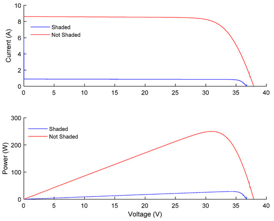
Figure 1.
I-V and P-V curve of a PV module when cells are shaded without bypass diodes.
Because of the nature of electrical characteristics of solar cells, the power losses are not proportional to the shaded areas, but greater [16]. Therefore, just a few parts of shading can drastically decrease the performance of the entire PV system. Considering small PV plants, where there are a few or no parallel connections, a small portion of shading can result in substantial power losses or the entire system failure [17].
In addition to power losses, reverse-biased behavior may lead to overheating the solar cell. Thus, and if the PV module does not have protection, the hotspot failure can arise and, in extreme cases, the panel can get permanently damaged.
A hotspot failure is a condition characterized when a part of the cell or PV module indicates a higher temperature than its surroundings. Typically, a hotspot arises as a consequence of power dissipation in a reverse-biased PV cell [18].
Permanent damage can occur when a PV cell reaches breakdown voltage, defined as the maximum allowed reverse voltage for the safe operation of the p-n junction. Reaching this voltage leads to a massive increase of the reverse current and eventually to device destruction [19]. Figure 2 illustrates the I-V curve of a photovoltaic cell when operating as fully illuminated and under shading conditions until reaching a breakdown voltage.
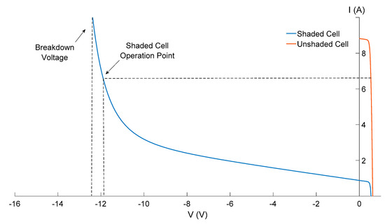
Figure 2.
I-V curve of a PV module in a reverse bias region.
The hotspot problem was identified early, also on the first PV module application [20,21]. Numerous studies have investigated the hotspot phenomenon and mitigations’ techniques to avoid power losses and prevent its adverse consequences [22,23,24,25,26]. Based on these experiences, a hotspot endurance test became part of the approval for types of crystalline silicon modules, according to IEC (International Electrotechnical Commission) 61215, which verifies the hotspot tolerance by recreating the worst expected operating conditions [27].
Despite all efforts to avoid the hotspot failure, it frequently occurs, leading to a decrease in the PV modules’ lifetime [28]. To prevent the hotspot failure, usually a passive bypass diode on PV modules is mounted. Further details on the essential theoretical background about bypass diodes as a mitigation technique will be briefly given in Section 3.
3. Bypass Diode: Working Principle
Aiming to prevent the shading consequences, manufacturers included one or more diodes on commercial PV panels. Bypass (BP) diodes are connected in antiparallel between a solar cell strings’ positive and negative output terminal, and generally is used for a small group of series cells [29].
Most modules intended for grid connection consists of 72–60 cells, arranged in three submodules of 24–20 cells, allowing placement of BP diodes to each of the submodules. Therefore, in conventional modules, part of its cells gets bypassed when a BP diode is activated. Such devices are accommodated in the junction box on the module’s rear side [30].
If one cell becomes reversed biased, it will directly bias the BP diode. Bypass diodes perform the function of providing a bypass path for the current flow. As the shading is removed, the cell typically returns to the for bias state, and the diode returns to the reversed bias state. Thus, the power generated by illuminated cells will not affected by the shading of other cells. Figure 3 exemplifies a PV module with 60 cells and subdivided with 20 cells per BP diode, working with one shaded cell.
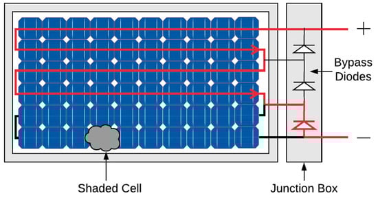
Figure 3.
PV module with one shaded cell.
Once bypass diodes conduct, they introduce inevitable voltage drop, may heat up significantly, and consume power generated. Hence, it brings impact to the maximum power delivered by the photovoltaic modules [31]. The configuration of bypass diodes on the PV modules forming part of the array has an important influence on the possibility of hotspot presence [8].
Even with the diode bypassing a complete substring and only one failing cell, the maximum power point (MPP) can be higher with activated bypasses. The difficulty with this approach is that the BP diodes create multiple local MPPs, which makes it hard for the maximum power point tracking (MPPT) to find the global MPP [7]. Therefore, distortion of the shaded I-V curve may lead to an error in the determination of the global MPP. Figure 4 illustrates the I-V and P-V curves of a shaded PV module with one BP diode activated (see Figure 3).
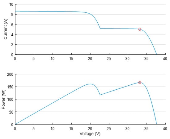
Figure 4.
I-V and P-V curves of a shaded PV module with one bypass diode activated.
Comparing Figure 1 and Figure 3, it is clear that under shading conditions the MPP is higher using BP diodes. Nevertheless, when BP diodes are activated, the PV module presents multiple local maxima (LM), but only one of them relates to the global maximum (GM) [32].
Overlapped and no-overlapped are two standard topologies of bypass diodes, as illustrated in Figure 5. It is worthy of mentioning that analyzing the PV modules with overlapped configuration is more complicated than no-overlapped because there will be a few different paths for the current flow [33].
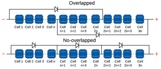
Figure 5.
Standard BP diode configurations.
Moreover, both configurations should be analyzed under a shading condition, as illustrated in Figure 6. The overlapped configuration may lead to an overcurrent situation. Increasing the output current of a PV module is not always attractive to the power plant, once all the project is developed to a current standard rate, and this situation may lead to negative consequences to the PV plant. Thus, the most used BP diode configuration by the PV module industry is the no-overlapped.
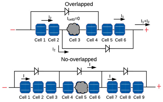
Figure 6.
BP diodes’ configuration under shading condition.
Various BP diode topologies inside a PV module can create a different path to the current flow. Thus, the BP diode arrangements on the PV panel may impact the voltage, current, and power characteristics of shaded and unshaded cells, as well as the maximum power extraction of the entire PV system. Hence, several studies have been done on the whole of the impact of BP diode configurations on the maximum power of the PV module.
How to Choose a Bypass Diode
Considering the bypass diode working principle discussed in Section 3, the BP diode needs to be activated even when a single cell is shaded. Ideally, the device should have forward voltage as low as possible. Hence, the most widely used diode is the Schottky diode because of its low forward voltage. Since the first industrial application of the BP diodes, the kind of diode mounted on the junction box was the Schottky diode [34].
However, a lower forward voltage means a higher leakage current, raising the risk of thermal runaway [35]. Thermal runaway occurs when BP diodes are operating on a quick switching mode, like when the shading on the PV module is suddenly removed. The power dissipation in the reverse bias is greater than the cooling capacity of the junction box. Therefore, the diode is subject to permanent damage, as is consequently, the PV module [36].
To avoid the risks of permanent damage and power losses associated with the BP diode, the correct device sizing is essential. The first criterion should be the PV module short-circuit current (Isc); once it is the current rate the diode will conduct. Then, the maximum repetitive reverse voltage (VRRM) needs to be considered.
The VRRM is related to the number of cells protected by the diode. For safe and efficient operation, the BP diode must conduct when one cell is shadowed, and the shadowed cell voltage must stay under its breakdown voltage. Thus, the maximum number of cells bridged by the one device (nmax) is limited by the cell’s breakdown voltage (Vcell), and the forward diode voltage (Vdiode) is calculated by Equation (1) [37].
Knowing the nmax and the panel open-circuit voltage (Voc), the maximum repetitive reverse voltage (VRRM) can be calculated by Equation (2).
Frequently, the junction box manufacturer is different from that of the PV module. The junction box is not designed to one specific panel but could be used by a range of solar PV modules. Thus, most of the used BP diodes show a VRRM = 45 V [37].
Considering the working principle and all the BP diode characteristics discussed, Section 4 will present a comprehensive literature review of BP diode studies, summarizing the collected experience and the state of the art within this subject.
4. Bypass Diode: State of the Art
A significant amount of published research studies have been reported in the literature about the possibility of hotspot appearance since early applications of PV systems and the importance of configuration of bypass diodes on the PV modules to minimize this problem.
In early steps of such studies, Baron and Virobik [38], in 1963, based on the shading problem, first successfully incorporated a shunt diode in the Pioneer Spacecraft solar arrays. Since then, some authors contributed to optimizing the PV module design using BP diodes as a mitigation technique for power losses and the hotspot problem.
In 1969, Blake and Hanson [20] investigated the hotspot failure mode on space solar arrays and suggested the use of BP diodes to avoid the hotspot phenomenon. Their conclusions were reinforced by other authors, affirming that adding diodes increases the fault tolerance and reliability of solar arrays [39,40]. The use of BP diodes was so far considered the best circuit design tool to reduce power loss and hotspot problems [41].
Meanwhile, in the 1980s, a few circuit-design strategies were investigated in order to study BP diodes’ application and reliability [42,43]. Ross [44] affirmed that it was mostly not viable to mount a bypass diode around every cell inside the module. Therefore, a single diode should protect a series of cells or entire panels.
An alternative approach to BP diodes was studied by Green [45], suggesting a new technique of a BP diode integrated into the cell in its manufacturing process. In this case, each cell would have its own integrated BP diode, and Green observed a reduction of power losses.
Other protection methods against hotspot phenomena were investigated. Larue and Trieu [21] tried to mitigate the heating problem by increasing the number of cells in parallel but concluded that BP diodes were better than the proposed method. Feldman et al. [13] also investigated an alternative protection method using a “pseudo-random” interconnection scheme. They concluded that for regular shadows in a terrestrial application, the pseudo-random interconnection scheme gave substantially higher output than the more conventional shunt-diode methodology.
Still in the 1980s, two other studies tested alternative techniques to the shading problem. In 1982, Cox et al. [46] explored mounting a peripheral bypass diode, aiming to reduce the PV cell reverse breakdown. Swaleh and Green [47] incorporated a relatively low shunt resistance in the solar cell. They concluded that bypass diodes across individual cells provide a more effective tolerance to the effects of shadows.
Forman and Ross [48,49] performed experimental tests on terrestrial PV modules. They observed numerous cell failures on a test PV system, and some of the PV modules did not use BP diodes, leading them to conclude that the severity of this condition would have been limited by using protective diodes.
Furthermore, in 1984, Shepard and Sigmura [50] discussed some BP diode configuration on a PV module, suggesting the integration of such device to the array mounting and external to the array configuration. They observed that the more BP diodes connected, the smaller the power losses. Gonzalez et al. [51] compared a PV module with and without the BP diode and concluded the use of BP diodes as a strategy for controlling the hotspot problem.
At the same time, General Electric (GE) developed a research under Jet Propulsion Laboratories’ (JPL) contract to study the design and processing techniques necessary to incorporate bypass diode to a PV module. The study analyzed some mounting topologies for BP diodes and compared their performance on mechanical, electrical, and thermal behaviors [34].
The report concluded that the use of BP diodes is essential to terrestrial PV arrays’ applications. The number of BP diodes should be proportional to the PV array area, not exceeding 15 series-connected solar cells within a bypassed group. The reliability of PV systems could reach a 20-year lifetime if correctly designed and installed with BP diodes [52].
This study indicated the use of the junction box to accommodate the BP diodes on the PV module, as manufacturers practice to date. The study also indicated that the cost to integrate such diodes could raise PV module costs [53].
Since GE’s research, bypass diodes incorporated into PV modules have been manufactured and placed in antiparallel to groups of series-connected solar cells and accommodated on the back of the panel on a designed site to mount these devices, the junction box. Although it established a standard technique to protect against the destructive effects of the hotspot, if shading any of these cells, BP diode would prevent the remainder of the group from contributing to the module output power. Likewise, the number of diodes, as well as their reliability, continued to be investigated in subsequent years [54,55].
In 1988, Bishop [56] conducted initial experiments about the performance of PV cells under an uneven irradiance and using BP diodes. His work described a software developed to simulate the effects on PV module due to mismatching conditions, such as manufacturers’ mismatching or shadowing conditions. Using the software developed, Bishop concluded that the drop in PV cell performance due to inadequate conditions was inevitable, so the use of BP diode is essential. Further, Abete et al. [57] employed Bishop’s method on a mismatched PV array with a BP diode to evaluate its performance. The conclusions helped to understand when the BP diode goes into operation.
In the same year, Lashway [58] raised a discussion about specific testing techniques for PV modules. One of these procedures was about measuring BP diodes’ current to identify a failure module. Besides, the author pointed out the same failure types that could occur on PV modules, and the BP diodes were responsible for 2% of the most common failures on a PV array.
During the period 1990–2005, there was no extensive research that emphasized the development of new concepts or, at least, a new investigation on the impact of hotspots on the PV modules’ reliability. Molenbroek et al. [22] tested PV modules’ hotspot susceptibility and concluded that the worst condition of hotspot heating was completely shading a single cell. However, the hotspot condition can be minimized using the BP diodes to limit the reverse bias voltage across a module to less than 1 V. Soon after, Nabeel et al. [59,60] tested PV modules’ reliability by theoretical and experimental results. The experiment about BP diode led them to conclude that the reliability of the module increased as the number of shunted diodes increased.
Afterward, Herrmann et al. [25] investigated the module design regarding bypass diodes. According to their conclusions, to avoid the overheating caused by partial shading, one single bypass diode should protect 20 cells maximum. Quaschning and Hanitscht [61] developed a simulation method to reproduce the solar cell I-V curve. Through this method, it was possible to study the electric performance of a PV system under a shading condition using BP diodes. They observed that the use of a BP diode reduced the power that would be lost with shading.
Still in the 1990s, studies comparing the application of integral diodes and conventional BP diodes to PV modules were performed. Analyzing how many cells of a PV module protected by one single BP diode could be affected by shading, Bhattacharya and Neogy [23] compared the usage of integral diodes or single diode for a group of cells. They pointed out that diodes integral with the solar cell would be the best solution in respect to power production.
Furthermore, Roche et al. [62] compared three methods to reduce mismatch losses: The use of integral BP diodes, series/parallel connections on the PV module, and reduced shunt resistance. The authors settled that integral BP diodes are a viable technique to prevent hotspot and power losses on PV systems. Furthermore, Yoshioka et al. [24] tested two PV modules, one using integral BP diodes, and the other with conventional external bypass diode. Their results indicated that modules with bypass diode function shown more power output and lower temperature increase when operating under shading conditions. Also, the conclusions suggested the use of PV modules with BP diodes to home installations.
Lastly, Danner and Bucher [26] analyzed reverse I-V characteristics of commercial cells that were measured and the impact on power dissipation. According to the study, the number of BP diodes in a PV panel should not be defined by the number of cells, but by the power capacity of the string cells if they become bypassed. This work once more emphasized the importance of incorporating bypass diodes into modules. Figure 7 summarizes in a chronological sequence the primary references aforementioned through the 1990s.
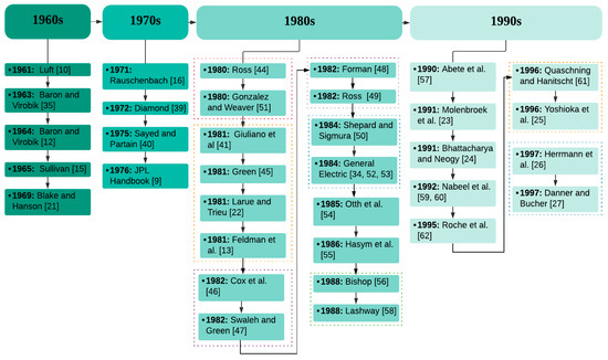
Figure 7.
Main references through the 1990s.
Other studies [63,64,65,66,67] show different ways to understand the impact of shading and hotspotting as well as non-uniformity of solar irradiance on PV output power generation, while using infrared imaging technique, which was firstly used in the field of PV installations.
The interest in understanding the impact of hotspots and shading increased as the production of PV modules increased across the globe. In 2005, Meyer and Van Dyk [67] investigated the relationship between the increase/decrease in the shunt resistance of PV cells and the existence of hotspots. It confirmed along with other research, such as [68,69,70], that shunt resistance causes hotspots in PV modules and the mitigation of this problem would not be merely possible by having a separate resistance load integrated with the bypass diode junction box. The researchers affirmed it was necessary for the use of thermography, too.
Early 2010, Simon and Meyer [71] developed a suitable method to detect and analyze the hotspots using a unique approach. The proposed technique consisted of using infrared (IR) thermography to assess the heat distribution on the PV modules’ surface. Moreover, using scanning electron microscopy, it was observed that the structural materials of the hotspotted solar cells were affected by irreversible destruction.
Additionally, Kernahan [72] proposed a new detection and prevention method for hotspots’ mitigation in solar cells. In simple, he proposed to connect subcells that are affected by a hotspot to an external BP diode or connect the whole substring to an external bypass diode interconnection, which would inherit the reversed current passing thought the hotspotted string, increasing the output current and, consequently, increasing the PV module power generation.
Until the early 2000s there was a relatively slow evolution on published research about the BP diodes. Since then, solar PV power has emerged as a possible alternative energy source, so the reliability of such systems has been extensively explored. Therefore, the shading problem and the hotspot, as wells as the BP diodes and other mitigation techniques, are widely studied and will be discussed in Section 4.1.
4.1. Recent State of the Art on Hotspot Mitigation Techniques
So far, BP diodes are consolidated as a protective device against power losses and the hotspot problem, although some failures and losses still are observed on PV modules. Thus, research about BP diodes continues to be developed. Recent works will be categorized into five types of research groups: Partial Shading, Bypass Diode Topology, Field Tests, Artificial Intelligence, and New Mitigation Techniques. Such studies are summarized in Table 1.

Table 1.
Classification of reference by specific subjects.
The Partial Shading category revisits the effect of the shading on the PV module, as well as the entire PV system, evaluating the power losses and the possibility for the hotspot rising. Partial shading is a critical discussion, especially when the urban PV systems became popular. These papers raised the demand for those studies developed in the Bypass Diode Topology category. In these studies, the number of BP diodes mounted on a PV module, along with the arrangement inside the panel, was extensively discussed.
Regarding the Field Tests’ category, on this research the performance of commercial PV modules was analyzed under real conditions, and by an extended period. In this kind of research, it was possible to identify the requirements of the PV plants, especially those related to the PV module reliability.
The Artificial Intelligence (AI) category on Table 1 refers to research that applies an AI technique for modelling [97,98,101] PV systems and predicting their performance [102,103,104], especially the ones related to analyzing shading effect [105], the hotspot problem, and the bypass diodes [106]. Using AI techniques on this concern enables reducing experimental costs once the results can be close to reality. On the other hand, there will be some unpredictable situations that were not considered in model training.
One new trend related to the BP diodes is the fault diagnosis on these devices using AI, developed by [99,100,107,108]. This is an excellent tool for identifying defects on the BP diodes, as well as detecting the hotspot problem. It is essential to early identify this kind of fault in order to avoid power losses, possibly permanent damage to the PV modules, and, consequently, the PV system reliability.
Even though bypass diodes are used for protection and qualification and tests are used to reduce cell mismatch, a few studies have reported these strategies to be insufficient for hotspot prevention. Some authors have recently asserted the need for new mitigation techniques.
Bauwens and Doutreloigne [7] developed a smart bypass switching device, using a NDMOS (Doubled-Diffused MOSFET). Simulations using the smart bypass, a typical BP diode, and an ideal diode were made. The authors concluded that smart bypass was more efficient once it did not produce heat or power losses, such as conventional BP diodes.
Kim and Krein [18] re-examined BP diodes, showing their inadequacy for hotspot protection. The authors concluded hotspotting could lead to a second breakdown or cell encapsulant damage and permanently degrade the PV panel or create safety concerns. The paper detailed the hotspot conditions and how they could occur. Moreover, the research explored some hotspot preventing methods, namely: BP diodes, active bypass switches, low reverse-breakdown voltage PV cells, and active hotspot detection and protection. These findings demonstrated that BP diodes are more effective at mitigating hotspots for short PV string lengths, but this is not conventionally implemented in modern panel construction.
One of the hotspots-preventing methods studied by [18] was the low reverse-breakdown voltage PV cells. In this regard, the SunPower® company manufactures a more shading-tolerant PV cell. This kind of cell has a low breakdown voltage, which occurs uniformly across the cell. In a shading situation or any other reverse-bias condition, thermal runaway is mitigated, lowering the PV cell temperature and, consequently, avoiding the hotspot, regardless of whether or not BP diodes are presented. However, when enough cells are in reverse bias, the cumulative power loss from the shaded cells can exceed the power produced from the cells in forwarding bias, so SunPower includes diode protection to enhance energy yield [113].
The lower heating on this kind of cell happens because the cell architecture places a heavily doped positive region immediately adjacent to a heavily doped negative region evenly across the back of the cell, resulting in a lower voltage potential for a cell in reverse bias. Additionally, SunPower® cells are connected with a strain-relieved copper bar and six solder pads per cell. Solder joints are small, so the mismatch from thermal expansion results in less stress in the joint [113].
Pannebakker et al. [109] proposed simulation and experiments using smart bypass diodes. They simulated and tested various patterns of shading, using 60, 20, 12, 6, and 3 BP diodes, in order to evaluate the decreasing power losses and heating by the BP diodes. The study concluded the more BP diodes were used, the higher the maximum power under shading condition, creating a more shade-resilient module. Although the proposed topology showed excellent results, the cost of integrating this new technique was considered high.
Even though previous studies showed high costs and unfeasibility to place one diode to each cell within the PV panel, there are some manufacturers producing modules with this kind of BP diode topology. For instance, AE Solar® produces a specific kind of PV module, named “smart hotspot-free”, which places one bypass diode for each cell in the module. The BP diodes are not placed on the junction box, as traditionally installed, but on the cell interconnection, as illustrate in Figure 8.
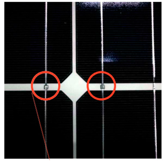
Figure 8.
BP diodes place on each cell [114].
The manufacturers’ test showed that the cell temperature under a shading situation could fall from 160 °C on conventional modules to 85 °C on this kind of BP diode topology. Moreover, it may increase the module lifetime and PV installation reliability [114].
In 2017, Dhimish et al. [115,110] proposed two hotspots’ mitigation techniques, where both consist of the integration of two MOSFETs (Metal-Oxide-Semiconductor Field Effect Transistor) connected to the affected PV module, as seen in Figure 9a. This arrangement was tested under several environmental conditions, where it was observed that both techniques would increase the output power of the PV module by 1.44 W and 3.97 W, respectively.
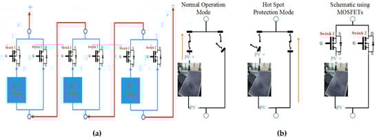
Figure 9.
Hotspot mitigation techniques proposed by [115]. (a) First mitigation technique, where the MOSFETs are connected across the PV strings of the PV module. (b) Second mitigation technique, where the MOSFETs are integrated across the whole terminals of the PV module.
By contrast with Dhimish et al. [115] observations, two other researchers, [116,117], observed the impact of the hotspots on the output power of the PV modules. It was concluded that the loss in the output power could be as high as 15% when the hotspots are affecting various cells in the PV module.
Dhimish et al. [111] conducted another observation of the impact of the second mitigation technique (shown in Figure 9b on the temperatures of the hotspotted solar cells. It was noticed that the temperature of the hotspotted cells could decrease in the range of 2.7–5.7 °F, as shown in Figure 10.
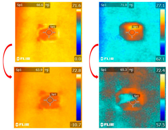
Figure 10.
Impact of hotspot mitigation technique on the hotspot temperature distribution [115].
In contrast with [111] results, it was observed by [118,119,120,121] that the hotspots’ temperature distribution was strongly dependent on various conditions including (1) the integration of the MPPT, (2) day-to-night temperature variations, (3) day-to-night irradiance variations, and, most importantly, (4) the amount of partial shading affecting the hotspotted PV modules.
The up-to-date research [122,123,124] discussed the fact that hotspots in PV modules are likely to occur when the PV modules are affected by cracks/microcracks. It was observed during the last three years that many old PV modules affected by hotspots, most frequently, are affected by microcracks.
In 2020, state-of-the-art research on the mitigation of PV hotspots using a new principle of integrating a current-limited circuit was proposed by [112]. The integration of this circuit is not only providing a suitable solution to mitigate the problem of hotspotting, but also eliminating the increase of the PV cells’ temperature during partial shading scenarios. Figure 11 shows the thermal image of a PV module, where two cells are under shading conditions.
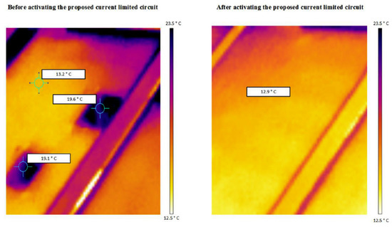
Figure 11.
Impact of hotspot mitigation technique developed by [112] on a PV module affected by two shaded solar cells.
It was presented that after using the proposed mitigation technique, the temperature of the shaded cells decreased equally to adjacent cells.
4.2. Emerging Modules’ Technologies and Bypass Diode Protection Device
Up to now, the paper discussed in detail about BP diodes and shading mitigation techniques on conventional PV modules. However, there are some emerging modules’ technologies, such as shingled modules and half-cells modules. These devices are also subjected to shading situations and need protection against the hotspot problem.
One of the ways to increase power density on a PV module is to improve the interconnection of the cells, making them closer, so the area producing power is more extensive. This logic is applied to shingled modules technology, where the cells are made from long strings of series-connected cell strips [125]. The shingled PV modules are specially designed to connect by a bus bar, using no space between each other, as illustrated in Figure 12.
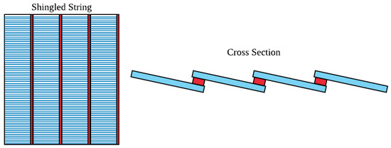
Figure 12.
Shingle PV module interconnection.
Despite the higher power capacity, this kind of module, when under a shading condition, will face the same consequences as the conventional ones. Thus, like other PV modules’ technologies, bypass diodes are placed in antiparallel and mounted on the junction box located on the rear side of the module. The number of BP diodes must follow the same principles applied to conventional PV modules [125].
Another rising technology is the half-cell PV modules. On this kind of PV module, the PV cells are cut in half, changing the configuration of the module. The current generated by a solar cell is proportional to the area exposed to solar irradiance. Thus, half-cells will produce half current. However, losses due to the series’ resistance of the cell connector in a PV module are proportional to the square of the current they conduct. So, half-cells reduce these losses substantially [126].
Half-cell modules have twice the number of cells than conventional modules. So, they require a rearranging of the PV module layout, especially on the bypass diodes’ connections. BP diodes are used as hotspot protection devices and are mounted on the junction box, as in conventional modules. Nevertheless, the number of cells protected by one single diode is going to change, as illustrated in Figure 13.
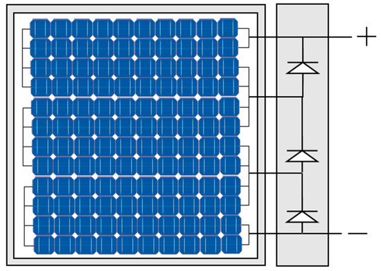
Figure 13.
Half-cell module BP diode connections.
Given the valuable experiences and ongoing feedback from the presented literature, the last part of this review paper, Section 5, provides the overall conclusions and discusses the future issues about the BP diodes and hotspot mitigation techniques.
5. Conclusions
This review paper was structured to give an overview of the bypass diode application on PV modules. First, the partial shading effect was discussed, aiming to understand how it can lead to the hotspot problem, as well as how it can result in power losses and I-V and P-V curves’ distortions. Moreover, hotspots may cause permanent cell damage, and are still one of the most frequently reported phenomena to limit module lifetime.
The primary prevention method for hotspotting is a bypass diode, wired in antiparallel to solar cells’ submodule, and mounted on the junction box on the back of PV modules. Bypass diodes perform the function of providing a bypass path for the current flow in case some cells are partially shaded, avoiding the hotspot problem and increasing the MPP. However, once bypass diodes are activated, the MPPT becomes disoriented because of the multiple peaks on the P-V curve. Moreover, when bypass diodes conduct, they consume part of generated power, impacting the maximum power delivered by PV modules.
Lastly, the study brings an extensive overview of all research progress on bypass diodes since its first uses, allowing us to understand how the technology developed and advanced over recent years. Recent research was organized into five categories, as shown in Table 1.
Partial shading concerns studies on the impact of shading on PV systems. It is an essential field of study because it helps to clearly understand the power losses and the possible permanent damage to the PV modules associated with shading situations. It is becoming increasingly important with the recent growth of PV systems’ installations in urban areas. On the other hand, extensive studies have shown that there always will be some unpredictable situations involving the shading of PV modules.
Regarding the Bypass Diode Topology category, it was subject to extensive research over the past decades. These studies stated that the PV systems’ reliability is related to the number of BP diodes mounted on the PV modules. The more diodes installed, the fewer power losses associated with shading, as well as the decrease of the hotspot rising. However, increasing the number of diodes is costly and makes the PV module arrangement complex. Thus, changing the BP diode topology has not shown a significant increase in the PV systems’ yields. Up to now, the Schottky diode was the most applied kind of device on the PV modules’ industry. Therefore, it is possible to conclude that this research led us to investigate new mitigation techniques to the shading and hotspot problem.
New strategies for the shading and hotspot phenomenon, as well as the BP diodes, have been investigated in recent studies. For instance, the studies developed by [109,111] used a smart BP diode and a MOSFET, respectively, substituting the conventional BP diode. Both studies have proven to be efficient in reducing the hotspot and power losses. Though, just like any new technology, most of these studies have shown to be costly
Field Tests is an indispensable category because it analyzes the PV systems exposed to real conditions, so its results can bring support to other researchers and adapt other studies to what issues need to be addressed on the PV systems. However, it can be costly compared to simulation studies and can take a longer time. The field test analyzed in the article reinforced that the BP diodes are essential to the PV modules’ reliability, although they are devices susceptible to fails, which may lead to consequences of power losses and the hotspot phenomenon.
Some recent researchers are applying artificial intelligence techniques on the PV systems field. It can be used on modelling and predicting PV systems’ performance. Specifically about shading, hotspots, and BP diodes, these studies improved detecting device faults, supports visual inspections, and detecting shading on PV systems. It can be a helpful tool, because it enables detecting earlier failures that can cause losses or damage to the systems. Nevertheless, there will be some situations not predicted on the AI training.
All these categories analyzed in this review article aim to mitigate the shading effect and the hotspot problem. The primary strategy is using the BP diodes, as discussed before, but all studies cited are correlated with the purpose of minimizing power losses, possibly permanent damage, and the overall PV module reliability regarding the shading situation.
Even though bypass diodes are a consolidated mitigation technique to the shading problem, a few studies have reported these strategies to be insufficient for hotspot prevention, especially concerning power consumption, diodes faults, and introducing multiple peaks on P-V curves.
Author Contributions
R.G.V. conceived the methodology, developed theory, and performed simulations. F.M.U.d.A. conceived the idea, performed the supervision, and contributed to the revision of the manuscript. M.D. developed theory, provided critical feedback, and helped shaping the research. M.I.S.G. provided critical feedback and contributed to the revision of the manuscript. All authors have read and agreed to the published version of the manuscript.
Funding
This research received no external funding.
Acknowledgments
The authors would like to acknowledge the support provided by the Semi-Arid Federal University, the University of Rio Grande do Norte and the University of Huddersfield in the framework of an international contribution.
Conflicts of Interest
The authors declare no conflict of interest.
References
- Kalogirou, S. Solar Energy Engineering: Processes and Systems, 1st ed.; Elsevier Inc.: London, UK, 2009; ISBN 9780123745019. [Google Scholar]
- IEA. A Snapshot of Global Photovoltaic Markets; IEA: Brussels, Belgium, 2018. [Google Scholar]
- Tiwari, G.N.; Dubey, S. Fundamentals of Photovoltaic Modules and Their Applications, 1st ed.; The Royal Society of Chemistry: Cambridge, UK, 2010; ISBN 978-1-84973-020-4. [Google Scholar]
- Tsanakas, J.A.; Ha, L.; Buerhop, C. Faults and infrared thermographic diagnosis in operating c-Si photovoltaic modules: A review of research and future challenges. Renew. Sustain. Energy Rev. 2016, 62, 695–709. [Google Scholar] [CrossRef]
- La Manna, D.; Li Vigni, V.; Riva Sanseverino, E.; Di Dio, V.; Romano, P. Reconfigurable electrical interconnection strategies for photovoltaic arrays: A review. Renew. Sustain. Energy Rev. 2014, 33, 412–426. [Google Scholar] [CrossRef]
- Ramaprabha, R.; Mathur, B.L. A Comprehensive Review and Analysis of Solar Photovoltaic Array Configurations under Partial Shaded Conditions. Int. J. Photoenergy 2012, 2012, 1–16. [Google Scholar] [CrossRef]
- Bauwens, P.; Doutreloigne, J. Reducing partial shading power loss with an integrated Smart Bypass. Sol. Energy 2014, 103, 134–142. [Google Scholar] [CrossRef]
- Silvestre, S.; Boronat, A.; Chouder, A. Study of bypass diodes configuration on PV modules. Appl. Energy 2009, 86, 1632–1640. [Google Scholar] [CrossRef]
- JPL. Solar Cell Array Design Handbook, 1st ed.; NASA: Pasadena, CA, USA, 1976; Volume I. [Google Scholar]
- Luft, W. Partial shading of silicon solar cell converter panels. In Proceedings of the AIEE Conference, Los Angeles, CA, USA, 9–11 May 1961; pp. 62–204. [Google Scholar]
- Conn, A.A. Computer Computation of Shadow Effects on Solar Cell Arrays; Eng. Rep. 9361.11-E72; TRW Systems, Inc.: Redondo Beach, CA, USA, 21 December 1966. [Google Scholar]
- Baron, W.R.; Virobik, P.F. Solar Array Shading and a Method of Reducing the Associated Power Losses. In Proceedings of the IEEE 4th Photovoltaic Specialists Conference, Cleveland, OH, USA, 2–3 June 1964. [Google Scholar]
- Feldman, J.; Singer, S.; Braunstein, A. Solar Cell Interconnections and the. Sol. Energy 1981, 26, 419–428. [Google Scholar] [CrossRef]
- Jett, P.L.; Miller, J.L. Analysis of effects of shadowed and open solar cells on orbital workshop solar cell array performance. In Proceedings of the 6th IECE Conference, Boston, MA. USA, 3–5 August 1971. [Google Scholar]
- Sullivan, R.M. Shadows Effect on Serie-Parellel Array of Solar Cells; Rep. N6529814; NASA Goddard Space Flight Center: Greenbelt, MD, USA, 1965. [Google Scholar]
- Rauschenbach, H.S. Electrical Output of Shadowed Solar Arrays. IEEE Trans. Electron Devices 1971, 18, 483–490. [Google Scholar] [CrossRef]
- Kaushika, N.D.; Rai, A.K. An investigation of mismatch losses in solar photovoltaic cell networks. Energy 2007, 32, 755–759. [Google Scholar] [CrossRef]
- Kim, K.A.; Krein, P.T. Reexamination of Photovoltaic Hot Spotting to Show Inadequacy of the Bypass Diode. IEEE J. Photovoltaics 2015, 5, 1435–1441. [Google Scholar] [CrossRef]
- Daliento, S.; Di Napoli, F.; Guerriero, P.; d’Alessandro, V. A modified bypass circuit for improved hot spot reliability of solar panels subject to partial shading. Sol. Energy 2016, 134, 211–218. [Google Scholar] [CrossRef]
- Blake, F.A.; Hanson, K.L. The Hot-spot failure mode for Solar Arrays. In Proceedings of the 4th IECEC Conference, Washington, DC, USA, 22–26 Semptember 1969. [Google Scholar]
- Larue, J.C.; Du Trieu, E. Effect of Partial Shadowing on Solar Panels Hot Spot or Breakdown? In Proceedings of the Photovoltaic Solar Energy Conference, Cannes, France, 27–31 October 1980; pp. 490–495. [Google Scholar]
- Molenbroek, E.; Waddington, D.W.; Emery, K.A. Hot spot susceptibility and testing of PV modules. In Proceedings of the the Conference Record of the Twenty-Second IEEE Photovoltaic Specialists Conference, Las Vegas, NV, USA, 7–11 October 1991; pp. 547–552. [Google Scholar]
- Bhattacharya, G.; Neogy, C. Removal of the hot-spot problem in photovoltaic modules and arrays. Sol. Cells 1991, 31, 1–12. [Google Scholar] [CrossRef]
- Yoshioka, H.; Nishikawa, S.; Nakajima, S.; Asai, M.; Takeoka, S.; Matsutani, T.; Suzuki, A. Non hot-spot PV module using solar cells with bypass diode function. In Proceedings of the Conference Record of the Twenty Fifth IEEE Photovoltaic Specialists Conference, Washington, DC, USA, 13–17 May 1996; pp. 1271–1274. [Google Scholar]
- Herrmann, W.; Wiesner, W.; Vaassen, W. Hot spot investigations on PV modules-new concepts for a test standard and consequences for module design with respect to bypass diodes. In Proceedings of the Conference Record of the Twenty Sixth IEEE Photovoltaic Specialists Conference, Anaheim, CA, USA, 29 September–3 October 1997; pp. 1129–1132. [Google Scholar]
- Danner, M.; Bucher, K. Reverse characteristics of commercial silicon solar cells-impact on hot spot temperatures and module integrity. In Proceedings of the Conference Record of the Twenty Sixth IEEE Photovoltaic Specialists Conference, Anaheim, CA, USA, 29 September–3 October 1997; pp. 1137–1140. [Google Scholar]
- Woyte, A.; Nijs, J.; Belmans, R. Shadowing of Photovoltaic Arrays With Different System Configurations: Literature. Sol. Energy 2003, 74, 217–233. [Google Scholar] [CrossRef]
- IEA. Review on Failures of Photovoltaic Modules; IEA: Brussels, Belgium, 2013. [Google Scholar]
- Ko, S.W.; Ju, Y.C.; Hwang, H.M.; So, J.H.; Jung, Y.S.; Song, H.J.; Song, H.E.; Kim, S.H.; Kang, G.H. Electric and thermal characteristics of photovoltaic modules under partial shading and with a damaged bypass diode. Energy 2017, 128, 232–243. [Google Scholar] [CrossRef]
- Wirth, H.; Weiß, K.-A.; Wiesmeier, C. Photovoltaic Modules Technology and Reliability, 1st ed.; De Gruyter: Berlin, Germany, 2016; ISBN 978-3-11-034827-9. [Google Scholar]
- Teo, J.C.; Tan, R.H.G.; Mok, V.H.; Ramachandaramurthy, V.K. Effects of bypass diode configurations to the maximum power of photovoltaic module. Int. J. Smart Grid Clean Energy 2017, 6, 225–232. [Google Scholar] [CrossRef]
- Ahmad, R.; Murtaza, A.F.; Ahmed Sher, H.; Tabrez Shami, U.; Olalekan, S. An analytical approach to study partial shading effects on PV array supported by literature. Renew. Sustain. Energy Rev. 2017, 74, 721–732. [Google Scholar] [CrossRef]
- Ekpenyong, E.E.; Anyasi, F. Effect of Shading on Photovoltaic Cell. IOSR J. Electr. Electron. Eng. 2013, 8, 2278. [Google Scholar]
- General Electric. Final Report Bypass Didode Integration; General Electric: Pasadena, CA, USA, 1981; Volume 4. [Google Scholar]
- Petrone, G.; Ramos-Paja, C.A.; Spagnuolo, G. Photovoltaic Sources Modeling, 1st ed.; Wiley: Hoboken, NJ, USA, 2017; ISBN 9781118679036. [Google Scholar]
- Shiradkar, N.; Gade, V.; Sundaram, K. Predicting service life of bypass diodes in photovoltaic modules. In Proceedings of the 2015 IEEE 42nd Photovoltaic Specialist Conference (PVSC 2015), New Orleans, LA, USA, 14–19 June 2015. [Google Scholar]
- STMicroelectronics. How to Choose a Bypass Diode for a Silicon Panel Junction Box; DOC ID 019041 Rev 1; STMicroelectronics: Geneva, Switzerland, 2011. [Google Scholar]
- Baron, W.R.; Virobik, P.F. Effect of shadows on solar array output. In Proceedings of the IEEE 4th Photovoltaic Specialists Conference, Cleveland, OH, USA, 2–3 June 1964. [Google Scholar]
- Diamond, R.M. Advanced developments of integral diodes in solar cells. In Proceedings of the 9th IEEE Photovoltaic Specialist Conferente, Silver Springs, MD, USA, 2–4 May 1972. [Google Scholar]
- Sayed, M.; Partain, L. Effect of shading on CdS CuxS solar cells and optimal solar array design. Energy Convers. 1975, 14, 61–71. [Google Scholar] [CrossRef]
- Gonzalez, C.; Weaver, R. Circuit Design Considerations for Photovoltaic Modules and Systems. In Proceedings of the 14th IEEE Photovoltaic Specialists Conference, San Diego, CA, USA, 7–10 January 1980. [Google Scholar]
- Friedrich, G.; Rasch, K.D.; Roy, K. Diodes for space solar arrays. In Proceedings of the 3rd Photovoltaic Solar Energy Conference, Cannes, France, 27–31 October 1980. [Google Scholar]
- Giuliano, M.; Starley, D.; Warfield, D.; Schuyler, T. By-pass diode design, application and reliability studies for solar cell arrays. In Proceedings of the 15th Photovoltaic Specialists Conference, Kissimmee, FL, USA, 12–15 May 1981. [Google Scholar]
- Ross, R.G. Flat-Plate Photovoltaic Array Design Optimization. In Proceedings of the 14th IEEE Photovoltaic Specialists Conference, San Diego, CA, USA, 7–10 January 1980. [Google Scholar]
- Green, M.A.; Gauja, E.; Withayachamnankul, W. Silicon solar cells with integral bypass diodes. Sol. Cells 1981, 3, 233–244. [Google Scholar] [CrossRef]
- Cox, C.H.; Silversmith, D.J.; Mountain, R.W. Reduction of Photovoltaic Cell Reverse Breakdown by a Peripheral Bypass Diode. In Proceedings of the 16th IEEE Photovoltaics Specialists Conference, San Diego, CA, USA, 28 September 1982; pp. 834–839. [Google Scholar]
- Swaleh, M.S.; Green, M.A. Effect of shunt resistance and bypass diodes on the shadow tolerance of solar cell modules. Sol. Cells 1982, 5, 183–198. [Google Scholar] [CrossRef]
- Forman, S.E. Performance of Experimental Terrestrial Photovoltaic Modules. IEEE Trans. Reliab. 1982, 31, 235–245. [Google Scholar] [CrossRef]
- Ross, R.G. Releability and Performance Experience with Flat-Plate Photovoltaic Modulues. In Proceedings of the Fourth E. C. Photovoltaic Solar Energy Conference, Stresa, Italy, 10–14 May 1982; pp. 169–178. [Google Scholar]
- Shepard, N.F., Jr.; Sugimura, R.S. The Integration of Bypass Diodes with Terrestrial Photovoltaic Modules and Arrays. In Proceedings of the 17th IEEE Photovoltaic Specialists Conference, Kissimmee, FL, USA, 1–4 May 1984; pp. 676–681. [Google Scholar]
- Gonzalez, C.C.; Weaver, R.W.; Ross, R.G., Jr.; Spencer, R.; Arnett, J.C. Determination of Hot-Spot Susceptobility of Multistring Photovoltaic Modules in Central-Station Application. In Proceedings of the 17th IEEE Photovoltaic Specialists Conference, Kissimmee, FL, USA, 1–4 May 1984; Volume 13, pp. 668–675. [Google Scholar]
- General Electric. Diodes in Photovoltaic Modules and Arrays; General Electric: Pasadena, CA, USA, 1984. [Google Scholar]
- General Electric. Photovoltaic Module Bypass Diode Encapsulation; General Electric: Pasadena, CA, USA, 1983. [Google Scholar]
- Otth, D.H.; Sugimura, R.S.; Ross, R.G., Jr. Development of Design Criteria and Qualification Tests for Bypass Didodes in Photovoltaic Applications. In Proceedings of the Institute of Environmental Sciences-31st Annual Technical Meeting, Las Vegas, NV, USA, 29 April–3 May 1985. [Google Scholar]
- Hasyim, E.S.; Wenham, S.R.; Green, M.A. Shadow Tolerance of Modules Incorporating Integral Bypass Diode Solar Cells. Sol. Cells 1986, 19, 109–122. [Google Scholar] [CrossRef]
- Bishop, J.W. Computer simulation of the effects of electrical mismatches in photovoltaic cell interconnection circuits. Sol. Cells 1988, 25, 73–89. [Google Scholar] [CrossRef]
- Abete, A.; Barbisio, E.; Cane, F.; Demartini, P. Analysis of photovoltaic modules with protection diodes in presence of mismatching. In Proceedings of the IEEE Conference on Photovoltaic Specialists, Kissimmee, FL, USA, 21–25 May 1990; pp. 1005–1010. [Google Scholar]
- Lashway, C. Photovoltaic System Testing Techniques and Results. IEEE Trans. Energy Convers. 1988, 4, 503–506. [Google Scholar] [CrossRef]
- Al-Rawi, N.A.; Al-Kaisi, M.M.; Asfer, D. Reliability of photovoltaic modules I. Theoretical considerations. Sol. Energy Mater. Sol. Cells 1994, 31, 455–468. [Google Scholar] [CrossRef]
- Al-Rawi, N.A.; Al-Kaisi, M.M.; Asfer, D.J. Reliability of photovoltaic modules II. Interconnection and bypass diodes effects. Sol. Energy Mater. Sol. Cells 1994, 31, 469–480. [Google Scholar] [CrossRef]
- Quasching, V.; Hanitscht, R. Numerical Simulation of Current-Voltage Characteristics of Photovoltaic Systems with Shaded Solar Cells. Sol. Energy 1996, 56, 513–520. [Google Scholar] [CrossRef]
- Roche, D.; Outhred, H.; Kaye, R.J. Analysis and control of mismatch power loss in photovoltaic arrays. Prog. Photovolt. Res. Appl. 1995, 3, 115–127. [Google Scholar] [CrossRef]
- Kovach, A.; Schmid, J. Determination of energy output losses due to shading of building-integrated photovoltaic arrays using a raytracing technique. Sol. Energy 1996, 57, 117–124. [Google Scholar] [CrossRef]
- Kaminski, A.; Jouglar, J.; Mergui, M.; Jourlin, Y.; Bouille, A.; Vuillermoz, P.L.; Laugier, A. Infrared characterization of hot spots in solar cells with high precision due to signal treatment processing. Sol. Energy Mater. Sol. Cells 1998, 51, 233–242. [Google Scholar] [CrossRef]
- King, D.L.; Kratochvil, J.A.; Quintana, M.A.; McMahon, T.J. Applications for infrared imaging equipment in photovoltaic cell, module, and system testing. In Proceedings of the Conference Record of the Twenty-Eighth IEEE Photovoltaic Specialists Conference, Anchorage, AK, USA, 15–22 September 2000; pp. 1487–1490. [Google Scholar]
- Meyer, E.L.; Van Dyk, E.E. Assessing the reliability and degradation of photovoltaic module performance parameters. IEEE Trans. Reliab. 2004, 53, 83–92. [Google Scholar] [CrossRef]
- Meyer, E.L.; Van Dyk, E.E. The effect of reduced shunt resistance and shading on photovoltaic module performance. In Proceedings of the Conference Record of the Thirty-first IEEE Photovoltaic Specialists Conference, Lake Buena Vista, FL, USA, 3–7 January 2005; pp. 1331–1334. [Google Scholar]
- Muñoz, J.; Lorenzo, E.; Martínez-Moreno, F.; Marroyo, L.; García, M. An investigation into hot-spots in two large grid-connected PV plants. Prog. Photovolt. Res. Appl. 2008, 16, 693–701. [Google Scholar] [CrossRef]
- TamizhMani, G.; Sharma, S. Hot spot evaluation of photovoltaic modules. Reliab. Photovolt. Cells Modul. Components Syst. 2008, 7048, 70480K. [Google Scholar]
- Bauer, J.; Wagner, J.M.; Lotnyk, A.; Blumtritt, H.; Lim, B.; Schmidt, J.; Breitenstein, O. Hot spots in multicrystalline silicon solar cells: Avalanche breakdown due to etch pits. Phys. Status Solidi (RRL)–Rapid Res. Lett. 2009, 3, 40–42. [Google Scholar] [CrossRef]
- Simon, M.; Meyer, E.L. Detection and analysis of hot-spot formation in solar cells. Sol. Energy Mater. Sol. Cells 2010, 94, 106–113. [Google Scholar] [CrossRef]
- Kernahan, K. Detecting and Prevention of Hot Spots in Solar Panel 2011, 8,050,804; U.S. Patent and Tradema: Washington, DC, USA, 2011. [Google Scholar]
- Nageh, M.; Anis, W.R.; Hafez, I.M. A Proposed Solution for Partial Shadowing. Int. J. Comput. Appl. 2015, 121, 28–38. [Google Scholar] [CrossRef]
- Sathyanarayana, P.; Ballal, R.; Sagar, P.L.; Kumar, G. Effect of Shading on the Performance of Solar PV Panel. Energy Power 2015, 5, 1–4. [Google Scholar]
- Dash, R.; Swain, S.; Panda, P. Solar Photovoltaic Cell During Shading Condition. In Proceedings of the International Conference on Circuit, Power and Computing Technologies, Nagercoil, India, 18–19 March 2016. [Google Scholar]
- Torres, J.P.N.; Nashih, S.K.; Fernandes, C.A.F.; Leite, J.C. The effect of shading on photovoltaic solar panels. Energy Syst. 2018, 9, 195–208. [Google Scholar] [CrossRef]
- Mahammed, I.H.; Arab, A.H.; Berrah, S.; Bakelli, Y.; Khennene, M.; Oudjana, S.H.; Fezzani, A.; Zaghba, L. Outdoor study of partial shading effects on different PV modules technologies. Energy Procedia 2017, 141, 81–85. [Google Scholar] [CrossRef]
- Lee, H.-G.; Shah, J.N.; Tyagi, P.M.V. Analysis of Partial Shading Effects of Solar PV Module Configurations Using MATLAB/Simulink. Am. J. Energy Res. 2018, 6, 8–18. [Google Scholar] [CrossRef][Green Version]
- Alonso-García, M.C.; Ruiz, J.M.; Herrmann, W. Computer simulation of shading effects in photovoltaic arrays. Renew. Energy 2006, 31, 1986–1993. [Google Scholar] [CrossRef]
- Patel, H.; Agarwal, V. MATLAB-based modeling to study the effects of partial shading on PV array characteristics. IEEE Trans. Energy Convers. 2008, 23, 302–310. [Google Scholar] [CrossRef]
- Benghanem, M.S.; Alamri, S.N. Modeling of photovoltaic module and experimental determination of serial resistance. J. Taibah Univ. Sci. 2009, 2, 94–105. [Google Scholar] [CrossRef]
- Martínez-Moreno, F.; Muñoz, J.; Lorenzo, E. Experimental model to estimate shading losses on PV arrays. Sol. Energy Mater. Sol. Cells 2010, 94, 2298–2303. [Google Scholar] [CrossRef]
- Ishaque, K.; Salam, Z. Syafaruddin A comprehensive MATLAB Simulink PV system simulator with partial shading capability based on two-diode model. Sol. Energy 2011, 85, 2217–2227. [Google Scholar] [CrossRef]
- Guo, S.; Walsh, T.M.; Aberle, A.G.; Peters, M. Analysing partial shading of PV modules by circuit modelling. In Proceedings of the 2012 38th IEEE Photovoltaic Specialists Conference, Austin, TX, USA, 3–8 June 2012; pp. 2957–2960. [Google Scholar]
- Bai, J.; Cao, Y.; Hao, Y.; Zhang, Z.; Liu, S.; Cao, F. Characteristic output of PV systems under partial shading or mismatch conditions. Sol. Energy 2015, 112, 41–54. [Google Scholar] [CrossRef]
- Shin, W.G.; Ko, S.W.; Song, H.J.; Ju, Y.C.; Hwang, H.M.; Kang, G.H. Origin of bypass diode fault in c-Si photovoltaic modules: Leakage current under high surrounding temperature. Energies 2018, 11, 2416. [Google Scholar] [CrossRef]
- Mermoud, A.; Lejeune, T. Partial Shadings on Pv Arrays: By-Pass Diode Benefits Analysis. In Proceedings of the 25th European Photovoltaic Solar Energy Conference, Feria Valencia, Spain, 6–10 September 2010; pp. 6–10. [Google Scholar]
- Zheng, H.; Li, S.; Challoo, R.; Proano, J. Shading and bypass diode impacts to energy extraction of PV arrays under different converter configurations. Renew. Energy 2014, 68, 58–66. [Google Scholar] [CrossRef]
- Aliyu, S.; Lawan, S.; Araga, I.A.; Olatunde, A.F. Modeling impact of bypass diodes on photovoltaic cell performance under partial shading. Acad. J. Sci. Eng. 2016, 10, 24–30. [Google Scholar]
- Duong, M.Q.; Sava, G.N.; Ionescu, G.; Necula, H.; Leva, S.; Mussetta, M. Optimal bypass diode configuration for PV arrays under shading influence. In Proceedings of the 2017 IEEE International Conference on Environment and Electrical Engineering and 2017 IEEE Industrial and Commercial Power Systems Europe (EEEIC/I&CPS Europe), Milan, Italy, 6–9 June 2017. [Google Scholar]
- Fadliondi, F.; Isyanto, H.; Budiyanto, B. Bypass Diodes for Improving Solar Panel Performance. Int. J. Electr. Comput. Eng. 2018, 8, 2703–2708. [Google Scholar] [CrossRef]
- Greacen, C.; Green, D. The role of bypass diodes in the failure of solar battery charging stations in Thailand. Sol. Energy Mater. Sol. Cells 2001, 70, 141–149. [Google Scholar] [CrossRef]
- Alonso-García, M.C.; Herrmann, W.; Böhmer, W.; Proisy, B. Thermal and electrical effects caused by outdoor hot-spot testing in associations of photovoltaic cells. Prog. Photovolt. Res. Appl. 2003, 11, 293–307. [Google Scholar] [CrossRef]
- Kato, K. PVRessQ!: A research activity on reliability of PV systems from an user’s viewpoint in Japan. Reliab. Photovolt. Cells Modul. Components Syst. IV 2011, 8112, 81120K. [Google Scholar]
- Dhere, N.G.; Shiradkar, N.; Schneller, E.; Gade, V. The reliability of bypass diodes in PV modules. Reliab. Photovolt. Cells Modul. Components Syst. VI 2013, 8825, 88250I. [Google Scholar]
- Bana, S.; Saini, R.P. Experimental investigation on power output of different photovoltaic array configurations under uniform and partial shading scenarios. Energy 2017, 127, 438–453. [Google Scholar] [CrossRef]
- Elshatter, T.F.; Elhagry, M.T.; Abou-Elzahab, E.M.; Elkousy, A.A.T. Fuzzy Modeling of Photovoltaic Panel Equivalent Ccircuit. In Proceedings of the Conference Record of the Twenty-Eighth IEEE Photovoltaic Specialists Conference-2000 (Cat. No. 00CH37036), Anchorage, AK, USA, 15–22 September 2000; pp. 1656–1659. [Google Scholar]
- Karatepe, E.; Boztepe, M.; Çolak, M. Development of a suitable model for characterizing photovoltaic arrays with shaded solar cells. Sol. Energy 2007, 81, 977–992. [Google Scholar] [CrossRef]
- Zaki, S.A.; Zhu, H.; Yao, J. Fault detection and diagnosis of photovoltaic system using fuzzy logic control. In Proceedings of the 4th International Conference on Sustainable and Renewable Energy Engineering, Beijing, China, 11–13 May 2019; Volume 107, pp. 1–6. [Google Scholar]
- Kaid, I.; Hafaifa, A.; Guemana, M.; Hadroug, N.; Kouzou, A.; Mazouz, L. Photovoltaic system failure diagnosis based on adaptive neuro fuzzy inference approach: South Algeria solar power plant. J. Clean. Prod. 2018, 204, 169–182. [Google Scholar] [CrossRef]
- Askarzadeh, A.; Rezazadeh, A. Parameter identification for solar cell models using harmony search-based algorithms. Sol. Energy 2012, 86, 3241–3249. [Google Scholar] [CrossRef]
- Kalogirou, S.A. Applications of artificial neural-networks for energy systems. Appl. Energy 2000, 67, 17–35. [Google Scholar] [CrossRef]
- Balzani, M.; Reatti, A. Neural network based model of a PV array for the optimum performance of PV system. In Proceedings of the 2005 PhD Research in Microelectronics and Electronics, Lausanne, Switzerland, 28 July 2005; Volume II, pp. 323–326. [Google Scholar]
- Elsheikh, A.H.; Sharshir, S.W.; Abd Elaziz, M.; Kabeel, A.E.; Guilan, W.; Haiou, Z. Modeling of solar energy systems using artificial neural network: A comprehensive review. Sol. Energy 2019, 180, 622–639. [Google Scholar] [CrossRef]
- Giraud, F.; Salameh, Z.M. Analysis of the Effects of a Passing Cloud on a Grid-Interactive Photovoltaic System with Battery Storage using Neural Networks. IEEE Trans. Energy Convers. 1999, 14, 1572–1577. [Google Scholar] [CrossRef]
- Dhimish, M.; Holmes, V.; Mehrdadi, B.; Dales, M.; Mather, P. Detecting Defective Bypass Diodes in Photovoltaic Modules using Mamdani Fuzzy Logic System. Glob. J. Res. Eng. F Electr. Electron. Eng. 2017, 17, 33–44. [Google Scholar]
- Triki-Lahiani, A.; Bennani-Ben Abdelghani, A.; Slama-Belkhodja, I. Fault detection and monitoring systems for photovoltaic installations: A review. Renew. Sustain. Energy Rev. 2018, 82, 2680–2692. [Google Scholar] [CrossRef]
- Dhimish, M.; Holmes, V.; Mehrdadi, B.; Dales, M. Multi-layer photovoltaic fault detection algorithm. High Volt. 2017, 2, 244–252. [Google Scholar] [CrossRef]
- Pannebakker, B.B.; de Waal, A.C.; van Sark, W.G.J.H.M. Photovoltaics in the shade: One bypass diode per solar cell revisited. Prog. Photovolt. Res. Appl. 2017, 25, 836–849. [Google Scholar] [CrossRef]
- Dhimish, M.; Holmes, V.; Mather, P.; Sibley, M. Novel hot spot mitigation technique to enhance photovoltaic solar panels output power performance. Sol. Energy Mater. Sol. Cells 2018, 179, 72–79. [Google Scholar] [CrossRef]
- Dhimish, M.; Holmes, V.; Mehrdadi, B.; Dales, M.; Mather, P. PV output power enhancement using two mitigation techniques for hot spots and partially shaded solar cells. Electr. Power Syst. Res. 2018, 158, 15–25. [Google Scholar] [CrossRef]
- Dhimish, M.; Badran, G. Current limiter circuit to avoid photovoltaic mismatch conditions including hot-spots and shading. Renew. Energy 2020, 145, 2201–2216. [Google Scholar] [CrossRef]
- Power, S. SunPower® Module 40-year Useful Life; SunPower Corporation: San Jose, CA, USA, 2013. [Google Scholar]
- Solar, A. AE Smart Hot-Spot Free; WEE DE 20958316; AE Solar Alternative Energie: Konigsbrunn, Germany, 2019. [Google Scholar]
- Dhimish, M.; Holmes, V.; Mehrdadi, B.; Dales, M.; Mather, P. Output-power enhancement for hot spotted polycrystalline photovoltaic solar cells. IEEE Trans. Device Mater. Reliab. 2017, 18, 37–45. [Google Scholar] [CrossRef]
- Chaudhary, A.S.; Chaturvedi, D.K. Observing Hotspots and Power Loss in Solar Photovoltaic Array Under Shading Effects Using Thermal Imaging Camera. Int. J. Electr. Mach. Drives 2017, 3, 15–23. [Google Scholar]
- Ahsan, S.; Niazi, K.; Khan, H.A.; Yang, Y. Hotspots and performance evaluation of crystalline-silicon and thin-film photovoltaic modules. Microelectron. Reliab. 2018, 88, 1014–1018. [Google Scholar] [CrossRef]
- Niazi, K.A.K.; Akhtar, W.; Khan, H.A.; Yang, Y.; Athar, S. Hotspot diagnosis for solar photovoltaic modules using a Naive Bayes classifier. Sol. Energy 2019, 190, 34–43. [Google Scholar] [CrossRef]
- Dhimish, M. Assessing MPPT Techniques on Hot-Spotted and Partially Shaded Photovoltaic Modules: Comprehensive Review Based on Experimental Data. IEEE Trans. Electron Devices 2019, 66, 1132–1144. [Google Scholar] [CrossRef]
- Chen, H.; Yi, H.; Jiang, B.; Zhang, K.; Chen, Z. Data-Driven Detection of Hot Spots in Photovoltaic Energy Systems. IEEE Trans. Syst. Man Cybern. Syst. 2019, 49, 1731–1738. [Google Scholar] [CrossRef]
- Herraiz, Á.H.; Marugán, A.P.; Márquez, F.P.G. A review on condition monitoring system for solar plants based on thermography. In Non-Destructive Testing and Condition Monitoring Techniques for Renewable Energy Industrial Assets; Butterworth-Heinemann: Oxford, UK, 2020. [Google Scholar]
- Dhimish, M. Micro cracks distribution and power degradation of polycrystalline solar cells wafer: Observations constructed from the analysis of 4000 samples. Renew. Energy 2010, 145, 466–477. [Google Scholar] [CrossRef]
- Moretón, R.; Lorenzo, E.; Narvarte, L. Experimental observations on hot-spots and derived acceptance/rejection criteria. Sol. Energy 2015, 118, 28–40. [Google Scholar] [CrossRef]
- Manganiello, P.; Balato, M.; Vitelli, M. A survey on mismatching and aging of PV modules: The closed loop. Trans. Ind. Electron. 2015, 62, 7276–7286. [Google Scholar] [CrossRef]
- Kunz, O.; Evans, R.J.; Juhl, M.K.; Trupke, T. Understanding partial shading effects on shingled PV modules. Sol. Energy 2020, 202, 420–428. [Google Scholar] [CrossRef]
- Hanifi, H.; Schneider, J.; Bagdahn, J. Reduced Shading Effect on Half-Cell Modules—Measurement. In Proceedings of the 31st European Photovoltaic Solar Energy Conference and Exhibition, Hamburg, Germany, 14–18 September 2015; pp. 2529–2533. [Google Scholar]


© 2020 by the authors. Licensee MDPI, Basel, Switzerland. This article is an open access article distributed under the terms and conditions of the Creative Commons Attribution (CC BY) license (http://creativecommons.org/licenses/by/4.0/).