1. Introduction
Coal mining and its utilization are being under the increasing pressure from ecological and environmental protection. However methane, which accompanies hard coal seams, can become a serious source of energy. The methane released from coal mining and also coalbed methane can supplement natural gas reserves and act as a GHG mitigation opportunity. Currently, methane is estimated to have a greenhouse gas potential 28–34 times higher than carbon dioxide [
1]. Hard coal mining is responsible for 8% of global anthropogenic methane emissions [
2]. It is estimated that methane emissions from mining plants, converted into CO
2, total more than 1 million tonnes of CO
2 per year [
3]. The use of methane from coal seams not only reduces its emissions to the atmosphere, but can also generate economic profit. More and more precise methods of estimating methane emissions to the atmosphere are being developed, both from operating mines [
4,
5,
6] and from closed mines [
7]. The vast majority of methane emissions to the atmosphere in operating mines comes from ventilation air (ventilation air methane—VAM) and is estimated to be around 70% [
8,
9,
10,
11,
12]. Although concentrations of methane in ventilation air are insignificant and usually range from 0 to 0.7% and most commonly amount to 0.3% [
8,
13,
14,
15], due to their large air streams they are of great importance in the context of emissions. Most VAM technologies require a methane concentration of 0.5% as the minimum concentration for stable operation [
9]. Solutions that operate at a concentration of 0.25% (thermal flow reversal reactor—TFRR) are already in use, while effective and economically justified operation requires concentrations higher than 0.6% and the recommended concentration is 1%. Hence, a mixture of methane from draining with VAM is used to increase the concentration of methane [
16] or other processes that increase methane concentration in ventilation air—e.g., use of coconut shell activated carbon as the sorbent for VAM recovery and introduction a new vacuum exhaust step for the VPSA process [
17]. Industrial installations using VAM are already in use. For example, the work [
18] describes the operating parameters of the TFRR reactor, which uses mixing of VAM with methane from methane drainage with average concentrations of 0.3% and 10%, respectively. Many papers describe the solutions used to utilize methane from ventilation air, such as [
3,
19,
20,
21].
However, much greater possibilities exist for the use of methane from methane draining, CMM. Mining methane with a concentration in the range of 30–100% can be used as [
3]: fuel in blast furnaces, heating furnaces, boilers, and industrial burners, and in engines or turbines for power generation. It can also be injected into cold gas pipelines, for the production of fertilizers or as fuel for vehicles. Analyses show that the use of gas engines is more cost-effective than injecting gas into pipelines [
22]. This results in high demands as to the purity of methane and therefore high purification costs before it is injected into the pipelines. Detailed methods of methane use from both methane drainage and ventilation air were presented in the paper [
23]. In Polish hard coal mines, for many years there has been a gradual development of underground methane drainage and economic use of the captured methane in power and heat installations. Regardless of the method used, the concentration of methane is important, but also the continuity of supply, the quality of the mixture, and fluctuations in concentration. The calorific value of a mixture should not vary by more than 10% when used in gas turbines [
10]. For proper operation, gas engines require a minimum methane concentration of 25–30%, while gas turbines require a minimum concentration of 40% [
24]. Some authors stipulate higher minimum concentration values for gas engines—35% [
25]. In general, a methane concentration of at least 30% is required. In recent years, however, combustion engines have started to appear on the market, which may use mine gas with a methane concentration below 30% [
3]. Under Polish conditions, the utilization of mine methane with the use of gas engines is developing particularly intensively. Currently, there are more than 40 installations based on gas engines [
26]. Regardless of the manner in which mine methane from methane drainage is utilized, when selecting the power plant size, the variability of inflow, and purity of gas associated with routine coal mining should be taken into account, and if necessary, the standards of methane drainage should be raised to ensure that the quality of the gas is safe and compliant with relevant quality regulations. The quality and stream of the extracted methane–air mixture can be increased in various ways, e.g., by intensifying the methane capture in mining operations [
26].
2. Measurement Methodology and Measuring System
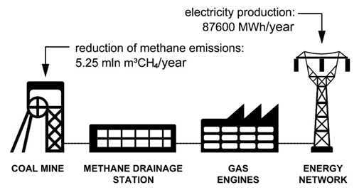
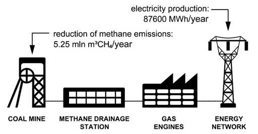
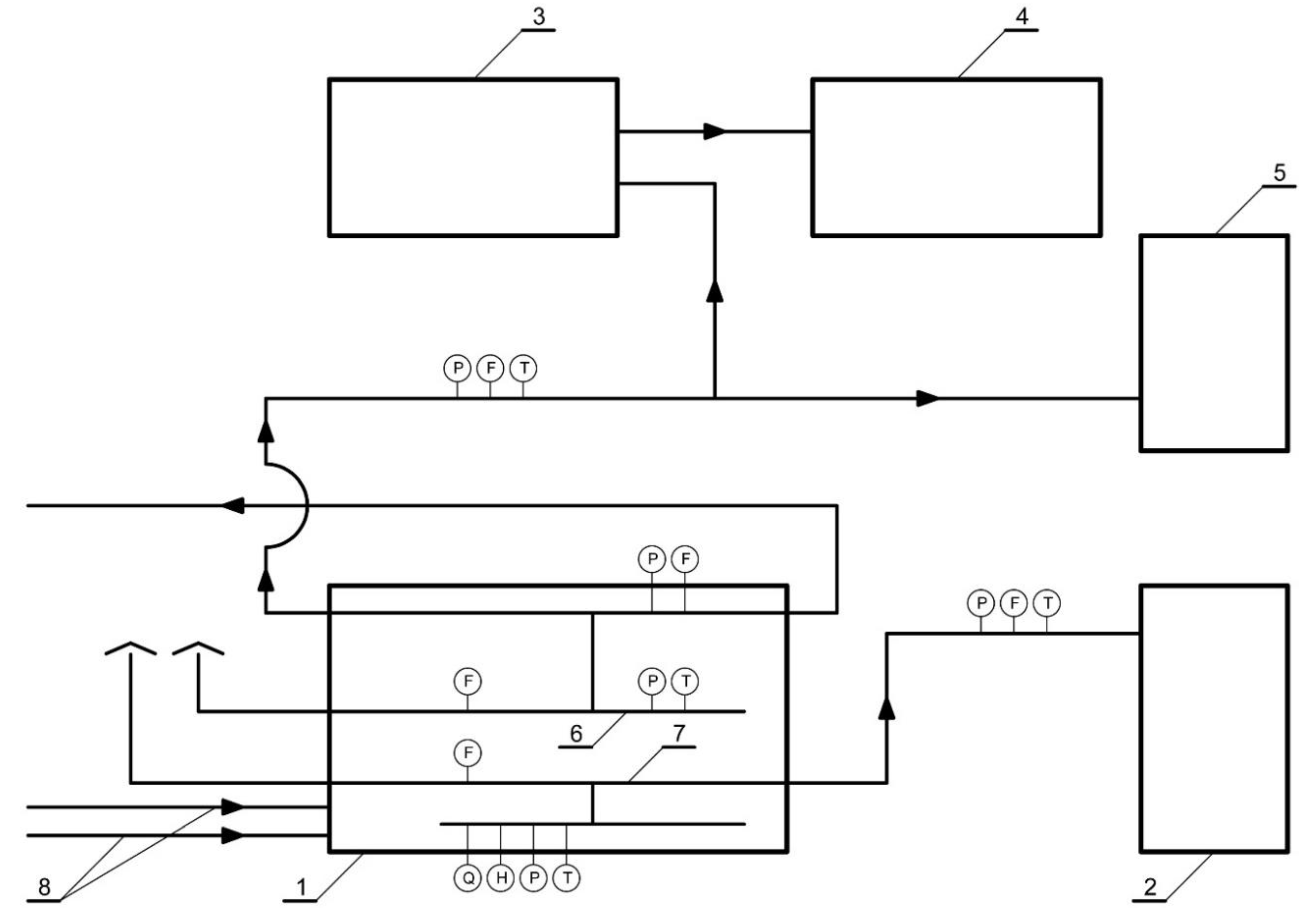
The combined energy and cooling system in the analyzed mine is used mainly for the purposes of central air-conditioning of the hard coal mine located in the Upper Silesian Coal Basin in southern Poland. It uses a comprehensive combination of electricity, heat, and cold as well as compressed air production using methane obtained from methane drainage. A simplified diagram of methane use together with marked measurement points of operating parameters (pressure, flowrate, temperature, moisture, and quality of methane–air mixture) is presented in
Figure 1.
The measurement of gas flowrate, temperature, and pressure is performed before each of the recipients of the mixture. In addition, the quality of gas (composition) and its moisture content are measured at the methane drainage station. The composition of the mixture is determined by the ABB NGC8203+ chromatograph, which detects the following components: methane, propane, ethane, CO, CO2, N2, O2, H2S, and H2. Information on the exact composition of the mixture is essential for the proper operation of gas engines, for which methane concentration of approximately 40% is required. The turbine flow meter CGT-02 G4000 PN16 with a measuring range of 320 ÷ 6500 m3/h and a measuring accuracy of 1% is used to measure the flowrate of gas transmitted to gas engines. Temperature and moisture measurement is provided by a temperature and moisture converter for EE30EX explosion hazard zone with relative moisture accuracy of ±1% RH (0 ÷ 90% RH) and ±2% RH (90 ÷ 100% RH) and by a temperature sensor Pt1000 class A. On the other hand, the pressure of the methane–air mixture is determined using a pressure converter PC-28 with a measuring range of 4 kPa ÷ 60 MPa.
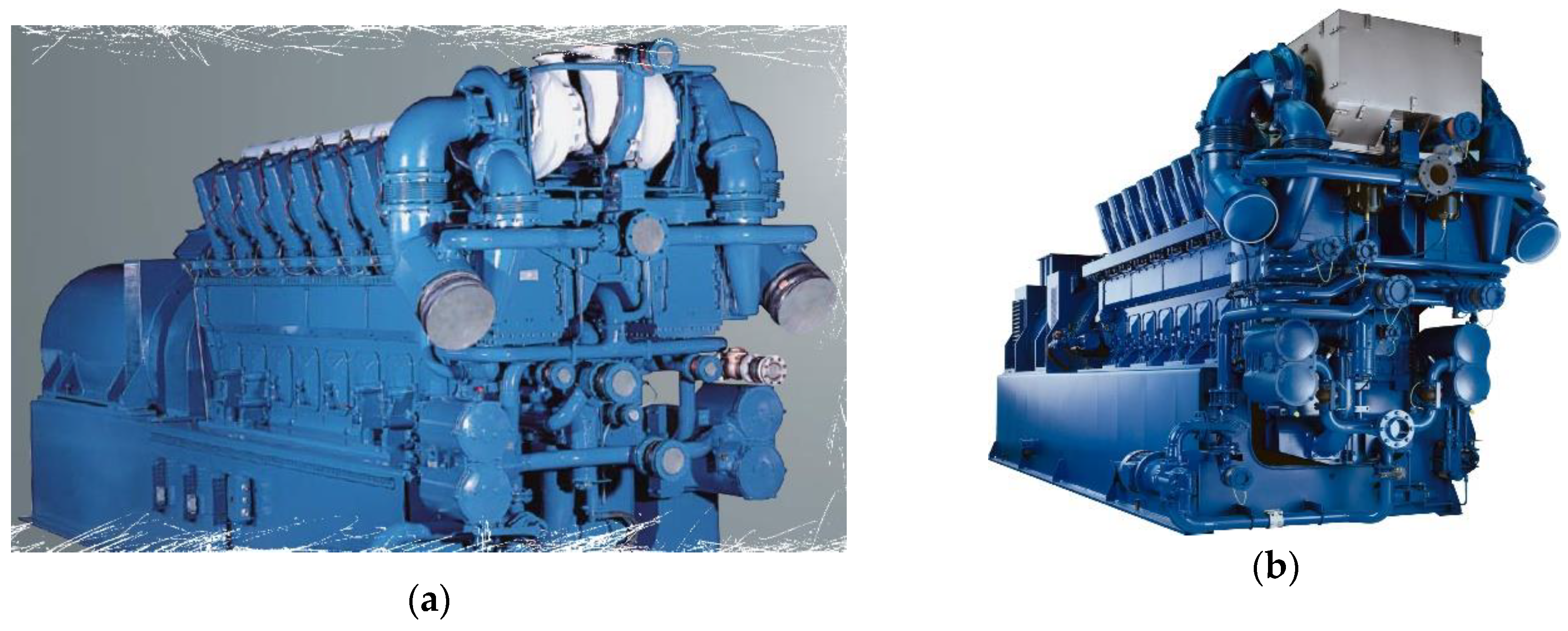
The system of using methane derived from methane drainage is based on four gas engines (2 × TBG 632 V16, 2 × TCG 2032 V16) with a total electrical power of 14.3 MWe.
Figure 2 shows the gas engines used [
27,
28].
3. Analysis of the Operating Parameters of Gas Engines in the Context of Methane Capture
Due to the specific nature of mining operations, there is a variability in the amount of captured methane and its concentration, which directly affects the operation of gas engines.
Figure 3,
Figure 4,
Figure 5 and
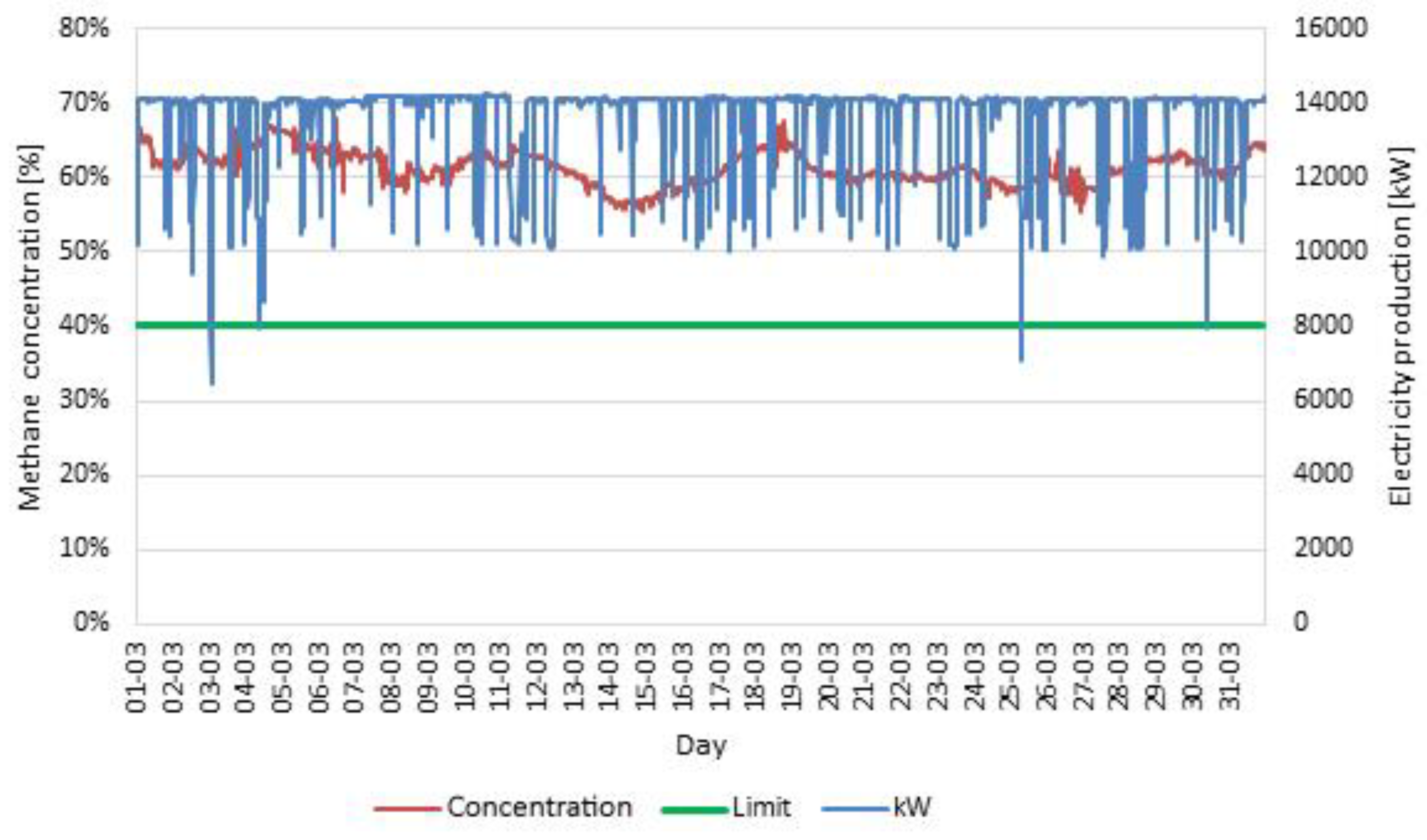
Figure 6 show the monthly operating parameters of the system while maintaining a sufficiently high methane concentration. Methane concentration in the captured methane–air mixture and electricity production in March is shown in
Figure 3.
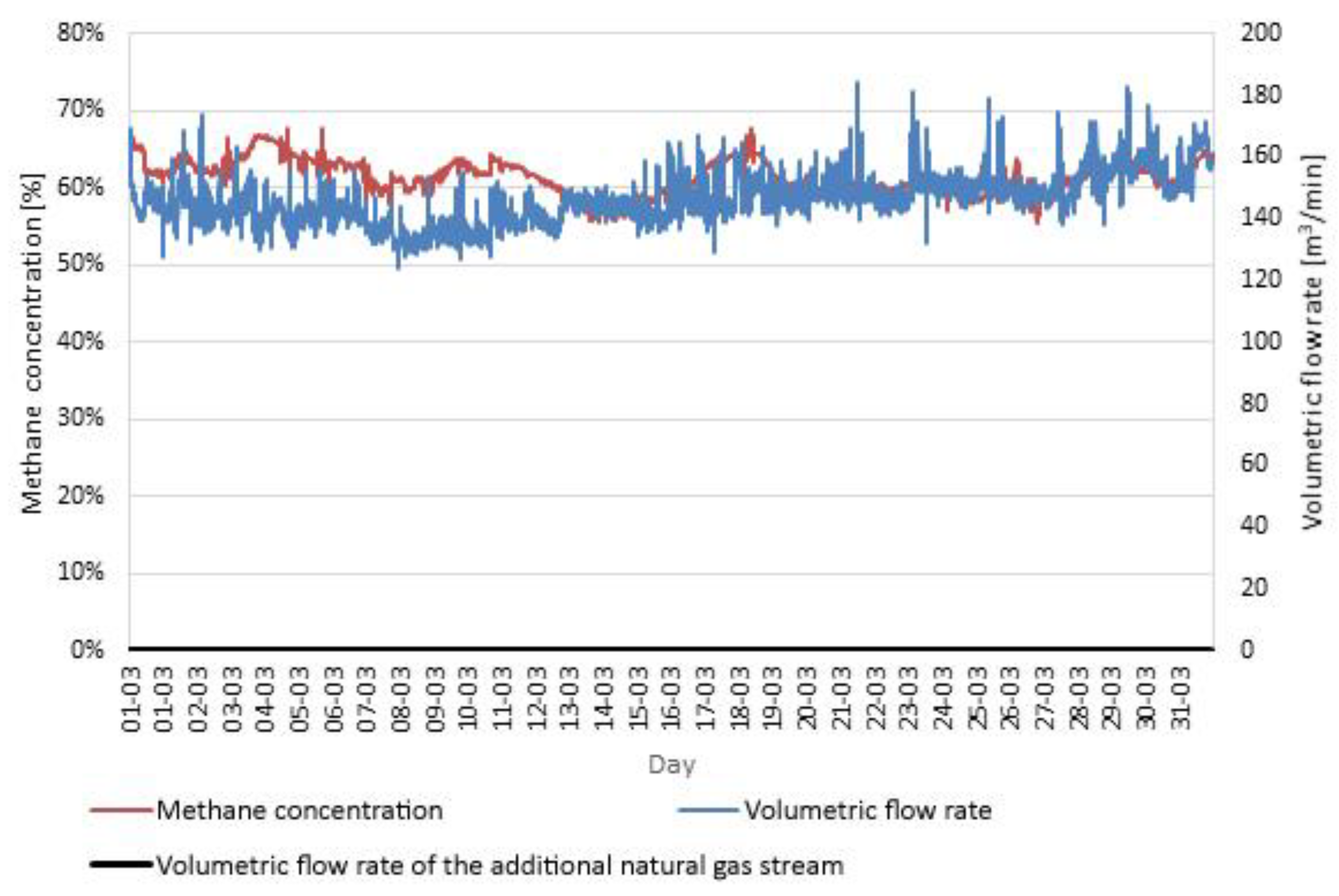
Figure 4 shows the variation of methane concentration and flowrate for the same month. The figure also shows the possible natural gas flowrate required to achieve the required mixture concentration of 40%.
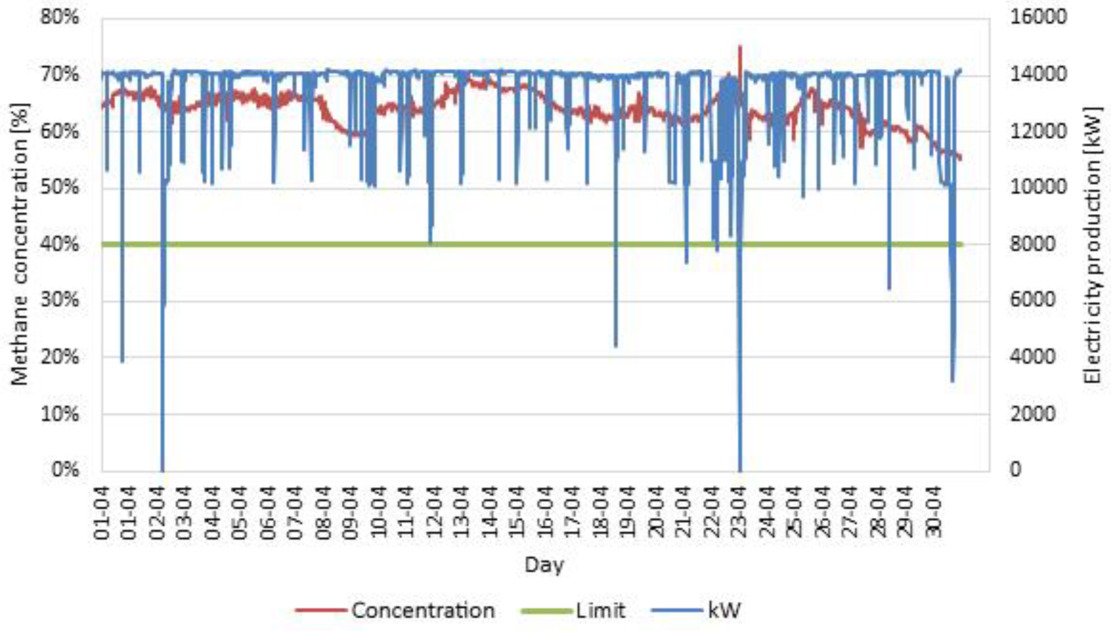
In the analyzed month, both the concentration of captured methane and its flowrate were at a sufficiently high level, which ensured stable operation of gas engines and electricity production of up to 14 MW. Similar results were obtained in the following month—April.
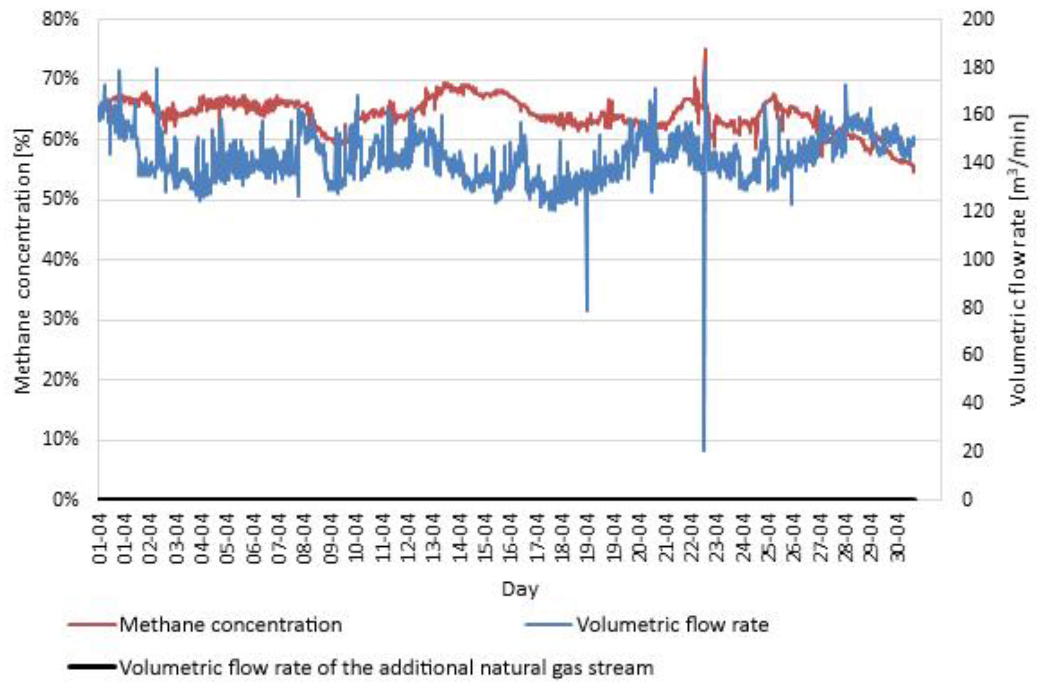
Figure 5 shows the concentration and production of electricity, while
Figure 6 shows the concentration and flowrate of the captured methane.
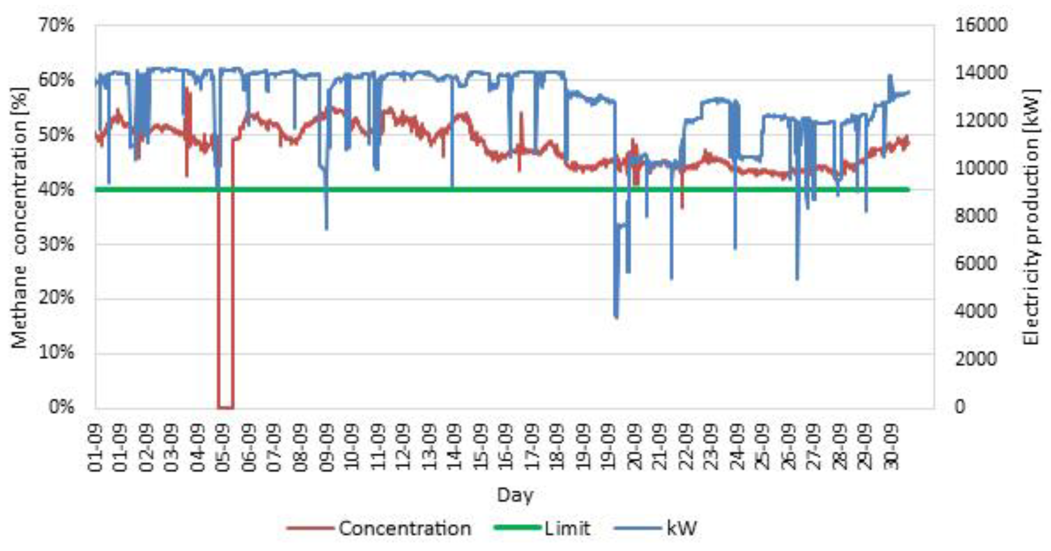
The first problems with the preservation of methane concentration appeared in September—
Figure 7. Most importantly, a decrease in concentration can be observed during the whole month, first to a value of about 50% and from the middle of the month close to the limit value of 40%.
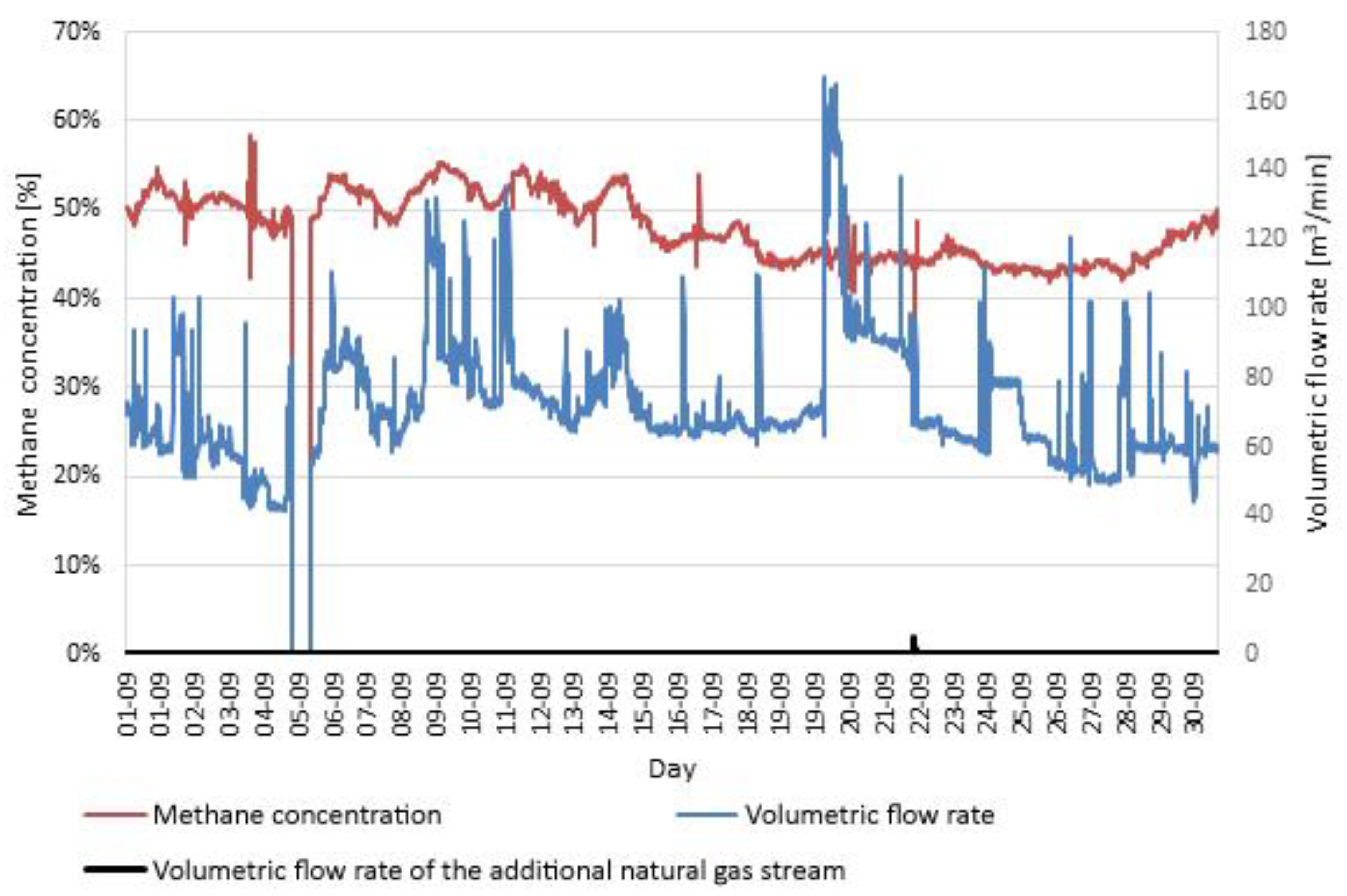
Particularly large fluctuations can be observed in the stream of the captured gas—
Figure 8. Such fluctuations have a negative impact on electricity production and can cause the failure of gas engines.
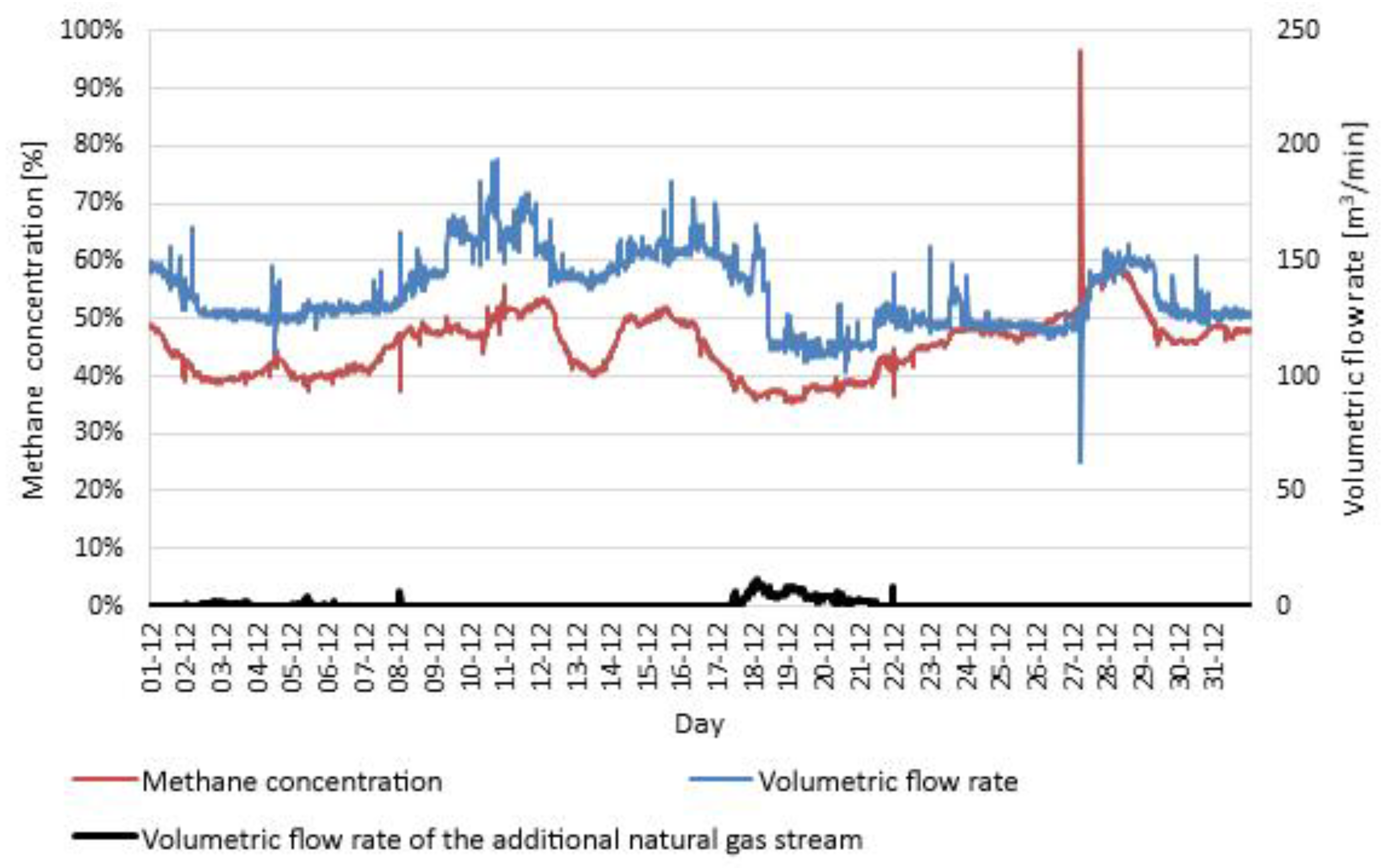
The most unfavorable parameters of the system operation were observed in December—
Figure 9. Methane concentration was much lower than 40%, which significantly reduced the volume of electricity production.
Low concentrations and fluctuations in the gas stream cause unstable operation of gas engines. In order to obtain the required concentration of 40%, an additional natural gas stream can be used—
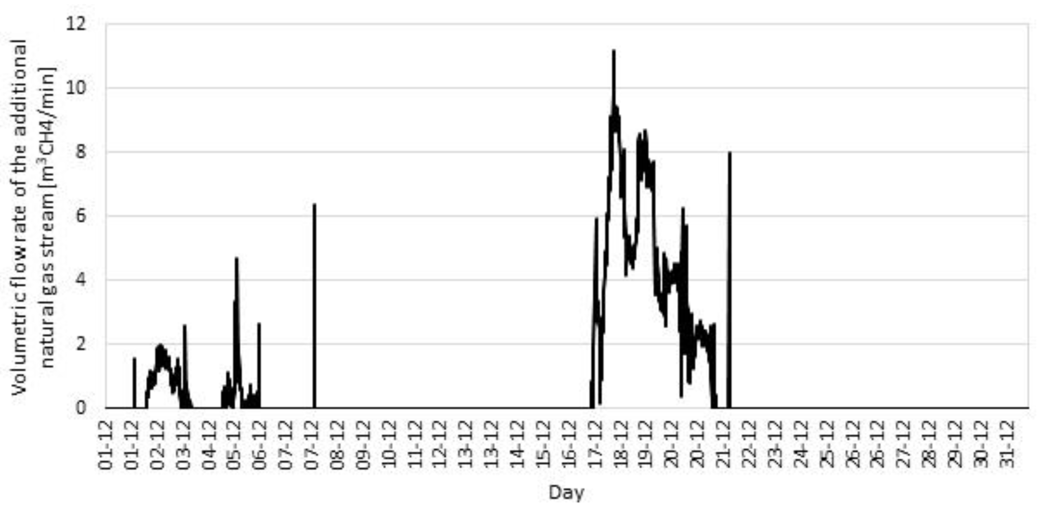
Figure 10. The volume of the additional natural gas stream is shown in
Figure 11.
Analyzing the operation of gas engines throughout the year, it was found that the natural gas stream needed to stabilize the methane concentration would amount to a maximum of 16 m3CH4/min. Fluctuations in the concentration and the stream of gas in September and subsequent months resulted from mining operations. Its share in the total methane capture of the mine gradually decreased from 29% in October, through 26% in November to 0% in December. In order to maintain stable operation, it is necessary for the methane drainage system to capture at least 50 m3CH4/min with a minimum concentration of 50%. It is not possible to supplement the stream by capturing methane before and after exploitation because these are too small amounts of methane streams to be obtained. It is therefore necessary to consider other methods of stabilizing the concentration and stream of the captured methane–air mixture.
Table 1 shows a statistical summary of the analyzed parameters in individual months. Basic stats (mean, median, confidence interval, minimum, and maximum) were used to describe the measured parameters. The variability and decreasing methane content and concentration in the following months are expressed. Narrow confidence intervals indicate stable operation of gas engine installations. However, looking at the minimum values, it can be seen that there were interruptions in the production of electricity.
It should be added that the technology of obtaining methane from coal seams for the purposes of generating electricity and heat from hard coal mines will be a thing of the past. Currently obtained energy from methane is used for the needs of the company. However, after mining exploration, methane can be used for the needs of the local community.
4. Analysis of the Possibility of Obtaining a Higher Methane Concentration for Gas Engines
Stabilization of the parameters of the methane–air mixture can be achieved by means of a number of methods. However, in order to avoid high costs of such processes, it is necessary to focus on improving the standards of methane capture from the rock mass. The basic methods of improving the quality of gas include:
Purifying mine gas
Mixing mine gas with CNG gas
Mixing mine gas with natural gas from a low-pressure ground tank
Capturing and using an additional gas stream of high methane concentration from tanks from already excavated areas
4.1. Purifying Mine Gas
During the purification of the gas from the methane drainage process, nitrogen, oxygen, carbon dioxide, carbon monoxide, and hydrogen sulphide are removed from its composition. The basic process used for this purpose is pressure swing adsorption (PSA). A typical solution is to produce gas with a methane concentration of approximately 95% [
29]. Various configurations of the PSA cycle have been developed, usually consisting of multi-stage processes. The number of components present in the methane drainage mixture requires a combination of processes to obtain a high concentration of methane. Pressure swing adsorption has been described in detail in many studies, mainly in the field of chemistry, often in relation to biogas quality improvement—e.g., [
30,
31,
32]. One of the modifications of the pressure swing adsorption is the vacuum pressure swing adsorption (VPSA) method, which consists of several stages: filling the sorption column with an methane–air mixture, adsorption of components, washing out the non-absorbed elements with an enriched product, two-stage, low pressure desorption of methane. A diagram of such an installation is shown in
Figure 12.
The conducted studies allowed to obtain gas enriched with 96–98% methane from the methane–air mixture with methane content of 55.2% [
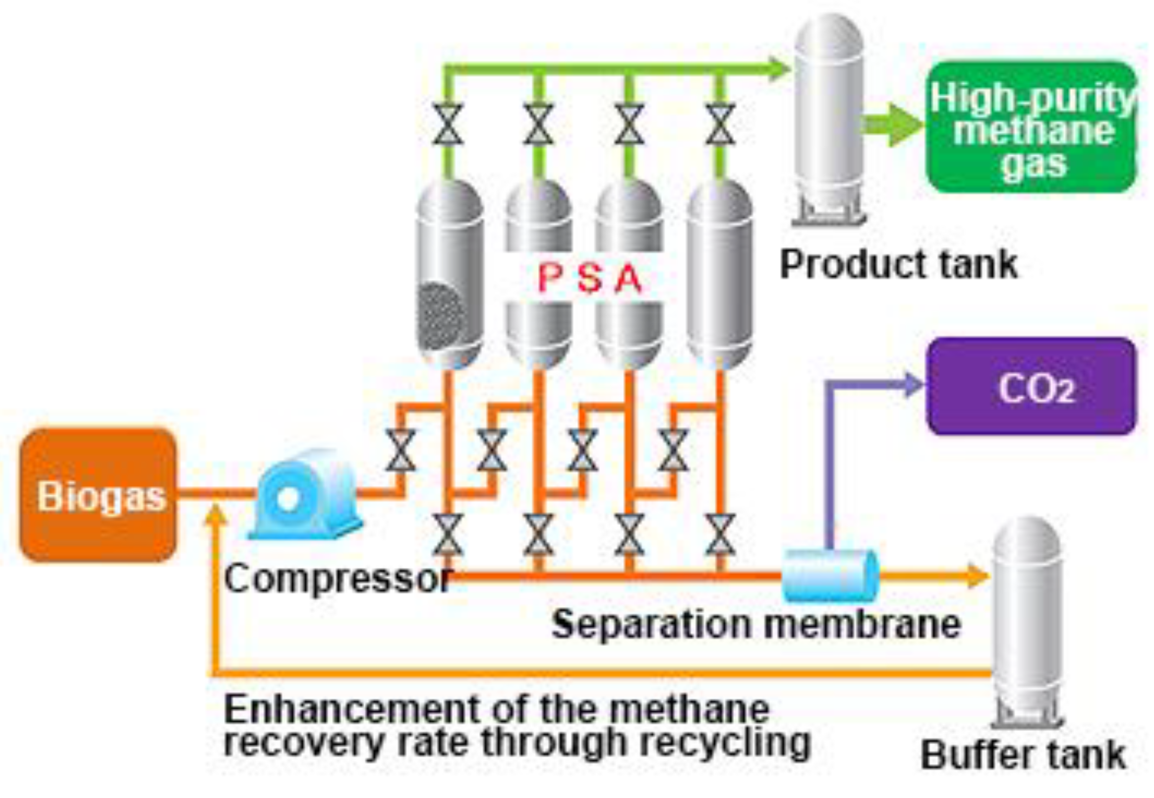
33]. The PSA method is still being improved by making various modifications, such as using new sorbents or combining several methods of gas purification into one system. Such combination seems to achieve the best results. Osaka Gas combined the PSA technology and membrane separation, which achieved a methane concentration of more than 99% for a biogas [
34]. A simplified diagram of such an installation is shown in
Figure 13.
Other methods used to purify gas from methane drainage are [
29]:
Molecular sieve adsorption—a PSA variant with a regulated molecular sieve
Cryogenic separation—uses multiple heat exchangers to liquefy the high-pressure supply gas stream. It is characterized by a high degree of purification (up to 98%)
Methods of purification are characterized by very high efficiency and are already used in many branches of industry, also for the purification of gas from mine methane draining. However, due to a very high investment cost, the use of such a solution of gas purification for gas engines is in this case not economically justified.
4.2. Mixing Mine Gas with CNG Gas
The maintenance of the required methane concentration can be achieved by using the compressed natural gas (CNG) system to mix CNG with the methane-drained gas. The CNG would be added to obtain a mixture containing at least 50% of methane. Analyses indicate that such a process would be carried out in the period from a few to a dozen or so weeks during the year. Compression of the CNG requires the use of suitable devices to draw heat from the combustion of a part of the compressed gas or from the air. The location of the mixing station and gas tanks is very important. The best place to locate a station for mixing the CNG with the methane drainage gas is the vicinity of a station, where the capture of methane from the rock mass occurs. Before approving the assumed location on the premises of the mining plant, the categories and the scope of explosion hazard zones should be determined in accordance with the standard: PN-EN 1127–1:2001 “Explosive atmospheres. Explosion prevention and protection” and classify hazardous areas in accordance with the standard: PN-EN 60079–10:2003 “Electrical equipment in potentially explosive atmospheres. Classification of hazardous areas”. Consideration should be given to existing land development and explosion hazard zones.
The applied solution essentially secures the maintenance of the required methane concentration for the undisturbed operation of gas engines and makes itself independent from the obtained concentrations and gas streams from the underground capture in hard coal mines. In order to eliminate commercial gas production, consideration should be given to the supply of gas from the mine’s available intakes, which should be preceded by an appropriate analysis.
4.3. Mixing Mine Gas with Natural Gas from a Low-Pressure Ground Tank
In order to become independent from changes in atmospheric pressure, it is proposed to build a permanent natural gas tank. The gas from the methane tank would be extracted in cases where the concentration falls below the required level. The system will automatically add gas to the methane drainage mixture, in order to correct the levels (concentrations) of methane. A 1500 m
3 tank located close to the methane drainage station will be sufficient. As a low-pressure tank, it does not require any special equipment to expand the gas. Such solutions are widely used in biogas installations as well as in mines [
36]. If such a solution was applied, the required works would include:
Construction of reinforced concrete foundations for the tank;
Installation of a two-layer biogas tank with a capacity of 1500 m3;
Construction of technological, electrical, control, measurement, and automation installations, as well as systems of dewatering biogas pipelines;
Construction of a container biogas distribution and measurement station on the reinforced concrete foundations;
Performance of leakage tests and final tests.
The application of such a solution is much cheaper than the purification technology. Additionally, the tank can store methane from methane drainage in periods of increased capture and use it to make up for gas shortages in periods of reduced capture, or in case of methane concentration drop. It eliminates the costs associated with the purchase of natural gas.
4.4. Using the Capture of an Additional Gas Stream of High Methane Concentration from Already Excavated Areas
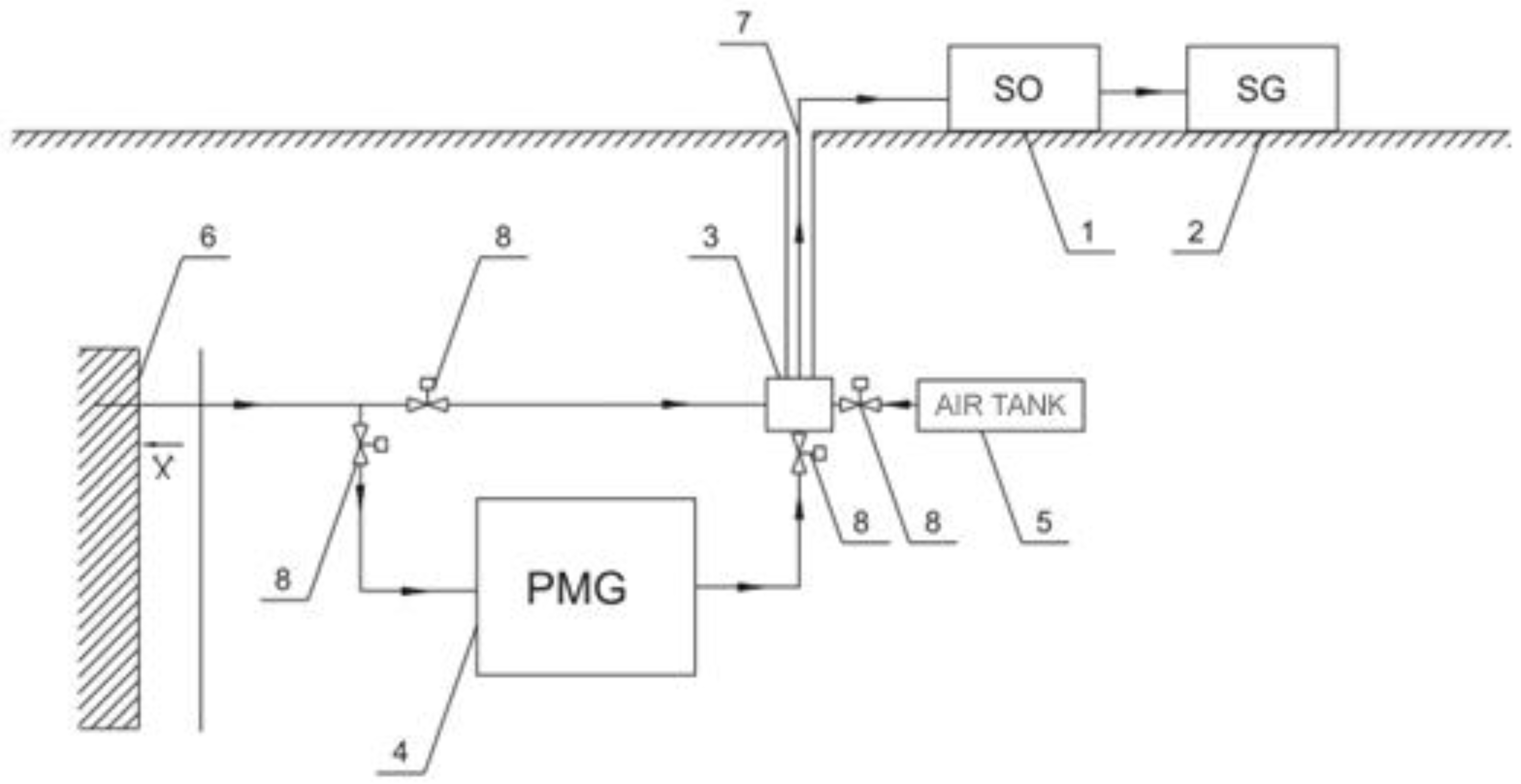
To ensure a stable capture of the methane–air mixture, it is also possible to use the capture of methane from excavated coal seams. The idea of this solution is shown in
Figure 14. The proposed tank would have a capacity of approximately 3 million m
3 and would be used to store the surplus of methane from methane drainage. The system requires the use of an automatic regulation system allowing to correct the levels (concentrations) of gas streams captured at the methane drainage station.
From a theoretical point of view, such a system is feasible to implement. The main problem is to ensure the tightness of the rock mass acting as a tank. Since all underground sources of methane capture are a system of ‘connected vessels’, it is doubtful whether the capture is reliable in terms of methane concentration and stream. The use of such tanks could only be carried out periodically. Control of methane inflow from tanks with high methane concentrations could not maintain the required amount and concentration in the gas fed to gas engines, which is caused by difficulties in regulating the methane drainage network.
5. Conclusions
The analysis of the operation of the methane capture station with respect to appropriate concentrations and streams of captured gas from methane drainage and the review of possible solutions improving the quality of the captured gas allowed us to present the following conclusions, that in order to maintain the methane concentration above the assumed value of 40%, the flowrate of gas from the capture of methane in the amount of not less than 50 m3CH4/min with a minimum concentration of 50% should be ensured. It ensures that the required methane concentration in the fuel mixture for gas engines is maintained. Other sources of methane capture, i.e., before or after exploitation sources shall be no more than complementary and shall not constitute the primary source of the methane–air mixture for gas engines.
The analysis of methane capture in particular months shows that the methane drainage station captured gas at the level of approx. 150 m3/min in the period from January to July. At that time, the stream of captured methane from the areas of exploitation was about 75 m3/min, which constitutes half of the mixture at the methane drainage station. From August to November, a decrease of about half of the captured gas is observed. Analyzing data from methane capture, it is difficult to indicate the reason for such a state, except for the reduction of methane stream captured from exploitation.
The use of a methane–air mixture purification system to obtain high methane concentrations is not economically justified due to very high investment costs.
The use of systems of mixing compressed natural gas CNG with the gas from methane drainage of the mine essentially ensure that the required methane concentration is maintained for the undisturbed operation of gas engines. In order to eliminate commercial gas production, consideration should be given to the supply of gas from the mine’s available intakes.
The use of underground methane tanks requires the identification of conditions, and the execution of a project, including the determination of the amount of methane and the time of its exploitation. It is possible for a certain period of time, however, the difficulty in obtaining the required methane concentration eliminates this system of supplying the methane–air mixture to the methane drainage station.
The optimal solution seems to be a system with a tank collecting methane from the methane drainage system at the methane drainage station. Due to its limited capacity, it ensures the operation of engines for several days. However, this solution is technically simple and inexpensive compared to other solutions. Additionally, it allows the use of the methane captured by methane drainage installations, which eliminates the costs associated with the purchase of gas.
In Europe, the reduction of fossil fuel extraction is related to climate policy. However, in areas where mining has been actively conducted in the past, despite the long-term mining of coal seams, large reserves of methane remain. After the end of mining activity, it is reasonable and possible to continue to take methane from the rock mass. Of course, the quantitative approach to methane will decrease, but the quality of methane fuel will increase. Methane fuel can be successfully used as dispersed unconventional sources of electricity and heat. Therefore, methane could be treated as a renewable energy source. In the area of Upper Silesia, there are known cases of stable intake of methane mixture over a very long period of time.
Author Contributions
Conceptualization, M.B. and J.C.; Methodology, M.B.; Software, M.K.; Validation, M.K., R.Ł., and J.C.; Formal analysis, P.Ż.; Investigation, M.B.; Resources, M.B.; Data curation, R.Ł.; Writing—original draft preparation, M.K.; Writing—review and editing, R.Ł.; Visualization, P.Ż.; Supervision, M.B.; Project administration, P.Ż.; Funding acquisition, M.B. All authors have read and agreed to the published version of the manuscript.
Funding
This research received no external funding.
Conflicts of Interest
The authors declare no conflict of interest.
Nomenclature
| C | Methane concentration, % |
| Ep | Electricity production, kW |
| F | Volumetric flowrate of gas, m3/min |
| H | Relative humidity of gas, % |
| P | Pressure of the methane–air mixture, kPa |
| T | Temperature of gas, °C |
Acronyms
| CMM | Coal mine methane/methane drainage |
| CNG | Compressed natural gas |
| GE | Gas engine/turbines |
| GHG | Greenhouse gas |
| PSA | Pressure swing adsorption |
| TFRR | Thermal flow reversal reactor |
| VAM | Ventilation air methane |
| VPSA | Vacuum pressure swing adsorption |
References
- IPCC. Climate Change 2014: Synthesis Report. Contribution of Working Groups I, II and III to the Fifth Assessment Report of the Intergovernmental Panel on Climate Change; Core Writing Team, Pachauri, R.K., Meyer, L.A., Eds.; IPCC: Geneva, Switzerland, 2014; 151p. [Google Scholar]
- USEPA. Global Anthropogenic Non-CO2 Greenhouse Gas Emissions: 1990–2030; USEPA 430-S-12-002; USEPA: Washington, DC, USA, 2012.
- UNECE. Best Practice Guidance for Effective Methane Drainage and Use in Coal Mines, 2nd ed.; ECE Energy Series No. 47; United Nations: Geneva, Switzerland, 2016; ISBN 978-92-1-117121-1. Available online: https://www.unece.org/fileadmin/DAM/energy/cmm/docs/BPG_2017.pdf (accessed on 16 April 2019).
- Karacan, C.Ö. Modeling and prediction of ventilation methane emissions of U.S. longwall mines using supervised artificial neural networks. Int. J. Coal Geol. 2008, 73, 371–387. [Google Scholar] [CrossRef]
- Su, S.; Han, J.; Wu, J.; Li, H.; Worrall, R.; Guo, H.; Sun, X.; Liu, W. Fugitive coal mine methane emissions at five mining areas in China. Atmos. Environ. 2011, 45, 2220–2232. [Google Scholar] [CrossRef]
- Ji, Z.-M.; Chen, Z.-J.; Pan, J.-N.; Niu, Q.-H. A novel method for estimating methane emissions from underground coal mines: The Yanma coal mine, China. Atmos. Environ. 2017, 170, 96–107. [Google Scholar] [CrossRef]
- Feng, G.R.; Zhang, A.; Hu, S.Y.; Cheng, J.W.; Miu, X.Y.; Hao, G.C.; Han, D.D.; Guan, S.W.; Zhao, G.Z. A methodology for determining the methane flow space in abandoned mine gobs and its application in methane drainage. Fuel 2017, 227, 208–217. [Google Scholar] [CrossRef]
- Nawrat, S.; Kuczera, Z.; Łuczak, R.; Życzkowski, P.; Napieraj, S.; Gatnar, K. Utylizacja Metanu Z Pokładów Węgla W Polskich Kopalniach Podziemnych; Uczelniane Wydawnictwa Naukowo-Dydaktyczne AGH: Kraków, Poland, 2009. [Google Scholar]
- Cheng, Y.-P.; Wang, L.; Zhang, X.-L. Environmental impact of coal mine methane emissions and responding strategies in China. Int. J. Greenh. Gas Control 2011, 5, 157–166. [Google Scholar] [CrossRef]
- Karacan, C.Ö.; Ruiz, F.A.; Cotè, M.; Phipps, S. Coal mine methane: A review of capture and utilization practices with benefits to mining safety and to greenhouse gas reduction. Int. J. Coal Geol. 2011, 86, 121–156. [Google Scholar] [CrossRef]
- Zhang, Y.; Doroodchi, E.; Moghtaderi, B. Utilization of ventilation air methane as an oxidizing agent in chemical looping combustion. Energy Convers. Manag. 2014, 85, 839–847. [Google Scholar] [CrossRef]
- Zhou, F.; Xia, T.; Wang, X.; Zhang, Y.; Sun, Y.; Liu, J. Recent developments in coal mine methane extraction and utilization in China: A review. J. Nat. Gas Sci. Eng. 2016, 31, 437–458. [Google Scholar] [CrossRef]
- Singh, H.; Mallick, J. Utilization of Ventilation Air Methane in Indian Coal Mines: Prospects and Challenges. Procedia Earth Planet. Sci. 2015, 11, 56–62. [Google Scholar] [CrossRef]
- Singh, A.K.; Kumar, J. Fugitive methane emissions from Indian coal mining and handling activities: Estimates, mitigation and opportunities for its utilization to generate clean energy. Energy Procedia 2016, 90, 336–348. [Google Scholar] [CrossRef]
- Pengfei, G. Development and present situation of utilization technology of Ventilation air methane (VAM) enrichment and utilization. In Proceedings of the 4th International Conference on Energy Equipment Science and Engineering, Xi’an, China, 28–30 December 2018. [Google Scholar]
- Li, Q.; Lin, B.; Yuan, D.; Chen, G. Demonstration and its validation for ventilation air methane (VAM) thermal oxidation and energy recovery project. Appl. Therm. Eng. 2015, 90, 75–85. [Google Scholar] [CrossRef]
- Yang, X.; Liu, Y.; Li, Z.; Zhang, C.; Xing, Y. Vacuum Exhaust Process in Pilot-Scale Vacuum Pressure Swing Adsorption for Coal Mine Ventilation Air Methane Enrichment. Energies 2018, 11, 1030. [Google Scholar] [CrossRef]
- Lan, B.; Li, Y.-R.; Zhao, X.-S.; Kang, J.-D. Industrial-Scale Experimental Study on the Thermal Oxidation of Ventilation Air Methane and the Heat Recovery in a Multibed Thermal Flow-Reversal Reactor. Energies 2018, 11, 1578. [Google Scholar] [CrossRef]
- Su, S.; Agnew, J. Catalytic combustion of coal mine ventilation air methane. Fuel 2006, 85, 1201–1210. [Google Scholar] [CrossRef]
- Karakurt, I.; Aydin, G.; Aydiner, K. Mine ventilation air methane as a sustainable energy source. Renew. Sustain. Energy Rev. 2011, 15, 1042–1049. [Google Scholar] [CrossRef]
- Gosiewski, K.; Pawlaczyk, A. Catalytic or thermal reversed flow combustion of coal mine ventilation air methane: What is better choice and when? Chem. Eng. J. 2014, 238, 78–85. [Google Scholar] [CrossRef]
- Kirchgessner, D.A.; Masemoreb, S.S.; Piccot, S.D. Engineering and economic evaluation of gas recovery and utilization technologies at selected US mines. Environ. Sci. Policy 2002, 5, 397–409. [Google Scholar] [CrossRef]
- Su, S.; Beath, A.; Guo, H.; Mallett, C. An assessment of mine methane mitigation and utilisation technologies. Prog. Energy Combust. Sci. 2005, 31, 123–170. [Google Scholar] [CrossRef]
- CoMeth. Coal Mine Methane—New Solutions for Use of CMM—Reduction of GHG Emissions. Final Publishable Summary Report FP7 Project No. TREN/FP7/EN/218935. Available online: https://www.cometh.info/downloads/218935_CoMeth_Final_publishable_summary_report_051212.pdf (accessed on 16 April 2019).
- Brinkmann, T.; Scholles, C.; Wind, J.; Wolff, T.; Dengel, A.; Clemens, W. Processing of coal mine gas with low methane concentrations for use in high-temperature fuel cells. Desalination 2008, 224, 7–11. [Google Scholar] [CrossRef][Green Version]
- Borowski, M.; Łuczak, R.; Życzkowski, P. Increase of methane intake through methane intake system with drainage excavation during longwall mining operations on a selected example. In Archives of Mining Sciences; Wydawnictwo Instytutu Mechaniki Górotworu PAN: Kraków, Poland, 2019; pp. 81–92, ISSN 0860-7001; ISBN 978-83-953913-2-3. [Google Scholar]
- DEUTZ, TBG632. The Gas Engine. 0031 1928/04/99/MM-V. Available online: http://www.alborzgenerator.com/images/docs/used-power-plant/3x3.1-9.3mw-deuts-2011-09-06/632gen.pdf (accessed on 18 September 2019).
- DEUTZ, Deutz Power Systems TCG2032. Version 05/06/E. Available online: http://www.powerplant-service.com/uploads/1503546667.pdf (accessed on 18 September 2019).
- USEPA. Upgrading Drained Coal Mine Methane to Pipeline Quality: A Report on the Commercial Status of System Suppliers; EPA Publication: EPA-430-R08-004; Coalbed Methane Outreach Program U. S. Environmental Protection Agency: Washington, DC, USA, 2008.
- Riboldi, L.; Bolland, O. Overview on Pressure Swing Adsorption (PSA) as CO2 capture technology: State-of-the-art, limits and potentials. Energy Procedia 2017, 114, 2390–2400. [Google Scholar] [CrossRef]
- Angelidaki, I.; Treua, L.; Tsapekosa, P.; Luoc, G.; Campanarob, S.; Wenzeld, H.; Kougiasa, P.G. Biogas upgrading and utilization: Current status and perspectives. Biotechnol. Adv. 2018, 36, 452–466. [Google Scholar] [CrossRef] [PubMed]
- Pullumbi, P.; Brandani, F.; Brandani, S. Gas separation by adsorption: Technological drivers and opportunities for improvement. Curr. Opin. Chem. Eng. 2019, 24, 131–142. [Google Scholar] [CrossRef]
- Olajossy, A.; Gawdzik, A.; Budner, Z.; Dula, J. Methane Separation from Coal Mine Methane Gas by Vacuum Pressure Swing Adsorption. Chem. Eng. Res. Des. 2003, 81, 474–482. [Google Scholar] [CrossRef]
- Osaka Gas. Biogas Upgrading System. Commercialization Project in Thailand. Available online: www.osakagas.co.jp/en/company/enterprise_future/article6/ (accessed on 03 October 2019).
- Osaka Gas. Harmonizing with the Environment and Contributing to Realizing a Sustainable Society. Available online: www.osakagas.co.jp/csr_e/charter02/technology.html (accessed on 3 October 2019).
- Borowski, M.; Kuczera, Z.; Chudy, J. Pro-ecological use of methane from methane drainage for the production of electricity and heat. Inż. Miner. J. Pol. Miner. Eng. Soc. 2018, 255–261. Available online: http://www.potopk.com.pl/Full_text/2018_full/IM%201-2018-a38.pdf (accessed on 1 October 2019). [CrossRef]
- Nawrat, S.; Kuczera, Z.; Łuczak, R.; Życzkowski, P. Problemy zapewnienia stabilnych parametrów paliwa z odmetanowania kopalń stosowanego do silników gazowych. Gór. i Geoinżynieria 2006, 30, 19–35. [Google Scholar]
© 2019 by the authors. Licensee MDPI, Basel, Switzerland. This article is an open access article distributed under the terms and conditions of the Creative Commons Attribution (CC BY) license (http://creativecommons.org/licenses/by/4.0/).


