Abstract
Different alternatives are being studied nowadays in order to enhance the behavior of transcritical CO2 refrigeration plants. Among the most studied options, subcooling is one of the most analyzed methods in the last years, increasing cooling capacity and Coefficient Of Performance (COP), especially at high hot sink temperatures. A new cycle, called integrated mechanical subcooling cycle, has been developed, as a total-CO2 solution, to provide the subcooling in CO2 transcritical refrigeration cycles. It corresponds to a promising solution from the point of view of energy efficiency. The purpose of this work is to present, for the first time, thermodynamic analysis of a CO2 refrigeration cycle with integrated mechanical subcooling cycle from first and second law approaches. Using simplified models of the components, the optimum operating conditions, optimum gas-cooler pressure, and subcooling degree are determined in order to obtain the maximum COP. The main energy parameters of the system were analyzed for different evaporation levels and heat rejection temperatures. The exergy destruction was analyzed for each component, identifying the elements of the system that introduce more irreversibilities. It has been concluded that the new cycle could offer COP improvements from 11.7% to 15.9% in relation to single-stage cycles with internal heat exchanger (IHX) at 35 °C ambient temperature.
1. Introduction
The refrigeration sector has been highly altered in recent years due to the latest European directive [1] and other restrictions and protocols [2,3], which leave carbon dioxide as the only alternative for centralized commercial refrigeration because of its low Global Warming Potential (GWP) and its security characteristics (non-flammable nor toxic, A1 ASHRAE classification). However, CO2 working in classical refrigeration cycles has some inconveniences such as its low performance compared to systems working with other HydroFluoroCarbons (HFC) refrigerants. This is the reason that the greatest technological advances in the last years have been developed specifically in line with the search for solutions to improve the performance of this refrigerant in hot climates, where classical configurations do not perform well enough.
Some research lines have proposed the use of a parallel compressor in the system to improve the energy behavior. By simulation, Sarkar and Agrawal [4] have optimized three cycles with different architectures including parallel compression economization alone, parallel compression economization with subcooler, and multistage compression with flash gas bypass. The cycle with parallel compression economization reached improvements in COP of 47.3% in relation to the basis CO2 transcritical refrigeration cycle. Chesi et al. [5] experimentally showed the limits that present the parallel compressor in a real plant, which lead to increments in COP not as promising as the theoretical results. Also, the use of ejectors is widely studied as a way to improve CO2 installations either using multi-ejectors [6] or adjustable ejectors [7]. Even with the promising results of this solution, the operation and control remain complex.
The other great research line is focused on subcooling methods [8]. The purpose of subcooling methods is to subcool the CO2 at the exit of the gas-cooler, which increases the COP of the plant due to the increment on the specific cooling capacity, the reduction of the optimum working pressure, and the reduction of the specific compression work [9]. First, studies show that when the subcooling is higher, the increments are higher. However, not all the subcooling systems have the same performance, nor the same range of application. The improvements they can produce depend on the cost of the subcooling and on the working conditions. To obtain the greatest benefits of this type of system, they must be optimized in terms of pressure and subcooling degree to achieve maximum COP. In addition to the benefits that contribute to the energy efficiency of the plant, these systems also have benefits from an exergy analysis. The reduction of the optimum pressure and the subcooling allow for reducing the exergy destruction that takes place in the expansion process, leading to configurations with greater exergy performance.
The main subcooling methods are classified as internal methods and dedicated subcooling methods. The first studied method and widely applied in applications nowadays is the use of an internal heat exchanger (IHX). This heat exchanger produces a light subcooling of the CO2, which slightly improves its performance but also has some negative effects, which decrease that improvement, as it is the superheat produced at the suction line of the compressor [10].
Among the dedicated systems, the dedicated mechanical subcooling is a solution that involves the addition of a vapor compressor cycle that is combined with the CO2 cycle through a subcooler. This cycle is independent and can operate with other fluids different from CO2. The first theoretical studies, presented by Llopis et al. [9], show important improvements in COP by the use of the DMS when comparing it to a basic CO2 cycle. This study showed the existence of an optimum pressure and, evaluating different subcooling degrees, it was observed that the improvement was greater for the highest subcooling degree (10 K). Later, these results were corroborated experimentally, where increments up to 26.1% in COP and 39.4% in cooling capacity are obtained for 40 °C of heat rejection temperature and an evaporating level of 0 °C [11]. These experiments were optimized in terms of discharge pressure but the subcooling degree was not optimized. Sanchez et al. [12] also carried out tests in a smaller plant and compared them with the same system with IHX.
Dai et al. [13] studied a R152a DMS single-stage cycle optimizing gas-cooler pressure and subcooling degree, obtaining the best results at low evaporation levels and high heat rejection temperatures. The advantages of using zeotropic mixtures in the DMS cycle have also been analyzed [14] obtaining higher increments in COP due to the small heat transfer irreversibility that it generated directly related to the glide of the mixture.
The implementation of this cycle has also been experimentally studied for booster systems [15,16,17]. Nebot-Andrés et al. [18] compared the dedicated mechanical subcooling versus the cascade system concluding that the DMS is more energy efficient for warm climates considering annual operating times for applications whose evaporation level is greater than −15 °C. That is why subcooling systems are interesting for medium-temperature applications in hot climates where the temperature lift between the cold and heat sources is lower than 28.5 K.
Classified as an internal cycle, we found the integrated mechanical subcooling (IMS, Figure 1) that has some similarities with the DMS in its main characteristics. The subcooling is also reached thanks to a subcooler placed after the gas-cooler and performed by a vapor compressor cycle. The main difference is that the working fluid of the IMS is also CO2, extracted from the main cycle. Another benefit of this cycle is that it has less components than the DMS because it does not need a condenser because the CO2 is injected in the gas-cooler after the compression stage. This cycle therefore presents the same potential benefits of the DMS cycles, such as the improvement of the COP and the reduction of the entropy generation, but it only works with CO2 and its precise configuration requires a smaller number of components. This cycle is also similar to the parallel compression with an economizer presented by Sarkar and Agrawal [4], with the advantage of controlling gas-cooler pressure and useful superheat at the evaporator at the same time, allowing one to optimize the cycle.
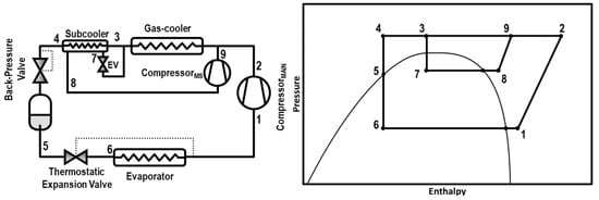
Figure 1.
Schematic diagram (left) and Ph diagram of the cycle (right).
The first time this cycle was presented was in the patent of Shapiro [19]. Then, Cecchinato et al. [20] theoretically evaluated this system obtaining promising increments in relation to the basic single-stage cycle. The cycle has also been studied by Qureshi and Zubair [21] but not for CO2 applications.
Catalán-Gil et al. [17] have compared both the integrated and the dedicated mechanical subcooling cycles in booster systems for supermarket applications, where the most favorable regions for the implementation of each of the systems are identified. They presented annual energy consumption reductions between 2.9% and 3.4% for warm countries and between 1.3% to 2.4% for hot regions by using the IMS. Nebot-Andrés et al. [22] also presented a theoretical comparison of both mechanical subcooling cycles, obtaining similar increments for both cycles in relation to the cycle with IHX but, at medium environment temperatures; the IMS cycle was more beneficial.
This work has been developed in order to analyze the benefits of energetic and exergetic performance of the integrated mechanical subcooling and also to study the behavior of this cycle for applications of medium temperature (evaporating levels between −15 °C and 5 °C) both in transcritical and subcritical conditions. It has been demonstrated the COP depends on the environment and application conditions, on the components, but also on the subcooling degree and gas-cooler pressure. The existence of optimal pressure and subcooling for when the COP is maximum has been demonstrated and these optimal conditions have been determined. In the same way, two correlations that allow the identification of these optimal parameters for this type of cycle are presented.
The results presented on the paper correspond to the evaluation a single-stage CO2 refrigeration cycle with integrated mechanical subcooling cycle, based on manufacturers data. The cooling capacity and COP of the cycle have been evaluated at five different evaporation levels (−15 °C, −10 °C, −5 °C, 0 °C, and 5 °C) and ambient temperatures between 15 °C and 40 °C, always for the optimum conditions of gas-cooler pressure and subcooling degree.
2. Integrated Mechanical Subcooling Cycle. Model Description
The integrated mechanical subcooling cycle is one of the subcooling methods that can be applied in CO2 systems and aims to subcool the CO2 at the exit of the gas-cooler to improve its energy behavior.
2.1. Description of the Cycle
The schema of this cycle is shown in Figure 1 as well as the Ph diagram of the cycle. The subcooling is performed at the subcooler, placed next to the gas-cooler, thanks to the extraction of a current of CO2 that is expanded and evaporated in the subcooler. Then, this CO2 is re-compressed by an auxiliary compressor and re-injected into the main circuit. This system can be configured in three different architectures; the extraction of the CO2 can be done from the exit of the gas-cooler, the exit of the subcooler, or from the liquid tank. In this work, the studied configuration is the one extracting from the gas-cooler exit.
2.2. First Law Approach: Thermodynamic Analysis
This section describes the thermodynamic model and assumptions used to simulate this cycle and to assess the critical parameters that influence the performance of the cycle for both operational modes, transcritical and subcritical. The thermodynamic model is based on REFPROP v.9.1. [23] for the thermo-physical properties of the fluid and it is calculated by assuming the following hypothesis:
- Environment temperatures from 15 °C to 40 °C are considered.
- Five evaporation levels are studied: 5 °C, 0 °C, −5 °C, 10 °C, and −15 °C.
- Steady-state conditions.
- No pressure drops are considered.
- The heat losses through the environment are neglected.
- Both compressors efficiencies are correlated based on manufacturer’s data, calculated as presented in Equation (1) and parameters from Table 1.
 Table 1. Performance data compressors obtained from manufacturers data.
 - Useful superheating is considered of 10 K at the main evaporator and 5 K at the subcooler in the low-pressure line.
- Subcritical conditions are always considered when the ambient temperature is lower than 24 °C and transcritical conditions when it is over 25 °C. Between these temperatures, both regimes are considered, selecting the one with better energy performance.
- The approach considered in the gas-cooler is 2 K for transcritical conditions due to the good thermal transfer of carbon dioxide at the supercritical region [24,25] while an approach of 5 K is considered for subcritical conditions.
- The efficiency of the subcooler is not considered to be constant. Its evaporation temperature is fixed considering a pinch between subcooler exit temperature and the evaporation temperature of 2 K for transcritical conditions and 5 K for subcritical conditions.
- The subcooling degree considered in the subcooler, defined as Equation (4), varies in order to optimize the system, as it is described in the following section.
- Both mass flows are related by the energy balance on the subcooler, being the mass flow of the IMS cycle defined by Equation (5) when working in nominal conditions.
- To obtain the desired value of subcooling degree, the IMS mass flow must be adapted by varying the compressor speed. A linear relation between the mass flow and the compressor velocity is considered to calculate the actual mass flow. The power consumption of the IMS compressor is also considered as linearly dependent on the compressor speed.
2.3. Second Law Approach: Exergy Analysis
The exergy analysis of the system is performed calculating the exergy destruction in each of the components of the cycle with the aim to identify where more irreversibilities are produced. The death state is considered as 0 °C and 1 bar. The exergy of a point is the difference between the enthalpy of the point and the enthalpy of the death state plus the product of the death state’s temperature and the difference between the entropy of the point and the entropy of the death state (Equation (8)).
- Exergy destruction at the compressors is calculated as shown in Equation (9) were is the work rate of the compressor.
- At the subcooler, the exergy destruction of both flows taking part in the heat transfer is considered (Equation (10)).
- In the expansion valves and the back pressure, it is calculated as the product of the mass flow circulating on the device and the difference between the exergy at the inlet and outlet of the component.
- At gas-cooler and evaporator, only the exergy destruction of the CO2 side is considered, as shown in Equations (12) and (13), respectively.
3. Performance Advantages of the IMS System
Subcooling at CO2 systems has several benefits on their performance. Specifically, the mechanical subcooling cycles allow for increasing the specific cooling capacity of the installation and reducing the optimum working pressure, which leads to a reduction in the specific compression work and, despite the addition of a second compressor, the overall COP of the cycle increases. Regarding the exergy losses of the system, the introduction of the subcooling also drifts in a reduction of the irreversibilities that take place in the expansion stage [8].
3.1. First Law
Comparing the CO2 refrigeration system with integrated mechanical subcooling to a single-stage refrigeration cycle with internal heat exchanger (IHX) from a first law analysis, the improvements of COP are clearly seen, due to the benefits named before.
Figure 2 shows the increment of COP obtained with the IMS compared to the cycle with IHX. As it can be seen, the increments are higher at high ambient temperatures, reaching increments of 40% for evaporation levels of −10 °C, which justifies the implementation of this system in warm and hot climates, due to its improved performance.
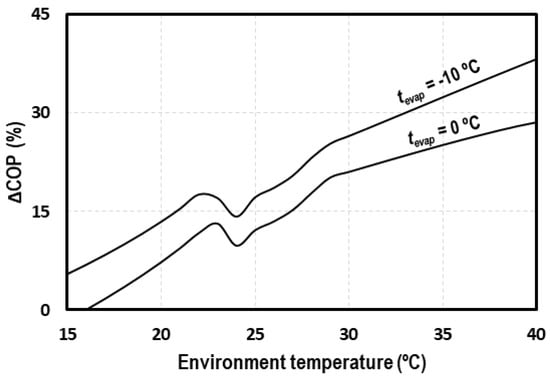
Figure 2.
COP increments due to the use of the integrated mechanical subcooling (IMS) cycle.
The comparison of the IMS to a classical CO2 system demonstrates the potential improvements that this system can introduce to transcritical CO2 cycles from an energy efficiency point of view.
3.2. Second Law
In this section, an exergy destruction analysis is performed. As it is presented by Llopis et al. [8], the introduction of the subcooling avoids some of the exergy losses that take place in the throttling processes, with this benefit being more important in transcritical conditions due to the reduction of the high pressure.
Figure 3 presents the T-s diagram of a transcritical CO2 system with internal heat exchanger (yellow) and with integrated mechanical subcooling (orange). The effect of the subcooling can clearly be observed, moving the inlet back-pressure point to the left and thus reducing the exergy losses in that stage. The reduction of the optimum working pressure also contributes to the reduction of the irreversibilities because the temperatures of the IMS are lower.
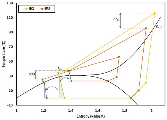
Figure 3.
T-s diagram of a transcritical CO2 system with internal heat exchanger (IHX) (yellow) and with IMS (orange) at tevap = 0 °C and tenv = 35 °C.
The implementation of the IMS also produces an increment in the cooling capacity of the cycle. To compare the exergy destruction of this system to the cycle with internal heat exchanger, it is necessary to refer the exergy destruction to the cooling capacity of the analyzed cycle.
Figure 4 represents the contribution of each of the components of the system to the exergy destruction divided by the total cooling capacity of the system. The exergy destruction on the gas-cooler represents 56%; 21% comes from the compressor, 7% from the expansion valve, 5% of the back pressure, and 4% corresponds to the expansion in the IMS cycle. Only 4% is produced on the IMS compressor, 2% on the subcooler, and 1% on the evaporator. The main irreversibilities are produced in the gas-cooler and the compressor. However, extracting a part of the CO2 and subcooling the rest allows reducing the irreversibilities produced on the expansion stage because the mass flow is smaller and the temperature at the entrance of the expansion device is lower. The additional compressor, the IMS expansion valve, and the subcooler are elements that introduce irreversibilities to the system. However, the reduction obtained because of the pressure reduction and the subcooling leads to a total exergy destruction per cooling capacity unit lower than that produced in the system with IHX. It is for these reasons that the IMS is a very interesting system from the point of view of exergy performance for the application in warm and hot climates.
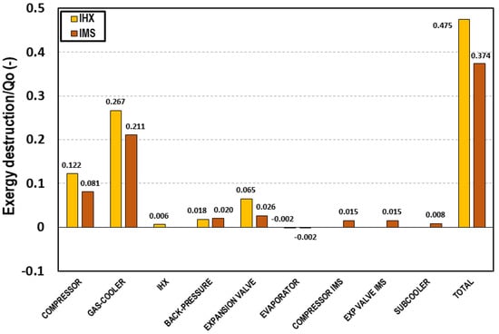
Figure 4.
Exergy destruction in each of the cycle components at tevap = 0 °C and tenv = 35 °C referred to the cooling capacity for the transcritical CO2 system with IHX (yellow) and with IMS (red).
4. Optimum Parameters
CO2 systems must be optimized in order to maximize the efficiency of the cycle. In the following section, the existence of these optimum parameters for which the COP is maximum is demonstrated for these cycles. The parameters that must be optimized are the discharge pressure and the subcooling degree.
COP of the system is the ratio between the cooling capacity on the main evaporator and the power consumption of both compressors as described in Equation (14).
where cooling capacity is:
Power consumption of the main compressor is calculated as Equation (16) and of the IMS compressor as Equation (17).
Combining Equations (5), (14)–(18) is obtained:
COP depends on , , and Equations (19)–(24) show the dependence of each of the previous mentioned parameters.
Thus, the COP is only function of the environment temperature, the evaporation level, the gas-cooler pressure, the subcooling degree, the efficiency of the gas-cooler and subcooler, the superheating in evaporator and on the subcooler, and the performance parameters of the compressors (Equation (26)). The last four parameters depend on the efficiency of the components of the plant (heat exchangers and compressors); evaporation and environment temperatures are fixed by the needs of the application and the ambient conditions. Gas-cooler pressure and the subcooling degree are the only parameters that can be modified in order to maximize COP, so these are the two parameters that must be optimized in CO2 cycles with integrated mechanical subcooling.
4.1. Optimum Pressure
All the transcritical CO2 systems must be optimized in terms of discharge pressure but for this system with integrated mechanical subcooling, the optimum pressure is not the same as for classical CO2 systems.
Figure 5 shows the COP variation for different ambient temperatures at different gas-cooler pressures. It can be observed that for all the cases, there exists a gas-cooler pressure for which the COP is maximum. It is also observed that for the ambient temperature of 25 °C, the optimum pressure corresponds to the critical one. This fact is due to the different temperature approach obtained between the ambient temperature and the gas-cooler exit temperature in subcritical and transcritical conditions. For this environment temperature, we found that reducing the pressure is beneficial for the system but when going under the critical pressure, the temperature approach increases significantly, worsening system performance.
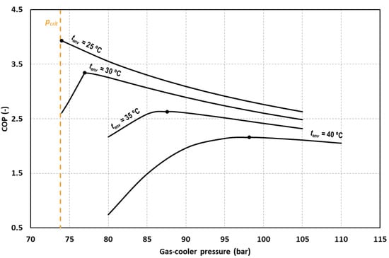
Figure 5.
Evolution of the COP as function of the gas-cooler pressure for tevap = 0 °C and different environment temperatures.
For the rest of the evaluated temperatures, working with a lower pressure than the optimum causes an important decrease in the COP value. For this reason, the system must be optimized in terms of gas-cooler pressure and the optimum working pressure must be determined.
Reducing or increasing the pressure with respect to the optimum, produces reductions in the value of the COP. For an environment temperature of 25 °C we obtain reductions of COP of 9% by increasing the optimum gas-cooler by 5 bars. A reduction of 3 bars and an increment of 3 bars produces reductions of 22.0% and 2.5% for tenv = 30 °C, respectively. The same variation produces reductions of 1.7% and 0.9% for tenv = 35 °C and of 0.9% and 0.3% for tenv = 40 °C. It must be said that if optimum conditions cannot be reached, it is advisable to work at pressures above the optimum since it is for lower pressures when the COP of the cycle drops dramatically.
The optimum pressure is determined for all the studied conditions and presented in Figure 6. It can be observed that the optimum pressure is clearly related to the environment temperature, but it is not dependent on the evaporation level.
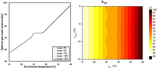
Figure 6.
Optimum discharge pressure depending on environment temperature and the evaporation level (left) and contour (right).
When working in subcritical conditions, the optimum pressure was established by condensation; in the transition zone, the optimum pressure corresponds to the critical pressure and for the transcritical regime, the optimum pressure increases linearly with the ambient temperature. The following correlations allow for determining the optimum gas-cooler pressure for CO2 systems with IMS.
The average error of the correlation (29) is 0.16 bars with a maximum error of 0.38 bars for a range of application from and .
One of the interests of these systems is that the subcooling cycle allows for reducing the high working pressure of the cycle. Figure 7 shows the optimum pressure reduction accomplished with the IMS system for transcritical CO2 systems compared to one of the classical correlations for transcritical CO2 systems [26]. Only the evaporations levels from −10 °C to 5 °C and gas-cooler outlet temperatures over 30 °C are compared according to the range of application of Liao’s correlation.
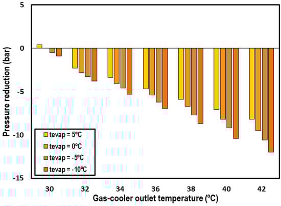
Figure 7.
Optimum pressure reduction obtained with the use of the IMS system.
An important reduction is observed, with it being more important when the outlet gas-cooler temperature is higher. The reductions reach values up to 12 bars for the highest gas-cooler outlet temperatures and lowest evaporation levels.
4.2. Optimum Subcooling Degree
The subcooling degree, presented in Equation (4), is an operation parameter that must be optimized both in transcritical and subcritical conditions. Figure 8 shows the evolution of the COP for different environment temperatures as a function of the subcooling degree, demonstrating that there is an optimum subcooling degree for each of the studied conditions.
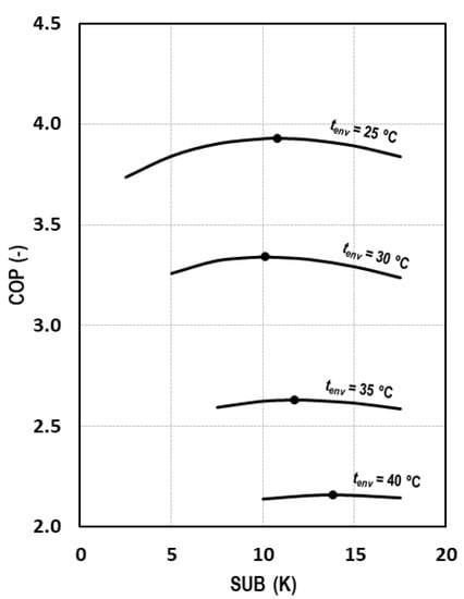
Figure 8.
Evolution of COP depending on the subcooling degree for tevap = 0 °C.
As it can be observed in Figure 8 and comparing these results with those of Figure 5, it can be stated that the influence of the subcooling on the COP is less strong than the pressure influence. For an environment temperature of 25 °C, we obtain reductions of COP of 0.6% and 0.7% by increasing or decreasing the optimum subcooling degree by 3 K. The same variation produces reductions of 0.6% and 0.4% for a decrease and increase of 2.5 K at tenv = 30 °C, of 1.4% and 0.9% for tenv = 35 °C, and of 0.9% and 0.6% for a decrease and increase of 4 K, respectively, at tenv = 40 °C.
When optimizing the subcooling degree, it can be observed that it is completely dependent on the environment temperature but also on the evaporation level, obtaining higher degrees for lower evaporation temperatures and higher ambient conditions. Figure 9 summarizes the optimum subcooling conditions for all the outdoor temperatures and evaporation levels.
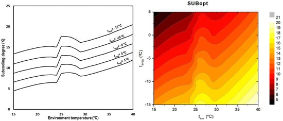
Figure 9.
Optimum subcooling degree depending on environment and evaporation temperatures (left) and contour (right).
The optimum subcooling degree increases as the environment temperature does. There is a change in the trend in the transition zone due to the changes in the thermal properties of the CO2 in the critical region [27] and the variation of the hypothesis between subcritical and transcritical regime.
Equation (30) describes the optimum subcooling degree as a function of the environment temperature and the evaporation temperature for transcritical CO2 systems with integrated mechanical subcooling.
The range of application of this correlation is for evaporating temperatures between −15.0 °C and 5.0 °C and environment temperatures from 15.0 °C to 40 °C with a maximum error of 1.6 K.
5. Energy Results
This section presents the main energy parameter results obtained from this study for the different evaluated conditions, always optimizing gas-cooler pressure and subcooling degree in order to obtain the maximum COP.
5.1. Cooling Capacity
Cooling capacity is calculated as the product of the mass flow circulating on the evaporator and the enthalpy difference between the inlet and outlet of the evaporator (Equation (15)). The inlet enthalpy is considered to be the same as the enthalpy at the exit of the subcooler.
Figure 10 shows the cooling capacity of the system for the range of studied environment temperatures and the different evaporation levels. The cooling capacity of the system is between 17.9 kW and 13.1 kW for tevap = 5 °C, between 15.6 kW and 11.3 kW for tevap = 0 °C, between 13.5 kW and 9.7 kW for tevap = −5 °C, between 11.5 kW and 8.2 kW for tevap = −10 °C, and between 9.7 kW and 6.9 kW for tevap = −15 °C. The observed trend is the same for all the evaporation levels, suffering a decrement on the capacity of the cycle as the environment temperature increases.
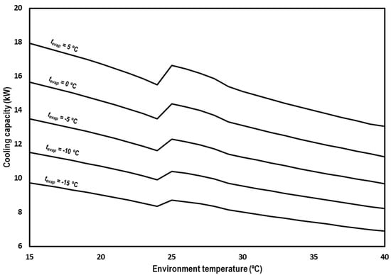
Figure 10.
Evolution of the cooling capacity for subcritical and transcritical conditions.
The enthalpy at the exit of the subcooler can be also defined as the enthalpy at the gas-cooler outlet; if it is less the enthalpy difference produced in the subcooler (Equation (31)), then the cooling capacity can be redefined as shown in Equation (31).
Expressed in another way, the cooling capacity is the sum of the cooling capacity of the cycle without subcooling plus the cooling capacity of the IMS system, as described in Equation (32).
Figure 11 represents the cooling capacity contribution of the IMS system as a percentage of the total cooling capacity. It can be noticed that the most important contributions of the IMS are obtained from 30 °C of ambient temperature. The contribution always increases as the environment temperature does, but the increments are more abrupt for these hottest levels; that is, for transcritical conditions. This increment in the contribution of the IMS is because it is in the transcritical regime where the CO2 pure system performs worse and thus needs more improvement. Analyzing the IMS contributions as a function of the evaporation level, higher contributions are obtained when the evaporation level is lower but the differences at different evaporation temperatures and a defined environment temperature are not so marked.
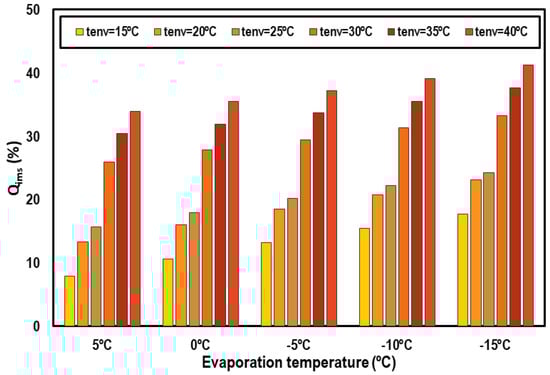
Figure 11.
Cooling capacity contribution of the IMS system.
5.2. COP
Figure 12 shows overall COP of the system for the optimum working conditions at the different evaluated evaporation levels and range of ambient temperatures. COP values decrease from 8.13 to 4.76 for tevap = 5 °C, from 6.17 to 3.94 for tevap = 0 °C, from 4.92 to 3.31 for tevap = −5 °C, from 4.03 to 2.79 for tevap = −10 °C, from 3.34 to 2.34 for tevap = −15 °C at subcritical conditions, and from 4.78 to 2.48 for tevap = 5 °C, from 3.93 to 2.16 for tevap = 0 °C, from 3.29 to 1.89 for tevap = −5 °C, from 2.79 to 1.66 for tevap = −10 °C, and from 2.38 to 1.45 for tevap = −15 °C in the transcritical regime.
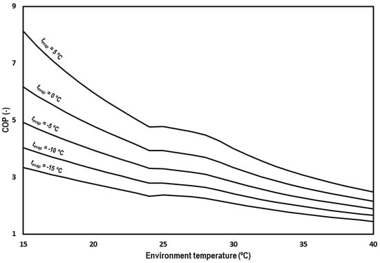
Figure 12.
Evolution of the COP for subcritical and transcritical conditions.
In order to contrast the possible advantages of the IMS solution, the theoretical results of Chen and Gu [28] for a single-stage CO2 transcritical system with an IHX have been contrasted with the COP values obtained in this work. The comparison is made for an environment temperature of 35 °C and evaporating levels from −10 to 5 °C. Figure 13 presents the COP values and the increments in relation to the system working with internal heat exchanger. On the left, the COP of both systems is presented for different evaporating temperatures, with the COP of the CO2 system with IMS always being higher. On the right, the increment of COP, achieved thanks to the IMS in reference to the system with IHX, is shown. It is observed that the increments are higher when lower the evaporation level is. The calculated increments are 15.9% for tevap = −10 °C, 14.8% for tevap = −5 °C, 12.9% for tevap = 0 °C, and 11.7% for tevap = 5 °C.
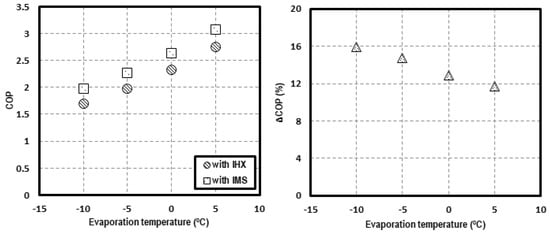
Figure 13.
COP comparison at tenv = 35 °C for a system with IHX and with IMS (left) and COP increments (right).
6. Conclusions
In this paper, the use of an integrated mechanical subcooling system for improving CO2 refrigeration systems is studied from a theoretical approach. The study has been carried out using a simplified thermodynamic model based on assumptions as close to reality as possible.
It has been demonstrated that the COP of CO2 refrigeration plants depend on the operating conditions, the performance of the components, and the discharge pressure and subcooling degree, with these last two being the only ones that can be adjusted to obtain the maximum COP in a specific plant for given operating conditions. Optimum working conditions of this type of cycle have been determined, with it being necessary to optimize the system in terms of discharge pressure but also the subcooling degree performed at the exit of the gas-cooler.
The optimum working conditions have been determined both for transcritical and subcritical conditions, for different evaporation levels (from −15.0 °C to +5 °C), and a wide range of ambient temperatures between 15.0 °C and 40.0 °C. It has been observed that the use of the IMS cycle reduces the optimum gas-cooler pressure of the system when working in a transcritical regime compared to classical pressure correlations of CO2 systems are higher. The optimum pressure is more reduced in ambient temperatures, reaching reductions over 10 bar for environment temperatures of 40 °C. At subcritical conditions, the optimum pressure corresponds to the condensation pressure. The optimum subcooling degree is also defined as being higher when the ambient temperature is higher and when the evaporation level is lower.
The main energy parameters of the cycle, COP and cooling capacity, are calculated for all the studied levels obtaining values of COP from 8.13 to 2.48 for tevap = 5 °C, from 6.17 to 2.16 for tevap = 0 °C, from 4.92 to 1.89 for tevap = −5 °C, from 4.03 to 1.66 for tevap = −10 °C, and from 3.34 to 1.45 for tevap = −15 °C. The system presents remarkable increases in COP compared to systems with internal heat exchanger, up to 15.9% for tevap = −10 °C and tenv = 35 °C. Cooling capacity of the system is between 17.9 kW and 13.1 kW for tevap = 5 °C, between 15.6 kW and 11.3kW for tevap = 0 °C, between 13.5 kW and 9.7 kW for tevap = −5 °C, between 11.5 kW and 8.2 kW for tevap = −10 °C, and between 9.7 kW and 6.9 kW for tevap = −15 °C.
Furthermore, the cycle has also been studied from a second law approach, identifying the components of the system, which present more irreversibilities. The exergy destruction in the expansion process is reduced and the components that present larger exergy destruction are gas-cooler and compressor.
Finally, as a general conclusion, we can affirm that the integrated mechanical subcooling cycle is an interesting subcooling method to improve the performance of CO2 plants and its high pressure and subcooling degree must be optimized in order to obtain the maximum COP.
Author Contributions
L.N.-A. and R.L. conceived the idea. L.N.-A. performed the theoretical simulations. R.L., D.C.-A., D.S. and R.C. checked the validity of the results. The manuscript was written by L.N.-A. and R.L., D.C.-A., D.S. and R.C. revised it. All authors have read and agreed to the published version of the manuscript.
Funding
This research was funded by Ministry of Science, Innovation and Universities-Spain (project RTI2018-093501-B-C21), the Ministry of Education, Culture and Sports-Spain (grant FPU16/00151) and the Jaume I University (project UJI-B2017-06).
Acknowledgments
The authors thank the Ministry of Science, Innovation and Universities-Spain (project RTI2018-093501-B-C21), the Ministry of Education, Culture and Sports-Spain (grant FPU16/00151) and the Jaume I University (project UJI-B2017-06) for financing this research work.
Conflicts of Interest
The authors declare that no part of manuscript has been published previously and that it will not be published elsewhere including electronically in the same form, in English or in any other languages without the written consent of the copyright-holder. Publication is approved by authors and by responsible authorities where the work was carried out. Authors declare that there is non additional conflict of interest.
Abbreviation
| Nomenclature | |
| app | approach, K |
| COP | coefficient of performance |
| h | specific enthalpy, kJ·kg−1 |
| mass flow kg·s−1 | |
| p | absolute pressure, bar |
| Pc | power consumption, kW |
| cooling capacity, kW | |
| SH | superheating, K |
| SUB | degree of subcooling produced in the subcooler, K |
| t | temperature, °C |
| Greek symbols | |
| density, kg·m−3 | |
| η | compressor efficiency |
| heat exchanger efficiency | |
| Subscripts | |
| dis | compressor discharge |
| evap | evaporation |
| exp | expansion |
| gc | gas-cooler |
| ims | corresponding to the IMS cycle |
| in | inlet |
| main | corresponding to the main cycle |
| 0 | death state |
| o | outlet |
| sub | corresponding to the subcooler |
| suc | compressor suction |
References
- European Commission. Regulation (EU) No 517/2014 of the European Parliament and of the Council of 16 April 2014 on Fluorinated Greenhouse Gases and Repealing Regulation (EC) No 842/2006. 2014. Available online: http://data.europa.eu/eli/reg/2014/517/oj (accessed on 16 December 2019).
- United Nations. The Kyoto Protocol to the Framework Convention on Climate Change. 1997. Available online: https://unfccc.int/resource/docs/convkp/kpeng.pdf (accessed on 16 December 2019).
- UNEP/TEAP. The Implications to the Montreal Protocol of the Inclusion of HFCs and PFCs in the Kyoto Protocol; USA, 1999. Available online: https://unep.ch/ozone/Assessment_Panels/TEAP/Reports/Other_Task_Force/HFCPFC.pdf (accessed on 16 December 2019).
- Sarkar, J.; Agrawal, N. Performance optimization of transcritical CO2 cycle with parallel compression economization. Int. J. Therm. Sci. 2010, 49, 838–843. [Google Scholar] [CrossRef]
- Chesi, A.; Esposito, F.; Ferrara, G.; Ferrari, L. Experimental analysis of R744 parallel compression cycle. Appl. Energy 2014, 135, 274–285. [Google Scholar] [CrossRef]
- Gullo, P.; Hafner, A.; Banasiak, K.; Minetto, S.; Kriezi, E.E. Multi-ejector concept: A comprehensive review on its latest technological developments. Energies 2019, 12, 406. [Google Scholar] [CrossRef]
- Lawrence, N.; Elbel, S. Experimental investigation on control methods and strategies for off-design operation of the transcritical R744 two-phase ejector cycle. Int. J. Refrig. 2019, 106, 570–582. [Google Scholar] [CrossRef]
- Llopis, R.; Nebot-Andrés, L.; Sánchez, D.; Catalán-Gil, J.; Cabello, R. Subcooling methods for CO2 refrigeration cycles: A review. Int. J. Refrig. 2018, 93, 85–107. [Google Scholar] [CrossRef]
- Llopis, R.; Cabello, R.; Sánchez, D.; Torrella, E. Energy improvements of CO2 transcritical refrigeration cycles using dedicated mechanical subcooling. Int. J. Refrig. 2015, 55, 129–141. [Google Scholar] [CrossRef]
- Llopis, R.; Sanz-Kock, C.; Cabello, R.; Sánchez, D.; Torrella, E. Experimental evaluation of an internal heat exchanger in a CO2 subcritical refrigeration cycle with gas-cooler. Appl. Therm. Eng. 2015, 80, 31–41. [Google Scholar] [CrossRef]
- Llopis, R.; Nebot-Andrés, L.; Cabello, R.; Sánchez, D.; Catalán-Gil, J. Experimental evaluation of a CO2 transcritical refrigeration plant with dedicated mechanical subcooling. Int. J. Refrig. 2016, 69, 361–368. [Google Scholar] [CrossRef]
- Sánchez, D.; Catalán-Gil, J.; Llopis, R.; Nebot-Andrés, L.; Cabello, R.; Torrella, E. Improvements in a CO2 transcritical plant working with two different subcooling systems. In Proceedings of the Refrigeration Science and Technology, Edinburgh, UK, 21–24 August 2016; pp. 1014–1022. [Google Scholar]
- Dai, B.; Liu, S.; Sun, Z.; Ma, Y. Thermodynamic Performance Analysis of CO2 Transcritical Refrigeration Cycle Assisted with Mechanical Subcooling. In Proceedings of the Energy Procedia: 8th International Conference on Applied Energy, Beijing, China, 8–11 October 2016; pp. 2033–2038. [Google Scholar]
- Dai, B.; Liu, S.; Li, H.; Sun, Z.; Song, M.; Yang, Q.; Ma, Y. Energetic performance of transcritical CO2 refrigeration cycles with mechanical subcooling using zeotropic mixture as refrigerant. Energy 2018, 150, 205–221. [Google Scholar] [CrossRef]
- Bush, J.; Beshr, M.; Aute, V.; Radermacher, R. Experimental evaluation of transcritical CO2 refrigeration with mechanical subcooling. Sci. Technol. Built Environ. 2017, 23, 1013–1025. [Google Scholar] [CrossRef]
- Beshr, M.; Bush, J.; Aute, V.; Radermacher, R. Steady state testing and modeling of a CO2 two-stage refrigeration system with mechanical subcooler. In Proceedings of the Refrigeration Science and Technology, Edinburgh, UK, 21–24 August 2016; pp. 893–900. [Google Scholar]
- Catalán-Gil, J.; Llopis, R.; Sánchez, D.; Nebot-Andrés, L.; Cabello, R. Energy analysis of dedicated and integrated mechanical subcooled CO2 boosters for supermarket applications. Int. J. Refrig. 2019, 101, 11–23. [Google Scholar] [CrossRef]
- Nebot-Andrés, L.; Llopis, R.; Sánchez, D.; Catalán-Gil, J.; Cabello, R. CO2 with mechanical subcooling vs. CO2 cascade cycles for medium temperature commercial refrigeration applications thermodynamic analysis. Appl. Sci. 2017, 7, 955. [Google Scholar] [CrossRef]
- Shapiro, D. Refrigeration System with Mechanical Subcooling. U.S. Patent 7,628,027, 8 December 2009. [Google Scholar]
- Cecchinato, L.; Chiarello, M.; Corradi, M.; Fornasieri, E.; Minetto, S.; Stringari, P.; Zilio, C. Thermodynamic analysis of different two-stage transcritical carbon dioxide cycles. Int. J. Refrig. 2009, 32, 1058–1067. [Google Scholar] [CrossRef]
- Qureshi, B.A.; Zubair, S.M. Mechanical sub-cooling vapor compression systems: Current status and future directions. Int. J. Refrig. 2013, 36, 2097–2110. [Google Scholar] [CrossRef]
- Nebot-Andrés, L.; Llopis, R.; Catalán-Gil, J.; Sánchez, D.; Calleja-Anta, D.; Cabello, R. Thermodynamics analysis of CO2 refrigeration cycles working with mechanical subcooling systems. In Proceedings of the 25th IIR International Congress of Refrigeration, Montreal, Canada, 24–30 August 2019. [Google Scholar]
- Lemmon, E.W.; Huber, M.L.; McLinden, M.O. REFPROP, NIST Standard Reference Database 23; National Institute of Standards: Gaithersburg, MD, USA, 2013; Volume 9.
- Gullo, P.; Hafner, A.; Banasiak, K. Transcritical R744 refrigeration systems for supermarket applications: Current status and future perspectives. Int. J. Refrig. 2018, 93, 269–310. [Google Scholar] [CrossRef]
- Purohit, N.; Sharma, V.; Sawalha, S.; Fricke, B.; Llopis, R.; Dasgupta, M.S. Integrated supermarket refrigeration for very high ambient temperature. Energy 2018, 165, 572–590. [Google Scholar] [CrossRef]
- Liao, S.M.; Zhao, T.S.; Jakobsen, A. A correlation of optimal heat rejection pressures in transcritical carbon dioxide cycles. Appl. Therm. Eng. 2000, 20, 831–841. [Google Scholar] [CrossRef]
- Torrella, E.; Sánchez, D.; Llopis, R.; Cabello, R. Energetic evaluation of an internal heat exchanger in a CO2 transcritical refrigeration plant using experimental data. Int. J. Refrig. 2011, 34, 40–49. [Google Scholar] [CrossRef]
- Chen, Y.; Gu, J. The optimum high pressure for CO2 transcritical refrigeration systems with internal heat exchangers. Int. J. Refrig. 2005, 28, 1238–1249. [Google Scholar] [CrossRef]


© 2019 by the authors. Licensee MDPI, Basel, Switzerland. This article is an open access article distributed under the terms and conditions of the Creative Commons Attribution (CC BY) license (http://creativecommons.org/licenses/by/4.0/).