Abstract
This manuscript presents an advanced exergo-economic analysis of a waste heat recovery system based on the organic Rankine cycle from the exhaust gases of an internal combustion engine. Different operating conditions were established in order to find the exergy destroyed values in the components and the desegregation of them, as well as the rate of fuel exergy, product exergy, and loss exergy. The component with the highest exergy destroyed values was heat exchanger 1, which is a shell and tube equipment with the highest mean temperature difference in the thermal cycle. However, the values of the fuel cost rate (47.85 USD/GJ) and the product cost rate (197.65 USD/GJ) revealed the organic fluid pump (pump 2) as the device with the main thermo-economic opportunity of improvement, with an exergo-economic factor greater than 91%. In addition, the component with the highest investment costs was the heat exchanger 1 with a value of 2.769 USD/h, which means advanced exergo-economic analysis is a powerful method to identify the correct allocation of the irreversibility and highest cost, and the real potential for improvement is not linked to the interaction between components but to the same component being studied.
1. Introduction
In thermodynamics systems, the irreversibility in the components of the system produce exergy destruction, and the continuous improvement of the performance of energy conversion systems based on exergy analysis has been a priority among researchers in this field of study [1], from energy analysis of the thermal systems [2] and trigeneration systems [3]. However, from all the information available with these traditional analyses, there is no relevant development on the analysis carried out with this methods to make further improvements to the components of a system [4], so advanced analyses and economic analysis are proposed to facilitate the thermal and economic improvement of the system.
In recent years, new concepts of exergy, such as endogenous/exogenous and avoidable/ unavoidable exergy destruction, have been employed to obtain relevant information for the identification of irreversibilities and thermodynamic inefficiencies in the systems [5]. In any thermodynamic system, the exergy destruction in the components can be generated in two ways. The first is due to the irreversibilities of the component under study, which is called endogenous exergy destruction, while the second is due to the irreversibilities of the other components that affect the component under study; this is called exogenous exergy destruction [6]. Thus, its optimization process will depend on the technical and economic limitations of the system, so there will only be a part of the exergy destruction and avoidable/unavoidable investment costs for each component. By uniting these two concepts, it is possible to identify improvements to the system [7].
Long et al. [8] evaluated the importance of the working fluid in the thermal performance of an organic Rankine cycle (ORC) by means of an external and internal exergetic analysis, and an optimization analysis based on a genetic algorithm with exergetic efficiency as an objective function. The results of the exergy analysis showed that the organic working fluid affects the exergetic efficiency of the cycle, with the opposite case in the internal part, where the efficiency did not present changes. The results of the optimization showed that the selection of the working fluid depends, to a greater degree, on the optimal evaporation temperature, which increases the exergetic efficiency of the cycle. Long et al. [9] performed an exergy analysis to evaluate the impacts of the evaporation pressure and ammonia fraction on the ammonia–water mixture of the system performance Kalina, obtaining that the evaporation pressure plays an important value in the internal and external exergetic efficiency. Additionally, optimal values are obtained from these in their ideal operation, as well as the ammonia fractions increasing the exergetic efficiency depending on the evaporation pressure. However, the exergetic efficiency of the cycle depends on the input temperature of the heat source, evaluating the impact of this parameter on internal and external exergetic efficiency.
Tian et al. [10] developed a techno-economic analysis of a system consisting of an ORC and an internal combustion engine operating with 235 kW diesel, in order to study the performance of 20 organic fluids. The results showed that the highest energy generated per unit of mass flow and the highest energy efficiency are obtained for refrigerant R-141b and refrigerant R-123, respectively. The study is limited to a single engine operating condition, and a traditional exergetic analysis where the real opportunities for both endogenous and exogenous component savings are not shown.
On the other hand, Zare V. [11], in order to find savings opportunities, added economic criteria to the thermal performance studies, applied to three configurations of an ORC. However, this application was limited to binary geothermal power plants, where the RORC presented better energy results, while from the economic point of view, the simple ORC was the best option because it is integrated by a smaller amount of equipment, which implies a lower acquisition cost. The results do not consider the evaluation of costs by components but of a global system. In addition, studies from the exergetic point of view have been developed in a traditional way, and thermal-economical studies for waste heat recovery systems of gas generation engines through ORC have not been widely integrated. Thus, the literature reports the results of the modeling developed by Kerme and Orfi [12], who studied the effect of the temperature of the organic fluid at the entrance of an ORC turbine on the energy and exergy performance, obtaining that the increase of the temperature increases the efficiency while total exergy destruction decreases it.
The combination of traditional and advanced exergetic analysis can provide significant thermodynamic information, such as the source and the amount of exergy destroyed by each component [13], and how much this destruction can be avoided [14], as in the case of solar energy collectors with a flat plate and a flat plate with a thin plate, resulting in the exergy destruction in the absorbent plate being greater than the rest of components, but according to the advanced exergetic analysis performed, this exergy destruction is endogenous and unavoidable, which means that the irreversibilities of this component are inherent in its operation mode [15].
Mohammadi et al. [16] studied a combination of conventional and advanced exergetic analyses in a supercritical CO2 recompression cycle to determine the potential for improving the thermal cycle performance, where the overall exergetic efficiency reached 17.13%, the system’s maximum best potential was 106.85 MW, and approximately 35% of exergy destruction could be avoided by focusing on components, such as the heat exchanger, turbine, and main compressor. These investigations can be complemented with the help of the combination of exergetic analysis [17] and economic analysis to obtain thermo-economic costs based on the irreversibilities of the components [18].
In addition, comparative studies have been carried out on different configurations of waste heat recovery cycles integrated to gas engines [18] and applications, such as Petrakopoulou et al. [19], where the first application of an exergo-economic analysis in a CO2 capture power plant was evaluated, revealing that the costs associated with exergy and investment analyses are endogenous for most components, where it proposed a suggestion for improving some components, such as the reactor, expander, and compressor. The literature review shows the case of a polygeneration plant operating in a geothermal cascade system coupled to an organic Rankine cycle that produces 40 kWe, where improvement potentials were found in the ORC cycle (10.61 kW) and heat exchanger (2.28 kW), while the exergo-economic analysis revealed an electricity production cost of 7.78 $/h and the advanced exergo-economic analysis suggests that the plant heat exchanger is the component with the greatest opportunity to reduce the exergy destruction of the heat exchanger equipment [20].
Another application was in a combined steam-organic Rankine cycle to recover waste heat from a gas turbine, where an exergo-economic analysis was performed using three different organic fluids (R124, R152a, and R34a), obtaining that the maximum exergy efficiency and the minimum rate of product costs are 57.62% and 396 $/h, respectively. In addition, the parametric study was complemented with genetic algorithm optimization, where it was obtained that the combined cycle with R152a has the best performance from the thermodynamic and exergo-economic point of view among the fluids analyzed [21].
Advanced exergetic analyses have focused on the ORC cycle, taking into account the advantage of adapting this cycle to another thermal system for different applications, such as waste heat recovery [22], thermodynamic optimization [23], and emergy analysis [24]. Also, several works have combined these studies to obtain improvement potentials. In applications in turbocharged combustion engines, conventional exergetic analysis gives the evaporator and the expander priority improvement potential while advanced exergy analysis suggests the expander and pump as a priority, and the cycle exergy destruction can be reduced by 36.5% [25]. For applications of advanced exergo-economic analysis taking into account waste heat recovery in geothermal applications, low-temperature solar applications, and waste heat recovery from engine gases, the exergetic efficiency of the ORC improves by 20%, optimizing the system through advanced exergetic analysis and proposing the expander, evaporator, condenser, and pump as improvement potentials. Different organic fluids have been tested in the ORCs to improve their performance, obtaining that pentane, cyclohexane, iso-butene, iso-pentane, and cyclohexane have the highest avoidable endogenous cost corresponding to the heat sources evaluated. In addition, the avoidable endogenous cost is sensitive to the heat source temperature, and it is possible to reduce the heat source temperature increase from 100 to 150 °C by 28% [26]. Therefore, it has been identified that advanced exergetic and thermo-economic analysis is one of the alternatives to achieve technically and economically favorable operating conditions, and to achieve its application in real conditions.
In response to the inadequate management of energy resources in industrial processes, there is a need to improve the efficiency of equipment and processes, in addition to reducing the environmental impact. Thus, the energy recovery of the exhaust line of the natural gas generation engines is one of the alternatives to increase the thermal efficiency of these systems [27]. However, this issue has been approached from different approaches but not articulated with alternative generation systems, which leads to an enormous scientific impact since if it is true that different ORC configurations have been studied, these have not been studied from an advanced exergetic point of view and integrated with thermo-economic modeling in real contexts of operation of stationary high-power natural gas turbocharged engines as a means of heat recovery, in order to obtain technically and economically viable solutions that allow their commercial application [28].
Thus, the main contribution of this work was to perform an advanced thermo-economic analysis of an organic Rankine cycle for a bottoming natural gas engine, and its respective comparison with the results obtained with conventional exergetic and exergo-economic analyses. The analysis of the irreversibilities of each component is presented, and the possible improvements to the cycle are found using the concepts of endogenous/exogenous and avoidable/unavoidable exergy destruction, combinined with the exergo-economic analysis, thus finding the advance cost rate improvement opportunities for each component based on the irreversibilities of the thermal system.
2. Methodology
2.1. Description of the Cycle
The cycle to be analyzed can be seen in Figure 1. The natural gas generation engine operates with an air/natural gas mixture, which is compressed before it enters the cylinders to improve the engine’s thermal performance. The exhaust gases are expanded by means of a turbo compressor flow S1 (708 K, 102 kPa), where energy is transferred by means of the heat exchanger 1 (HX1) to the thermal oil in stream S5, and discharged to the environment in stream S2. The thermal oil circulates through the energy supplied by the thermal oil pump (P1), and the hot fluid coming out of HX1 in stream S3 (616 K, 101.4 kPa) operates as a thermal source to evaporate and reheat through the heat exchanger 2 (HX2) the organic fluid, which is toluene in this case study. The maximum values of thee pressure and temperature of the organic Rankine cycle are presented in the turbine inlet (546 K, 675 kPa), where the organic fluid then expands into the S7 stream (475 K, 22 kPa) in the turbine (T1), generating additional energy without increasing the fuel consumption. To complete the thermal cycle, the organic fluid decreases the pressure to its lowest point, passing to the condensation stage from S7 to S8 (338 K, 675 kPa).
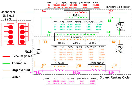
Figure 1.
The organic Rankine cycle waste heat recovery system.
The 2 MW Jenbacher engine JMS 612 GS-N. L was modeled and studied, as shown in Figure 2, with its technical specifications and nominal operating conditions [29]. This engine operates with natural gas as fuel, since its high robustness allows it to better adapt to variable load regimes. This engine is widely used for self-generation purposes worldwide and is installed in a company of the plastic sector in the city of Barranquilla, Colombia without any waste heat recovery system. The engine regulates fuel consumption to operate between a minimum load of 1000 kWe and a maximum load of 1982 kWe, with an excess air number (lambda) of 1.79 and 1.97, respectively, generating unused exhaust gases in each of its 12 cylinders with a temperature ranging from 580 to 650 °C.
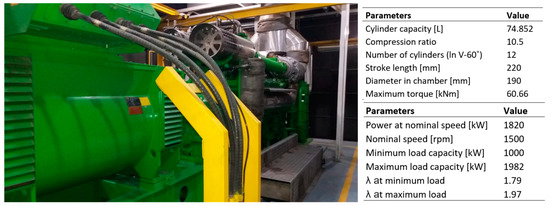
Figure 2.
Jenbacher JMS-612 GS-N.L technical specification.
2.2. Energy and Exergy Analyses
The exergy analysis is defined from the second law of thermodynamics, which means that, unlike the analysis of energy, it depends on the ambient temperature and pressure in which the process in study operates, which allows any system to be investigated in changing environmental conditions. The following assumptions were considered to develop thermodynamic modeling of the RORC:
- The thermal process and component subsystems were assumed as a steady state condition.
- All thermal devices were assumed in adiabatic conditions.
- The pressure drops in the waste heat recovery based on ORC devices and pipelines were neglected.
- The reference temperature for the physical and chemical exergy calculations was 288 K.
The global equation of exergy balance, valid for any volume control system, is shown in Equation (1) [21]:
where is the exergy of heat transfer in kW, is the mass flow in , is the specific entropy in , is the power in kW, and is the exergy destruction [30]. The exergy by heat transfer at temperature T is defined according to Equation (2) [31]:
The exergy of a fluid flow stream is defined as the energy power of the fluid flow, with the mass flow ratio of the fluid flow and the pressure and temperature of the fluid flow being necessary, as well as knowing the environmental conditions (pressure and temperature) in which the fluid flow operates [32]. Therefore, the exergetic power of the fluid flow stream was calculated according to Equation (3):
where the specific exergy () was calculated according to Equation (4) [33]:
Therefore, the exergy efficiency () for a thermal system was calculated according to Equation (5), as a function of the exergy output () and exergy input () to the system or device:
Some energy and exergy performance indicators were calculated for the waste heat recovery system based on the ORC [34], cycle thermal cycle efficiency , calculated according to Equation (6); the heat recovery efficiency as shown in Equation (7); and the overall energy conversion efficiency , given by Equation (8) [20]:
In addition, to measure the thermal efficiency improvement, the increase in thermal efficiency was calculated through Equation (9), as a function of the net power generated by the ORC (), and the heat supplied by the fuel mass rate ():
The specific fuel consumption (BSFC) was calculated by the mean of Equation (10) [20], and the absolute reduction in the specific fuel consumption as a consequence of the waste heat recovery was calculated as presented in Equation (11):
2.3. Advanced Exergetic Analysis
In advanced exergetic analysis, the values of exergy destruction are divided into four basic parts: Endogenous, exogenous, avoidable, and unavoidable exergy destruction. Avoidable and unavoidable exergy destruction refers to the system improvement potentials. The destruction of avoidable exergy, , represents the potential for improvement, during the destruction of unavoidable exergy, , which represents the limitations. The avoidable part of exergy destruction is described in Equation (12):
where the destruction of unavoidable exergy can be calculated with Equation (13):
The destruction of endogenous exergy, , and exogenous are related to the operational relation between the components of the system. The endogenous part of the exergy destruction is associated only with the irreversibilities that occur in component c, where all the other components operate ideally, and component c operates with its real conditions. On the other hand, the exogenous part of the exergy destruction is produced by the other components. This part can be determined by subtracting the endogenous exergy destruction from the real exergy destruction of component c, as shown in Equation (14):
In addition, the destruction of unavoidable endogenous exergy, , was calculated by the Equation (15), the destruction of unavoidable exogenous exergy, , through Equation (16), the destruction of avoidable endogenous exergy, , with Equation (17), and the destruction of avoidable exogenous exergy, , by mean of Equation (18) [7]:
2.4. Conventional Exergo-Economic Analysis
Exergetic analyses are used to determine the location, type, and magnitude of thermodynamic inefficiencies in system components. On the other hand, exergo-economic analyses combine the concept of exergy and economic analyses to obtain a tool for the optimization of energy systems [4]. In addition, the economic model takes into account the components’ cost, including amortization, maintenance, and fuel costs. To define a cost function that depends on interest optimization parameters, the cost of components must be expressed in terms of thermodynamic design parameters. The cost balance equations applied to component c of the system under study show that the sum of rates associated with all outgoing exergy flows equals the sum of cost rates of all incoming exergy flows, plus those corresponding to charges due to capital investment and operating and maintenance costs, as shown in Equation (19) [12]:
where the cost rates of input exergy flow () are defined in Equation (20), the cost rates of output exergy flow in Equation (21), the heat transfer cost rate in Equation (22), and the cost rate related to energy transfer by work in Equation (23) [35,36]:
where , , , and are the costs per unit of exergy in $/GJ, and is the sum of the cost rates associated with the cost of capital investment, , and operation and maintenance costs, , as shown in Equation (24) [37]:
where the is the purchase equipment cost of component c, which is given for all components of the system; N is the number of annual hours that the unit operates; and is the maintenance factor, which is generally approximately 1.06 [38]. The modeling and sizing of the plate heat exchanger equipment was done for each of the evaporator, condenser, and recovery zones [39]. In addition, thermoeconomic modeling and cost balances for the integrated configuration with the engine were developed by the authors [40]. Also, the CRF is the capital recovery factor, which depends on the interest rate and the estimated lifetime of the equipment, which was calculated based on Equation (25):
where is the interest rate, and n is the total period of operation of the system in years.
2.5. Advanced Exergo-Economic Análisis
2.5.1. Unavoidable and Avoidable Costs
The avoidable and unavoidable cost ratios associated with the exergy destruction within each component of the system were calculated by Equations (26) and (27), respectively:
where the sum of the avoidable and unavoidable costs of exergy destruction is equal to the total cost associated with exergy destruction, as shown in Equation (28) [5]:
The unavoidable investment cost was calculated considering an extremely inefficient version of component c [41]. Therefore, for the calculation of the unavoidable investment cost rate in the components [42], some operational conditions were proposed, as shown in Table 1.

Table 1.
Main assumptions for real conditions, ideal conditions, unavoidable exergy, and unavoidable investment cost.
The avoidable investment cost was calculated by subtracting the unavoidable cost rate from the total investment cost, as shown in Equation (29):
2.5.2. Endogenous and Exogenous Cost Rates
The endogenous cost rates and exogenous are defined according to Equations (30) and (31), respectively:
where the sums of the endogenous and exogenous cost rates of exergy destruction are equal to the total cost rate associated with exergy destruction, as defined in Equation (32):
Therefore, the exogenous investment rate was calculated with Equation (33) as follows:
2.5.3. Splitting Cost Rates
The cost rates with respect to exergy desegregation can be calculated with Equations (34)–(37) [6]:
where represents the unavoidable cost rate without component c, associated with the operation of the same component, and the value can be reduced by optimizing the component through technological improvements. Also, the cost is the avoidable exogenous cost rate that can be reduced by optimizing other components of the cycle while the costs and are the unavoidable endogenous and unavoidable exogenous cost rates, respectively.
The endogenous cost rate of component c can be calculated with Equation (38), and the rate of unavoidable endogenous investment costs can be calculated using Equation (39) [7]:
Therefore, the equations used to calculate the desegregated investment costs are presented from Equations (40) to (42):
3. Results and Discussion
In this section, the influence of the engine load on the heat recovery system energy and exergy performance integrated into the natural gas engine was studied, as an alterntive to reduce the global operational cost and increase the thermal efficiency [43]. The engine power control system adjusts internal engine variables, such as the pressure and temperature of the air-fuel mixture before entering the cylinders, and the recirculation percentage, to provide high efficiency in partial load operation of the gas engine. Some energy indicators were proposed to study the performance of the waste heat recovery system based on ORC, as shown in Figure 3, while the evaporating pressure was set to 675.8 kPa, and toluene was selected as the working fluid [33]. For safety restriction, all feasible operating points of the proposed system at different engine loads ensured that toluene evaporates completely at the outlet of the evaporator to prevent corrosion of the liquid in the expander, in addition to a gas temperature at the outlet of the evaporator (state 11) being higher than the acid dew temperature (200 °C) to avoid acidic corrosion of the exhaust [34].
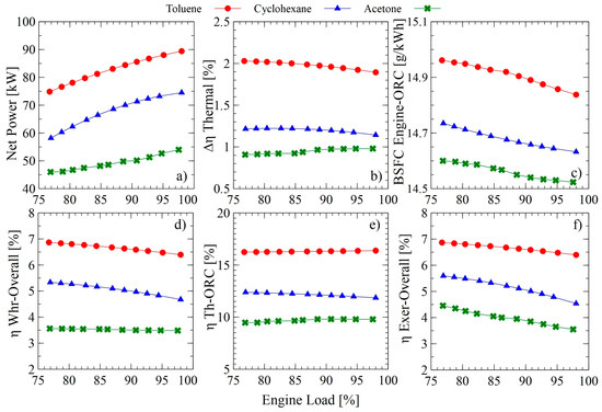
Figure 3.
Energy and exergy indicator of the waste heat recovery system with different organic fluids and engine load, (a) met power, (b) Absolute increase in thermal efficiency, (c) specific fuel consumption, (d) global energy conversion efficiency, (e) ORC thermal efficiency, and (f) global exergetic efficiency.
The results show that the absolute increase in thermal efficiency (Figure 3b) decreases for toluene and cyclohexane, as does the overall energy conversion efficiency (Figure 3d) with an increasing engine load, while the net power output (Figure 3a) presents its maximum value with toluene (89.4 kW—97.9%), cyclohexane (73.2 kW—97.9%), and acetone (53.2 kW—91.81%), respectively. However, in an engine operating interval, acetone presents a slight increase in thermal efficiency, and then decreases, presenting a maximum at an 82.68% engine load.
These results are due to a higher engine load, implying an increase in the exhaust gas flow according to the first and second laws of thermodynamics [44] while a greater energy loss is presented in the recuperator heat exchanger 1 (HX1) because of the evaporation pressure and thermal oil temperature have been limited. As the engine load increases, there is an increase in the fluid evaporating temperature at the evaporator. Therefore, the power increases, which is the main factor for thermal and exergetic efficiency. However, the isentropic turbine efficiency decreases slightly as a consequence of the increase in the thermal oil temperature, causing a decrease in the energy indicators at high engine loads. Likewise, the tendency to increase the power with the engine load is a consequence of both the increase in the inlet thermal oil temperature to the evaporator, which leads to an increase in the toluene mass flow, and the enthalpy difference between the outlet and the inlet of the pump and turbine, but this is more relevant in the turbine.
In addition, the results obtained from the traditional exergetic and exergo-economic analysis are shown in Table 2, where the exergy and fraction of exergy destroyed, , shows that the greatest values are present in the heat exchanger 1 (shell and tube heat exchanger) with 32.54%, the evaporator (28.32%), and the condenser with 27.97%. The component with the highest destroyed exergy value (41.95 kW) is heat exchanger 1, being one of the components with the lowest exergetic efficiency of the cycle, due to the large heat exchanger area required and the high temperature difference. The greater the investment and the cost of exergy destroyed, the greater the influence of the component in the system, therefore, the component with the greatest improvement in cost efficiency of the total plant can be defined. In the case study, the components with the greatest opportunities for improvement in this ratio are the condenser and HX 1. Therefore, these components are the most important from a thermodynamic point of view.
Table 2.
The results of conventional analysis for all components in the waste heat recovery system.
The exergo-economic factor, , is the effective parameter that allows us to compare and evaluate the components that make up the system. A high value for this parameter indicates that for the component under study, acquisition costs predominate over operation and maintenance costs. For example, in the case of the condenser, which is the component with the lowest value of the exergo-economic factor, it can be concluded that expenses are mostly related to operating and maintenance costs compared to acquisition costs.
By means of the advanced exergetic analysis, the exergy destruction can be disaggregated for each one of the components. In this way, the real possibilities of improvement can be determined both through the operational and design point of view of the component, and the global consideration of the thermal system. From the solution of Equations (12)–(18), and the unavoidable operation conditions described in Table 1, the disaggregation of the exergy can be found in its endogenous, exogenous, avoidable, and unavoidable part, as well as avoidable and unavoidable endogenous and its avoidable and unavoidable exogenous counterpart. The determination of the avoidable part of the destroyed exergy is a significant step because it allows identification of opportunities for improvement in the component and its interaction with the rest of the components. Also, this result allows knowledge of which is the optimal way to increase the thermal efficiency of the system, besides providing valuable information about how the components operate together as a global system. Figure 4 presents a graphical version of the improvement opportunities in each component from the exergetic point.
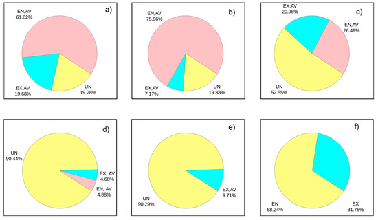
Figure 4.
Advanced exergy analyses for each component in the ORC cycle, (a) HX 1, (b) P1, (c) turbine, (d) P2, (e) evaporator, and (f) condenser.
The results of the advanced exergetic analysis and economic exergetic analysis are presented in Table 3, where the disaggregation of the destroyed exergy was calculated as a function of the endogenous, exogenous, avoidable, and unavoidable for each of the components under study. The results show that most of the destroyed exergy is endogenous (78.53% of the total destroyed exergy), emphasizing that the interaction between components does not have a significant effect on the overall exergetic performance of the cycle. Similarly, it is noted that the component with the greatest avoidable exergy destroyed in the system is the turbine, with a value of 11.075 kW, where 69.625% is endogenous and 30.374 is exogenous, which means that in the turbine, there is a real great opportunity for improvement. On the other hand, in the unavoidable part, the components with the greatest technological limitations are the HX 1 and evaporator, representing 96.1% of the total unavoidable exergy of the cycle.
Table 3.
Splitting exergy destruction for each component.
The equations presented in Section 2.5.2 and Section 2.5.3 were used to calculate the advance exergy destruction costs as shown in Table 4, which is based on the result of the advanced destroyed exergy.
Table 4.
Advanced exergy destruction cost rates for all components in the waste heat recovery system.
It can be observed that the endogenous exergy destruction is higher than the exogenous cost in the components of the thermal cycle, which is a consequence of the high endogenous investment costs values for all components of the system with respect to the exogenous investment cost, as shown in Table 5. Therefore, it can be established that the interaction between components in terms of investment costs is not very relevant in the system; however, for the component under study, it is a parameter of vital importance. Also, it can be observed that the rates of unavoidable investment costs for the components studied showed an inclination in the unavoidable part.
Table 5.
Advanced investment costs for all components in the WHR (Wast Heat Recovery).
Negative values of exogenous investment cost rates (ZEX, ZAV,EX, ZUN,EX) revealed that investment costs within these components might decrease if investment costs within the other components are increased.
In order to show a comparison of the destroyed exergy relationship between traditional and advanced exergetic analysis, Figure 5 is shown. In Figure 5A, a slight difference of the parameter under study is denoted because the one that was calculated by means of the advanced exergetic analysis only emphasizes the exergy that is destroyed by each component, that is to say, the endogenous part (without the interaction that this one has with its surroundings).
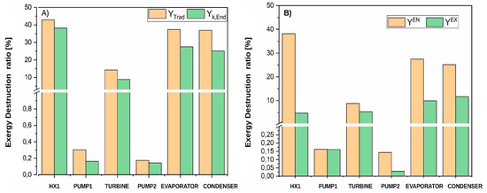
Figure 5.
Contribution of each component to the overall exergy destruction of the cycle based on (A) traditional and (B) advanced exergy analysis.
However, the relationship of exergy destroyed by the component was also calculated by emphasizing which fraction is borne by the component itself or by the interaction of the component with its surroundings, as shown in Figure 5B. From this graph, what has been mentioned before is supported, that is, that the interaction between each of the components of the system is not significant in comparison to the exergy that destroys the component under its own operating conditions. A comparative analysis was performed by implementing a new exergo-economic factor calculated by advanced exergetic analysis, as shown in Figure 6.
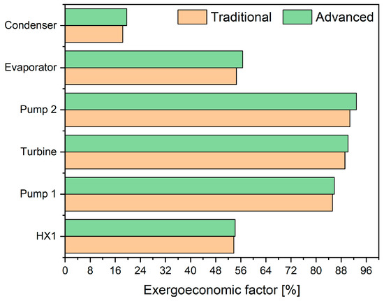
Figure 6.
Comparison of the calculated exergo-economic factor based on traditional and advanced exergy analysis.
As a percentage, it can be seen that the exergo-economic factor, as well as the traditional and advanced approach, presents a similarity in the components that make up the system. So, the main efforts should concentrate on designing the most efficient heat exchangers [35], with a smaller heat transfer area and less exergy destruction, without increasing the purchase equipment costs.
4. Conclusions
In this paper, the benefit offered by developed traditional and advanced exergetic analysis in thermal systems was shown, in particular in the organic Rankine cycle systems. Exergetic analysis allows determination of the sources of irreversibility in a thermal system, and therefore indicates the starting points of an optimization procedure, and contributes to the rational use of the energetic resources. In the study carried out, it was possible to determine which equipment that resulted in greater destruction of exergy introduced in the waste heat recovery system based on the organic Rankine cycle. The equipment in which the design or operational improvements can be made was also determined, since the implementation of some recommendations is not practical for optimizing the cycle due to operational or design limitations. Therefore, traditional exergy, advanced exergy, and exergo-economic analysis were applied to gain a better understanding of the system performance. Moreover, a comprehensive comparison was conducted to further assess the system from various points of view.
The conventional exergy showed that the heat exchanger 1 had the largest exergy destruction and exergy destruction, and highest investment costs (41.95 kW, 32.54%, and 2.67 USD/h). The results of the energetic and exergetic analysis of the system showed that the exergy destroyed is a measure of the degree of process irreversibility. Thus, in the case of heat exchanger 1, the causes of the irreversibility were due to the heat transfer through a finite temperature difference higher than 100 °C. Similarly, the results of exergy destructions appeared to be in accordance with the exergy efficiencies. That is, a smaller exergy efficiency implies greater exergy destruction in the system components.
Also, the highest exergo-economic factor was found in the pump 2, turbine, and pump 1, with 90.78%, 89.20%, and 85.24%, respectively. These results were a consequence of the high effect of the purchased equipment cost, and the low thermodynamic efficiency in the aforementioned devices, where the probable solution could be the implementation of low-cost components, which are usually characterized by a lower energy efficiency.
Most of the exergy destruction calculated was endogenous (78.53%), emphasizing that the interaction between components does not have a significant effect on the overall exergetic performance of the cycle. The maximum unavoidable exergy was found for the heat exchanger 1, with 90.44%. This indicates that there are not too many ways to improve this component. Nevertheless, other components, such as pump 2, pump 1, and turbine 1, have the minimum unavoidable exergy destruction, with 0.028, 0.03, and 2.819 kW. In addition, the component with the highest cost rate was the condenser with 7.188 USD/h, followed by the heat exchanger 1 with 2.3 USD/h, but the highest avoidable cost rate was found for the turbine with a value of 0.701 USD/h.
On the other hand, the advanced exergo-economic analyses showed that the turbine is the component with the major purchase equipment cost in the system, with a value of 7.898 USD/h, which is 54.09% of the total equipment cost of the system. For all components studied, the endogenous investment cost was higher than the exogenous part, showing the weak relation between them. A comparison was realized between the traditional and advanced exergo-economic factor, which resulted in a similar effect in each component, but the advanced exergy approach presented a slightly higher value, implying that the advanced exergetic analysis gives greater precision in terms of results without ignoring the really great opportunities for improvement.
Author Contributions
Conceptualization: G.V.O.; Methodology: G.V.O. and J.D.F.; Software: G.V.O., J.P.R. and J.D.F.; Validation: G.V.O., J.P.R. and J.D.F.; Formal Analysis: G.V.O., J.P.R. and J.D.F.; Investigation: G.V.O.; Resources: G.V.O.; Writing—Original Draft Preparation: G.V.O. and J.P.R.; Writing—Review and Editing: G.V.O. and J.D.F.; Funding Acquisition: G.V.O. All authors have read and agreed to the published version of the manuscript.
Funding
This research received no external funding.
Acknowledgments
Acknowledgments to Universidad del Atlántico, Universidad Francisco de Paula Santander, and the E2 Energía Eficiente S.A E.S. P company by the support received to conduct this research.
Conflicts of Interest
The authors declare no conflict of interest.
Abbreviations
The following abbreviations are used in this manuscript:
| ICE | Internal Combustion Engine |
| HX 1 | Heat Exchanger 1 |
| HX2 | Heat Exchanger 2 |
| ORC | Organic Rankine Cycle |
| PP | Pinch Point |
| WHR | Waste heat recovery |
| CRF | Capital Recovery Factor |
| Equipment Purchase Cost of component C | |
| Nomenclature | |
| E | Exergy |
| h | Enthalpy |
| Fuel mass rate | |
| P | Pressure |
| Q | Heat |
| s | Entropy |
| Rp | Pressure ratio |
| T | Temperature |
| W | Power |
| Exergy efficiency | |
| η | Energy efficiency |
| Exergy destruction ratio | |
| Investment costs | |
| Endogenous exergy destruction cost rates | |
| Exogenous exergy destruction cost rates | |
| N | Number of annual operation hours |
| Subscripts | |
| 0 | References condition |
| Cond | Condenser |
| ch | Chemical |
| D | Destruction |
| Evap | Evaporator |
| F | Fuel |
| iso | Isoentropic |
| k | Component |
| min | Minimum |
| P | Product |
| ph | Physical |
| Pump | Pump |
| Th | Theorical |
| Tot | Total |
| Turb | Turbine |
| Superscripts | |
| AV | Avoidable |
| EN | Endogenous |
| EX | Exogenous |
| EN, AV | Endogenous avoidable |
| EN, UN | Endogenous unavoidable |
| EX, AV | Exogenous avoidable |
| EX, UN | Exogenous unavoidable |
| id | Ideal |
| RS | Real |
| UN | Unavoidable |
References
- Petrakopoulou, F.; Tsatsaronis, G.; Morosuk, T.; Carassai, A. Conventional and advanced exergetic analyses applied to a combined cycle power plant. Energy 2012, 41, 146–152. [Google Scholar] [CrossRef]
- Morosuk, T.; Tsatsaronis, G. Advanced exergy-based methods used to understand and improve energy-conversion systems. Energy 2019, 169, 238–246. [Google Scholar] [CrossRef]
- Anvari, S.; Khoshbakhti Saray, R.; Bahlouli, K. Conventional and advanced exergetic and exergoeconomic analyses applied to a tri-generation cycle for heat, cold and power production. Energy 2015, 91, 925–939. [Google Scholar] [CrossRef]
- Tsatsaronis, G. Strengths and Limitations of Exergy Analysis BT-Thermodynamic Optimization of Complex Energy Systems; Bejan, A., Mamut, E., Eds.; Springer: Dordrecht, The Netherlands, 1999; pp. 93–100. ISBN 978-94-011-4685-2. [Google Scholar]
- Tsatsaronis, G.; Park, M.-H. On avoidable and unavoidable exergy destructions and investment costs in thermal systems. Energy Convers. Manag. 2002, 43, 1259–1270. [Google Scholar] [CrossRef]
- Kelly, S. Energy Systems Improvement based on Endogenous and Exogenous Exergy Destruction. Ph.D. Thesis, Technische Universität Berlin, Berlin, Germany, 2008. [Google Scholar]
- Petrakopoulou, F. Comparative Evaluation of Power Plants with CO2 Capture: Thermodynamic, Economic and Environmental Performance. Ph.D. Thesis, Technische Universität Berlin, Berlin, Germany, 2010. [Google Scholar]
- Long, R.; Bao, Y.J.; Huang, X.M.; Liu, W. Exergy analysis and working fluid selection of organic Rankine cycle for low grade waste heat recovery. Energy 2014, 73, 475–483. [Google Scholar] [CrossRef]
- Long, R.; Kuang, Z.; Li, B.; Liu, Z.; Liu, W. Exergy analysis and performance optimization of Kalina cycle system 11 (KCS-11) for low grade waste heat recovery. Energy Procedia 2019, 158, 1354–1359. [Google Scholar] [CrossRef]
- Tian, H.; Shu, G.; Wei, H.; Liang, X.; Liu, L. Fluids and parameters optimization for the organic Rankine cycles (ORCs) used in exhaust heat recovery of Internal Combustion Engine (ICE). Energy 2012, 47, 125–136. [Google Scholar] [CrossRef]
- Zare, V. A comparative exergoeconomic analysis of different ORC configurations for binary geothermal power plants. Energy Convers. Manag. 2015, 105, 127–138. [Google Scholar] [CrossRef]
- Kerme, E.D.; Orfi, J. Exergy-based thermodynamic analysis of solar driven organic Rankine cycle. J. Therm. Eng. 2015, 1, 192–202. [Google Scholar] [CrossRef]
- Boyano, A.; Morosuk, T.; Blanco-Marigorta, A.M.; Tsatsaronis, G. Conventional and advanced exergoenvironmental analysis of a steam methane reforming reactor for hydrogen production. J. Clean. Prod. 2012, 20, 152–160. [Google Scholar] [CrossRef]
- Morozyuk, T.; Tsatsaronis, G. Strengths and Limitations of Advanced Exergetic Analyses. In Proceedings of the ASME International Mechanical Engineering Congress and Exposition, San Diego, CA, USA, 15–21 November 2013; Volume 6. [Google Scholar]
- Mortazavi, A.; Ameri, M. Conventional and advanced exergy analysis of solar flat plate air collectors. Energy 2018, 142, 277–288. [Google Scholar] [CrossRef]
- Mohammadi, Z.; Fallah, M.; Mahmoudi, S.M.S. Advanced exergy analysis of recompression supercritical CO2 cycle. Energy 2019, 178, 631–643. [Google Scholar] [CrossRef]
- Yue, T.; Lior, N. Exergo-economic competitiveness criteria for hybrid power cycles using multiple heat sources of different temperatures. Energy 2017, 135, 943–961. [Google Scholar] [CrossRef]
- Marami Milani, S.; Khoshbakhti Saray, R.; Najafi, M. Exergo-economic analysis of different power-cycle configurations driven by heat recovery of a gas engine. Energy Convers. Manag. 2019, 186, 103–119. [Google Scholar] [CrossRef]
- Petrakopoulou, F.; Tsatsaronis, G.; Morosuk, T. Advanced Exergoeconomic Analysis of a Power Plant with CO2 Capture. Energy Procedia 2015, 75, 2253–2260. [Google Scholar] [CrossRef]
- Ambriz-Díaz, V.M.; Rubio-Maya, C.; Ruiz-Casanova, E.; Martínez-Patiño, J.; Pastor-Martínez, E. Advanced exergy and exergoeconomic analysis for a polygeneration plant operating in geothermal cascade. Energy Convers. Manag. 2019, 112227. [Google Scholar] [CrossRef]
- Nazari, N.; Heidarnejad, P.; Porkhial, S. Multi-objective optimization of a combined steam-organic Rankine cycle based on exergy and exergo-economic analysis for waste heat recovery application. Energy Convers. Manag. 2016, 127, 366–379. [Google Scholar] [CrossRef]
- Mikielewicz, D.; Wajs, J.; Ziółkowski, P.; Mikielewicz, J. Utilisation of waste heat from the power plant by use of the ORC aided with bleed steam and extra source of heat. Energy 2016, 97, 11–19. [Google Scholar] [CrossRef]
- Scaccabarozzi, R.; Tavano, M.; Invernizzi, C.M.; Martelli, E. Thermodynamic Optimization of heat recovery ORCs for heavy duty Internal Combustion Engine: Pure fluids vs. zeotropic mixtures. Energy Procedia 2017, 129, 168–175. [Google Scholar] [CrossRef]
- Zhang, H.; Guan, X.; Ding, Y.; Liu, C. Emergy analysis of Organic Rankine Cycle (ORC) for waste heat power generation. J. Clean. Prod. 2018, 183, 1207–1215. [Google Scholar] [CrossRef]
- Galindo, J.; Ruiz, S.; Dolz, V.; Royo-Pascual, L. Advanced exergy analysis for a bottoming organic rankine cycle coupled to an internal combustion engine. Energy Convers. Manag. 2016, 126, 217–227. [Google Scholar] [CrossRef]
- Dai, B.; Zhu, K.; Wang, Y.; Sun, Z.; Liu, Z. Evaluation of organic Rankine cycle by using hydrocarbons as working fluids: Advanced exergy and advanced exergoeconomic analyses. Energy Convers. Manag. 2019, 197, 111876. [Google Scholar] [CrossRef]
- Valencia, G.; Acevedo, C.; Duarte, J. Thermoeconomic optimization with PSO algotithm of waste heat recovery system based on Organic Rankine Cycle system for a natural engine. Energies 2019, 12, 4165. [Google Scholar] [CrossRef]
- Ochoa, G.V.; Peñaloza, C.A.; Rojas, J.P. Thermoeconomic modelling and parametric study of a simple orc for the recovery ofwaste heat in a 2 MW gas engine under differentworking fluids. Appl. Sci. 2019, 9, 4526. [Google Scholar] [CrossRef]
- Ochoa, G.V.; Isaza-Roldan, C.; Forero, J.D. A phenomenological base semi-physical thermodynamic model for the cylinder and exhaust manifold of a natural gas 2-megawatt four-stroke internal combustion engine. Heliyon 2019, 5, e02700. [Google Scholar] [CrossRef] [PubMed]
- Regulagadda, P.; Dincer, I.; Naterer, G.F. Exergy analysis of a thermal power plant with measured boiler and turbine losses. Appl. Therm. Eng. 2010, 30, 970–976. [Google Scholar] [CrossRef]
- Ahmadi, G.; Toghraie, D.; Azimian, A.; Akbari, O.A. Evaluation of synchronous execution of full repowering and solar assisting in a 200MW steam power plant, a case study. Appl. Therm. Eng. 2017, 112, 111–123. [Google Scholar] [CrossRef]
- Taner, T.; Sivrioglu, M. Energy–exergy analysis and optimisation of a model sugar factory in Turkey. Energy 2015, 93, 641–654. [Google Scholar] [CrossRef]
- Ahmadi, G.; Toghraie, D.; Akbari, O.A. Solar parallel feed water heating repowering of a steam power plant: A case study in Iran. Renew. Sustain. Energy Rev. 2017, 77, 474–485. [Google Scholar] [CrossRef]
- Valencia, G.; Fontalvo, A.; Cárdenas, Y.; Duarte, J.; Isaza, C. Energy and exergy analysis of different exhaust waste heat recovery systems for natural gas engine based on ORC. Energies 2019, 12, 2378. [Google Scholar] [CrossRef]
- Quoilin, S.; Aumann, R.; Grill, A.; Schuster, A.; Lemort, V.; Spliethoff, H. Dynamic modeling and optimal control strategy of waste heat recovery Organic Rankine Cycles. Appl. Energy 2011, 88, 2183–2190. [Google Scholar] [CrossRef]
- Sayyaadi, H. Multi-objective approach in thermoenvironomic optimization of a benchmark cogeneration system. Appl. Energy 2009, 86, 867–879. [Google Scholar] [CrossRef]
- Ghaebi, H.; Amidpour, M.; Karimkashi, S.; Rezayan, O. Energy, exergy and thermoeconomic analysis of a combined cooling, heating and power (CCHP) system with gas turbine prime mover. Int. J. Energy Res. 2011, 35, 697–709. [Google Scholar] [CrossRef]
- Bejan, A.; Tsatsaronis, G.; Moran, M.J. Thermal Design & Optimization; John Wiley & Sons: Hoboken, NJ, USA, 1995; ISBN 0-471-58467-3. [Google Scholar]
- Valencia, G.; Núñez, J.; Duarte, J. Multiobjective optimization of a plate heat exchanger in a waste heat recovery organic rankine cycle system for natural gas engines. Entropy 2019, 21, 655. [Google Scholar] [CrossRef]
- Valencia, G.; Duarte, J.; Isaza-Roldan, C. Thermoeconomic analysis of different exhaust waste-heat recovery systems for natural gas engine based on ORC. Appl. Sci. 2019, 9, 4017. [Google Scholar] [CrossRef]
- Morosuk, T.; Tsatsaronis, G. Advanced Exergoeconomic Analysis of a Refrigeration Machine: Part 1—Methodology and First Evaluation. In Proceedings of the ASME 2011 International Mechanical Engineering Congress and Exposition, Denver, CO, USA, 11–17 November 2011; pp. 47–56. [Google Scholar]
- Morosuk, T.; Tsatsaronis, G. Advanced Exergoeconomic Analysis of a Refrigeration Machine: Part 2—Improvement. In Proceedings of the ASME 2011 International Mechanical Engineering Congress and Exposition, Denver, CO, USA, 11–17 November 2011; pp. 57–65. [Google Scholar]
- Budes, F.B.; Ochoa, G.V.; Escorcia, Y.C. Hybrid PV and Wind grid-connected renewable energy system to reduce the gas emission and operation cost. Contemp. Eng. Sci. 2017, 10, 1269–1278. [Google Scholar] [CrossRef][Green Version]
- Diaz, G.A.; Forero, J.D.; Garcia, J.; Rincon, A.; Fontalvo, A.; Bula, A.; Padilla, R.V. Maximum power from fluid flow by applying the first and second laws of thermodynamics. J. Energy Resour. Technol. 2017, 139, 032903. [Google Scholar] [CrossRef]


© 2020 by the authors. Licensee MDPI, Basel, Switzerland. This article is an open access article distributed under the terms and conditions of the Creative Commons Attribution (CC BY) license (http://creativecommons.org/licenses/by/4.0/).