Article

Thermo-Economic Assessment of a Gas Microturbine-Absorption Chiller Trigeneration System under Different Compressor Inlet Air Temperatures

by
Guillermo Valencia Ochoa
1,*,
Carlos Acevedo Peñaloza
2 and
Jorge Duarte Forero
1
1
Programa de Ingeniería Mecánica, Universidad del Atlántico, Carrera 30 Número 8-49, Puerto Colombia, Barranquilla 080007, Colombia
2
Facultad de Ingeniería, Universidad Francisco de Paula Santander, Avenida Gran Colombia No. 12E-96, Cúcuta 540003, Colombia
*
Author to whom correspondence should be addressed.
Energies 2019, 12(24), 4643; https://doi.org/10.3390/en12244643
Submission received: 5 November 2019 / Revised: 29 November 2019 / Accepted: 3 December 2019 / Published: 6 December 2019
(This article belongs to the Special Issue Thermal Systems)

Abstract

:
This manuscript presents a thermo-economic analysis for a trigeneration system integrated by an absorption refrigeration chiller, a gas microturbine, and the heat recovery steam generation subsystem. The effect of the compressor inlet air temperature on the thermo-economic performance of the trigeneration system was studied and analyzed in detail based on a validated model. Then, we determined the critical operating conditions for which the trigeneration system presents the greatest exergy destruction, producing an increase in the costs associated with loss of exergy, relative costs, and operation and maintenance costs. The results also show that the combustion chamber of the gas microturbine is the component with the greatest exergy destruction (29.24%), followed by the generator of the absorption refrigeration chiller (26.25%). In addition, the compressor inlet air temperature increases from 305.15 K to 315.15 K, causing a decrease in the relative cost difference of the evaporator (21.63%). Likewise, the exergo-economic factor in the heat exchanger and generator presented an increase of 6.53% and 2.84%, respectively.

1. Introduction

The increase in global warming, adding to the scarcity of fossil fuels, has motivated the development of new technologies to improve the efficiency of existing processes in power plants [1,2]. Among the available options, multi-generation processes such as the trigeneration cycle have been widely used as they allow for greater efficiency, lower costs, and reduced emissions [3]. Therefore, researchers have been working to increase the potential of this type of energy generation process through heat recovery under the steam generator, organic Rankine cycles [3], and absorption chillers [4,5].
Absorption chiller cooling technology is increasingly used because it utilizes refrigerants and absorbents that do not have a negative effect on the environment. In addition, it is possible to feed this type of device with waste heat or some other renewable energy source such as solar energy [6]. Therefore, they are systems widely used in the industrial sector because of the lower energy cost production and potential gas emission reduction [7].
Several studies have developed relevant contributions to the thermo-economic analysis and optimization of absorption refrigeration systems [8], but few are related to the trigeneration system working at the different operating conditions. These studies mainly involve the application of the thermodynamic second law to conduct the evaluation and thermal analysis of the system, which is based on the exergy approach [9]. This method allows us to measure the work potential or quality of different forms of energy with respect to environmental conditions [10,11]. Therefore, the environmental condition plays a key role in the thermo-economic performance of thermal cycles.
Kaynakli and Kilic [12] analyzed the effect of an H2O-LiBr absorption refrigeration system (ARS) on operating conditions by means of the first and second laws of thermodynamics. It was observed that there is an increase in system performance with the increase in generator temperatures and a decrease in condenser and absorber temperatures. However, the effect of the integration of the ARS with the exhaust gases of a thermal prime mover was not studied, and the value of the generator temperature should be determined. In contrast, Martinez and Rivera [13] conducted an energy and exergy analysis for a dual absorption system using the H2O-LiBr as a working fluid and also concluded that higher generator and evaporator temperatures and lower absorber temperatures lead to improved system performance. Then, a change in inlet air temperature means different operation conditions on the ARS, and a substantial effect on the thermo-economic indicator of the trigeneration systems, such as the relative cost difference and exergo-economic factor.
Consequently, Kaushik and Arora [14] developed an energetic and exergetic analysis of the single and double effect of a cooling absorption system with parallel free water flow. According to the presented results, the coefficient of performance (COP) presented for the single effect ARS was ranging from 0.6 to 0.75, while in the case of the double effect the COP increased from 1 to 1.28, as a result of different operating temperatures of the heat source and evaporator.
In order to identify the exergetic improvement potential in the H2O-LiBr double effect, ARS, Gomri and Hakimi [15] conducted an energetic and exergetic analysis, calculating the exergy destruction of the system components. They concluded that the absorber and the high-pressure generator are the components that most influence the total exergy destruction of the system. On the other hand, renewable energy had been used as a heat source of refrigeration systems to increase global thermal efficiency. Hence, Rosiek [16] studied a cooling system integrated into a flat plate solar collector, and the results demonstrated that it is possible to obtain the best results from the exergetic viewpoint supplying water to the absorption cooler in a temperature range of 70–80 °C.
A novel configuration was proposed by Pourfayaz et al. [17], by means of an exergetic analysis to increase the overall performance of the ARS, for a fuel cell cooling system in which nanofluids were used as absorbers.
There are different trigeneration systems, which can be classified mainly according to their driving force, the amount of energy used, and the size of the plant. Each of these classifications has a series of classifications, which have certain advantages and disadvantages regarding the acquisition cost, installation, maintenance, operation ranges, necessary conditions, among others [18].
The availability of sources for electricity generation and global warming are alarming factors that lead to concern about the sustainability of energy production in the future, which brings with it the transcendental impact to design more efficient energy systems [19]. Combined Heat, Cold, and Power (CHCP) are some of the alternative technologies to address problems such as growing energy demand, rising energy costs, the security of energy supply, and large environmental impact [20]. Thus, it is presented as a solution with relevant technical potential, economic, and ecological benefits, which allow reducing the use of primary energy sources to energy generation [21]. The trigeneration system is composed of five main elements: primary engine, electric generator, waste heat recovery system, thermal activation equipment, and a control unit [22].
A promising alternative to trigeneration systems that address the energy problem is based on the use of low-capacity primary sources, also called small-scale technologies, which deliver power between 28 and 200 kW [23], such as the gas microturbine considered in this study. These systems are particularly suitable for applications in commercial buildings, hospitals, schools, local industries, office blocks, and single or multi-family residential buildings [24].
Although some research results based primarily on exergetic analysis show an increase in the COP of the ARS, it is not a complete enough analysis to design a thermal system and ignores the economic part of the system. Therefore, the exergo-economic aspect is necessary to incorporate both exergetic and economic analysis into the system. In this way, it is possible to have a better guide for the thermal study of the components [25,26]. Therefore, the optimization of the ARS performance by means of the thermo-economic assessment was applied [27].
Some trigeneration systems had been studied in industrial and commercial applications. The thermo-economic potential of a trigeneration biomass plant was studied [28], using different configurations, parameters, both economic and operational. The exergetic simulation allowed to determine a 72.8% of the energy efficiency, and the exergetic efficiency ranging from 20.8% to 21.1%, but a parametric case studied is not presented to determine the relevant parameters of the trigeneration process. Also, a complete study was conducted considering some performance energetic, economic and environmental indicators, where the performance of a steam turbine trigeneration system for large buildings based on the energy demands of the facility was calculated, and the results were compared with conventional power generation systems [29]. The results show a decrease in the primary energy saving of 12.1%, CO emission reduction of 2.6%, and CO2 emission reduction of 2.6%. However, a thermo-economic model was not proposed in this research to identify exergy destruction opportunities.
On the other hand, some thermo-economic studies using a chiller in the trigeneration system have been considered, but the use of a gas microturbine as prime mover operating in a trigeneration system is not reported in the literature. Therefore, the integration of an absorption chiller to a trigeneration system was proposed to generate the required energy, and thus assess energy costs and savings, obtaining an annual cost of $US 384,300 per year, and a payback period of 1.8 years [30]. In addition, an economic analysis of a trigeneration system based on a LiBr chiller was developed. The results were compared with respect to other heat and cold generation systems, and the primary energy consumption decreased by 26.6% with respect to cogeneration.
In the case of the trigeneration system using gas turbines as a prime mover, Ahmadi et al. [31] presented energy and exergetic analysis in a trigeneration system with a combined gas turbine cycle. The results showed a greater exergetic destruction in the combustion chamber, in addition to the environmental impact assessment, where the thermal energy efficiency increase 75.5%, the thermal exergetic efficiency increase 47.5%, and the emission of the CO2 decrease to 158 kg/MWh.
To increase the performance of the trigeneration system, an exergo-economic optimization was conducted using an evolutionary algorithm, where the economic indicators used to optimize the systems are the total revenue requirement and the total cost of the system [32]. The optimization result of the system allows an improvement of 0.207 $/s in the objective function studied, which is 15% lower than the value in the base case.
From this literary review, the main contribution of this paper is to present a parametric study conducted in a trigeneration system integrated by a Li-Br ARS, a gas microturbine, and a waste heat recovery, to study the effect of inlet gas compressor temperature on the energy, exergy and termo-economic indicator. In addition, the analysis includes the application of the energy, exergy balance, exergy destruction calculation, cost balances application, and the thermo-economic modeling by components, considering in detail the acquisition, maintenance, and operating costs.

2. Methodology

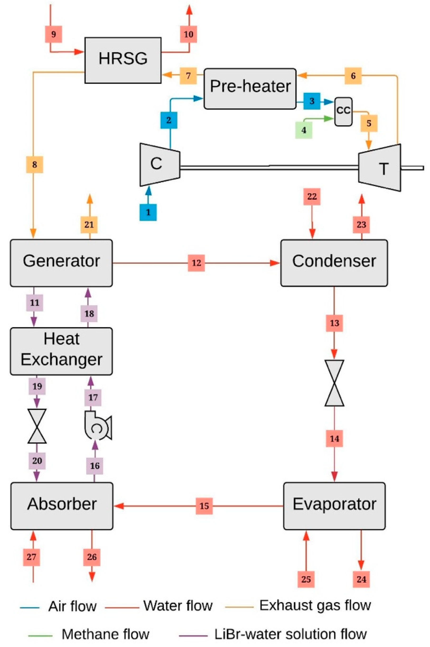
2.1. Description of the System

The physical structure of the trigeneration system is presented in Figure 1. Starting with the gas power cycle, where ambient air at atmospheric pressure (state 1) enters to the compressor, where it is compressed, and its pressure rises, from which it goes out to the preheater (state 2) where it interacts with the exhaust gases of the turbine to increase its temperature and obtain a better combustion.
In the combustion chamber, the air flow (state 3) enters from the preheater at high temperature and pressure, and the methane flow (state 4) enters, which will be burned during mixing with excess air. The modeling of the combustion chamber is obtained, assuming an expansion process of the air, which corresponds to an isobaric process inside the system. The resulting combustion gases (state 5) move the turbine in which the hot gases expand and cool rapidly through an adiabatic expansion, generating the power required for the compressor and the net power of the system.
The output gases of the turbine (state 6) are directed to the preheater equipment where its temperature decreases, and then in the Heat Recovery Steam Generator (HRSG) the heat transfer process allows us to generate the steam (state 10), from the water at ambient temperature (state 9). The exhaust gases (state 8), as an energy source, enters the generator where it separates the solution resulting in an H2O-LiBr mixture with a low concentration (state 11) and the generation of refrigerant saturated steam (state 12). The mixture is modeled as a sub-cooled liquid type (state 19), which expands through a flow valve and arrives at the absorber as a low concentration H2O-LiBr mixture (state 20). On the other hand, the heat is removed inside the condenser heat exchanger from the refrigerant to the environment (state 23), going from a gaseous to a liquid phase (state 13).
In the evaporator heat exchanger, the fluid takes heat from the refrigerated space or room, and induces a phase change in the refrigerant producing a pressure difference between the evaporator and the absorber, where the refrigerant exits as saturated steam (state 15) directly to the absorber, in which there is an energy change between the external water (state 27) and lithium bromide (state 20). As a result, a loop of the lithium bromide mixture is obtained to give a saturated liquid solution (state 16). The pressure of this solution is increased and entered into the heat exchanger by the flow energy supplied by the motor of the pump (state 17) through a counter-current configuration, which increases the temperature to improve efficiency. Finally, the fluid arrives at the generator to continue with the system cycle (state 18).

2.2. Thermodynamic Modeling

In the thermodynamic modeling of the trigeneration system [33], the components of the system are considered as open systems where a steady-state mass balance is applied according to Equation (1). For the case of constant flow systems, such as the generator and absorber, this balance results as shown in Equation (2).
m ˙ o u t = m ˙ i n
m ˙ o u t · x o u t = m ˙ i n · x i n
where x is the concentration, m ˙ o u t and m ˙ i n are the output and input mass flows to the system in kg/s.
Also, the energy balance applied to each component of the trigeneration system based on the first law of thermodynamics is expressed in Equation (3).
Q ˙ W ˙ = m ˙ o u t · h o u t m ˙ i n · h i n
where h is the specific enthalpy in kJ/kg, Q ˙ is heat flow rate in kW, and W ˙ is the power rate in kW.
The performance coefficient of the ARS ( C O P A R S ) is expressed by Equation (4), which is defined as the ratio of the heat transfer of the evaporator ( Q ˙ E v a p o r a t o r ) in kW, and the amount of heat transfer in the generator ( Q ˙ G e n e r ) plus the energy rate of the pump ( W ˙ P ), both in kW.
C O P A R S =   Q ˙ E v a p o r a t o r Q ˙ G e n e r +   W ˙ P
Applying the energy balance to each of the components of the trigeneration system gives the equations shown in Table 1.
To calculate the specific physical exergy ( E ˙ P h ) was not considered the kinetic and potential energy, resulting in the Equation (5).
E ˙ P h = ( h h 0 ) T 0 · ( s s 0 )
where h is the specific enthalpy in kJ/kg, s is the specific entropy in kJ/kg · K of the working fluid flow, h 0 and s 0 are the state enthalpy and entropy at reference condition ( T 0 = 298.15   K and P 0 = 101.325   kPa ).
On the other hand, the chemical exergy for water ( E ˙ w a t e r C h ) was calculated using Equation (6), while for the microturbine exhaust gases (states 6, 7, 8, and 21) was used the Equation (6) since the change of chemical exergy for lithium bromide was not considered.
E ˙ w a t e r C h =   m ˙ · ( z w a t e r M w a t e r ) · E ˙ C h ,   w a t e r 0
E ˙ c h = k = 1 n x k · E ˙ c h k + R · T 0 k = 1 n x k · l n x k
where ( E ˙ Q ,   w a t e r 0 ) is the standard chemical exergy of the water, x k is the molar fraction, and e x c h k is the exergy per mol unit for the k gas.
The exergy balance was applied to each component of the trigeneration system according to Equation (8) [34].
m ˙ i n · E ˙ i n m ˙ o u t · E ˙ o u t + Q ˙ · ( 1 T 0 T ) W ˙ E ˙ D = 0
where m ˙ i n · E ˙ i n is the inflow exergy, m ˙ o u t · E ˙ o u t is the outflow exergy, and E ˙ D is the destroyed exergy.
The exergetic efficiency ( η e x ) based on the second law of thermodynamics, is expressed by the Equation (9).
η e x = E ˙ P E ˙ F
where the amount of fuel exergy ( E ˙ F ) to the system, and the exergy produced ( E ˙ P ) per system are related to the destroyed exergy ( E ˙ D ), and the lost exergy ( E ˙ L ), as shown in Equation (10).
E ˙ F = E ˙ P + E ˙ D + E ˙ L
The Fuel and Product structure in each component of the trigeneration system was calculated, as shown in Table 2.

2.3. Thermo-Economic Analysis

To calculate the total production cost, it is considered the capital investment costs ( Z ˙ C I ), operation and maintenance ( Z ˙ O M ), as shown in Equation (11).
Z ˙ = Z ˙ C I + Z ˙ O M
The equations used to calculate the Purchase Equipment Costs (PEC) for the components of the ARS were: heat exchangers (Equation (12)), pump (Equation (13)), motor (Equation (14)), where the sub-index “0” represents the reference of the studied component [35,36,37].
P E C K =   P E C 0 ,   K · ( A k A 0 ) 0.6
where the reference area ( A 0 ) is 100 m2, the reference costs ( PEC 0 ,   K ) considered are Evaporator ( 16,000 USD), Condenser (8000 USD), Absorber (16,500 USD), and Heat Exchanger (12,000 USD) [26]. Also, the PEC for the pump is calculated based on Equation (13).
P E C p u m p =   P E C 0 , p u m p · ( W ˙ p u m p W ˙ 0 , p u m p ) m B ·   ( 1 η p u m p η p u m p ) n p u m p
where the pump efficiency ( η p u m p ) is 75%, the pump size power ratio ( m B ) is 0.26, and the reference cost ( P E C 0 , p u m p ) is 2100USD. In addition, the model used to estimate the PEC of the pump motor is presented in Equation (14).
P E C m o t =   P E C 0 , m o t · ( W ˙ m o t W ˙ 0 , m o t ) m m o t ·   ( 1 η m o t η m o t ) n m o t
where the motor size power ratio ( m m o t ) is 0.87, the motor reference power ( W ˙ 0 ,   m o t ) is 10 kW, the motor efficiency ( η m o t ) is 90%, the efficiency ratio of motor size ( n m o t ) is 1, and the reference cost ( P E C 0 , m o t ) is 500 USD [26].
The components of the gas microturbine were used some well-known models [26]. For the PEC of the compressor was used the Equation (15), combustion chamber (Equation (16)), and turbine (Equation (17)).
P E C c o m p = ( C 11 · m ˙ a i r C 12 n c o m p ) · ( P a 2 P a 1 ) · l n ( P a 2 P a 1 )
where the compressor coefficients C 11 and C 12 are 71.10 and 0.9 USD / ( kg / s ) , respectively. In addition, the PEC of the combustion chamber was calculated according to Equation 16.
P E C c c = ( C 21 · m ˙ C H 4 C 22 P g c 4 P a 3 ) · [ 1 + e ( C 23 · T 4 C 24 ) ]
where C 21 is 46.08   USD / ( kg / s ) , C 22 is 0.995 , C 23 is 0.018   K 1 and C 24 is 26.4   [26]. Also, for the case of the turbine, Equation (17) was used to calculate the PEC, which is a relevant cost of the microturbine equipment.
P E C t u r b = ( C 31 · m ˙ c o m b C 32 n t u r b ) · ln ( P g c 4 P g c 5 ) [ 1 + e ( C 33 · T 4 C 34 ) ]
where the model turbine coefficients are, C 31 in 479.34   USD / ( kg / s ) , C 32 is 0.92, C 33 is 0.036   K 1 and C 34 is 54.4   [26].
On the other hand, the values of the leveled costs ( P E C L ) by components were calculated by the mean of the Equation (18), which consider the money transactions occur at the end of each year in the economic life of the trigeneration system.
P E C L = C R F · j = 1 n P E C J ( 1 + i e f f ) j
where CRF is the Capital Return Factor, i e f f is the interest rate and P E C j   is the value of the Purchase Equipment Costs in the year j. Also, the CRF is calculated using the Equation (19).
C R F = i e f f ( 1 + i e f f ) n ( 1 + i e f f ) n 1  
where n is the lifetime of the equipment.
To obtain the value of the capital investment in term of unit cost per time ( Z ˙ k ) , without having to calculate leveled costs, the Equation (20) can be used.
Z ˙ k = P E C k · C R F · φ τ  
where τ is the total operation time in hours of the system at full load, and φ is the maintenance factor [38].

2.4. Exergy Cost Balance and Thermo-Economic Indicators

The exergetic cost balance, as shown in Equation (21), the inefficiencies presented in the equipment are evaluated, and the intermediate and final cost of the streams of the thermal process. This analysis allowed us to estimate all exergies of stream in the trigeneration cycle, considering the total costs (acquisition costs, operating costs, and maintenance costs) [39,40,41].
i = 1 n C ˙ o u t , i + C ˙ W , i = i = 1 n C ˙ i n , i + C ˙ Q , i + Z ˙ k
where the terms C ˙ i n , i , and C ˙ o u t , i are the exergy costs associated with the inlet and outlet flow, which are calculated using the Equation (22). The terms C ˙ W , i and C ˙ Q , i are the costs associated with the power and heat transfer exergy cost, which are calculated by the mean of the Equations (23) and (24), respectively.
C i ˙ = c i · E ˙ i
C ˙ W , i = c W · W ˙
C ˙ Q , i = c Q · E ˙ Q
where c i ,   c W and c Q are the specific costs per unit of exergy expressed in dollars per Gigajoules (USD/GJ).
The equations presented in Table 3 are obtained, applying the general cost balances to each component of the trigeneration system. The cost balance can be expressed as shown in Equation (25), as a function of the cost rates of the exergy lost ( C ˙ L , i ), product cost rate ( C ˙ P , i ) according to Equation (26), fuel cost rate ( C ˙ F , i ) attending to Equation (27), and the cost rate of exergy destruction ( C ˙ D , i ) by means of Equation (28).
C ˙ P , i =   C ˙ F , i C ˙ L , i + Z ˙ i
c P , i = C ˙ P , i E ˙ P , i
c F , i = C ˙ F , i E ˙ F , i
C ˙ D , i = c F , i E ˙ D , i
The relative cost difference ( r ) is calculated from the specific fuel and product cost, which shows the average relative cost increase per exergetic unit between the input power and the product, as shown in Equation (29).
r = c P , i c F , i c F , i
Likewise, another thermo-economic indicator studied is the exergo-economic factor ( f ), which measures the relation between the capital cost investment compared to the loss costs rate and exergy destruction, and it is calculated using Equation (30).
f = Z ˙ i Z ˙ i + C ˙ L , i + C ˙ D , i
A high value of this factor reflects a decrease in investment costs by improving energy efficiency, in contrast to low rates of this factor, which suggests saving costs throughout the system for improvement in efficiency.

3. Results and Discussion

This section presents the results of the energetic, exergetic, and thermo-economic analysis of the base case of the trigeneration system, and the parametric study result at different inlet air compressor temperatures. Table 4 presents the thermodynamic properties, physical and chemical exergy of the trigeneration system obtained from the energy balance.
These values allow conducting the exergy balance to calculate the exergy destruction in each component of the system, obtaining the values shown in Figure 2, which presents the percentage of the exergy destruction fraction by equipment and/or components of the system studied.
The exergy destruction represents a loss of useful work that can be taken advantage of by the components of the trigeneration system for the improvement of the operating and thermo-economic conditions. This translates into a great inefficiency and a considerable quantity of energy that must be minimized just when it is needed to maximize the overall thermal efficiency of the process. However, it represents an opportunity to optimize and develop innovate techniques based on new proposals and alternatives of operation and manufacture to design and to rate the devices, all with the purpose of reducing the investment cost associated with the components and, therefore, to the general system.
The results show that the combustion chamber of the gas microturbine is the component with the greatest exergy destruction (29.24%), followed by the generator of the ARS (26.25%). The compressor has a contribution of 0.08% due to the low heat transfer irreversibility presented in this device as a result of the high operating temperature. The greatest amount of exergy destroyed (72%) is located in the combustion chamber, generator and absorber, which suggests a greater technological and operational effort focused on the design of these heat exchange, allowing us to reduce the temperature difference between the fluids. Likewise, from the component cost balances, the exergetic costs of the stream in the system were calculated, as shown in Table 5.
These costs allow us to determine the cost of raw materials, products, and destruction, besides the thermo-economic indicators shown in Table 6. The highest costs are associated with the pre-heater assembly (532.40 USD/GJ), which exceeds the cost of the products obtained by the turbine.

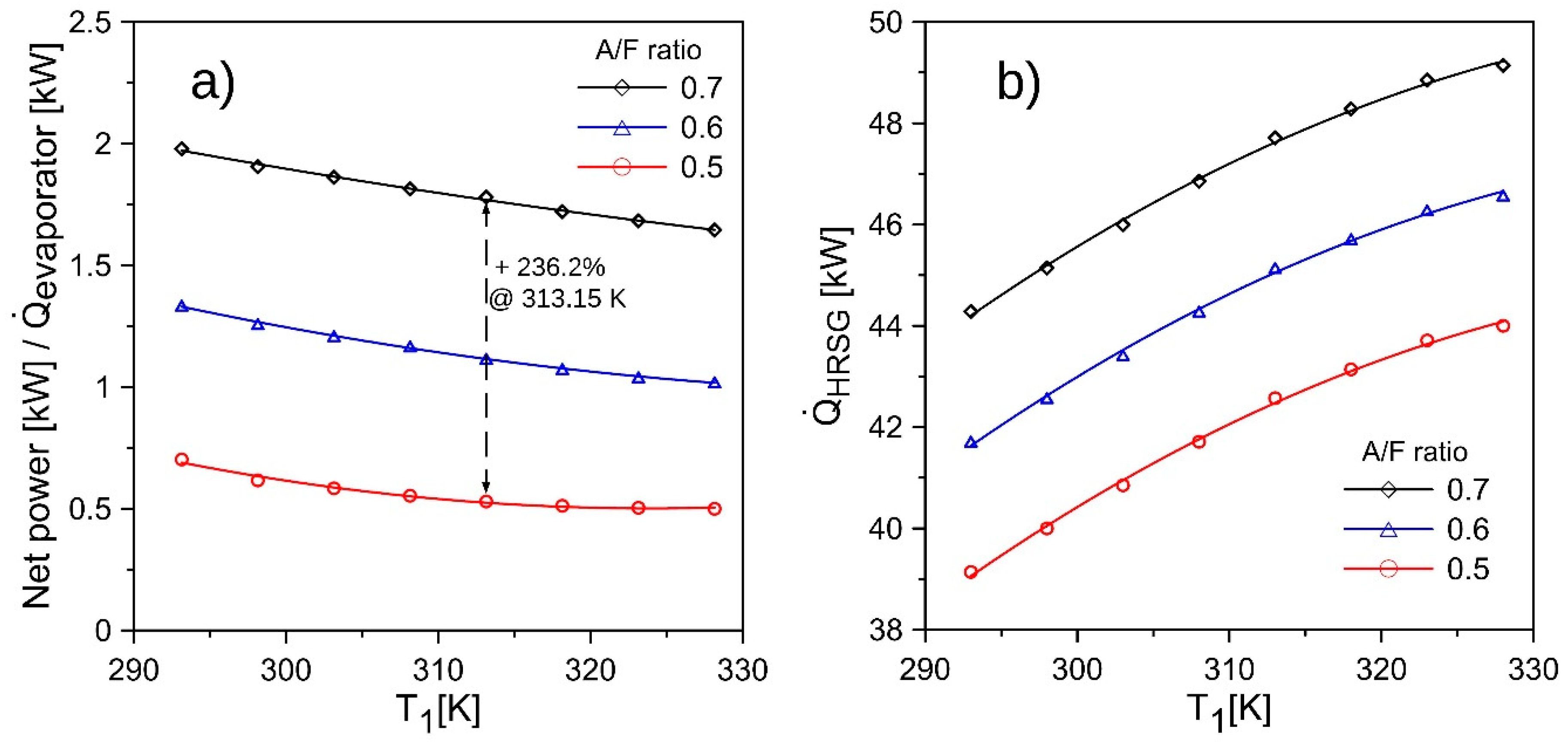
3.1. Energy and Exergy Analysis

This section presents the parametric study results applied in the trigeneration system, through the variation in compressor inlet temperature (T1) from 293.15 K to 328.15 K. The energy performance was evaluated for the microturbine subsystem, HRSG, and the evaporator of the ARS, which will be analyzed and discussed in detail below.
Figure 3a shows that the increase in temperature causes a decrease in the net power supplied by the turbine with respect to the heat absorbed by the evaporator at different air flow ratio, because of the enhancement in the heat removed in the evaporator as a consequence of the increase in the air flow temperature in the inlet compressor. For a given inlet compressor temperature of 313.15 K, the Trigeneration System delivers almost 236.2% power per unit of heat in the evaporator with an air-fuel ratio of 0.7 with respect to 0.5. This means that an increase in the air-fuel ratio causes the microturbine to deliver more power, given the higher airflow. However, the decreasing trend among the studied energy coefficient is preserved, so the inlet compressor temperature is a basic parameter that significantly affects the energy performance of the trigeneration system. On the other hand, the steam energy supplied by the HRGS (Figure 3b) increases with the increase of the air flow inlet compressor temperature, which is due to the improvement of the combustion chamber thermal efficiency, having a combustion with an oxidant both at higher temperature, and more air mass flow by increasing the air-fuel ratio, which increases the thermal capacitance in the HRSG.

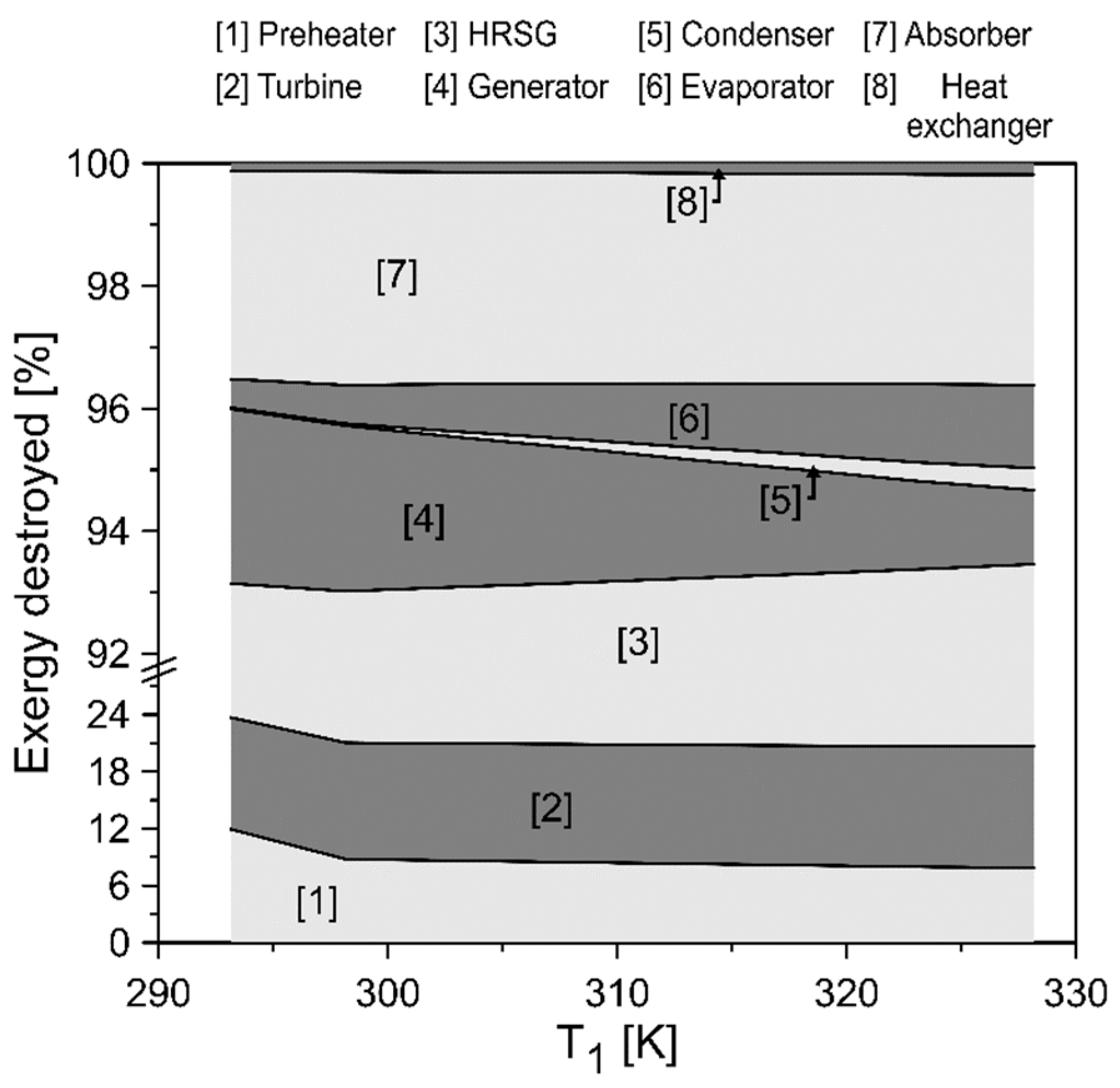
3.2. Exergy Destruction

The exergy destruction analysis by component represents an opportunity for the improvement of the operative and thermo-economic of the thermal system. With this parameter, some alternatives can be developed to reduce the effects of both economic and operational losses. It is important to know the behavior of the minimum and maximum values that can be presented in a device with the purpose of obtaining the possible exergy losses in the trigeneration system and the effect of the increase of the inlet air compressor temperature in the devices of the system that is studied here. The exergy destroyed in the trigeneration system at different compressor inlet air temperatures is shown in Figure 4.
For the exergy destroyed fraction in terms of components, a tendency was observed. We used an accumulation of the percentage losses to obtain a graphical model that describes the behavior of the exergy losses of the general system. With the exclusion of the combustion chamber in the study, we observed a 12% reduction in the exergy destroyed in the turbine until 300 K. Then, it remained at its lowest values while the inlet air compressor temperature increased. Another relevant result is the behavior of the exergy destruction in the generator and condenser, which both present the same range of variation of exergy destroyed (4% to 5%). In this case, below the temperature of 300 K, the exergy destroyed in the generator is greater than the values presented. After this, an increase in temperature caused a significant enhancement of the exergy efficiency of this device at higher compressor inlet air temperature. Therefore, the highest values of exergy destroyed in the devices of the trigeneration system happen when the air temperature is lower than 300 K. However, there are exceptions such as the HRSG and the evaporator, because a higher air temperature limits their functionality in the system.

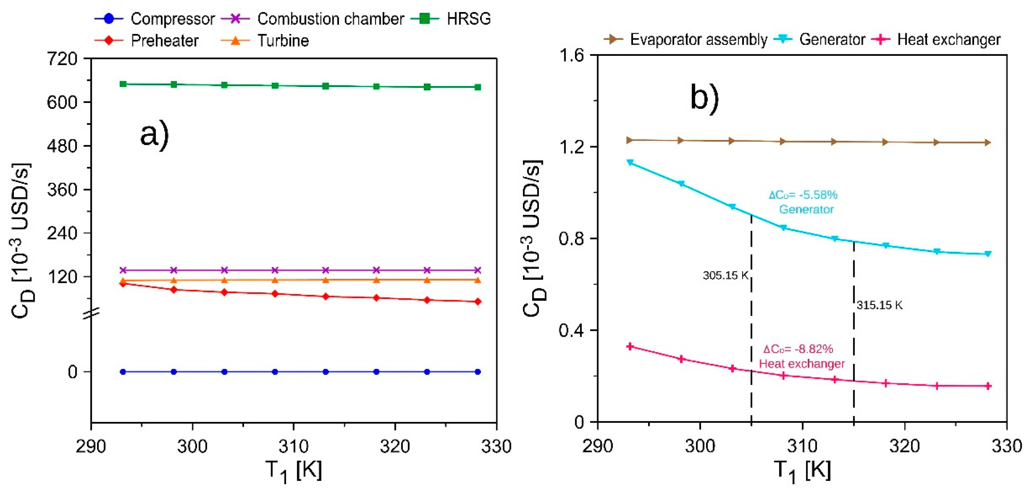
3.3. Cost Rate of Exergy Destruction

The costs related to the exergy destruction represent the economic losses in dollars with respect to the operating time of the system and, therefore, of each one of the components. A comparative analysis of the costs per component of the microturbine is proposed for the variation of the inlet air compressor temperature, while simultaneously analyzing the behavior of the costs related to the exergy destruction in the assembly and different components both in the ARS and microturbine. Figure 5 presents the trends of the cost rate of exergy destruction of the trigeneration system at different compressor inlet air temperatures.
The results show that for the ARS (Figure 5b), both the generator and the heat exchanger decrease their costs as the temperature increases, while in the evaporator assembly there is an unusual behavior which suggests that the variation in the compressor air temperature does not infer exergy destruction or, therefore, related costs. In addition, it is evident that both the evaporator assembly and the heat exchanger have lower costs in the microturbine than in the ARS, which can be explained by the operating conditions of the refrigerant fluids, which directly influence the efficiency of the general system.

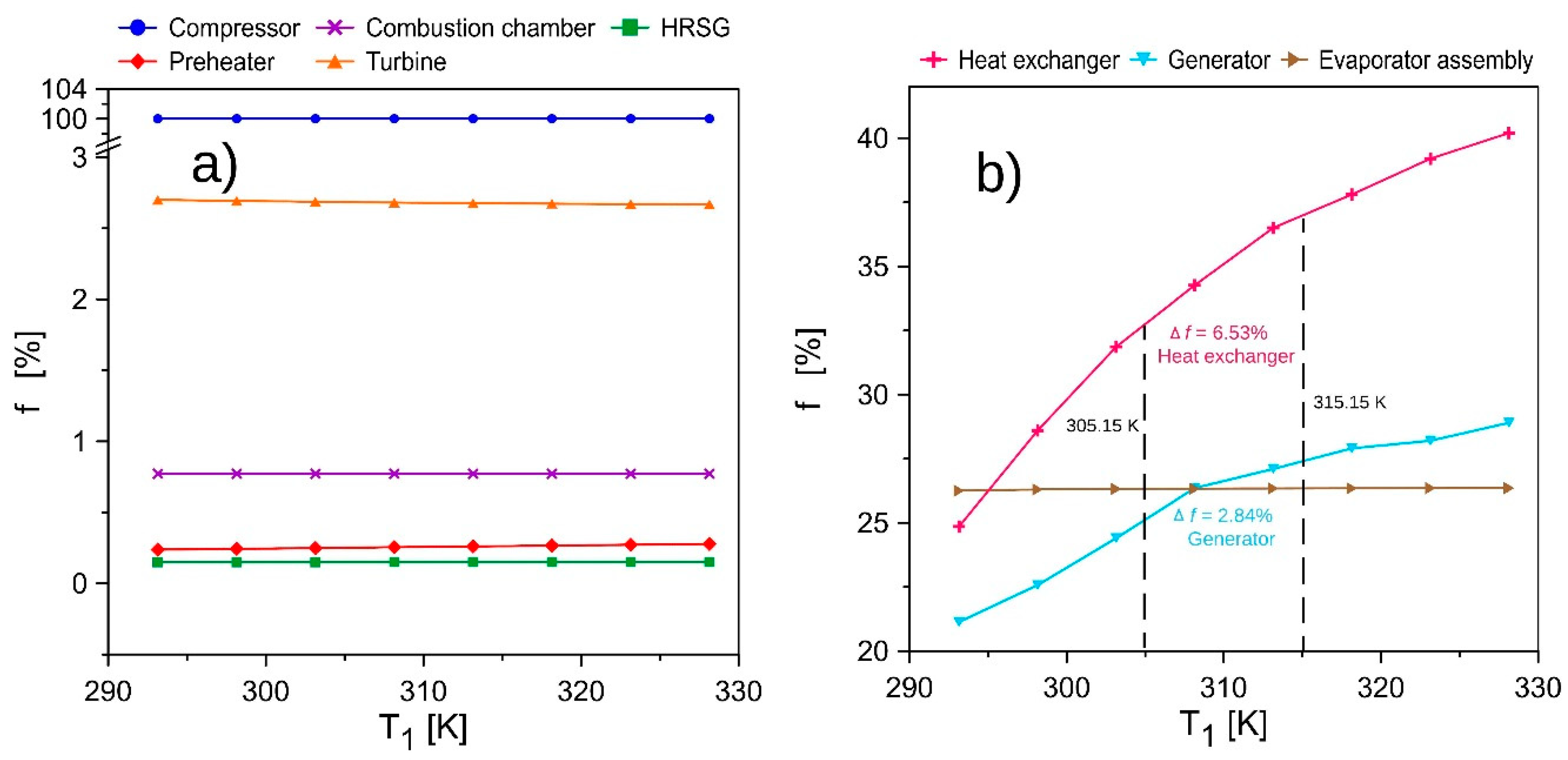
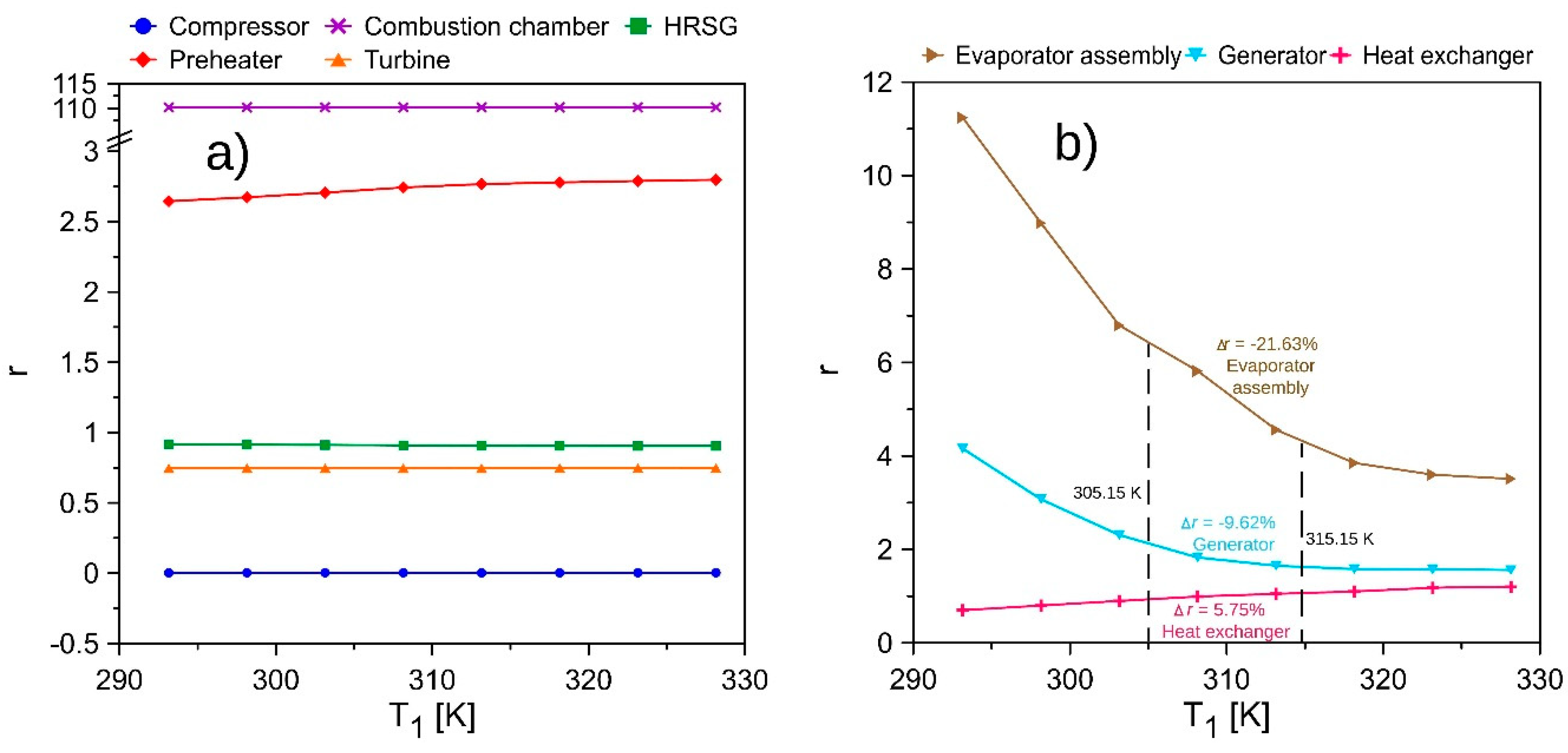
3.4. Relative Cost Difference and Exergo-Economic Factor

The exergo-economic factor results evidenced that, in the systems, there are values of 100% for the compressor and this remains constant for changes of temperature as shown in Figure 6 because the flow energy input in microturbine is free and the destroyed exergy cost rate of the compressor is equal to zero.
Therefore, in the microturbine, the compressor is the equipment in the microturbine with the lowest exergo-economic values, which implies that destruction costs and maintenance costs are relevant in the system. On the other hand, in the ARS system, both the generator and the heat exchanger have high values compared to the microturbine system, which is the same in the relative cost behavior of the evaporator assembly with a very high exergo-economic factor of around 26%. Thus, the ARS has a higher exergo-economic factor than the microturbine system, which is a consequence of high acquisition costs, which are more relevant than the costs for exergy destruction and maintenance, which suggests a reduction of non-fixed costs that can be modified.
In this case, the relative costs increase as the compressor air temperature increases, which indicates a thermodynamic limitation in the system due to the temperature limits allowed. However, a temperature increase of 10 K provides improvements in the overall performance of the microturbine components, while the other subsystem suffers increases of 6.53% and 2.84% of the exergo-economic factor in the heat exchanger and generator, respectively, as shown in Figure 6b.
Figure 7 enables the analysis of the relative cost difference of the main components of the trigeneration systems in this study. Thus, we obtained the tendency of this thermo-economic indicator in a wide range of operations, which allows us to determine the critical equipment that represents the main construction cost of the system and, subsequently, to reduce these costs through design strategies or operational changes of the general thermal system.
In the microturbine subsystem (Figure 7a), the results show a very little effect of the inlet air compressor temperature on the relative costs associated with the different components, which is a consequence of the law variation presented in the exergy destroyed by component and similar values of product and fuel cost in the range of the evaluated temperature.
The results show that, in the case of the ARS, the variation of the compressor inlet temperature causes a decrease in the relative cost of the evaporator assembly (21.63%) with increasing temperature from 305.15 K to 315.15 K, as shown in Figure 7b. However, this behavior does not occur in the entire range studied, which allows us to predict the thermo-economic indicator of the trigeneration system under different ambient temperatures.

4. Conclusions

This study has been carried out considering a trigeneration system with defined limits and considerations. The modification of these considerations and extension of the limits of this process will require an evaluation of some exergetic costs in the exergo-economic model that were not considered, in addition to the exergy required in the condenser, evaporator and absorber currents. The exergetic costs not considered, if evaluated, could compromise the thermo-economic viability of the system, which must be evaluated in detail by means of thermo-economic indicators such as the recovery period of the investment, the specific investment cost and the leveled cost of the energy since this was not defined in the scope of the present study.
The study allowed us to undertake a thermo-economics approach to evaluate energy conversion systems from the energy perspective, and in a broad way, in complement with economic considerations. It also enabled us to verify the real viability of the trigeneration system when it operates with different air temperatures at the inlet of the compressor.
The thermo-economic parametric was developed based on a gas microturbine-ARS–HRSG trigeneration system model, evaluating the different exergy destroyed cost, exergo-economic factor, and relative cost according to each component. The result also showed the opportunities for improvement in components, and the amount of useful energy available that can be recovered from the exhaust gases of the gas microturbine. However, there is an operation condition where the exergy is highly destroyed due to the exergy inefficiencies of the equipment, and a greater purchase equipment cost is presented with a high exergo-economic factor.
In addition, it is concluded that the system is technically and economically viable, which represents a considerable alternative for the implementation in the secondary energy sector, where the cooling and power generation is required, such as the operation of shopping malls, supermarkets, and hotels.

Author Contributions

Conceptualization: G.V.O.; Methodology: G.V.O. and C.A.P.; Software: G.V.O., J.D.F. and C.A.P.; Validation: G.V.O., J.D.F. and C.A.P.; Formal Analysis: G.V.O., J.D.F. and C.A.P.; Investigation: G.V.O.; Resources: G.V.O. and C.A.P.; Writing-Original Draft Preparation: G.V.O.; Writing-Review & Editing: J.D.F. and C.A.P.; Funding Acquisition: G.V.O.

Funding

This work was supported by the Universidad del Atlántico and Universidad Francisco de Paula Santander.

Acknowledgments

The authors are grateful to Universidad del Atlántico, Universidad Francisco de Paula Santander, and Jhonatan De la Cruz for his collaboration received in the case study simulation.

Conflicts of Interest

The authors declare no conflict of interest.

Abbreviations

The following abbreviations are used in this manuscript:
HRSGHeat Recovery Steam Generator
ARSAbsorption Refrigeration System
CRFCapital Recovery Factor
DCDirect cost
CICapital Investment
PECPurchase Equipment Cost
CCCombustion Chamber
TCITotal Capital Investment
OMOperation and Maintenance
Nomenclature
c Specific cost ( USD / GJ )
s Entropy ( kJ / kgK )
C ˙ Associated cost ( USD / s )
E ˙ Exergy (kJ/s)
h Specific enthalpy ( kJ / kg )
m ˙ Mass flow ( kg / s )
Q ˙ Heat transfer ( kJ / s )
R Universal gas constant ( atm   L / mol   K )
P Pressure (bar)
r p m Rotational engine speed (rpm)
T Temperature ( K )
t Time ( s )
W ˙ Power (kW)
X fraction
A Area ( m 2 )
COPPerformance coefficient
i e f f Annual interest rate
nEquipment’s lifetime ( year )
Z ˙ capital investment cost (USD/s)
r Relative cost
f The exergoeconomic factor
Greek Letters
φ Maintenance factor
η Heat recovery efficiency
τ Total operation time (Hr)
Subscripts
e x Exergetic
m o t Motor
k Molar
c o n d Condenser
a b s Absorber
e v a p Evaporator
c h Chemical
p h Physical
o Standard or reference
D Destruction
L Lost
P Produced
k Molar
F Supplied
B Pump size

References

  1. Urbanucci, L.; Testi, D.; Bruno, J.C. Integration of reversible heat pumps in trigeneration systems for low-temperature renewable district heating and cooling microgrids. Appl. Sci. 2019, 9, 3194. [Google Scholar] [CrossRef] [Green Version]
  2. Ramírez, R.; Gutiérrez, A.S.; Eras, J.J.C.; Valencia, K.; Hernández, B.; Forero, J.D. Evaluation of the energy recovery potential of thermoelectric generators in diesel engines. J. Clean. Prod. 2019, 241, 118412. [Google Scholar] [CrossRef]
  3. Valencia, G.; Duarte, J.; Isaza-Roldan, C. Thermoeconomic analysis of different exhaust waste-heat recovery systems for natural gas engine based on ORC. Appl. Sci. 2019, 9, 4017. [Google Scholar] [CrossRef] [Green Version]
  4. Al Moussawi, H.; Fardoun, F.; Louahlia-Gualous, H. Review of tri-generation technologies: Design evaluation, optimization, decision-making, and selection approach. Energy Convers. Manag. 2016, 120, 157–196. [Google Scholar] [CrossRef]
  5. Lecompte, S.; Lemmens, S.; Huisseune, H.; Van den Broek, M.; De Paepe, M. Multi-objective thermo-economic optimization strategy for ORCs applied to subcritical and transcritical cycles for waste heat recovery. Energies 2015, 8, 2714–2741. [Google Scholar] [CrossRef] [Green Version]
  6. Aprhornratana, S.; Eames, I. Thermodynamic analysis of absorption refrigeration cycles using the second law of thermodynamics method. Int. J. Refrig. 1995, 18, 244–252. [Google Scholar] [CrossRef]
  7. Florides, G.A.; Kalogirou, S.A.; Tassou, S.A.; Wrobel, L.C. Modelling, simulation and warming impact assessment of a domestic-size absorption solar cooling system. Appl. Therm. Eng. 2002, 22, 1313–1325. [Google Scholar] [CrossRef]
  8. Shirmohammadi, R.; Soltanieh, M.; Romeo, L. Thermoeconomic analysis and optimization of post-combustion CO2 recovery unit utilizing absorption refrigeration system for a natural-gas-fired power plant. Environ. Prog. Sustain. Energy 2018, 37, 1075–1084. [Google Scholar] [CrossRef]
  9. Valencia, G.; Núñez, J.; Duarte, J. Multiobjective optimization of a plate heat exchanger in a waste heat recovery organic rankine cycle system for natural gas engines. Entropy 2019, 21, 655. [Google Scholar] [CrossRef] [Green Version]
  10. Szargut, J.; Morris, D.; Stewar, F. Exergy Analysis of Thermal, Chemical and Metallurgical Processes; Hemisphere Publishing: New York, NY, USA, 1988. [Google Scholar]
  11. Kotas, T. The Exergy Method of Thermal Plant Analysis; Anchor Brendon Ltd.: London, UK, 1985. [Google Scholar]
  12. Kaynakli, O.; Kilic, M. Theoretical study on the effect of operating conditions on performance of absorption refrigeration system. Energy Convers. Manag. 2007, 48, 599–607. [Google Scholar] [CrossRef]
  13. Martínez, H.; Rivera, W. Energy and exergy analysis of a double absorption heat transformer operating with water/lithium bromide. Int. J. Energy Res. 2009, 33, 662–674. [Google Scholar] [CrossRef]
  14. Kaushik, S.C.; Arora, A. Energy and exergy analysis of single effect and series flow double effect water–lithium bromide absorption refrigeration systems. Int. J. Refrig. 2009, 32, 1247–1258. [Google Scholar] [CrossRef]
  15. Gomri, R.; Hakimi, R. Second law analysis of double effect vapour absorption cooler system. Energy Convers. Manag. 2008, 49, 3343–3348. [Google Scholar] [CrossRef]
  16. Rosiek, S. Exergy analysis of a solar-assisted air-conditioning system: Case study in southern Spain. Appl. Therm. Eng. 2019, 148, 806–816. [Google Scholar] [CrossRef]
  17. Pourfayaz, F.; Imani, M.; Mehrpooya, M.; Shirmohammadi, R. Process development and exergy analysis of a novel hybrid fuel cell-absorption refrigeration system utilizing nanofluid as the absorbent liquid. Int. J. Refrig. 2019, 97, 31–41. [Google Scholar] [CrossRef]
  18. Alanne, K.; Saari, A. Sustainable small-scale CHP technologies for buildings: The basis for multi-perspective decision-making. Renew. Sustain. Energy Rev. 2004, 8, 401–431. [Google Scholar] [CrossRef]
  19. Al-Sulaiman, F.A.; Hamdullahpur, F.; Dincer, I. Trigeneration: A comprehensive review based on prime movers. Int. J. Energy Res. 2011, 35, 233–258. [Google Scholar] [CrossRef]
  20. Mohammadi, S.M.H.; Ameri, M. Energy and exergy analysis of a tri-generation water-cooled air conditioning system. Energy Build. 2013, 67, 453–462. [Google Scholar] [CrossRef]
  21. Fontalvo, A.; Pinzon, H.; Duarte, J.; Bula, A.; Quiroga, A.G.; Padilla, R.V. Exergy analysis of a combined power and cooling cycle. Appl. Therm. Eng. 2013, 60, 164–171. [Google Scholar] [CrossRef]
  22. Diaz, G.A.; Forero, J.D.; Garcia, J.; Rincon, A.; Fontalvo, A.; Bula, A.; Padilla, R.V. Maximum power from fluid flow by applying the first and second laws of thermodynamics. J. Energy Resour. Technol. 2017, 139, 032903. [Google Scholar] [CrossRef]
  23. Marimón, M.A.; Arias, J.; Lundqvist, P.; Bruno, J.C.; Coronas, A. Integration of trigeneration in an indirect cascade refrigeration system in supermarkets. Energy Build. 2011, 43, 1427–1434. [Google Scholar] [CrossRef]
  24. Hawkes, A.D.; Leach, M.A. Cost-effective operating strategy for residential micro-combined heat and power. Energy 2007, 32, 711–723. [Google Scholar] [CrossRef]
  25. Valencia Ochoa, G.; Acevedo Peñaloza, C.; Duarte Forero, J. Thermoeconomic Optimization with PSO Algorithm of Waste Heat Recovery Systems Based on Organic Rankine Cycle System for a Natural Gas Engine. Energies 2019, 12, 4165. [Google Scholar] [CrossRef] [Green Version]
  26. Bejan, A.; Tsatsaronis, G.; Moran, M. Thermal Design and Optimization; John Wiley & Sons: Hoboken, NJ, USA, 1995; ISBN 0471584673. [Google Scholar]
  27. Kizilkan, Ö.; Sencan, A.; Kalogirou, S. Thermoeconomic optimization of a LiBr absorption refrigeration system. Chem. Eng. Process. 2007, 46, 1376–1384. [Google Scholar] [CrossRef]
  28. Lian, Z.T.; Chua, K.J.; Chou, S.K. A thermoeconomic analysis of biomass energy for trigeneration. Appl. Energy 2010, 87, 84–95. [Google Scholar] [CrossRef]
  29. Mago, P.J.; Hueffed, A.K. Evaluation of a turbine driven CCHP system for large office buildings under different operating strategies. Energy Build. 2010, 42, 1628–1636. [Google Scholar] [CrossRef]
  30. Ghaebi, H.; Karimkashi, S.; Saidi, M.H. Integration of an absorption chiller in a total CHP site for utilizing its cooling production potential based on R-curve concept. Int. J. Refrig. 2012, 35, 1384–1392. [Google Scholar] [CrossRef]
  31. Ahmadi, P.; Rosen, M.A.; Dincer, I. Greenhouse gas emission and exergo-environmental analyses of a trigeneration energy system. Int. J. Greenh. Gas Control 2011, 5, 1540–1549. [Google Scholar] [CrossRef]
  32. Ghaebi, H.; Saidi, M.H.; Ahmadi, P. Exergoeconomic optimization of a trigeneration system for heating, cooling and power production purpose based on TRR method and using evolutionary algorithm. Appl. Therm. Eng. 2012, 36, 113–125. [Google Scholar] [CrossRef]
  33. Arregoces, A.J.; De la Cruz, J.R.; Valencia, G.E. Estudio comparativo del desempeño energético, económico y ambiental de un sistema de trigeneración constituido por una microturbina de 30kW acoplada a una tecnología de calefacción y diferentes tecnologías de refrigeración. Univ. Atl. 2019, 1, 123. [Google Scholar]
  34. Moran, M.J.; Saphiro, H.N.; Boettner, D.D.; Bailey, M.B. Fundamentals of Engineering Thermodynamics; Wiley: Hoboken, NJ, USA, 2011; ISBN 978-1-118-10801-7. [Google Scholar]
  35. Garousi Farshi, L.; Mahmoudi, S.M.S.; Rosen, M.A. Exergoeconomic comparison of double effect and combined ejector-double effect absorption refrigeration systems. Appl. Energy 2013, 103, 700–711. [Google Scholar] [CrossRef]
  36. Misra, R.D.; Sahoo, P.K.; Gupta, A. Thermoeconomic optimization of a LiBr/H2O absorption chiller using structural method. J. Energy Resour. Technol. 2005, 127, 119–124. [Google Scholar] [CrossRef]
  37. Boyaghchi, F.A.; Mahmoodnezhad, M.; Sabeti, V. Exergoeconomic analysis and optimization of a solar driven dual-evaporator vapor compression-absorption cascade refrigeration system using water/CuO nanofluid. J. Clean. Prod. 2016, 139, 970–985. [Google Scholar] [CrossRef]
  38. Bilgen, S.; Kaygusuz, K. Second law (exergy) analysis of cogeneration system. Energy Sources Part A 2008, 30, 1267–1280. [Google Scholar] [CrossRef]
  39. Valencia, G.; Fontalvo, A.; Cárdenas, Y.; Duarte, J.; Isaza, C. Energy and exergy analysis of different exhaust waste heat recovery systems for natural gas engine based on ORC. Energies 2019, 12, 2378. [Google Scholar] [CrossRef] [Green Version]
  40. Ochoa, G.V.; Peñaloza, C.A.; Rojas, J.P. Thermoeconomic modelling and parametric study of a simple ORC for the recovery of waste heat in a 2 MW gas engine under different working fluids. Appl. Sci. 2019, 9, 4526. [Google Scholar] [CrossRef] [Green Version]
  41. Valencia, G.; Benavides, A.; Cárdenas, Y. Economic and Environmental Multiobjective Optimization of a Wind–Solar–Fuel Cell Hybrid Energy System in the Colombian Caribbean Region. Energies 2019, 12, 2119. [Google Scholar] [CrossRef] [Green Version]
Figure 1. Physical structure of the trigeneration system.
Energies 12 04643 g001
Figure 2. Percentage Exergy Destruction for each component of the trigeneration system.
Energies 12 04643 g002
Figure 3. Energy performance of the trigeneration system at different compressor inlet air temperatures, (a) Net Power/Evaporator heat, and (b) Heat in the Heat Recovery Steam Generator (HRSG).
Energies 12 04643 g003
Figure 4. Exergy destroyed in the trigeneration system at different compressor inlet air temperatures.
Energies 12 04643 g004
Figure 5. Cost rate of exergy destruction of the trigeneration system at different compressor inlet air temperatures, (a) microturbine components, and (b) absorption chiller components.
Energies 12 04643 g005
Figure 6. Exergoeconomic factor of the trigeneration system at different compressor inlet air temperatures, (a) microturbine components, and (b) absorption chiller components.
Energies 12 04643 g006
Figure 7. Relative cost difference of the trigeneration system at different compressor inlet air temperatures, (a) Microturbine components, and (b) Absorption chiller components.
Energies 12 04643 g007
Table 1. Energy balance equations by components of the trigeneration system.
ComponentEnergy Balance
Compressor m ˙ 1 · h 1 + W ˙ c o m p m ˙ 2 · h 2 = 0
Combustion Chamber ( m ˙ 3 · h 3 + m ˙ 4 · h 4 ) · n c c m ˙ 5 · h 5 = 0
Turbine m ˙ 5 · h 5 W ˙ t u r b m ˙ 6 · h 6 = 0
Pre-heater m ˙ 7 · h 7 m ˙ 6 · h 6 = m ˙ 3 · h 3 m ˙ 2 · h 2
HRSG m ˙ 7 · h 7 Q ˙ H R S G + m ˙ 8 · h 8 = 0
Generator m ˙ 18 · h 18 + Q ˙ g e n e r m ˙ 12 · h 12 m ˙ 11 · h 11 = 0
Condenser m ˙ 12 · h 12 m ˙ 13 · h 13 + Q ˙ c o n d = 0
Evaporator m ˙ 13 · h 13 + Q ˙ e v a p m ˙ 15 · h 15 = 0
Absorber m ˙ 15 · h 15 + m ˙ 20 · h 20 m ˙ 16 · h 16 + Q ˙ a b s = 0
Heat exchanger m ˙ 17 · h 17 + m ˙ 11 · h 11 m ˙ 18 · h 18 + m ˙ 20 · h 20 = 0
Table 2. Fuel and Product exergy equations.
Component E ˙ F E ˙ P E ˙ L
Compressor W ˙ c o m p E ˙ 2 E ˙ 1 -
Air pre-heater E ˙ 6 E ˙ 7 E ˙ 3 E ˙ 2 -
Combustion Chamber E ˙ 4 E ˙ 5 E ˙ 3 -
Turbine E ˙ 5 E ˙ 6 W ˙ t u r b -
HRSG E ˙ 7 E ˙ 8 E ˙ 9 E ˙ 10 -
Generator E ˙ 8 E ˙ 21 E ˙ 12 + E ˙ 11 E ˙ 18 E ˙ 21
Condenser-- E ˙ 23
Evaporator E ˙ 14 E ˙ 15 E ˙ 24 E ˙ 25 -
Absorber E ˙ 16 E ˙ 15 E ˙ 20 E ˙ 27 E ˙ 26 -
Heat exchanger E ˙ 11 E ˙ 19 E ˙ 18 E ˙ 17 -
Table 3. Cost balance equation by components.
ComponentCost Balance EquationsAuxiliary Equations
Compressor C ˙ 1 + C ˙ c o m p + Z ˙ c o m p = C ˙ 2 C ˙ 1 = 0
Air preheater C ˙ 2 + C ˙ 6 + Z ˙ p h = C ˙ 3 + C ˙ 7 C ˙ 7 E ˙ 7 = C ˙ 7 E ˙ 6
Combustion chamber C ˙ 3 + C ˙ 4 + Z ˙ c c = C ˙ 5 C ˙ 4 = 139.18
Turbine C ˙ 5 + Z ˙ t u r b = C ˙ 6 + C ˙ c o m p + C ˙ t u r b C ˙ 6 E ˙ 6 = C ˙ 5 E ˙ 5 , C ˙ c o m p W ˙ c o m p = C ˙ t u r b W ˙ t u r b
HRSG C ˙ 7 + C ˙ 10 + Z ˙ H R S G = C ˙ 8 + C ˙ 9 C ˙ 8 E ˙ 8 = C ˙ 7 E ˙ 7
C ˙ 10 = 0
Generator C ˙ g e n + C ˙ 18 + Z ˙ g e n = C ˙ 12 + C ˙ 11
C ˙ 12 m ˙ water   ( e x 12 e x 18 ) C ˙ 18 ( e x 11 e x 12 ) m ˙ t   ( e x 12 e x 18 ) ( e x 11 e x 18 ) C ˙ 11 m ˙ pump   ( e x 11 e x 18 ) = 0
-
Heat exchanger C ˙ 17 + C ˙ 11 + Z ˙ h e = C ˙ 18 + C ˙ 19 C ˙ 11 E ˙ 11 = C ˙ 19 E ˙ 19
Pump C ˙ p u m p + C ˙ 16 + Z ˙ p u m p = C ˙ 17 -
Condenser C ˙ 12 + Z ˙ c o n d = C ˙ 13 + Δ C ˙ c o n d C ˙ 12 E ˙ 12 = C ˙ 13 E ˙ 13
Absorber C ˙ 20 + C ˙ 15 + Z ˙ a b s = C ˙ 16 + Δ C ˙ a b s C ˙ 20 + C ˙ 15 E ˙ 20 + E ˙ 15 = C ˙ 16 E ˙ 16
Evaporator- C ˙ 14 E ˙ 14 = C ˙ 15 E ˙ 15
Solution expansion valve- C ˙ 19 E ˙ 19 = C ˙ 20 E ˙ 20
Coolant expansion valve- C ˙ 13 E ˙ 13 = C ˙ 14 E ˙ 14
Table 4. Thermodynamic properties, physical and chemical exergy of the trigeneration system.
State m ˙
[kg/s]
T
[K]
P
[bar]
h
[kJ/kg]
s
[kJ/kg·K]
E ˙ P h
[kJ/s]
E ˙ c h
[kJ/s]
10.30298.151.013298.605.6900
20.30452.103.64454.316.1646.710
30.30673.203.61684.836.1673.830
40.50298.153.70-3.62−0.6899.722.5919
5 0.80829.103.61216.407.69305.404.24
60.80745.201.081120.817.92174.604.24
70.805401.051−108.107.5775.114.24
80.80346.501.021−314.907.1020.544.24
90.065372.300.9826517.3629.85617.50
100.065298.151.013104.810.3600
110.57346.500.059167.910.4423.600.62
120.019346.500.05926378.541.840.049
130.019309.200.059150.810.520.0140.049
140.019278.200.0087150.800.54−0.130.049
150.019278.200.008725109.024−3.490.049
160.59307.200.008781.380.2014.190.66
170.59307.200.05981.380.2014.190.66
180.59331.500.059131.200.3616.0810.66
190.57322.900.059120.200.2920.630.62
200.57310.900.0087120.200.2233.510.62
Table 5. Exergetic cost rates ( C ˙ ) in USD/s, and the costs per unit of exergy of the stream (c) in USD/GJ.
State C ˙ [10−3 USD/s] c [USD/GJ]State C ˙ [10−3 USD/s] c [USD/GJ]
100113.1825.73
289.53532.4120.4224.27
3198.50746.9130.01424.27
4139.211.48140.01724.27
5338.70303.88150.7524.27
6195.61303.87161.3926.14
786.81303.89171.4827.80
827.12303.88181.8630.89
960.67303.90192.8525.73
1000203.6125.73
Table 6. Average costs per unit of fuel ( C ˙ F , i ) and product ( C ˙ P , i   ) , destruction cost ( C ˙ D , i ) , relative cost difference (r), and exergo-economic factor (f) for each component of the trigeneration system.
Equipment C ˙ F , i   [ U S D / s ] C ˙ P , i   [ U S D / s ] C ˙ D , i [ U S D / s ] rf
Compressor24.8024.8700.00311
Pre-heater30.2230.2779.132.670.0024
Combustion chamber38.6638.95137.91110.200.0072
Turbine39.7515.80110.500.750.027
HRSG16.5816.85648.510.910.0015
Generator12.9422.0310.430.700.41
Assembly evaporator26.35132.701.114.300.28
Heat exchanger27.1565.770.151.420.41

