Investigation of Corrosion Methods for Bipolar Plates for High Temperature Polymer Electrolyte Membrane Fuel Cell Application

 , , and
Abstract
1. Introduction
2. Materials and Methods
2.1. BPP Samples
2.2. Imaging Methods
2.3. Chemical and Electrochemical Aging
2.3.1. Method I
2.3.2. Method II
3. Results and Discussion
3.1. Method I
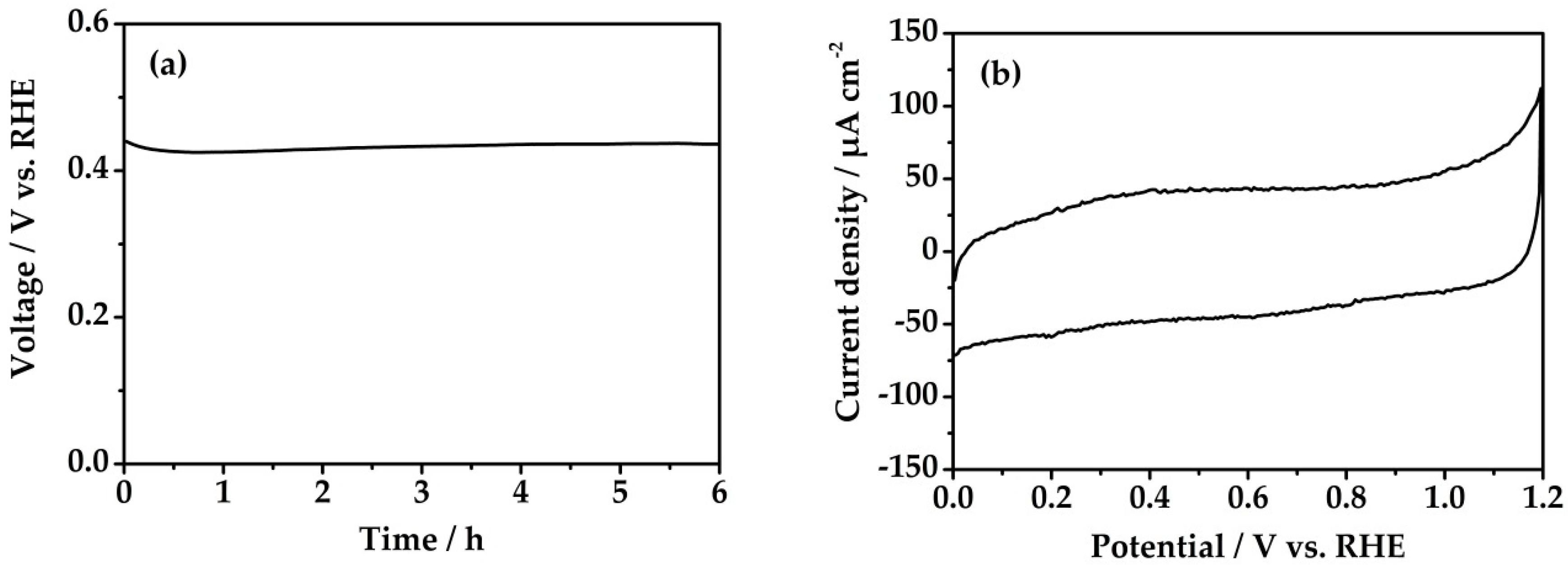
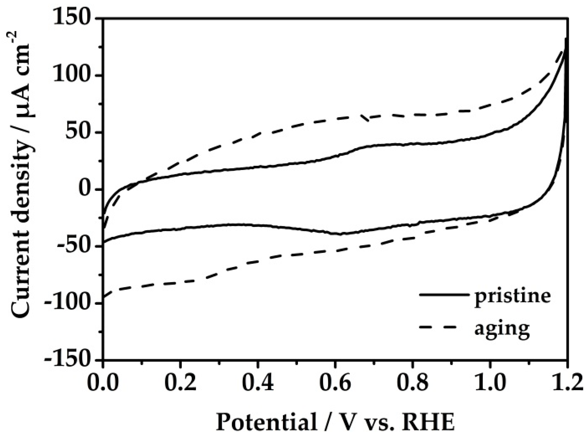
3.2. Method II
4. Conclusions
Author Contributions
Funding
Acknowledgments
Conflicts of Interest
References
- Rosli, R.E.; Sulong, A.B.; Daud, W.R.W.; Zulkifley, M.A.; Husaini, T.; Rosli, M.I.; Majlan, E.H.; Haque, M.A. A review of high-temperature proton exchange membrane fuel cell (HT-PEMFC) system. Int. J. Hydrogen Energy 2017, 42, 9293–9314. [Google Scholar] [CrossRef]
- Chandan, A.; Hattenberger, M.; El-Kharouf, A.; Du, S.; Dhir, A.; Self, V.; Pollet, B.G.; Ingram, A.; Bujalski, W. High temperature (HT) polymer electrolyte membrane fuel cells (PEMFC)—A review. J. Power Sources 2013, 231, 264–278. [Google Scholar] [CrossRef]
- Araya, S.S.; Zhou, F.; Liso, V.; Sahlin, S.L.; Vang, J.R.; Thomas, S.; Gao, X.; Jeppesen, C.; Kær, S.K. A comprehensive review of PBI-based high temperature PEM fuel cells. Int. J. Hydrogen Energy 2016, 41, 21310–21344. [Google Scholar] [CrossRef]
- Lopes de Oliveira, M.C.; Sayeg, I.J.; Ett, G.; Antunes, R.A. Corrosion behavior of polyphenylene sulfide–carbon black–graphite composites for bipolar plates of polymer electrolyte membrane fuel cells. Int. J. Hydrogen Energy 2014, 39, 16405–16418. [Google Scholar] [CrossRef]
- Cruz-Gonzales, T. Theory of Proton Exchange Membranes Fuel Cells and the Testing of Performance Characteristics of Polymer Electrolyte Membranes; Massachuesetts Institute of Technology: Cambridge, MA, USA, 2004. [Google Scholar]
- Asensio, J.A.; Sanchez, E.M.; Gomez-Romero, P. Proton-conducting membranes based on benzimidazole polymers for high-temperature PEM fuel cells. A chemical quest. Chem. Soc. Rev. 2010, 39, 3210–3239. [Google Scholar] [CrossRef]
- De Bruijn, F.A.; Dam, V.A.T.; Janssen, G.J.M. Review: Durability and degradation issues of PEM fuel cell components. Fuel Cells 2008, 8, 3–22. [Google Scholar] [CrossRef]
- Kuan, H.-C.; Ma, C.-C.M.; Chen, K.H.; Chen, S.-M. Preparation, electrical, mechanical and thermal properties of composite bipolar plate for fuel cell. J. Power Sources 2004, 134, 7–17. [Google Scholar] [CrossRef]
- Hermann, A.; Chaudhuri, T.; Spagnol, P. Bipolar plates for PEM fuel cells: A review. Int. J. Hydrogen Energy 2005, 30, 1297–1302. [Google Scholar] [CrossRef]
- Cunningham, B.D.; Huang, J.; Baird, D.G. Development of bipolar plates for fuel cells from graphite filled wet-lay material and a thermoplastic laminate skin layer. J. Power Sources 2007, 165, 764–773. [Google Scholar] [CrossRef]
- Alegre, C.; Álvarez-Manuel, L.; Mustata, R.; Valiño, L.; Lozano, A.; Barreras, F. Assessment of the durability of low-cost Al bipolar plates for High Temperature PEM fuel cells. Int. J. Hydrogen Energy 2019, 44, 12748–12759. [Google Scholar] [CrossRef]
- Barreras, F.; Lozano, A.; Roda, V.; Barroso, J.; Martín, J. Optimal design and operational tests of a high-temperature PEM fuel cell for a combined heat and power unit. Int. J. Hydrogen Energy 2014, 39, 5388–5398. [Google Scholar] [CrossRef]
- Hartnig, C.; Schmidt, T.J. On a new degradation mode for high-temperature polymer electrolyte fuel cells: How bipolar plate degradation affects cell performance. Electrochim. Acta 2011, 56, 4237–4242. [Google Scholar] [CrossRef]
- Rungsima, Y.; Michael, F.; Costas, T. A review of thermoplastic composites for bipolar plate materials in pem fuel cells. In Nanocomposites with Unique Properties and Applications in Medicine and Industry; Cuppoletti, J., Ed.; Intech: Vienna, Austria, 2011; pp. 317–344. [Google Scholar] [CrossRef]
- Hamilton, P.J.; Pollet, B.G. Polymer electrolyte membrane fuel cell (PEMFC) flow field plate: Design, materials and characterisation. Fuel Cells 2010, 4, 489–509. [Google Scholar] [CrossRef]
- Taherian, R. A review of composite and metallic bipolar plates in proton exchange membrane fuel cell: Materials, fabrication, and material selection. J. Power Sources 2014, 265, 370–390. [Google Scholar] [CrossRef]
- Antunes, R.A.; de Oliveira, M.C.L.; Ett, G.; Ett, V. Carbon materials in composite bipolar plates for polymer electrolyte membrane fuel cells: A review of the main challenges to improve electrical performance. J. Power Sources 2011, 196, 2945–2961. [Google Scholar] [CrossRef]
- Engl, T.; Gubler, L.; Schmidt, T.J. Think different! Carbon corrosion mitigation strategy in high temperature PEFC: A rapid aging study. J. Electrochem. Soc. 2015, 162, F291–F297. [Google Scholar] [CrossRef]
- Rodrigues Castanheira, L.F. Corrosion of High Surface Area Carbon Supports Used in Proton-Exchange Membrane Fuel Cell Electrodes. Ph.D. Thesis, Université de Grenoble, Grenoble, France, 2014. [Google Scholar]
- Dhakate, S.R.; Mathur, R.B.; Kakati, B.K.; Dhami, T.L. Properties of graphite-composite bipolar plate prepared by compression molding technique for PEM fuel cell. Int. J. Hydrogen Energy 2007, 32, 4537–4543. [Google Scholar] [CrossRef]
- Kakati, B.K.; Sathiyamoorthy, D.; Verma, A. Electrochemical and mechanical behavior of carbon composite bipolar plate for fuel cell. Int. J. Hydrogen Energy 2010, 35, 4185–4194. [Google Scholar] [CrossRef]
- Satola, B.; Komsiyska, L.; Wittstock, G. Corrosion of graphite-polypropylene current collectors during overcharging in negative and positive vanadium redox flow battery half-cell electrolytes. J. Electrochem. Soc. 2018, 165, A963–A969. [Google Scholar] [CrossRef]
- Wang, L.-N.; Luo, J.-L. Electrochemical behaviour of anodic zirconium oxide nanotubes in simulated body fluid. Appl. Surf. Sci. 2012, 258, 4830–4833. [Google Scholar] [CrossRef]
- Bolat, G.; Mareci, D.; Chelariu, R.; Izquierdo, J.; González, S.; Souto, R.M. Investigation of the electrochemical behaviour of TiMo alloys in simulated physiological solutions. Electrochim. Acta 2013, 113, 470–480. [Google Scholar] [CrossRef]
- Cimenti, M.; Co, A.C.; Birss, V.I.; Hill, J.M. Distortions in Electrochemical Impedance Spectroscopy Measurements Using 3-Electrode Methods in SOFC. I—Effect of Cell Geometry. Fuel Cells 2007, 7, 364–376. [Google Scholar] [CrossRef]
- Battistel, A.; Fan, M.; Stojadinović, J.; La Mantia, F. Analysis and mitigation of the artefacts in electrochemical impedance spectroscopy due to three-electrode geometry. Electrochim. Acta 2014, 135, 133–138. [Google Scholar] [CrossRef]
- Satola, B.; Kirchner, C.N.; Komsiyska, L.; Wittstock, G. Chemical stability of graphite-polypropylene bipolar plates for the vanadium redox flow battery at resting state. J. Electrochem. Soc. 2016, 163, A2318–A2325. [Google Scholar] [CrossRef]
- Satola, B.; Komsiyska, L.; Wittstock, G. Bulk aging of graphite-polypropylene current collectors induced by electrochemical cycling in the positive electrolyte of vanadium redox flow batteries. J. Electrochem. Soc. 2017, 164, A2566–A2572. [Google Scholar] [CrossRef]
- Kinoshita, K.; Bett, J.A.S. Potentiodynamic analysis of surface oxides on carbon blacks. Carbon 1973, 11, 403–411. [Google Scholar] [CrossRef]
- Choo, H.-S.; Kinumoto, T.; Jeong, S.-K.; Iriyama, Y.; Abe, T.; Ogumi, Z. Mechanism for electrochemical oxidation of highly oriented pyrolytic graphite in sulfuric acid solution. J. Electrochem. Soc. 2007, 154, B1017–B1023. [Google Scholar] [CrossRef]
- Dushina, A.; Satola, B.; Dyck, A.; Wagner, P. Comparative investigation of polyphenylene sulfide polymer-graphite bipolar plates for fuel cell application. ECS Trans. 2019, 92, 361–373. [Google Scholar] [CrossRef]
- Lee, H.S.; Kim, H.J.; Kim, S.G.; Ahn, S.H. Evaluation of graphite composite bipolar plate for PEM (proton exchange membrane) fuel cell: Electrical, mechanical, and molding properties. J. Mater. Process. Technol. 2007, 187–188, 425–428. [Google Scholar] [CrossRef]
- Jaiswal, A.; Chalasani, S.C. The role of carbon in the negative plate of the lead–acid battery. J. Energy Storage 2015, 1, 15–21. [Google Scholar] [CrossRef]
- Goulet, M.-A.; Skyllas-Kazacos, M.; Kjeang, E. The importance of wetting in carbon paper electrodes for vanadium redox reactions. Carbon 2016, 101, 390–398. [Google Scholar] [CrossRef]
- Chmiola, J.; Yushin, G.; Dash, R.K.; Hoffman, E.N.; Fischer, J.E.; Barsoum, M.W.; Gogotsi, Y. Double-layer capacitance of carbide derived carbons in sulfuric acid. Electrochem. Solid State Lett. 2005, 8, A357–A360. [Google Scholar] [CrossRef]


© 2020 by the authors. Licensee MDPI, Basel, Switzerland. This article is an open access article distributed under the terms and conditions of the Creative Commons Attribution (CC BY) license (http://creativecommons.org/licenses/by/4.0/).
Share and Cite
Pilinski, N.; Käding, C.; Dushina, A.; Hickmann, T.; Dyck, A.; Wagner, P. Investigation of Corrosion Methods for Bipolar Plates for High Temperature Polymer Electrolyte Membrane Fuel Cell Application. Energies 2020, 13, 235. https://doi.org/10.3390/en13010235
Pilinski N, Käding C, Dushina A, Hickmann T, Dyck A, Wagner P. Investigation of Corrosion Methods for Bipolar Plates for High Temperature Polymer Electrolyte Membrane Fuel Cell Application. Energies. 2020; 13(1):235. https://doi.org/10.3390/en13010235
Chicago/Turabian StylePilinski, Nadine, Claudia Käding, Anastasia Dushina, Thorsten Hickmann, Alexander Dyck, and Peter Wagner. 2020. "Investigation of Corrosion Methods for Bipolar Plates for High Temperature Polymer Electrolyte Membrane Fuel Cell Application" Energies 13, no. 1: 235. https://doi.org/10.3390/en13010235
APA StylePilinski, N., Käding, C., Dushina, A., Hickmann, T., Dyck, A., & Wagner, P. (2020). Investigation of Corrosion Methods for Bipolar Plates for High Temperature Polymer Electrolyte Membrane Fuel Cell Application. Energies, 13(1), 235. https://doi.org/10.3390/en13010235