1. Introduction
Natural gas hydrate is regarded as a kind of potential energy source, since it has several preponderant characteristics, such as high energy density and cleanliness, large reserve, shallow burial, among others [
1,
2]. Under the standard conditions of recovery, natural gas would break down into large volumes of methane and water, which has an enormous influence on marine geological change, climate change, drilling safety, and so on. The stability of methane gas hydrate requires the relatively favorable conditions of low temperature and pressure, which limit the occurrence of methane hydrate in nature primarily to marine continental slope sediments as well as in and beneath permafrost.
Recovery in situ pressure can ensure the authenticity of the cores to the greatest extent, by which the pressure core is taken in geological formations [
3]. At present, the analysis and processing system applied for the natural gas hydrate pressure core is being developed rapidly by research centers from all over the world, which can help scientists understand the physical and chemical properties, and the geological structure [
4].
MSCL (Multi-Sensor Core Logger) is a non-disturbing sample analysis tool developed by the Geotek Corporation of the United Kingdom. The MSCL system can be applied to pressure cores or seafloor sediments. It can quickly acquire high-resolution data from pressure cores or seafloor sediments without damaging the sample structure [
5,
6]. Based on MSCL, the UK Geotek Company has further developed the Pressure Core Analysis and Transfer System (PCATS), an essential device for gas hydrate investigation and analysis. PCATS links the drilling pipe filled with pressure cores to investigators [
7], transferring cores from the individual coring autoclaves into a measurement device [
8]. So far, the deployment of HYACE tools in new tests on hydrates (HYCHINTH) has been used for four major gas hydrate expeditions for the quantification of gas hydrate and detailed measurements on gas-hydrate-bearing sediments [
9]. This system not only has sampling tools, but also a range of processing equipment for pressure cores. Based on the MALLIK Mobile Core Laboratory, physical property analysis of natural gas hydrate cores was carried out under constant temperature conditions, including gamma density, longitudinal wave velocity, and shear wave velocity, infrared temperature, and a CT test [
10].
To preserve gas hydrate stability, pressure cores need to be retrieved at high pressure from coring autoclaves for further testing or storage; thus, the driving device is required to transfer and sub-sample cores while maintaining in situ pressure and temperature conditions. Nowadays, the PCATs manipulator has been redesigned to prevent the excessive length of the original version by using a ball-screw mechanism that operates in parallel with the core [
11]. However, there are no relevant papers to expound the working principle or relevant sea trails currently. The purpose of this paper is to describe the driving device for pressure core, which is the basis and core part of the Analysis and Transfer System of Natural Gas Hydrate Pressure Core (
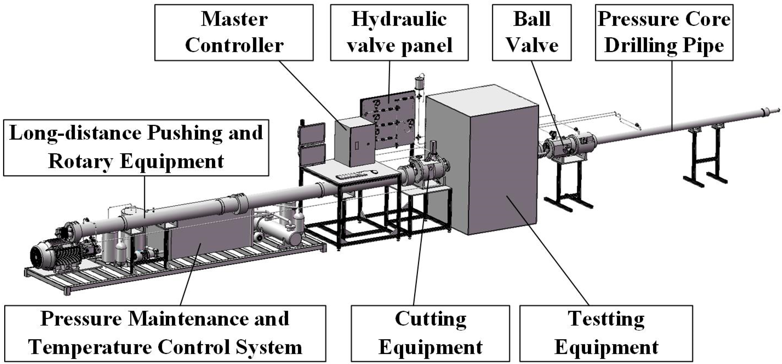
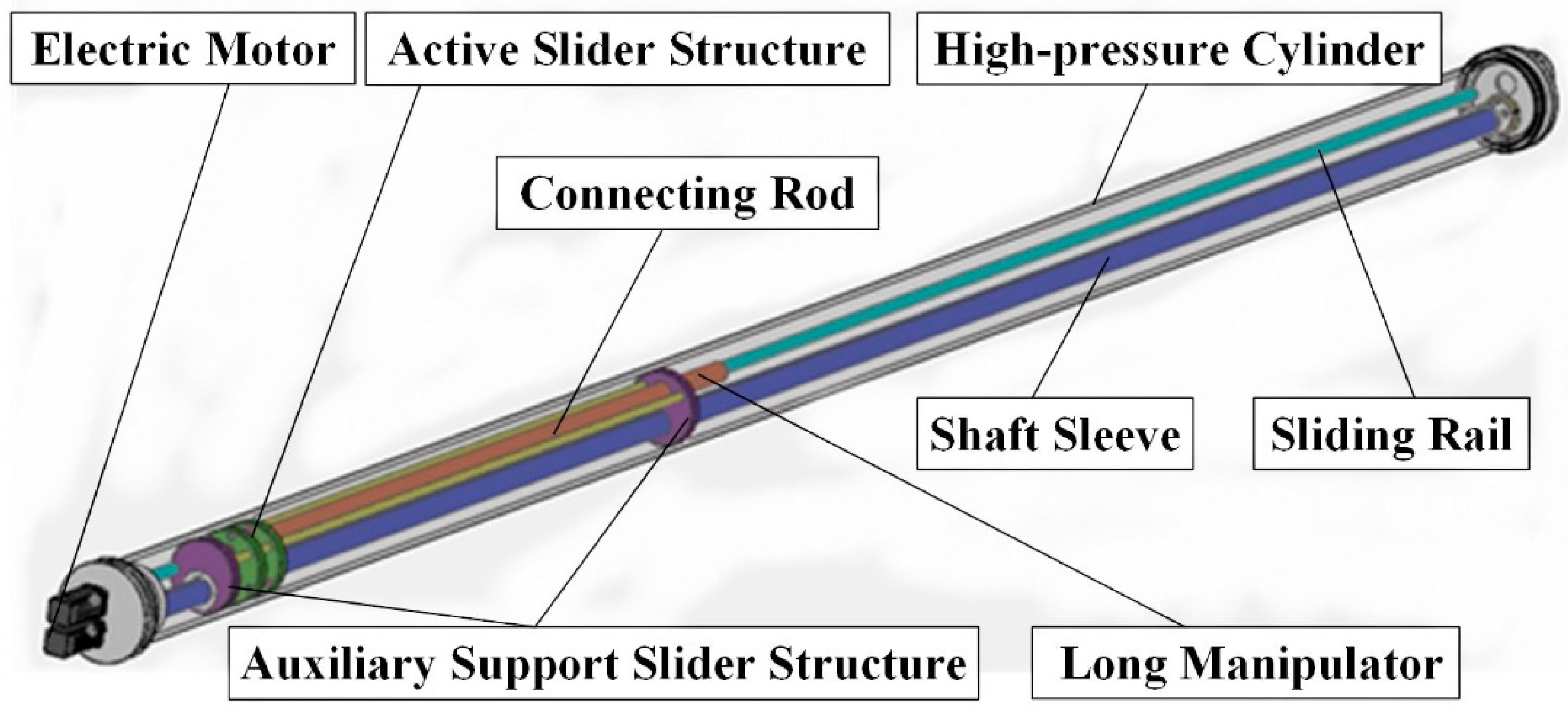
Figure 1). Both temperature and pressure are maintained through the hydraulic fluid (seawater or freshwater) and monitored continuously. Under the in situ temperature (2–4 °C) and pressure up to 300 bar (30 MPa), this device meets the engineering demand of long-distance transmission from the compatible drilling pipes to the high-pressure cylinder, as well as transmission into other chambers soon after nondestructively analyzing and precisely cutting the whole subsamples of core. Except for core motion, core rotation is another integral part, whose mechanism is a necessity for the analysis and transfer system of natural gas hydrate pressure core, ensuring the core subsection and the X-ray imaging to work well.
2. Design of Driving Device
By the driving device, a pressure core up to 3 m in length can be transferred from pressure core drilling tools to the high-pressure cylinder, which prevents either visual inspection or manual intervention, under the in-situ temperature (2–4 °C) and pressures up to 300 bar (30 MPa). Furthermore, this device also makes the pressure core rotate when the pressure core is transferred to the testing equipment. The precise translational and rotational capability of pressure core ensures that complex structural features can be tested in detail through high-resolution X-ray and sonic wave. Finally, the feasibility of this device is verified by a series of theoretical analysis and experiments.
As shown in
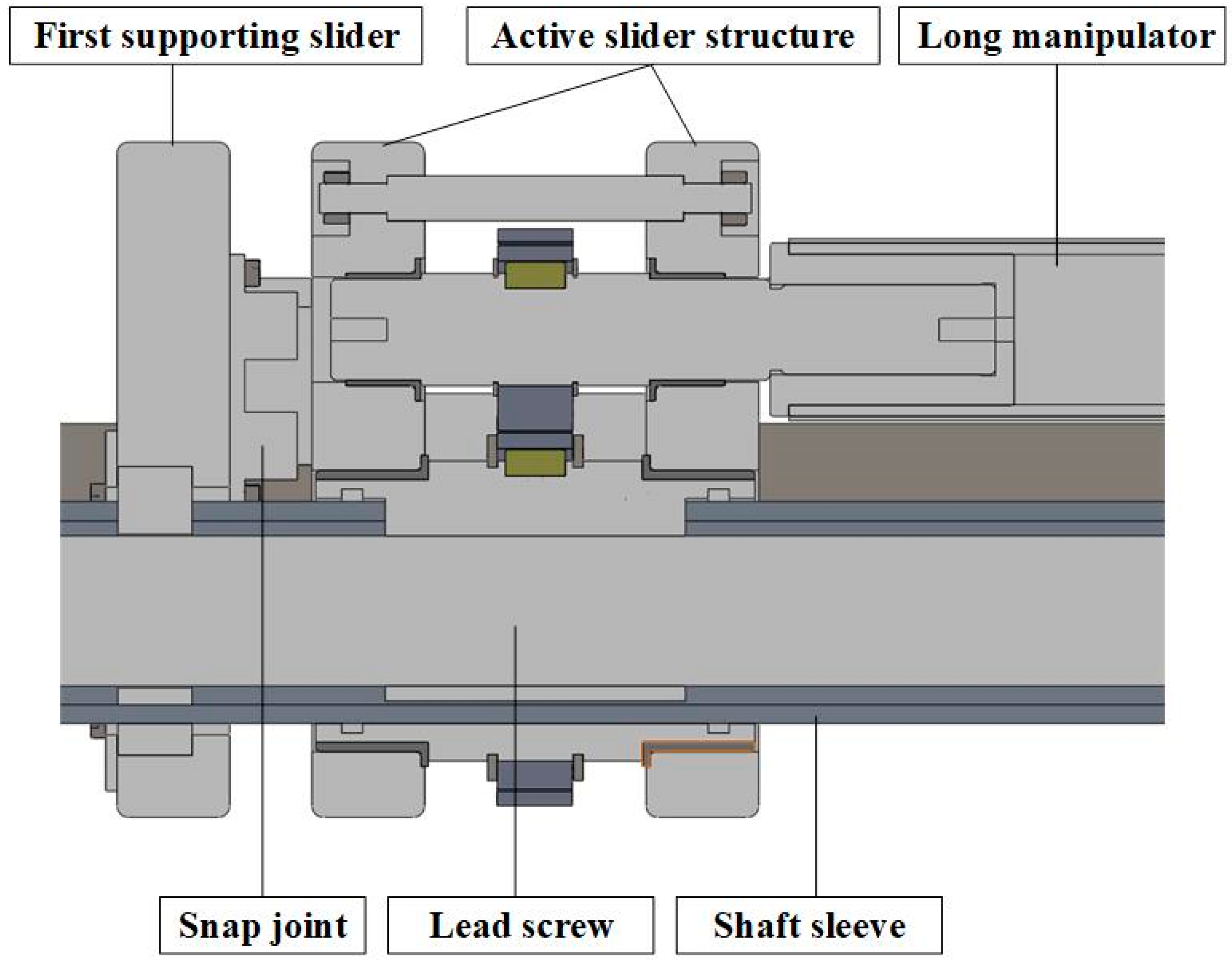
Figure 2, the device mainly consists of one high-pressure cylinder, an active slider, a lead screw, auxiliary supporting slider structure (including two supporting sliders connected by two rods), and a long manipulator for the pressure core and other parts. The auxiliary supporting slider structure is used to support the shaft sleeve and lead screw up to 6 m long and the manipulator up to 3 m long so as to reduce the deformation due to self-gravity and enhance the stability of the device. As
Figure 3 shows, the active slider structure is always moving between two support sliders, and it is connected with the first supporting slider by a snap joint. The auxiliary support slider structure can move with the active slider structure or not depending on the functional requirements. The lead screw is set inside the shaft sleeve.
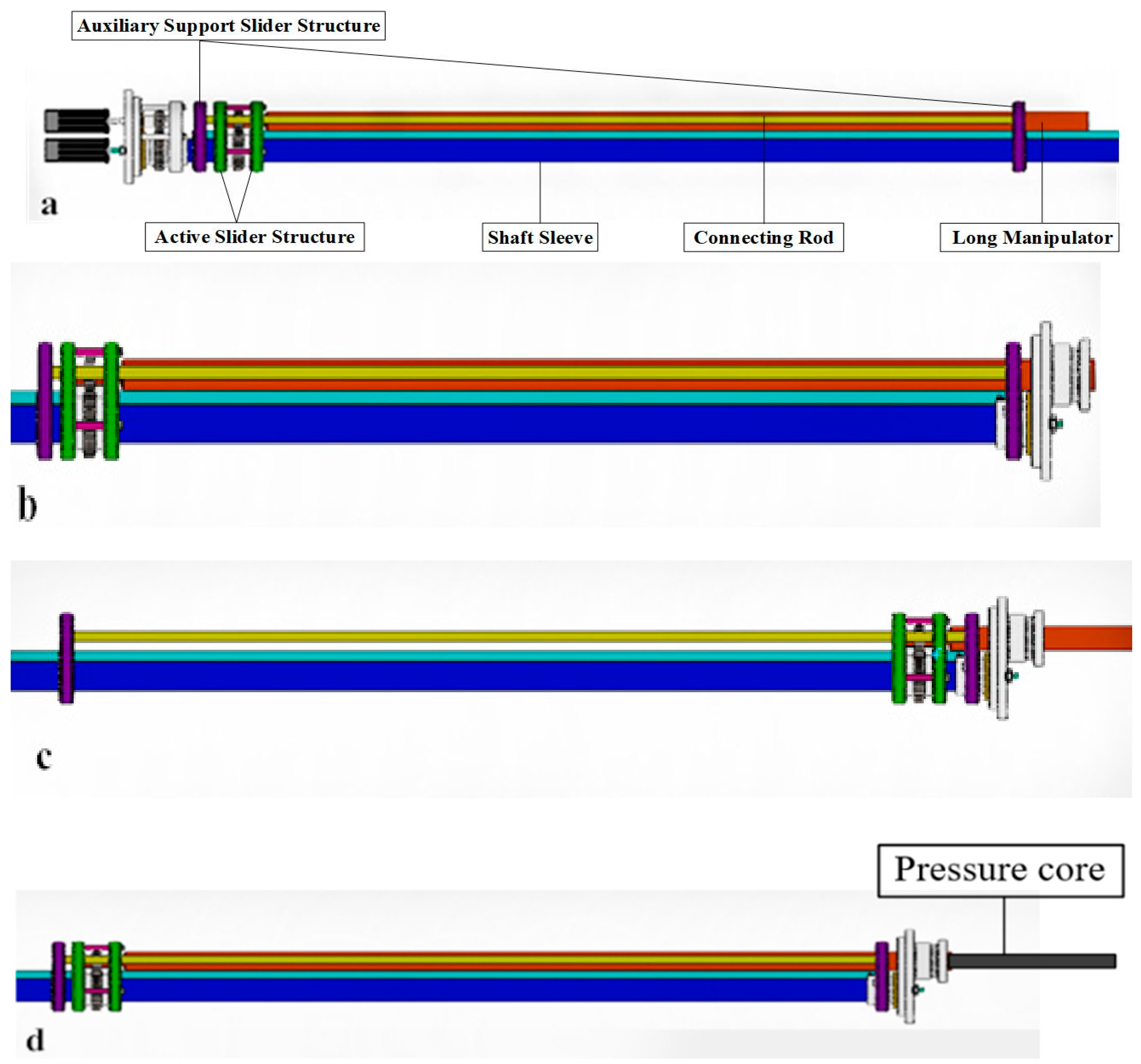
The specific working process is shown in
Figure 4 and proceeds along the following steps.
Figure 4a shows the initial state: The snap joint connects the active slider structure to the left auxiliary support slide.
Figure 4b describes that the electric motor for displacement drives the lead screw to rotate once the drilling pipe filled with pressure core is connected with the analysis and transfer system of natural gas hydrate pressure core. Therefore, the active slider structure and the auxiliary support slider structure move horizontally, meanwhile, the long manipulator fixed on the active slider is driven to grasp the core in the drill pipe through both the cutting device and the test device.
Figure 4c demonstrates that active slider structure would be separated from the left auxiliary supporting slider when the right auxiliary supporting slider moves to the far right. Moreover, the active slider structure would grasp the pressure core in the drilling pipe by moving with the long manipulator. After that, the electric motor rotates reversely to make the active slider structure move in the reverse direction, pulling the pressure core into the testing and cutting device.
Figure 4d represents the electric motor for driving the rotation of the shaft sleeve, until the pressure core reaches the testing device, thus driving both gears on the external shaft sleeve and the gear of the long manipulator. At the same time, the electric motor for displacement also drives the lead screw to rotate and to make sure that the long manipulator with the pressure core only rotates but has no displacement. After finishing testing and cutting the pressure core, the active slider structure moves the far left and connects with the left auxiliary supporting slider by a snap joint again.
Because the entire work process is in a closed pressure cylinder, which prevents either visual inspection or manual intervention, this device can not only make the pressure core (up to 3 m long) move horizontally stably and precisely, but also make the pressure core rotate on its axis stably and precisely in order to complete the testing and cutting of the pressure core under certain situations. The driving device can reduce the jitter of the pressure core during the transferring process to maintain the pressure core in situ pressure and temperature conditions to the maximum extent, which is significant for scientists to understand the intrinsic properties of natural gas hydrate. This device has two major advantages. On the one hand, the length of both the whole system and the lead screw can be reduced significantly. On the other hand, the lead screw is still long enough to require a supporting slider inside the high-pressure cylinder to reduce excessive deformation under its own gravity at up to 6 m long.
3. Research on Driving Device
The lead screw has the advantages of high precision, reversibility, and high efficiency, and is widely used in servo feed systems of CNC machine tools.
In consideration of the maximum length of the pressure core, the length of both the testing device and the cutting device is designed to be about 3 m, meaning that the whole device is at least 6 m length to fully test and cut the pressure core. Moreover, the diameter of the lead screw and spline shaft is so limited by the radial size of the high-pressure cylinder that it should be 30 mm, causing a very large aspect ratio. The lead screw is a low-rigidity component, so it is easy to generate radial deformation, vibration, and noise under the action of external force. If the excitation frequency is close to the resonance frequency of the lead screw, the system may resonate, directly affecting the operation of the mechanism [
12]. Choi et al. verified the correctness of the theoretical analysis by modal analysis and by working vibration measurement of the lead screw feed system [
13]. Therefore, it is vital to analyze the dynamic characteristics of the lead screw, and it is essential to simulate and analyze the whole moving process of this device by software.
In this paper, the modal analysis of the lead screw used in the device is carried out, which includes two kinds of structures: with and without auxiliary support siders. Since the natural frequency of the lead screw is different when the slider is at different positions [
14], the modal analysis is performed at different positions of the slider and the auxiliary support slider to study the effect of support slider on structural stability.
3.1. Finite Element Modeling
Modal analysis is a basic numerical method for calculating the structural vibration characteristics which cover both natural frequencies and modes, which is the most basic kinetic analysis and the basis for other dynamic analyses. The designers can confirm the natural frequency and mode shape of the structure by the modal analysis to avoid resonance during the process of structural design [
15].
The process of finite element modal analysis consists of two parts. Firstly, the modal model of the system is constructed, and then the numerical analysis is carried out.
The free vibration system equation is:
where
is the mass matrix,
is damping matrix,
is stiffness matrix,
is node displacement vector,
is node velocity vector,
is node acceleration vector, and
is the external load vector.
The damping can be ignored, for the damping of the structure has little influence on the frequency and mode of the modal. The un-damped free vibration system equation of the system is:
The form of transforming Equation (2) into displacement vector is:
Take the derivative of Equation (3), and Equation (4) can be obtained:
Bring Equations (3) and (4) into Equation (2) to obtain the characteristic equation of the system, Equation (5):
in order to establish for Equation (5), the determinant of the matrix must be equal to zero, and the characteristic Equation (6) is as follows:
The eigenvalue is obtained by solving the Equation (6). The square root of the eigenvalue is the natural frequency of the system. The natural frequency is substituted into the characteristic Equation (5), and the obtained amplitude matrix [X] is the modal vector.
3.2. Analysis Results
As for the modal analysis, there is a difference in the effect of each mode on the deformation of the structure. Generally speaking, the first 5–10 mode has a dominant impact on the deformation of the structure. On the contrary, the higher-order mode is more complex than the first 5–10 mode, and the influence on the deformation is less than that of the first 5–10 mode [
16]. In the modal analysis of the lead screw, the high order mode has little influence on the structural vibration. When the mode order is higher, the natural frequency of the lead screw is far away from its resonance frequency, and the vibration mode generated is more complex, which does not play a leading role in the analysis of dynamic characteristics of the structure, therefore the dynamic characteristics analysis only extracts the first six orders to analyze the structure’s vibration mode.
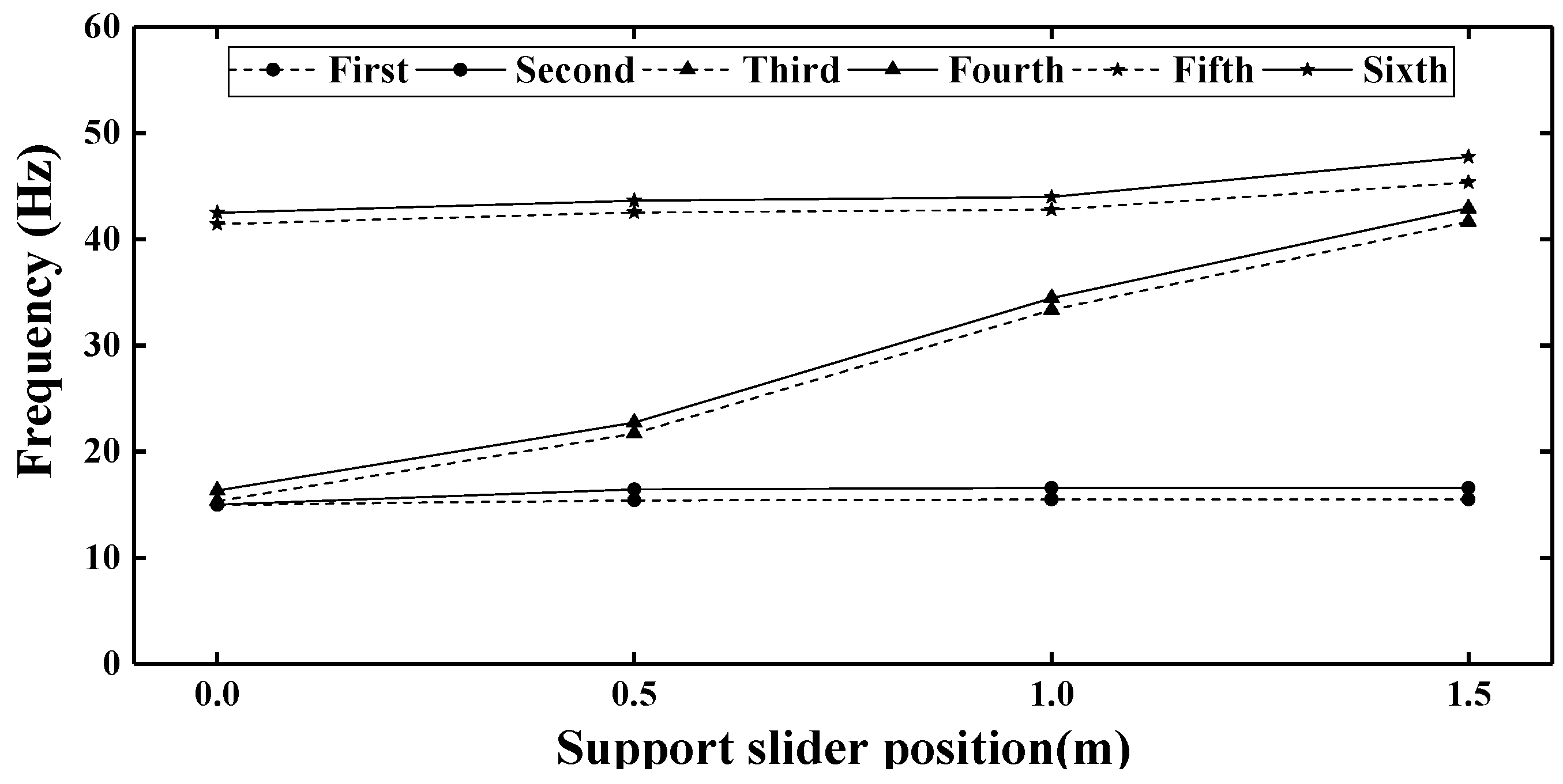
Firstly, as for the lead screw without the auxiliary supporting slider structure, the first six order natural frequency of the lead screw would change with the movement of the slider. In order to study the influence of the position of the active slider, the modal analysis is carried on when the slider is located at the initial, 0.5, 1.0, 1.5, 2.0, 2.5, and 3.0 m position of the lead screw, respectively, and the results of the natural frequency analysis in different positions are shown in
Figure 5.
Secondly, with regard to the lead screw without the auxiliary supporting slider structure, the first six order natural frequency of the lead screw would change with the movement of the support slider. In order to study the influence of the position of the support slider on the natural frequency of the lead screw, the modal analysis is carried on respectively when the nut is located at the initial, 0.5, 1.0, and 1.5 m position of the lead screw, and the results of the natural frequency analysis in different positions are shown in
Figure 6.
The above analysis results show that the position of the slider has an obvious influence on the dynamic characteristics of the lead screw. The natural frequency would increase with the increase of the distance between the slider and the end, which is at its maximum when the slider is located at the middle position (1.5 m) of the lead screw. According to
Figure 6, this is only obvious for the third and fourth natural frequency. There is almost no change for the first and second natural frequencies, and only a very moderate increase for the fifth and sixth. Additionally, the natural frequency of the lead screw with the support slider is larger than that without the support slider.
If the actual speed of the lead screw is near or equal to the critical speed, the resonance may occur, and the whole device can be destroyed severely. Hence it should be noted that it is a necessary way to compare the actual working speed with critical rotating speed by the first-order natural frequency conversion. The conversion formula is given by:
where
is critical speed of the lead screw and
is the natural frequency of the lead screw.
Table 1 and
Table 2 show the different critical rotating speed obtained by calculating according to each first-order natural frequency of the lead screw on the basis of the results of the simulation analysis. The minimum critical rotating speed (239.44 r/min) at the initial place is near to the actual speed of the lead screw, and resonance may have occurred. During the actual transferring process, it would lead to large jitter, which may destroy the original physical and chemical properties, and the geological structure of the pressure core. On the contrary, as
Table 2 shows, with the movement of the support slider, the natural frequency of the lead screw would increase from the initial location to the middle location, in other words, the overall rigidity would increase. The actual rotating speed of the lead screw is far less than the minimum critical speed. As a consequence, the resonance of the lead screw with the supporting sliders cannot be excited at the working rpm range. During the actual transferring process, it would lead to less jitter, which can maintain the pressure core in situ to the maximum extent.
4. Experiment and Test Result Analysis
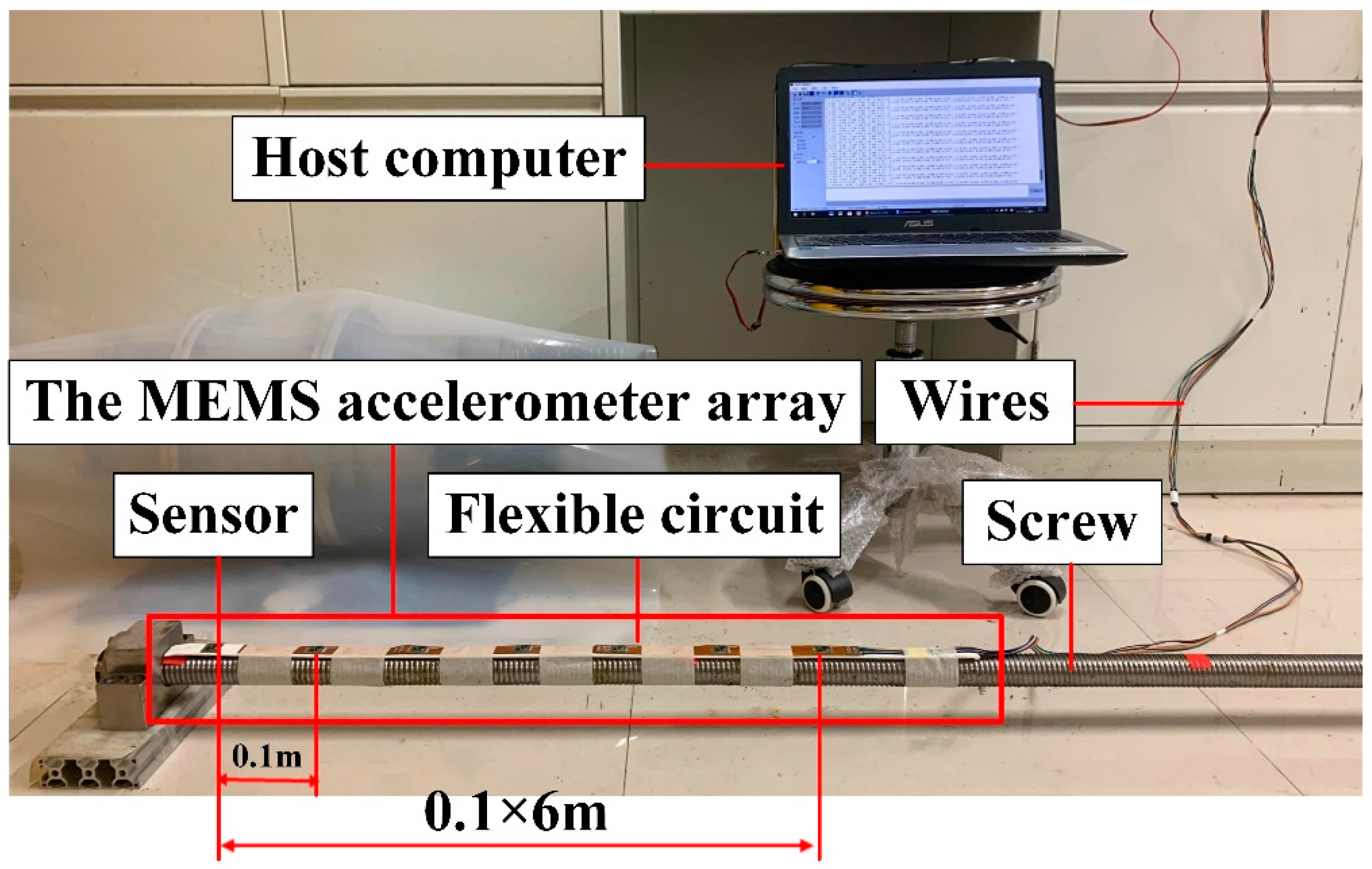
4.1. Testing Device—The Micro-Electro-Mechanical Systems (MEMS) Accelerometer Array
The lead screw is a low-rigidity component. If the amount of radial deformation is too large during the working process, it will directly affect the operation of the mechanism. Therefore, a reliable detecting device is required to detect the amount of radial deformation to verify the reliability of the structure. In view of the characteristic of small size, lightweight, low cost, low power consumption and high reliability, the MEMS 9-axis sensor is proposed to be applied to the radial deformation of the lead screw [
17]. In order to test the radial deformation of the lead screw with or without the support slider, a Micro-Electro-Mechanical Systems (MEMS) accelerometer array was used. The MEMS accelerometer array consists of several gravity-acceleration sensing units that are protected and positioned by the flexible circuit board and elastic steel tape, and all the units are connected to an IIC-communication bus [
18]. By sensing the three-axis tilt angles, the direction and magnitude of the displacement for a measurement unit can be calculated, then the overall displacement of the array is calculated as the difference in the displacements from the initial values. In the process of two-dimensional curve reconstruction from angle to displacement, the arc mode has a better effect [
19].
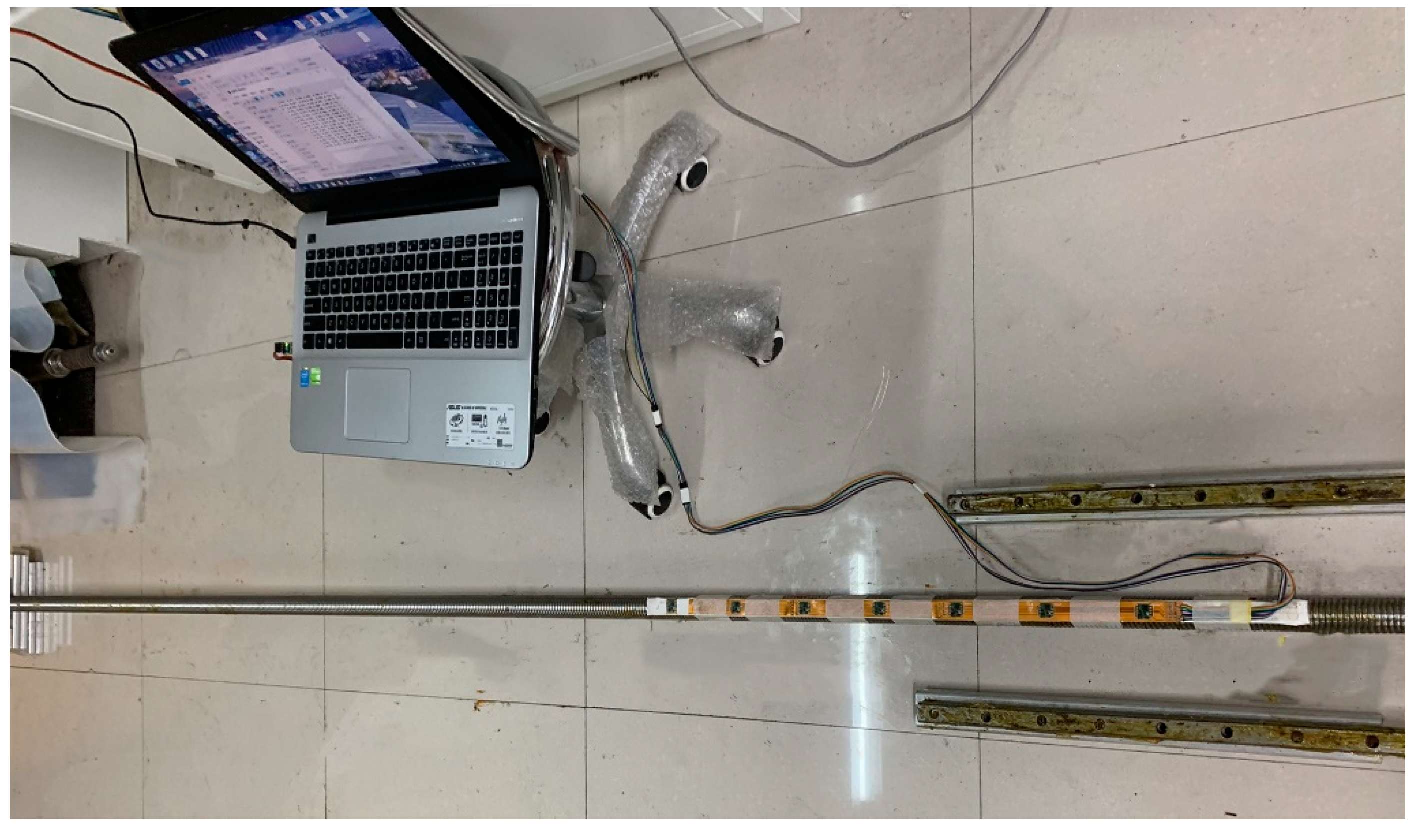
As shown in
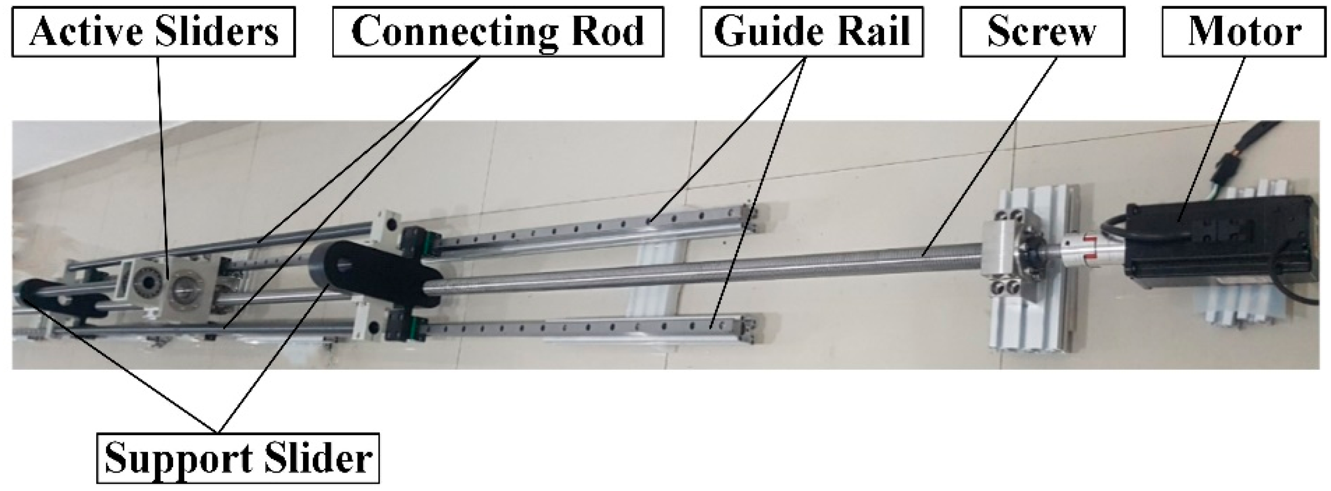
Figure 7, the experimental model is designed and produced to verify the operability and stability of the device.
4.2. Testing Process
As shown in
Figure 8, the MEMS accelerometer array has seven sensors and every two sensors are separated by 100 mm. Therefore, only 600 mm of the length of the lead screw can be detected during a single test.
In the static state, the first sensor of the MEMS accelerometer array is placed at the beginning of the lead screw, and this position is used as a reference point to obtain the amount of radial deformation of other positions relative to the standard point. After testing, the position of the MEMS accelerometer array is changed, and the first sensor is placed at a position 600 mm away from the beginning of the lead screw, which is regarded as another reference point to obtain the radial deformation amount of other positions relative to this position. Therefore, the actual radial deformation amount at 700–1200 mm is the sum of deformation detected and the actual deformation at the 600 mm position. In the same way, the radial deformation of other positions is obtained. Due to the symmetry of the lead screw, only the radial deformation amount of the lead screw at the position 0–3000 mm was tested without support, while the radial deformation amount of the lead screw at the position 0–1500 mm was measured with support. As shown in
Figure 9, the radial deformation amount of the lead screw (2.4–3.0 m position of the lead screw) is detected successively at different positions.
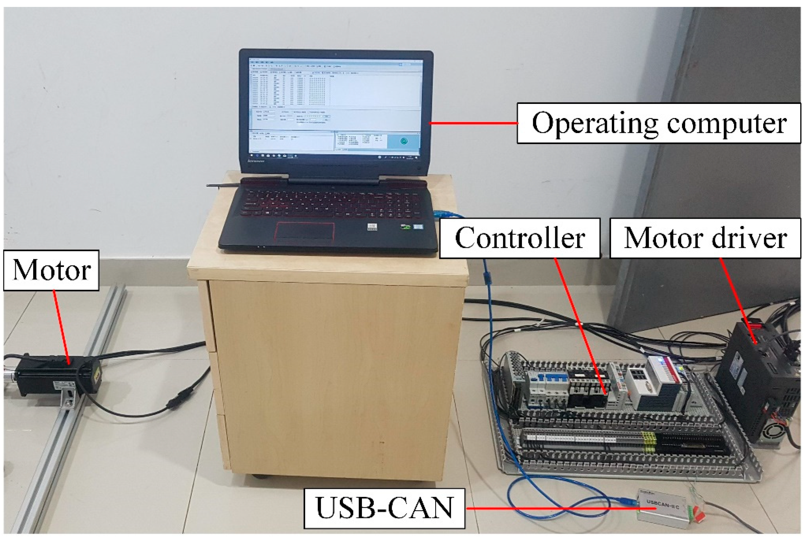
In the rotating state, the testing rotating speed is 100 r/min to prevent the lead screw without the support slider from resonance. The maximum deformation of the lead screw was tested at different positions. The testing method is the same as that in the static state. The motor driving system is shown in
Figure 10.
4.3. The Analysis of Testing Results
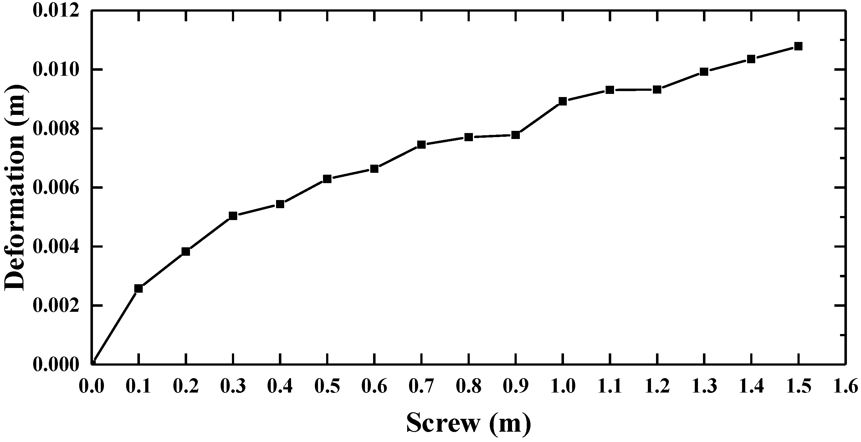
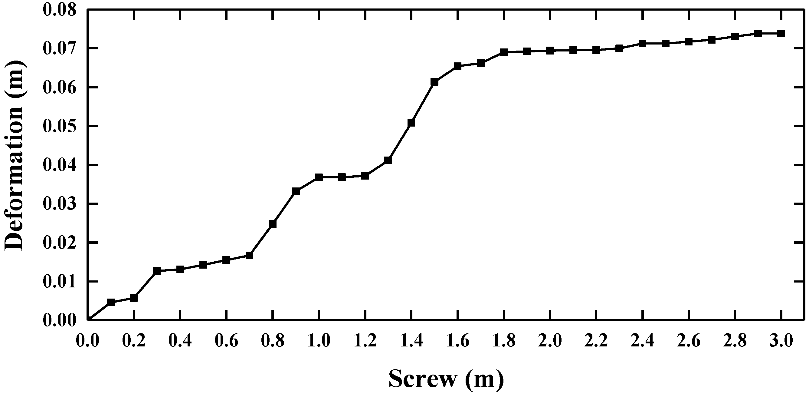
After a series of experiments, the radial deformation amount of the lead screw at the position 0–3000 mm was obtained without a support slider and the radial deformation amount of the lead screw at the position 0–1500 mm was obtained with a support slider in the static state. The data collected by the MEMS accelerometer array is processed by MATLAB software, and the deformation diagram of the lead screw can be obtained as
Figure 11 and
Figure 12 show. We can derive that the deformation of the lead screw would increase as the axial distance of the lead screw increases. The radial maximum deformation of the lead screw without the support slider is 73.8 mm, and the radial maximum deformation of the lead screw with the support slider is 10.8 mm. The testing results indicate the support slider can reduce the deformation of the lead screw to a large extent.
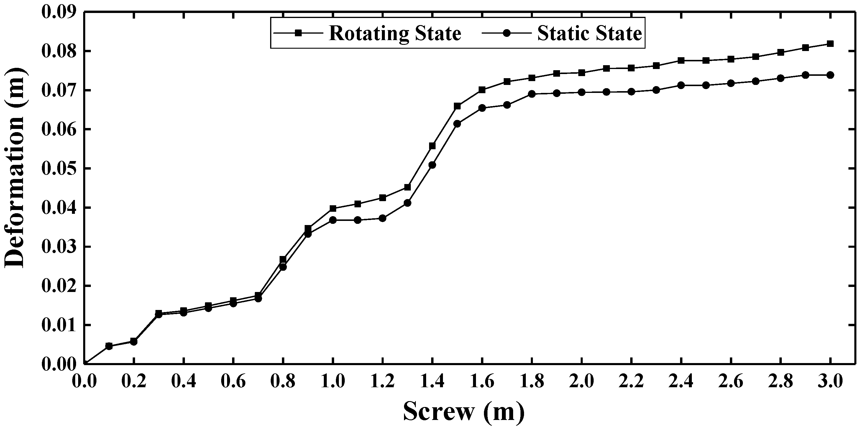
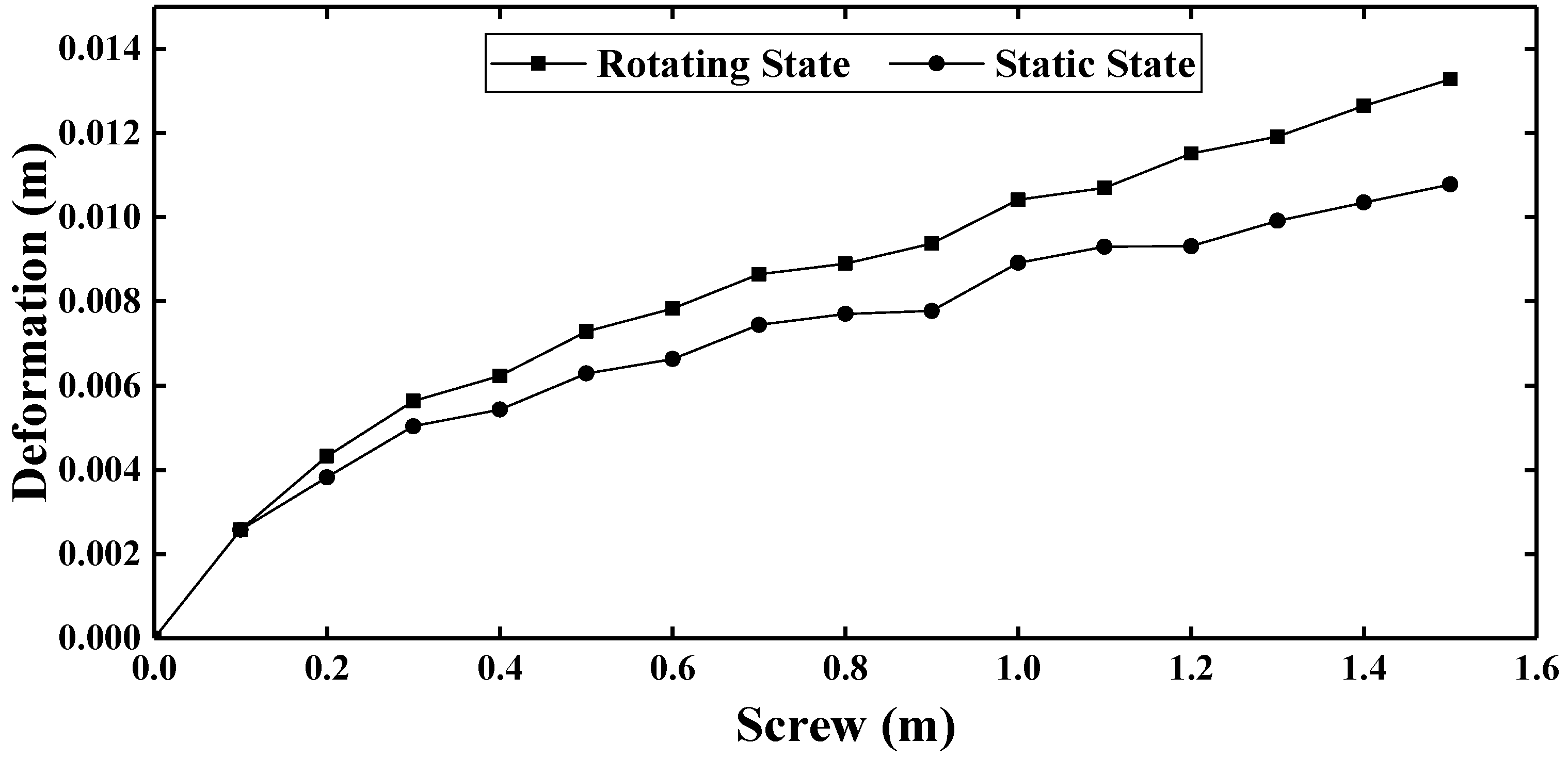
After the rotating experiment, the maximum radial deformation amount of the lead screw at the position 0–3000 mm was obtained without a support slider and the maximum radial deformation amount of the lead screw at the position 0–1500 mm was obtained with a support slider. Next, the data collected by the MEMS accelerometer array is processed by MATLAB software, and the deformation diagram of the lead screw can be obtained, as
Figure 13 and
Figure 14 show. According to
Figure 13 and
Figure 14, we can know that the deformation of the lead screw in the rotating state is larger than that in the static state, since the lead screw is affected by gravity in the static state, but the lead screw is affected by gravitational and centrifugal force in the rotating state [
20]. Moreover, the results confirm the qualitative conclusion that support sliders can reduce the deformation of the lead screw to a large extent. During the actual transferring process, it would lead to less jitter, maintaining the pressure core in situ conditions to the maximum extent.
5. Summary and Conclusions
In the study, a new approach is proposed for transferring a pressure core. The modal analysis of the lead screw is a numerical technique for calculating the vibration characteristics of this device, which can help designers to determine the natural frequency and mode shape of the structure, and can be used in order to avoid any resonance frequency in the structural design. Additionally, we suggest that the MEMS accelerometer array is used to test the deformation of the lead screw in both the static and rotating states for the first time. However, it should be noted that the MEMS accelerometer array only consists of seven sensors to test the deformation, and this study has only examined the deformation of the screw under specific rotating speeds. Additionally, based on the finite element analysis and experiments, this paper draws the following conclusions:
A. A new method for transferring pressure core.
The driving device is an essential part of the analysis and transfer system of natural gas hydrate pressure cores, which provides the mechanism and infrastructure whereby pressure cores up to 3 m in length can be transferred from the coring tool into a measurement chamber, nondestructively analyzed, then transferred into customized pressure chambers for transport or further analysis. Because the whole transferring process is under low temperature (2–4 °C) and high pressure (up to 300 bar), it is of great significance to maintaining the original structure and properties of natural gas hydrate.
B. The modal analysis for the lead screw.
The results of the analysis show that the natural frequency would increase with the increase of the distance between the slider and end, which is at its maximum when the slider is located at the middle position of the lead screw. Furthermore, the natural frequencies of the lead screw with the support slider are larger than those without the support slider.
C. The deformation of the lead screw.
The Micro-Electro-Mechanical Systems (MEMS) accelerometer array was used to test the radial deformation of the lead screw with or without the support slider. The experimental results confirm that the support slider can reduce the radial deformation of the lead screw in both the static and rotating state. Besides, the deformation of the lead screw in the rotating state is larger than that in the static state, since the lead screw is affected by gravity in the static state, but the lead screw is affected by both gravitational and centrifugal forces in the rotating state. We believe that the support slider can reduce the jitter of this device to increase the stability of this device, which can maintain the pressure core in situ and improve the accuracy of examination to the maximum extent.
Author Contributions
Conceptualization, Z.R., J.C. and Q.G.; Data curation, Q.G., P.Z. and K.H.; Formal Analysis, Z.R.; Funding Acquisition, J.C.; Methodology, Z.R., J.C., and Q.G.; Project administration, J.C., B.X. and X.G.; Resources, B.X. and X.G.; Software, Z.R. and K.H.; Supervision, Q.G., P.Z. and K.H.; Validation, J.C.; Visualization, P.Z. and K.H.; Writing-Original Draft Preparation, Z.R.; Writing-Review & Editing, Z.R. All authors have read and agreed to the published version of the manuscript.
Funding
This research was funded by the National Key R&D Program of China, grant number 2017YFC0307503; the Fundamental research Funds for the Central Universities; the Conservation Science and Technology Program of Administration of Cultural Heritage, Zhejiang Province, grant number 2016010; and Marine experimental science and technology innovation service platform of Zhejiang Province, China.
Acknowledgments
The study based on the projects named “Research and Application on Subsea Drilling and Shipborne Detection Technology for Natural Gas Hydrate”, which is derived from the “National Key R&D Program of China (grant No. 2017YFC0307503)” supporting by the Ministry of Science and Technology of the People’s Republic of China; “the Fundamental research Funds for the Central Universities”; “Conservation Science and Technology Program of Administration of Cultural Heritage, Zhejiang Province, (grant No. 2016010)”; “Marine experimental science and technology innovation service platform of Zhejiang Province, China.” I would like to express my gratitude to all those who have helped me during the writing of this thesis.
Conflicts of Interest
The authors declare no conflict of interest.
References
- Licence, P. Clathrate Hydrates of Natural Gases, 3rd ed.; CRC Press: Oxfordshire, UK, 2007; 752p. [Google Scholar]
- Max, M.D. Natural Gas Hydrate in Oceanic and Permafrost Environment; Kluwer Academic Publishers: Dordrecht, The Netherlands, 2003. [Google Scholar]
- Lee, J.Y.; Jung, J.W.; Lee, M.H.; Bahk, J.-J.; Choi, J.; Ryu, B.-J.; Schultheiss, P. Pressure core based study of gas hydrates in the Ulleung Basin and implication for geomechanical controls on gas hydrate occurrence. Mar. Pet. Geol. 2013, 47, 85–98. [Google Scholar] [CrossRef]
- Yang, S.; Liang, J.; Lei, Y.; Gong, Y.; Xu, H.; Wang, H.; Lu, J.; Holland, M.; Schultheiss, P.J.; Wei, J.; et al. GMGS4 gas hydrate drilling expedition in the South China sea. Fire Ice Methane Hydrate Newsl. 2017, 17, 1–5. [Google Scholar]
- Dickens, G.R.; Schroeder, D.; Hinrichs, K.U. The Pressure Core Sampler on ODP Leg 201: General Operations and Gas Release, F. 2003. Available online: http://www-odp.tamu.edu/publications/201_IR/chap_03/c3_.htm (accessed on 15 April 2019).
- Schultheiss, P.J.; Weaver, P.P.E. Multi-Sensor Logging for Science and Industry. Available online: https://ieeexplore.ieee.org/document/607652 (accessed on 10 May 2019).
- Priest, J.A.; Druce, M.; Roberts, J.; Schultheiss, P.; Nakatsuka, Y.; Suzuki, K. PCATS Triaxial: A new geotechnical apparatus for characterizing pressure cores from the Nankai Trough, Japan. Mar. Pet. Geol. 2015, 66, 460–470. [Google Scholar] [CrossRef]
- Zhang, H.; Yang, S.; Wu, N.; Schultheiss, P.; Rose, K.; Butler, H.; Humphrey, G.; GMGS-1 Science Team. Successful and surprising results for china’s first gas hydrate drilling. Fire Ice 2007, 7, 6–9. [Google Scholar]
- Schultheiss, P.J.; Francis, T.J.G.; Holland, M.; Roberts, J.A.; Amann, H.; Parkes, R.J.; Martin, D.; Rothfuss, M.; Tyunder, F.; Jackson, P.D.; et al. Pressure coring, logging and subsampling with the HYACINTH system. Geol. Soc. Lond. Spec. Publ. 2006, 267, 151–163. [Google Scholar] [CrossRef]
- Matsumoto, R.; Ryu, B.-J.; Lee, S.-R.; Lin, S.; Wu, S.; Sain, K.; Pecher, I.; Riedel, M. Occurrence and exploration of gas hydrate in the marginal seas and continental margin of the Asia and Oceania region. Mar. Pet. Geol. 2011, 28, 1751–1767. [Google Scholar] [CrossRef]
- Jin, Y.; Konno, Y.; Yoneda, J.; Kida, M.; Nagao, J. In situ methane hydrate morphology investigation: natural gas hydrate-bearing sediment recovered from the eastern Nankai trough area. Energy Fuels 2016, 30, 5547–5554. [Google Scholar] [CrossRef]
- Zhang, Y.W.; Zhang, W.M. Modal analysis of ball screw drive system by finite element method. Key Eng. Mater. 2011, 1076, 285–288. [Google Scholar] [CrossRef]
- Xu, X.R.; Song, X.C.; Jiang, H.K.; Li, Y.F. Finite element modal analysis of ball screws linear guide feed unit. Appl. Mech. Mater. 2013, 2755, 67–71. [Google Scholar] [CrossRef]
- Xiao, Y.J.; Ren, Q.G. Study and Analysis of Reliability and Stability Design of the Rail Screw Mechanism Transmission. J. Mech. Transm. 2013, 37, 106–109. [Google Scholar]
- Choi, Y.H.; Cha, S.M.; Hong, J.H.; Choi, J.H. A study on the vibration analysis of a ball screw feed drive system. Mater. Sci. Forum 2004, 506, 149–154. [Google Scholar] [CrossRef]
- Gallina, P. About the stability of non-conservative undamped systems. J. Sound Vib. 2013, 262, 977–988. [Google Scholar] [CrossRef]
- Xu, C.; Chen, J.; Zhu, H.; Liu, H. Experimental Study on Seafloor Vertical Deformation Monitoring Based on MEMS Accelerometer Array. In Proceedings of the 28th International Ocean and Polar Engineering Conference, Sapporo, Japan, 10–15 June 2018. [Google Scholar]
- Xu, C.; Chen, J.; Zhu, H.; Zhang, P.; Ren, Z.; Zhu, H.; Lin, Y. Design and laboratory testing of a MEMS accelerometer array for subsidence monitoring. Rev. Sci. Instrum. 2018, 89. [Google Scholar] [CrossRef] [PubMed]
- Xu, C.; Chen, J.; Zhu, H.; Liu, H.; Lin, Y. Experimental Research on Seafloor Mapping and Vertical Deformation Monitoring Using MEMS nine-axis Sensor Tapes. IEEE J. Ocean. Eng. 2018, 99, 1–12. [Google Scholar] [CrossRef]
- Fu, K.K.; Zhang, C.; Ye, S.J.; Zheng, B.L.; Xu, Z.Z. Analysis on Radial Deflection of High-Speed Shaft under Gravitational and Centrifugal Force. J. Shantou Univ. 2014, 29, 68–72. [Google Scholar]
© 2020 by the authors. Licensee MDPI, Basel, Switzerland. This article is an open access article distributed under the terms and conditions of the Creative Commons Attribution (CC BY) license (http://creativecommons.org/licenses/by/4.0/).


 ,
, 


