Article

Characterization of Effective In-Plane Electrical Resistivity of a Gas Diffusion Layer in Polymer Electrolyte Membrane Fuel Cells through Freeze–Thaw Thermal Cycles

Department of Mechanical Engineering, Inha University, Incheon 22212, Korea
*
Author to whom correspondence should be addressed.
Energies 2020, 13(1), 145; https://doi.org/10.3390/en13010145
Submission received: 22 November 2019 / Revised: 16 December 2019 / Accepted: 25 December 2019 / Published: 27 December 2019
(This article belongs to the Special Issue Polymer Electrolyte Membrane Fuel Cells 2019)

Abstract

:
The electrical property of gas diffusion layers (GDLs) plays a significant role in influencing the overall performance of polymer electrolyte membrane fuel cells (PEMFCs). The electrical degradation performance of GDLs has not been reported sufficiently. Understanding the electrical degradation characteristics of GDLs is vital to better fuel cell performance, higher efficiency, and longer service time. This paper investigated the effective in-plane electrical resistivity of a commercial GDL by considering environmental and assembly conditions similar to those in use for the operation of PEMFCs. The effective in-plane electrical resistivity of the GDL, subjected to a series of freeze–thaw thermal cycles, was characterized to study its progressive electrical degradation with thermal cycles. Experimental results indicated that, under low compressive loads, the effective in-plane electrical resistivity of the commercial GDL showed weak anisotropy, and was greatly influenced by the transformation of carbon fiber connection in the porous layer. In particular, the thermal aging treatment on the GDL through the first 100 freeze–thaw cycles contributed a lot to its in-plane electrical degradation performance.

Graphical Abstract

1. Introduction

Over the past several decades, electrochemical energy conversion and storage systems have attracted increasing attention due to many benefits like utilization of renewable energy, greenhouse gas reduction, and extensive application in the market. Even though some progress has been achieved in energy conversion technologies, tremendous efforts are still required on the aspects of lower cost, improvement of the overall performance, and higher efficiency of energy devices [1]. Electrochemical energy conversion and storage systems typically include batteries, fuel cells, and supercapacitors [2]. It has been reported that polymer electrolytes undertake the important roles in influencing the electrochemical characteristics of supercapacitors [3] and lithium batteries [4,5,6]. Depending on the electrolyte types, fuel cells are generally classified into six types [7,8,9]: direct methanol fuel cells (DMFCs), alkaline fuel cells (AFCs), phosphoric acid fuel cells (PAFCs), molten carbonate fuel cells (MCFCs), solid oxide fuel cells (SOFCs), and polymer electrolyte membrane fuel cells (PEMFCs). As one of the most potential fuel cell candidates, PEMFCs have achieved more and more attention owing to their high power density, environmental friendliness, wider applications, etc. Low manufacturing costs, higher power density, and more excellent electrical performance of PMEFCs are tireless pursuits of researchers and manufacturers.
PEMFCs could convert chemical energy into electricity by releasing water and heat, directly and efficiently. One unit of PEMFCs is assembled with a polymer electrolyte membrane (PEM), two catalyst layers (CLs), two gas diffusion layers (GDLs), and two bipolar plates (BPPs) under specific assembling loads [10]. Considering the real configuration of PEMFCs, GDLs are sandwiched together with CLs and BPPs (with gas channels on the surface). Thus, GDLs have to endure inhomogeneous loads under such a complicated configuration [11]. What is more, GDLs are obliged to take the responsibility of collecting and transporting current under severe mechanical pressure. Studying the inherent electrical characteristics of GDLs by considering the impacts of mechanical loads could not only achieve more accurate electrical properties, but also provide guidance for the electrical performance improvement of PEMFCs.
In general, electrical properties of GDLs are described by electrical resistance (such as sheet, bulk, and contact resistance) [11,12,13,14,15], electrical resistivity (like area, bulk, and contact resistivity) [16,17], electrical conductivity [18,19,20,21,22,23,24,25], and so on. Research on GDLs’ electrical performance is mostly based on two types: carbon paper (with non-woven carbon fibers) and carbon cloth (with woven carbon fibers) [26,27]. Both of the GDL types have layered structures in common: a porous layer (also known as the transport layer, substrate, or micro-porous layer) made of carbon paper or carbon cloth; and a coating layer made of carbon powder and polytetrafluoroethylene (PTFE, an electrical insulator) [28]. Although higher PTFE loading can properly improve the mechanical properties of carbon fibers, it also causes higher electrical resistance [29] and electronic resistivity [30]. Moreover, increasing PTFE loading results in the increase of GDLs’ contact resistivity; however, it barely affects their bulk resistivity [31]. The addition of PTFE content does not significantly influence the in-plane electrical conductivity of GDLs [24,32], but it negatively impacts GDLs’ through-plane electrical conductivity [24]. Thus, it can be concluded that the porous layer in GDLs dominates in determining the in-plane electrical performance. In practice, the anisotropy in the electrical conductivity of GDLs depends more on the porous layer than the coating layer due to the conductive materials (such as carbon fibers) used in it [20]. Owing to the random arrangement of carbon fibers in the porous layer, GDLs’ through and in-plane electrical properties have been proved anisotropic [25] and sensitive to mechanical loads [12,17,24]. Although the application of mechanical pressure on GDLs could lead to structural failure of carbon fibers (like fracture, breakage, and crack), it also results in better connectivity of carbon fiber networks [33,34]. Thus, GDLs’ electrical conductivity could be improved with increasing the clamping stress to some extent. Additionally, some researchers built numerical models to predict the effective electrical conductivity of GDLs [35,36]. It is well known that the durability or service time is also a vital evaluation index to assess the performance of PEMFCs. When fuel cells are working, heat and water are continuously produced and exhausted. Obviously, GDLs do not only suffer serious clamping pressure, but also experience periodic and changeable environmental conditions; both of which affect the electrical performance directly and remarkably. To date, although comprehensive studies of GDLs’ electrical behavior regarding the effects of component materials as well as mechanical loads have been published, studies related to its electrical properties by combining the effects of mechanical loads and environmental conditions are very few. This paper fills the gap.
As a polymer thin film, the thickness of most commercial GDLs is usually among 100–400 μm [37,38]. Accordingly, the electrical performance of GDLs could be typically stated by in-plane resistivity which is the material’s inherent characteristic, not determined by geometry dimensions of materials [39]. This paper investigated the effective in-plane electrical resistivity of a commercial GDL by considering the impacts of compressive loads and environmental conditions. Significantly, the effective in-plane electrical resistivity of the commercial GDL through different degrees of freeze–thaw thermal aging treatment was also characterized to study its progressive electrical degradation performance. Moreover, the status of carbon fiber connection in the porous layer was observed through microstructural images, which was used to explain its in-plane electrical characteristics.

2. Experimental Sections

2.1. Material

This paper investigated the effective in-plane electrical resistivity of a commercial GDL based on a carbon paper (JNT 30-A1, Hwasung, Korea) with the original thickness of 320 ± 20 μm and geometrical dimension of 300 mm × 210 mm × (320 ± 20) μm, as described in Figure 1a. Given the anisotropic characteristics of GDLs, the orientation was defined on the original GDL sheet. In this article, the in-plane direction is located in the X-Y plane, as seen in Figure 1a. The microstructure of the pristine GDL in the coating layer and the porous layer was observed via images which were captured by scanning electron microscopy (SEM; Hitachi SU-8010, Tokyo, Japan), as shown in parts b and c of Figure 1, respectively. The coating layer is made of PTFE without any crack or mechanical damage and the porous layer is composed of carbon fibers which are in quite good alignments with each other. SEM images of GDLs with other types can be found in [28,40]. Besides, specimens (with the X × Y size of 40 mm × 5 mm and 5 mm × 40 mm) were separately tailored from the commercial GDL sheet for their in-plane electrical resistance measurements.

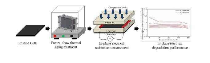
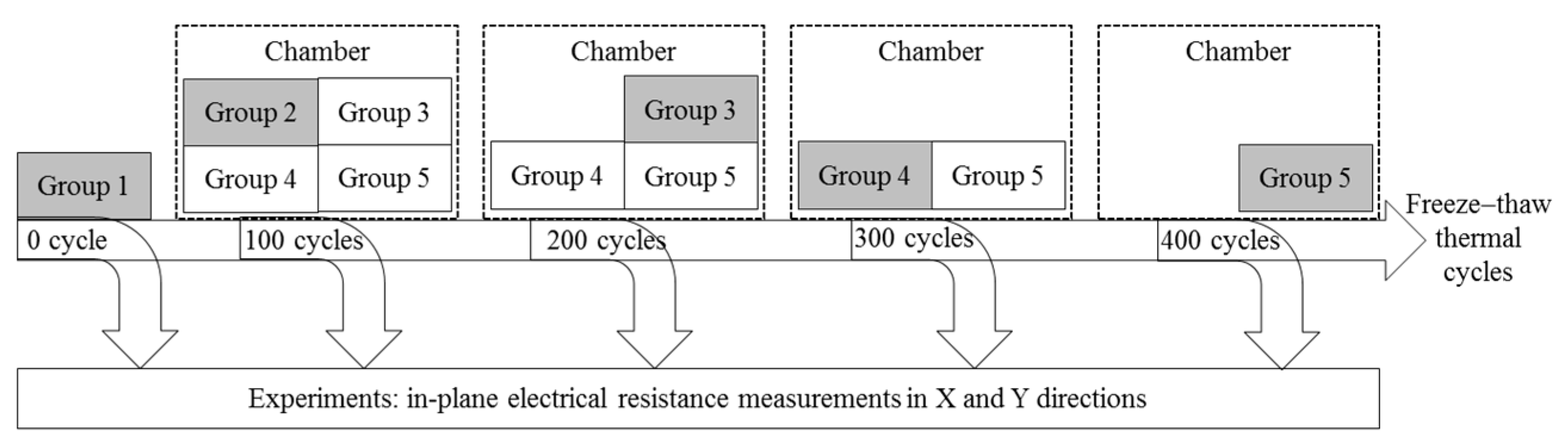
2.2. Freeze–Thaw Thermal Treatment

In general, the whole service time of fuel cells depends on many factors such as types, size, and usage. During the operation of PEMFCs, the internal temperature and humidity change rapidly and dramatically. Without a doubt, the mechanical and physical properties of GDLs would be affected directly and heavily under such serious environmental circumstances. This research investigated the effective in-plane electrical resistivity degradation performance of a commercial GDL by considering its working environmental conditions and clamping status. One complete freeze–thaw thermal cycle (around 3 h) was employed to imitate the ambient operating conditions of GDLs in fuel cells (temperature: −20 °C to 80 °C; humidity: 100%). A detailed design of the freeze–thaw thermal cycle can be found in [41]. The freeze–thaw thermal aging treatment on specimens was performed in a temperature and humidity control chamber (TEMI 300, Seoul, Korea). According to the general service time of fuel cells, the overall freeze–thaw thermal treatment time was set at 1200 h. Before subjecting the specimens to the thermal aging treatment, they were pretreated by clamping each sheet of the commercial GDL within two plates under a certain pressure to get close to real clamping conditions in PEMFCs. To study the progressive change of the in-plane electrical resistivity degradation of the commercial GDL with the increase in freeze–thaw thermal cycles, five representative groups were tested, as illustrated in Figure 2. After each group went through a certain number of thermal cycles, the specimens were taken out of the chamber machine and disassembled to be prepared for the in-plane electrical resistance measurement.

2.3. Test Methods

In-plane electrical properties of GDLs could be measured by many approaches, such as van der Pauw method [42], Montgomery method [43], four-wire Kelvin method [44], improved four-point measurement in compliance with ASTM C611 [27,45], two-probe measurements [46], and square four-point probe arrangement method [12]; however, at present, there is no standard testing method for measuring the in-plane electrical resistivity of GDLs. In most cases, researchers designed or modified measurement methods to meet the specific experimental requirements. This research adopted a test method (as shown in Figure 3) [39] to measure the in-plane electrical resistance of GDLs under a series of compressive loads. The compressive loads were performed by a material tester (BS-205, Osan, Korea). In this study, the compressive loads were applied on GDLs with a lower stress range (less than 3 MPa) by considering the contact pressure in PEMFCs [47]. Furthermore, the present test method was carried out based on the assumption that electrodes have no effects on the mechanical deformation of GDLs. Both the upper jig and the lower jig in Figure 3b were made of insulating materials with high mechanical strength to achieve highly accurate experimental results. When measuring the in-plane electrical resistance of GDLs, five specimens were tested for each experiment.
The effective in-plane electrical resistivity of anisotropic materials ( ρ i ) is calculated by Equation (1) [48]:
ρ i = C i R i t f ,
where C i is the correction factor in direction i; t f is the effective thickness of the long and thin-film specimen; R i is the measured resistance in direction i. Besides, C i in two perpendicular X and Y directions [49] can be stated as follows:
C x 8 π sinh [ π ( y x ) ] ,
C y 8 π sinh [ π ( x y ) ] ,
where x and y are the in-plane dimensional sizes of an isotropic equivalent specimen transformed from an anisotropic specimen by complying with Wasscher’s transformation [50], as illustrated in Figure 4.
According to Wasscher’s transformation rules, the isotropic electrical resistivity ρ is described by:
ρ 3 = ρ x ρ y ρ z .
In addition, the anisotropic electrical resistivity and the dimensional size of the anisotropic specimen have the relationship as:
L i = L i ρ i ρ ,
where L i is the dimensional size of the isotropic equivalent specimen (as shown in Figure 4), L i = x , y , or z ; and L i is the dimensional size of the anisotropic specimen, L i = x , y , or z . Combining Equations (4) and (5), the in-plane electrical resistivity ρ x and ρ y in X and Y directions [49] can be stated as:
ρ x ρ y = ( x x y y ) 2 ,
ρ x ρ y = C x R x t f = C y R y t f .
In addition, x y [49] in Equation (6) can be approximately expressed by:
x y 1 2 [ 1 π ln R x R y + [ 1 π ln R x R y ] 2 + 4 ] ,
where R x and R y are the measured in-plane electrical resistance of the anisotropic specimen in X and Y directions, respectively. As a result, the effective in-plane electrical resistivity of the long and thin-film specimen in X and Y directions can be rewritten by Equations (8) and (9). The abovementioned calculation details can be used to determine the effective in-plane electrical resistivity of GDLs.
ρ x = π 8 ( x y ) ( y x ) sinh [ π ( y x ) ] R x t f
ρ y = π 8 ( y x ) ( x y ) sinh [ π ( x y ) ] R y t f .

3. Results and Discussion

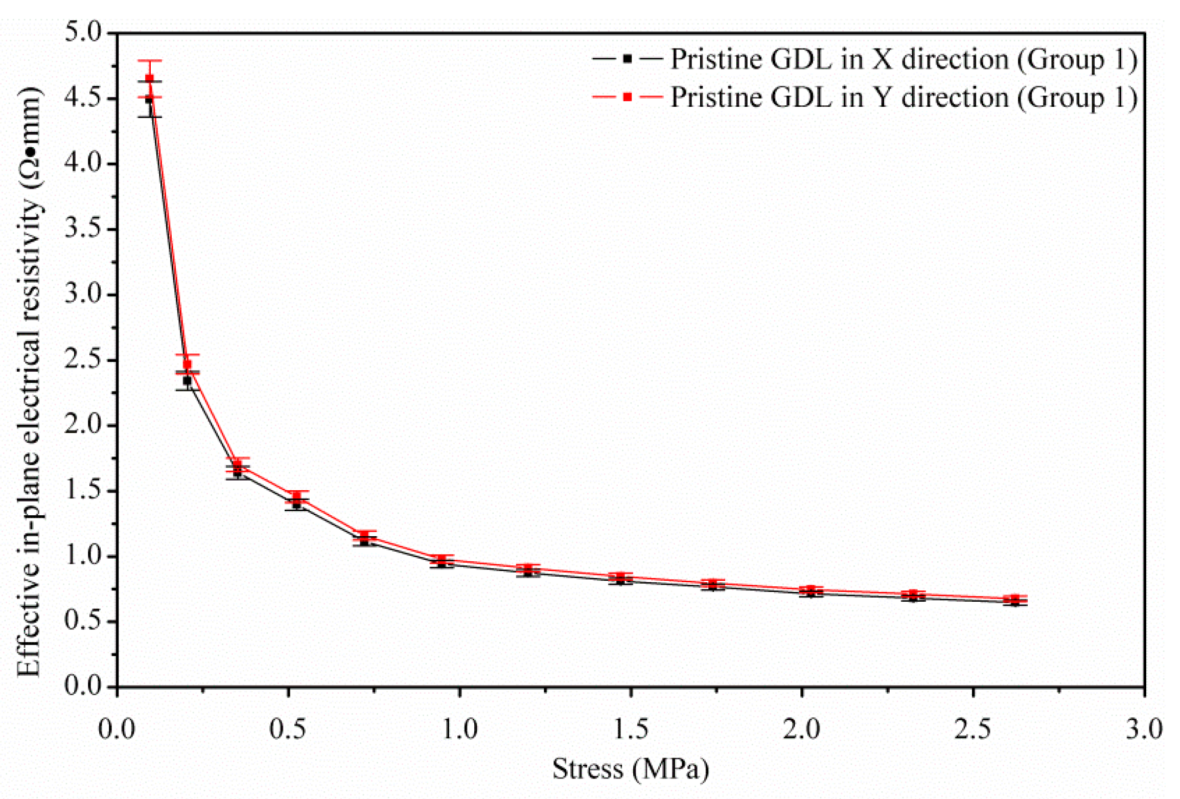
3.1. Effective In-Plane Electrical Resistivity of Pristine GDLs

The thickness and in-plane electrical resistance of fresh GDLs were recorded as the stress of the applied compressive loads increased. The test results are shown in Figure 5. With the increase in compressive stress, the thickness gradually decreased and became thinner and thinner (see Figure 5a), which is in accordance with the research results in [24,36]. As seen in Figure 5b, the measured electrical resistance in X direction was a little larger than that in Y direction. It meant that the in-plane electrical resistance of the commercial GDL showed weak anisotropic characteristics similar to that observed in [20,21,51]. In some publications [14,27], the in-plane electrical properties of GDLs were treated as isotropic to simplify the model and calculation.
Following the calculation methods in Section 2.3, the relationship between the effective in-plane electrical resistivity vs. compressive loads of fresh GDLs was achieved (see Figure 6) by utilizing the experimental data in Figure 5, which exhibited the same trend as resistance vs. stress. In both X and Y directions, the effective in-plane electrical resistivity dropped dramatically at the initial stage of applying loads; after 1 MPa, it remained almost stable around 1.25 Ω·mm. Although the effective in-plane electrical resistivity of fresh GDLs displayed slight anisotropy, the anisotropic phenomenon became increasingly weak with the increase in loads. The dramatic decrease phenomenon occurring in Figure 6 could be explained by the schematics in Figure 7.
Anisotropy in the in-plane electrical resistivity of GDLs with the carbon paper is greatly determined by carbon fiber orientation in the porous layer, not in the coating layer. The significant decreasing trend in the in-plane electrical resistance (or resistivity) of fresh GDLs (as observed in Figure 5b and Figure 6) was mainly due to the good connectivity among carbon fibers. Connectivity between carbon fibers changed as compressive loads increased, especially at the starting stage of applying loads. Based on the observation of a representative SEM image of carbon fibers in the porous layer after compressive loads, the extreme decrease in Figure 5b and Figure 6 can be interpreted by two typical types of carbon fiber connection, as illustrated in Figure 7b,c. At low to medium compressive loads, the contact between carbon fibers changed considerably. Firstly, the cross-section of carbon fibers deformed from a circle to an ellipse (see Figure 7b) without any structural failure, which made the contact surface between fibers to enlarge. It meant that the effective current flow area increased. Then, with a further increase in the compressive pressure, some fibers broke into several parts (see Figure 7c) to respond to mechanical loads. At the same time, more fibers came into contact in a smaller matrix volume as the gaps between adjacent layers of fibers decreased with increasing compressive loads [52,53]. Overall, with increasing compressive pressure from very low to medium values, a large number of carbon fibers were connected effectively and closely, which resulted in the reduction of in-plane electrical resistance (or resistivity) of GDLs (see Figure 5b and Figure 6). Similar reports can be found in [24]. When the applied load increases from medium to higher values (in this study, load over 1 MPa), the in-plane electrical resistance (or resistivity) of fresh GDLs does not change practically. This is because, at high loads, almost all the non-touching carbon fibers of the adjacent layers have already come in contact with each other where any further increase cannot bring more fibers in contact. In addition, at high loads, more carbon fibers may break, which reduces the number of contact points while increasing the contact area a little. As such, there is no significant reduction in GDLs’ in-plane electrical resistivity when increasing from medium to high loads. Although, it is indeed difficult to explain the stable phenomenon in the microstructural scale, it can be described by the thickness of GDLs [17,36] under compressive loads. The thickness of GDLs is almost a constant once the compressive load is up to a certain threshold value [54], which may indicate that the connection between fibers could reach a stable state in accordance with the almost unchanged in-plane electrical resistivity.

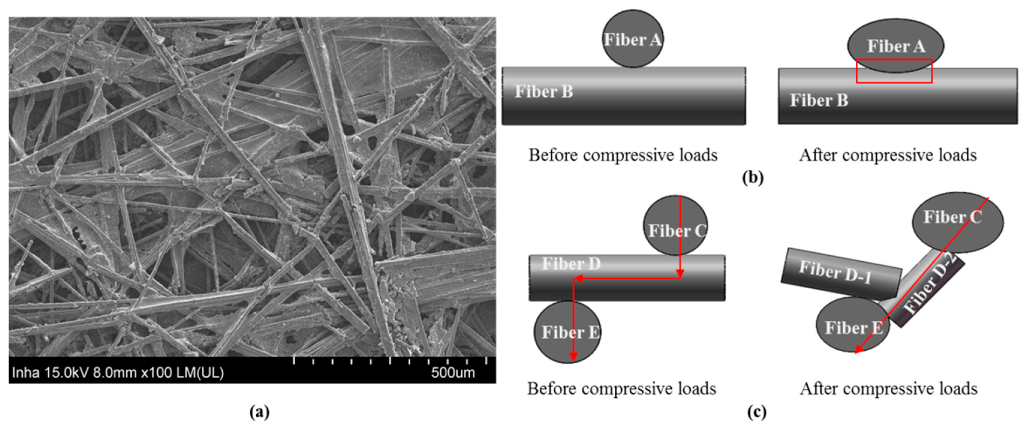
3.2. Effective In-Plane Electrical Resistivity of Aged GDLs

Besides measuring the in-plane electrical resistance of pristine GDLs (group 1), other groups that experienced different repetitive freeze–thaw thermal cycles were tested, as well. The test results are shown in Figure 8. The effective in-plane electrical resistivity of all the groups in spite of fresh or aged GDLs showed the same tendency with the increase in compressive loads. At the initial stage of applying loads (less than 1 MPa), the in-plane electrical resistivity of fresh GDLs was a little higher than that of aged groups. In the case of compressive stress beyond 1 MPa, there was no big difference between fresh and aged GDLs. Among aged groups, the effective in-plane electrical resistivity almost remained the same no matter how many thermal cycles went. In order to clearly observe the effects of thermal aging treatment on the in-plane electrical characteristics of GDLs, the relationship between the effective in-plane electrical resistivity and thermal cycles under different compressive loads was studied (see Figure 9b). Weak anisotropy in in-plane electrical resistivity was observed, regardless of fresh or aged GDLs.
As discussed previously, the change of GDLs’ thickness coincided with their in-plane electrical resistivity. In practice, the thickness variation comes down to the transformation of carbon fiber connection. It can be seen that the thickness of aged GDLs almost remained a constant after the first 100 freeze–thaw thermal cycle treatments (see Figure 9a). If the compressive loads are over 1 MPa, the thickness of fresh and aged GDLs is measured with the same value. Compared to pristine GDLs, the thickness degradation of aged GDLs is caused by the assembly force from assembling procedure in fuel cells [55] and frost-heaving force generated from freeze-thaw thermal cycles [56]. Both the assembly load and frost-heaving force play a critical role in changing carbon fiber connection under a small external force, which results in the thickness reduction between fresh and aged GDLs. If the external load is large enough (like beyond 1 MPa), the thickness decrease could be determined by external loads, not assembly or frost-heaving force. The detailed thickness degradation performance of GDLs can be found in [41]. Thus, it is easy to understand how the in-plane electrical resistivity of GDLs is influenced by freeze–thaw thermal treatments. In conclusion, the first 100 thermal cycles treatment on GDLs plays a significant role in affecting their in-plane electrical degradation performance under small external loads.

4. Conclusions

This research experimentally investigated the effective in-plane electrical resistivity of a commercial GDL. By considering GDLs’ assembly conditions and fuel cell operation environment, a freeze–thaw thermophysical cycle was repeatedly performed to prepare GDL specimens to make them experience environmental conditions similar to real operating conditions in PEMFCs. The in-plane electrical resistance and thickness of GDLs subjected to various numbers of thermal aging cycles were measured to monitor their progressive degradation. The results showed that the effective in-plane electrical resistivity of both pristine and aged GDLs exhibited weak anisotropy, which may mainly come from the transformation of carbon fiber alignments and connectivity characteristics in the porous layer. Particularly, the freeze–thaw thermal treatment on GDLs through the first 100 cycles contributed a lot to their in-plane electrical resistivity degradation under a small external load.
In conclusion, GDLs suffered three loading types such as external loads (like compressive stress), clamping force (from assembly configuration), and frost-heaving force (produced by thermal aging treatment) that resulted in a reduction of their thickness. In practice, the thickness decrease could come down to the compact connectivity of carbon fibers, resulting in a larger effective in-plane electrical conductivity or a smaller in-plane resistivity.

Author Contributions

Conceptualization, Y.C. and C.C.; Methodology, Y.C. and C.J.; Validation, Y.C., C.J., and C.C.; Formal Analysis, Y.C.; Data Curation, Y.C. and C.J.; Writing—Original Draft Preparation, Y.C.; Writing—Review and Editing, Y.C. and C.C.; Supervision, C.C. All authors have read and agreed to the published version of the manuscript.

Funding

This research received no external funding.

Acknowledgments

This research was supported by the Inha University.

Conflicts of Interest

The authors declare no conflicts of interest.

References

  1. Wei, H.; Cui, D.; Ma, J.; Chu, L.; Zhao, X.; Song, H.; Liu, H.; Liu, T.; Wang, N.; Guo, Z. Energy conversion technologies towards self-powered electrochemical energy storage systems: The state of the art and perspectives. J. Mater. Chem. A 2017, 5, 1873–1894. [Google Scholar] [CrossRef]
  2. Luo, B.; Ye, D.; Wang, L. Recent progress on integrated energy conversion and storage systems. Adv. Sci. 2017, 4, 1700104. [Google Scholar] [CrossRef] [PubMed] [Green Version]
  3. Zhao, X.; Yang, Y.; Wu, J.; Tan, Y.; Liu, Y.; Kong, L.; Kang, L.; Ran, F. A polymer-supported electrolyte-affinity hybrid membrane and modification of the amphiphilic block copolymer for use as a super-high flexible and high-performance supercapacitor. Sustain. Energy Fuels 2017, 1, 1074–1081. [Google Scholar] [CrossRef]
  4. Piana, G.; Bella, F.; Geobaldo, F.; Meligrana, G.; Gerbaldi, C. PEO/LAGP hybrid solid polymer electrolytes for ambient temperature lithium batteries by solvent-free, “one pot” preparation. J. Energy Storage 2019, 26, 100947. [Google Scholar] [CrossRef]
  5. Falco, M.; Castro, L.; Nair, J.R.; Bella, F.; Bardé, F.; Meligrana, G.; Gerbaldi, C. Uv-cross-linked composite polymer electrolyte for high-rate, ambient temperature lithium batteries. ACS Appl. Energy Mater. 2019, 2, 1600–1607. [Google Scholar] [CrossRef]
  6. Falco, M.; Simari, C.; Ferrara, C.; Nair, J.R.; Meligrana, G.; Bella, F.; Nicotera, I.; Mustarelli, P.; Winter, M.; Gerbaldi, C. Understanding the effect of uv-induced cross-linking on the physico-chemical properties of highly performing peo/litfsi-based polymer electrolytes. Langmuir 2019, 35, 8210–8219. [Google Scholar]
  7. Inci, M.; Türksoy, Ö. Review of fuel cells to grid interface: Configurations, technical challenges and trends. J. Clean. Prod. 2019, 213, 1353–1370. [Google Scholar] [CrossRef]
  8. Stamatakis, E.; Yiotis, A.; Giannissi, S.; Tolias, I.; Stubos, A. Modeling and simulation supporting the application of fuel cell & hydrogen technologies. J. Comput. Sci. 2018, 27, 10–20. [Google Scholar]
  9. Hart, D.; Lewis, J.; Lehner, F.; Klippenstein, M.; Rose, R. The Fuel Cell Industry Review 2017. e4tech. Available online: http://www.fuelcellindustryreview.com/archive/TheFuelCellIndustryReview2017.pdf (accessed on 22 November 2019).
  10. Dafalla, A.M.; Jiang, F. Stresses and their impacts on proton exchange membrane fuel cells: A review. Int. J. Hydrogen Energy 2018, 43, 2327–2348. [Google Scholar] [CrossRef]
  11. Vikram, A.; Chowdhury, P.R.; Phillips, R.K.; Hoorfar, M. Measurement of effective bulk and contact resistance of gas diffusion layer under inhomogeneous compression—Part I: Electrical conductivity. J. Power Sources 2016, 320, 274–285. [Google Scholar] [CrossRef]
  12. Todd, D.; Bennett, S.; Mérida, W. Anisotropic electrical resistance of proton exchange membrane fuel cell transport layers as a function of cyclic strain. Int. J. Hydrogen Energy 2016, 41, 6029–6035. [Google Scholar] [CrossRef]
  13. El Oualid, S.; Lachat, R.; Candusso, D.; Meyer, Y. Characterization process to measure the electrical contact resistance of gas diffusion layers under mechanical static compressive loads. Int. J. Hydrogen Energy 2017, 42, 23920–23931. [Google Scholar] [CrossRef] [Green Version]
  14. Zhou, T.; Liu, H. Effects of the electrical resistances of the gdl in a pem fuel cell. J. Power Sources 2006, 161, 444–453. [Google Scholar] [CrossRef]
  15. Tanaka, S.; Shudo, T. Experimental and numerical modeling study of the electrical resistance of gas diffusion layer-less polymer electrolyte membrane fuel cells. J. Power Sources 2015, 278, 382–395. [Google Scholar] [CrossRef]
  16. Bapat, C.; Thynell, S. Effect of anisotropic electrical resistivity of gas diffusion layers (gdls) on current density and temperature distribution in a polymer electrolyte membrane (pem) fuel cell. J. Power Sources 2008, 185, 428–432. [Google Scholar] [CrossRef]
  17. Todd, D.; Schwager, M.; Mérida, W. Three-dimensional anisotropic electrical resistivity of pem fuel cell transport layers as functions of compressive strain. J. Electrochem. Soc. 2015, 162, F265–F272. [Google Scholar] [CrossRef] [Green Version]
  18. Aydin, Ö.; Zedda, M.; Zamel, N. Challenges associated with measuring the intrinsic electrical conductivity of carbon paper diffusion media. Fuel Cells 2015, 15, 537–544. [Google Scholar] [CrossRef]
  19. Morris, D.R.; Gostick, J.T. Determination of the in-plane components of the electrical conductivity tensor in pem fuel cell gas diffusion layers. Electrochim. Acta 2012, 85, 665–673. [Google Scholar] [CrossRef] [Green Version]
  20. Ismail, M.; Damjanovic, T.; Ingham, D.B.; Pourkashanian, M.; Westwood, A. Effect of polytetrafluoroethylene-treatment and microporous layer-coating on the electrical conductivity of gas diffusion layers used in proton exchange membrane fuel cells. J. Power Sources 2010, 195, 2700–2708. [Google Scholar] [CrossRef]
  21. Ismail, M.; Hughes, K.; Ingham, D.B.; Ma, L.; Pourkashanian, M. Effects of anisotropic permeability and electrical conductivity of gas diffusion layers on the performance of proton exchange membrane fuel cells. Appl. Energy 2012, 95, 50–63. [Google Scholar] [CrossRef]
  22. Cai, J.; Wei, W.; Hu, X.; Wood, D.A. Electrical conductivity models in saturated porous media: A review. Earth-Sci. Rev. 2017, 171, 419–433. [Google Scholar] [CrossRef]
  23. Omrani, R.; Shabani, B. Gas diffusion layers in fuel cells and electrolysers: A novel semi-empirical model to predict electrical conductivity of sintered metal fibres. Energies 2019, 12, 855. [Google Scholar] [CrossRef] [Green Version]
  24. Sadeghifar, H. In-plane and through-plane electrical conductivities and contact resistances of a mercedes-benz catalyst-coated membrane, gas diffusion and micro-porous layers and a ballard graphite bipolar plate: Impact of humidity, compressive load and polytetrafluoroethylene. Energy Convers. Manag. 2017, 154, 191–202. [Google Scholar]
  25. Zamel, N.; Li, X.; Shen, J. Numerical estimation of the effective electrical conductivity in carbon paper diffusion media. Appl. Energy 2012, 93, 39–44. [Google Scholar] [CrossRef]
  26. Kim, H.; Lee, Y.-J.; Lee, S.-J.; Chung, Y.-S.; Yoo, Y. Fabrication of carbon papers using polyacrylonitrile fibers as a binder. J. Mater. Sci. 2014, 49, 3831–3838. [Google Scholar] [CrossRef]
  27. Williams, M.V.; Begg, E.; Bonville, L.; Kunz, H.R.; Fenton, J.M. Characterization of gas diffusion layers for pemfc. J. Electrochem. Soc. 2004, 151, A1173–A1180. [Google Scholar] [CrossRef]
  28. Sadeghifar, H.; Djilali, N.; Bahrami, M. Counter-intuitive reduction of thermal contact resistance with porosity: A case study of polymer electrolyte membrane fuel cells. Int. J. Hydrogen Energy 2016, 41, 6833–6841. [Google Scholar] [CrossRef]
  29. Su, H.; Sita, C.; Pasupathi, S. The effect of gas diffusion layer ptfe content on the performance of high temperature proton exchange membrane fuel cell. Int. J. Electrochem. Sci. 2016, 11, 2919–2926. [Google Scholar] [CrossRef]
  30. Lobato, J.; Canizares, P.; Rodrigo, M.; Ruiz-López, C.; Linares, J. Influence of the teflon loading in the gas diffusion layer of pbi-based pem fuel cells. J. Appl. Electrochem. 2008, 38, 793–802. [Google Scholar] [CrossRef]
  31. Ye, D.; Gauthier, E.; Benziger, J.B.; Pan, M. Bulk and contact resistances of gas diffusion layers in proton exchange membrane fuel cells. J. Power Sources 2014, 256, 449–456. [Google Scholar] [CrossRef]
  32. Rohendi, D.; Majlan, E.H.; Mohamad, A.B.; Daud, W.R.W.; Kadhum, A.A.H.; Shyuan, L.K. Effect of ptfe content and sintering temperature on the properties of a fuel cell electrode backing layer. J. Fuel Cell Sci. Technol. 2014, 11, 041003. [Google Scholar] [CrossRef]
  33. Hamour, M.; Grandidier, J.; Ouibrahim, A.; Martemianov, S. Electrical conductivity of pemfc under loading. J. Power Sources 2015, 289, 160–167. [Google Scholar] [CrossRef]
  34. Parikh, N.; Allen, J.; Yassar, R.S. Effect of deformation on electrical properties of carbon fibers used in gas diffusion layer of proton exchange membrane fuel cells. J. Power Sources 2009, 193, 766–768. [Google Scholar] [CrossRef]
  35. Tanaka, S.; Bradfield, W.W.; Legrand, C.; Malan, A.G. Numerical and experimental study of the effects of the electrical resistance and diffusivity under clamping pressure on the performance of a metallic gas-diffusion layer in polymer electrolyte fuel cells. J. Power Sources 2016, 330, 273–284. [Google Scholar] [CrossRef]
  36. Kleemann, J.; Finsterwalder, F.; Tillmetz, W. Characterisation of mechanical behaviour and coupled electrical properties of polymer electrolyte membrane fuel cell gas diffusion layers. J. Power Sources 2009, 190, 92–102. [Google Scholar] [CrossRef]
  37. Lee, J.; Chevalier, S.; Banerjee, R.; Antonacci, P.; Ge, N.; Yip, R.; Kotaka, T.; Tabuchi, Y.; Bazylak, A. Investigating the effects of gas diffusion layer substrate thickness on polymer electrolyte membrane fuel cell performance via synchrotron x-ray radiography. Electrochim. Acta 2017, 236, 161–170. [Google Scholar] [CrossRef]
  38. Abderezzak, B. Introduction to Transfer Phenomena in Pem Fuel Cells, 1st ed.; ISTE Press-Elsevier: London, UK, 2019; pp. 132–144. [Google Scholar]
  39. Matboo Ghorbani, M.; Taherian, R. Methods of measuring electrical properties of material. In Electrical Conductivity in Polymer-Bansed Composites: Experiments, Modelling and Applications, 1st ed.; Taherian, R., Kausar, A., Eds.; William Andrew: New York, NY, USA, 2018; pp. 365–394. [Google Scholar]
  40. Sadeghifar, H.; Djilali, N.; Bahrami, M. Effect of polytetrafluoroethylene (ptfe) and micro porous layer (mpl) on thermal conductivity of fuel cell gas diffusion layers: Modeling and experiments. J. Power Sources 2014, 248, 632–641. [Google Scholar] [CrossRef]
  41. Chen, Y.; Jiang, C.; Cho, C. Effects of freeze⁻thaw thermal cycles on the mechanical degradation of the gas diffusion layer in polymer electrolyte membrane fuel cells. Polymers 2019, 11, 428. [Google Scholar] [CrossRef] [Green Version]
  42. Philips’Gloeilampenfabrieken, O. A method of measuring specific resistivity and hall effect of discs of arbitrary shape. Philips Res. Rep. 1958, 13, 1–9. [Google Scholar]
  43. Montgomery, H.C. Method for measuring electrical resistivity of anisotropic materials. J. Appl. Phys. 1971, 42, 2971–2975. [Google Scholar] [CrossRef]
  44. Jayakumar, A.; Singamneni, S.; Ramos, M.; Al-Jumaily, A.M.; Pethaiah, S.S. Manufacturing the gas diffusion layer for pem fuel cell using a novel 3D printing technique and critical assessment of the challenges encountered. Materials 2017, 10, 796. [Google Scholar] [CrossRef] [Green Version]
  45. Murthy, M. Proton Conducting Membrane Fuel Cells III: Proceedings of the International Symposium; The Electrochemical Society: Pennington, NJ, USA, 2005; pp. 270–286. [Google Scholar]
  46. Li, M.-Y.; Yang, M.; Vargas, E.; Neff, K.; Vanli, A.; Liang, R. Analysis of variance on thickness and electrical conductivity measurements of carbon nanotube thin films. Meas. Sci. Technol. 2016, 27, 095004. [Google Scholar] [CrossRef]
  47. Qiu, D.; Yi, P.; Peng, L.; Lai, X. Study on shape error effect of metallic bipolar plate on the gdl contact pressure distribution in proton exchange membrane fuel cell. Int. J. Hydrogen Energy 2013, 38, 6762–6772. [Google Scholar] [CrossRef]
  48. Smits, F. Measurement of sheet resistivities with the four-point probe. Bell Syst. Tech. J. 1958, 37, 711–718. [Google Scholar] [CrossRef]
  49. dos Santos, C.; de Campos, A.; da Luz, M.S.; White, B.D.; Neumeier, J.J.; de Lima, B.S.; Shigue, C.Y. Procedure for measuring electrical resistivity of anisotropic materials: A revision of the montgomery method. J. Appl. Phys. 2011, 110, 083703. [Google Scholar] [CrossRef]
  50. Wasscher, J. Note on four-point resistivity measurements on anisotropic conductors. Philips Res. Rep. 1961, 16, 301–306. [Google Scholar]
  51. Vielstich, W.; Lamm, A.; Gasteiger, H.A. Handbook of Fuel Cells: Fundamentals Technology and Applications; John Wiley & Sons: New York, NY, USA, 2003; Volume 3, pp. 517–537. [Google Scholar]
  52. Sadeghifar, H.; Djilali, N.; Bahrami, M. A new model for thermal contact resistance between fuel cell gas diffusion layers and bipolar plates. J. Power Sources 2014, 266, 51–59. [Google Scholar] [CrossRef]
  53. Sadeghifar, H.; Bahrami, M.; Djilali, N. A statistically-based thermal conductivity model for fuel cell gas diffusion layers. J. Power Sources 2013, 233, 369–379. [Google Scholar] [CrossRef]
  54. Carral, C.; Mélé, P. A constitutive law to predict the compression of gas diffusion layers. Int. J. Hydrogen Energy 2018, 43, 19721–19729. [Google Scholar] [CrossRef]
  55. Movahedi, M.; Ramiar, A.; Ranjber, A. 3D numerical investigation of clamping pressure effect on the performance of proton exchange membrane fuel cell with interdigitated flow field. Energy 2018, 142, 617–632. [Google Scholar] [CrossRef]
  56. He, S.; Kim, S.H.; Mench, M.M. 1D transient model for frost heave in polymer electrolyte fuel cells II. Parametric study. J. Electrochem. Soc. 2007, 154, B1024–B1033. [Google Scholar] [CrossRef]
Figure 1. (a) Geometrical dimension size of the commercial GDL sheet (JNT 30-A1); (b) SEM image of the coating layer; (c) SEM image of the porous layer.
Energies 13 00145 g001
Figure 2. Group division of GDLs going through different degrees of freeze–thaw thermal treatment.
Energies 13 00145 g002
Figure 3. Schematics of the in-plane electrical resistance measurement of the commercial GDL: (a) Test procedure; (b) test structure.
Energies 13 00145 g003
Figure 4. Wasscher’s transformation of an anisotropic specimen to an isotropic equivalent specimen.
Energies 13 00145 g004
Figure 5. Test data of fresh GDLs: (a) Thickness vs. stress; (b) in-plane electrical resistance vs. stress.
Energies 13 00145 g005
Figure 6. Effective in-plane electrical resistivity vs. stress of pristine GDLs.
Energies 13 00145 g006
Figure 7. Connectivity of carbon fibers in the porous layer: (a) SEM image of the porous layer after compressive loads; (b) schematics of carbon fiber connection without crack; (c) schematics of carbon fiber connection with crack.
Energies 13 00145 g007
Figure 8. Effective in-plane electrical resistance vs. stress curves of pristine and aged GDLs.
Energies 13 00145 g008
Figure 9. Degradation of pristine and aged GDLs: (a) Thickness vs. freeze–thaw thermal cycles; (b) effective in-plane electrical resistivity vs. freeze–thaw thermal cycles.
Energies 13 00145 g009

