1. Introduction
Due to the widespread utilisation of high-grade heat sources in industry and transportation, there has been an increase in waste heat rejected to the environment. Therefore, many technologies have been developed for waste heat recovery applications for a range of scales and heat-grades. Thermoacoustic traveling-wave engines (TATWE) have drawn attention because of their advantages which include no mechanical moving parts, longevity and the use of environmentally friendly gases as working media [
1]. Thermoacoustic engines are capable of converting heat into acoustic power. The acoustic power generated by the TATWE can be used to generate electricity by driving an electromechanical linear alternator or generate cooling by driving a thermoacoustic refrigerator [
2] or a pulse tube cryocooler [
3,
4]. In general, TATWE take the form of an acoustic resonator filled with a gas and containing a thermoacoustic core consisting of a porous medium (stack or regenerator) with heat source and heat sink (i.e., heat exchangers) adjacent to it. The gas in the vicinity of the solid surface of the porous medium undergoes a thermodynamic cycle somewhat similar to the Stirling cycle.
The first TATWE in a looped-tube configuration was presented by Yazaki et al. [
5]. It can be likened in certain respects to a standing-wave thermoacoustic engine because of the two-wavelength loop containing the thermoacoustic core at a specific location. Yazaki et al. [
5] designed and built their air-filled engine to study the spontaneous gas oscillations in a travelling wave setting. The experimental results showed that the travelling wave outperformed the standing wave engines at the same frequency and wavelength. The low efficiency of this engine was discovered to be caused by low acoustic impedance (acoustic impedance is the ratio of oscillating pressure to volume flow rate). Looped-tube TATWE can have more than one thermoacoustic core in the same engine. These so-called multi-stage TATWEs are a solution to a low acoustic impedance and work at low onset temperature [
6,
7]. The multi-stage TATWE can be built either having identical stages each having a power extraction point or a number of geometrically non-identical stages in series and a single alternator in the loop. Although the cross section of the thermoacoustic cores in series increases in the wave propagation direction to reduce acoustic loses [
8,
9], identical stages run at lower acoustic losses as the staged power extraction points allow the device to run without high acoustic power “spots”.
de Blok [
8,
10] built four engines demonstrating the possibility of cascading stages in looped tube TATWE. The engines consisted of four identical stages each having a power extraction point, and they were generating electricity in a range of 18 W to 1.64 kW. Zhang and Chang [
7] studied the onset temperature, mean pressure, type of working medium (gas), hydraulic radius as well as the number of stages in a four-stage engine configuration similar to de Blok’s [
8]. They also investigated replacing one of the engine stages with a refrigerator stage [
11]. The results showed that the device can reach a relative Carnot COP (coefficient of performance) of 28.5% at a cooling temperature of 5 °C. Yang et al. [
12] adopted the four-stage configuration and adapted it by replacing one stage with acoustic compliance acting as acoustic impedance control. The engine design aimed at low-grade temperature. A thermal-to-electric efficiency of 1.51% was achieved at the hot temperature of 120 °C. Yang et al. [
13] developed the engine by adding five acoustic loads. A maximum thermal efficiency achieved was 9.6% at the hot temperature of 195 °C. Li et al. [
14] suggested an upgrade for the system with four identical stages by installing a branch containing a refrigerator stage and a dual linear alternator.
Another multi-stage configuration proposed by Li et al. [
15] was built as three identical stages with linear alternators connected in-line to shift the phase difference. At a mean pressure of 40 bar of helium, each stage of the engine generated 1080 W of acoustic power at 36% total efficiency. Wu et al. [
16] developed the system to generate useful electricity. At 50 bar mean pressure and 650 °C heating temperature, the engine generated 1.57 kW of electricity at thermal-to-electric efficiency of 16.8%. Bi et al. [
17] optimized the acoustic network of the engines and ran it at a higher mean pressure of 60 bar; the engine generated 4.69 kW at 15.6% of thermal-to-electric efficiency.
Linear alternators convert the acoustic power into electricity at high transduction efficiency. The alternators used in thermoacoustic technology must have flexure bearings and gas clearance seals, which require no lubrication, to make them compatible with the low-maintenance requirements of thermoacoustic devices. The main disadvantage is that they are expensive. Hamood et al. [
18] showed that the linear alternator performance improves with increasing the acoustic impedance. It is then advantageous to utilize multi-stage TATWE where high acoustic impedance is favourable for the linear alternator to generate higher electrical power. However, for “self-matched” identical stages they require many expensive linear alternators to run at high acoustic impedance and relatively low acoustic losses—hence finding a way to limit the number of alternators is important. The aim of the current research is to demonstrate a configuration that enables coupling one linear alternator to two power extraction points of two stages that work in pressure antiphase, thus reducing the number of expensive alternators in the system. Here, the effective acoustic field driving the linear alternator is the algebraic sum of the two fields belonging to the two stages.
2. Experimental Apparatus
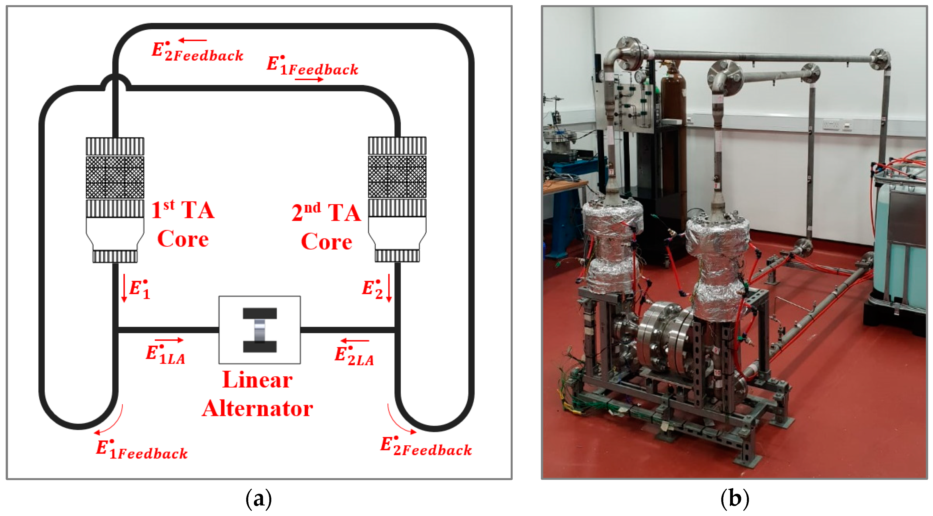
The experimental apparatus consists of two identical engine stages each having a power extraction point, and a linear alternator connected to these two power extraction points. The conceptual design of the electricity generator is shown in
Figure 1a, while
Figure 1b shows a photograph of the actual device. The identical stages generate acoustic waves having similar pressure and volume flow rate amplitudes, but which are out of phase by 180° between the two stages. When these out of phase acoustic fields act upon the alternator, one is “pushing” while the other is “pulling” the piston. Hence, the active acoustic impedance running the alternator is the sum of the two push-pull acoustic fields, and this will increase the power output at a specific acoustic impedance [
18].
The DeltaEC (design environment for low-amplitude thermoacoustic energy conversion) simulation tool was used to simulate the acoustic field and optimize the dimensions of the device components. DeltaEC is a design tool for thermoacoustic applications developed based on the linear thermoacoustic theory [
19]. It enables a continuous optimization process to investigate the dimensions that offer the best performance. After a complex trade-off optimization process which considers the performance and parts’ availability, a successful model was generated.
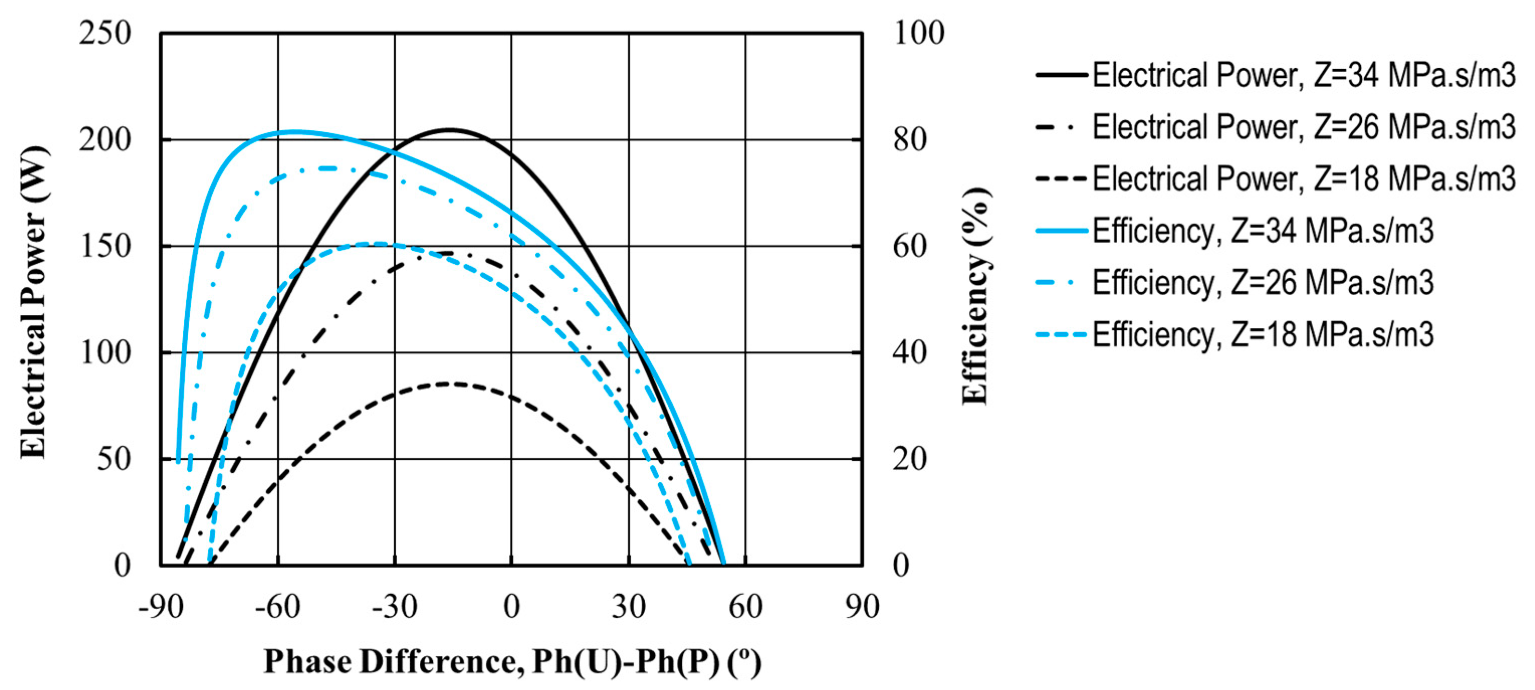
In addition to the system optimisation, DeltaEC was also used to study the favourable acoustic field for the linear alternator to generate high electrical power out of the acoustic input with high efficiency. Specifications of the linear alternator (Q-Drive 1S132M) were used as input values for the model.
Figure 2 shows the generated power (black curves) and efficiency (blue curves) at a frequency of 56 Hz. They are plotted as a function of phase difference between velocity and pressure. The local acoustic impedance (which is a parameter here) is shown in the legend. The simulation results confirm that the linear alternator generates higher electrical power and runs more efficiently at higher acoustic impedance. In addition, the phase difference of around 15° is favourable for the linear alternator to generate the highest power, while between 40–60° to run at highest possible efficiency.
This paper describes the experimental rig only in brief, since the full details can be found in [
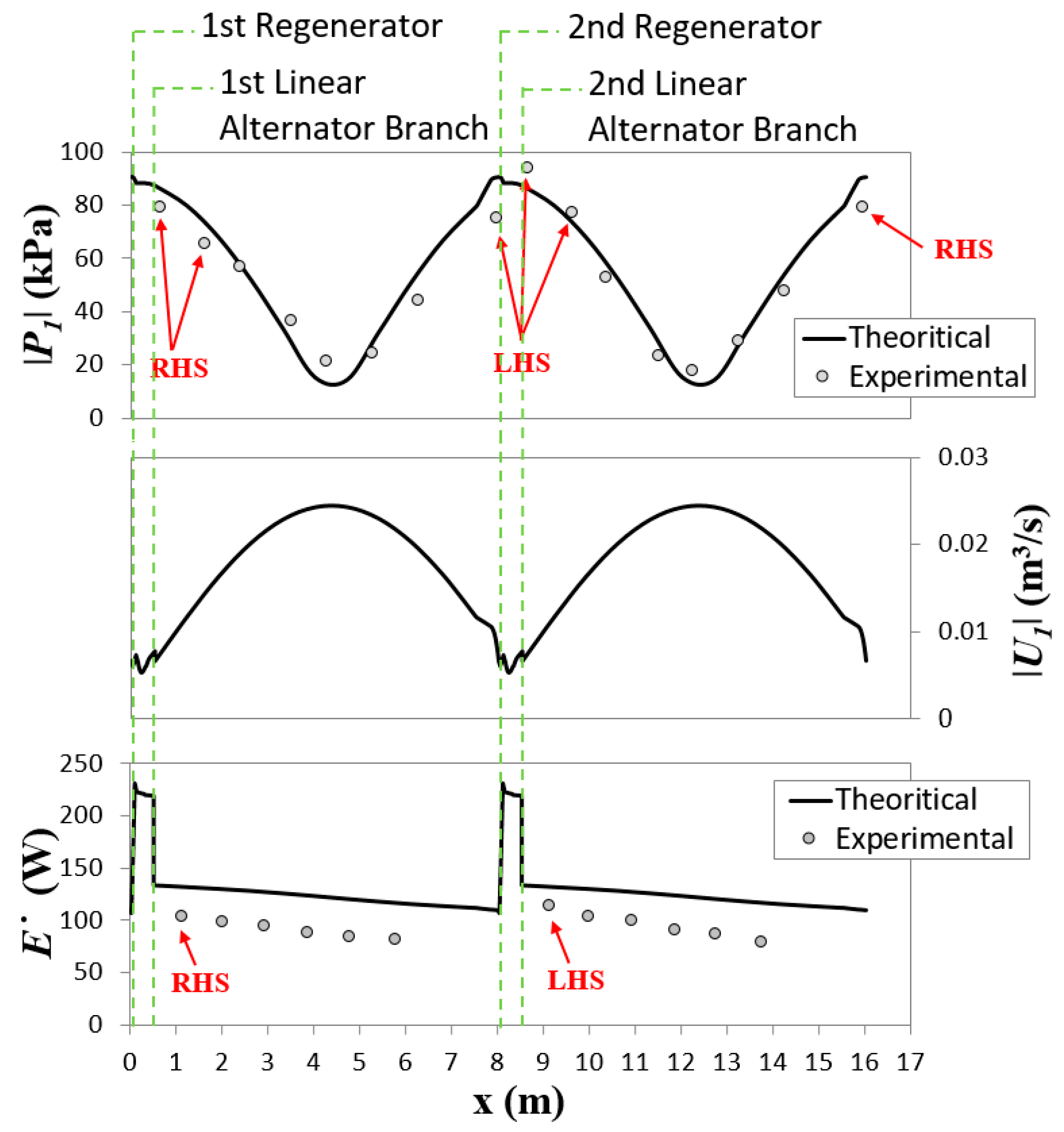
18]. The thermoacoustic generator is a 16.1 m long, looped tube two-stage thermoacoustic engine, and uses pressurized helium at 28 bar as the working gas. It runs at a frequency of 54.7 Hz. The simulation results for the one-wavelength acoustic field in the engine are presented in
Figure 3. The figure shows that the regenerators are located near maximum pressure and minimum volumetric velocity amplitudes to be near the highest acoustic impedance and minimize the viscus dissipation. The two branches leading to the linear alternator sides are placed near the regenerator to ensure the highest possible acoustic impedance at the linear alternator branches. The acoustic power distribution along the engine shows that the acoustic power is generated in regenerators and mainly dissipated through the linear alternator branches.
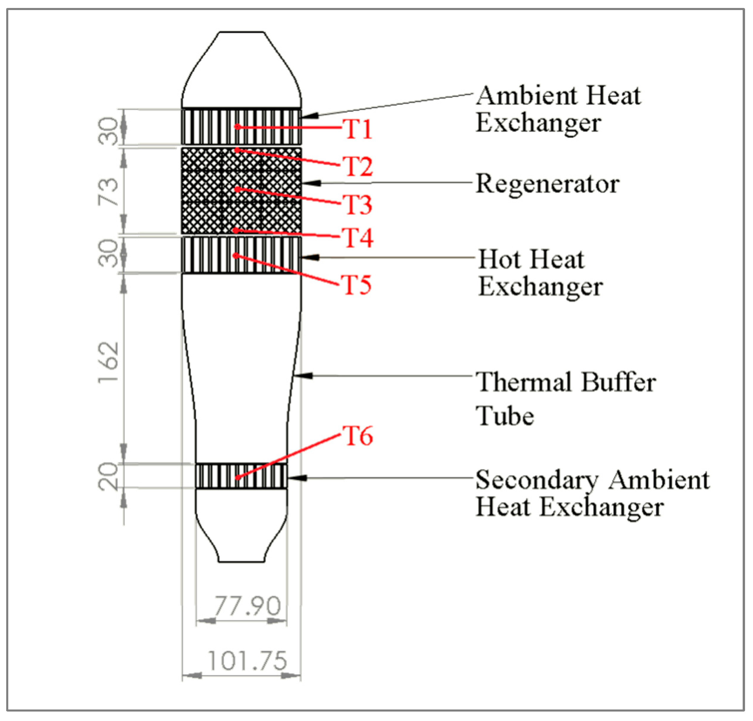
Figure 4 shows a cross-section of the thermoacoustic core. The regenerator holder, hot heat exchanger and thermal buffer tube have been manufactured as one piece to eliminate potential gas leakage problems which might appear at elevated temperatures at the seals of hot parts. The ambient heat exchanger is a cross flow heat exchanger having staggered fins at both water and helium flow directions. It is made out of a block of copper. The diameter of the heat exchanger on the helium side is 101.75 mm, and its thickness is 30 mm. The fins are 0.5 mm in width leaving 1 mm channels; on the helium side the fins are 8 mm long, while they are 5 mm long on the water side. At the design drive ratio, the peak-to-peak displacement is roughly half of the heat exchanger length. The porosity of the ambient heat exchanger is 31.2% on helium side.
The regenerator is made of 445 stainless steel mesh screen layers, piled up inside the regenerator holder. Regenerator length is 73 mm, and its diameter is 102 mm. The wire diameter in the mesh screen is 65 μm while the wire-to-wire aperture is 180 μm. On each end of the regenerator, there are coarse diamond mesh screens of 1.2 mm thickness, which act as spacers. The spacers allow the gas leaving the heat exchangers to mix and spread over the entire regenerator cross section. The regenerator hydraulic radius and the volume porosity have been calculated using the wire diameter, aperture and the amount of packed mesh per unit volume. The hydraulic radius is 60.5 μm and the volumetric porosity is 78.9%.
The hot heat exchanger has been manufactured from a low carbon steel. The choice of the material is based on a trade-off between the thermal conductivity and mechanical strength at elevated temperature. It has the face diameter of 102.2 mm (4 inch) and length of 40 mm along the flow direction. It is equipped with pairs of 100 W cartridge heaters. On the helium side, the comb-like structure creates channels of 1 mm width and fins that are 7 mm long and 0.5 mm thick. The porosity of the hot heat exchanger on the helium side is 34.4%. At the design amplitude, the peak-to-peak displacement is roughly one third of the heat exchanger length.
Below the hot heat exchanger is the thermal buffer tube providing thermal buffer between the hot and secondary ambient heat exchangers. It is 162 mm long having a conical middle section which reduces the internal diameter from 102.2 mm to 77.9 mm. The conical section is expected to reduce the Rayleigh streaming in the thermal buffer tube, as recommended by Swift [
1].
The last part of the thermoacoustic core is the secondary ambient heat exchanger. The purpose of this part is to prevent heat from flowing beyond the core into the resonator. It is similar to the main ambient heat exchanger but with smaller dimensions. It is made of copper and has a porosity of 38%. The diameter of the heat exchanger on helium side is 77.5 mm, and its thickness is 20 mm. The fins are 0.5 mm in width; the fins are 9 mm long on the helium side and 5 mm long on the water side. At the design amplitude, the peak-to-peak displacement is roughly equal to the heat exchanger thickness.
The acoustic network delivers the acoustic power generated in the thermoacoustic core to the linear alternator branch and the rest is fed to the other thermoacoustic core. The network comprises of a straight standard 1½ inch tube. The last 275 mm of the feedback loop is a standard 1-inch tube to adjust the phase difference at the linear alternator for a better performance. The linear alternator used in the rig is Q-Drive 1S132M. This alternator is asymmetric in that on one side the piston is exposed to the gas while the other side is connected to a shaft forming part of the electromagnetic armature. Subsequently, the gas flow on two sides of the piston is not symmetrical—this feature is being corrected to some extent by introducing bespoke PVC inserts on the armature side, cf. [
18].
3. Experimental Results
The experiment preparation starts with charging the engine with helium to 28 bar and then turning the cooling and heating systems on. The regenerators start generating weak oscillations when helium at the hot side of the regenerator reaches a temperature of 230 °C at a temperature difference of 185 °C. Normally, the engine does not amplify the weak acoustic oscillations (even at much higher temperature differences) to a level intense enough to drive the linear alternator. However, it has been found that in practice the intense acoustic wave can be excited by driving the linear alternator as an acoustic driver at a specific frequency. For instance, a few cycles of the piston excitation using a function generator and an amplifier at a frequency of 50.8 Hz was enough to excite the intense oscillation. This allows delivering an acoustic power to the cold side of the regenerator at a favourable acoustic phasing. An electrical control circuit was designed to protect the alternator and facilitate starting the engine. It switches the linear alternator connection in three ways based on the piston displacement measured by the laser displacement sensor: namely to function generator/amplifier, load resistance and a short circuit. At no oscillations present, the circuit connects the linear alternator to the function generator/amplifier which excites the piston for a few cycles at about 1.5 mm peak displacement. Once the engine amplifies the acoustic power and drives the piston over 2 mm peak displacement threshold, the circuit connects the linear alternator to the load resistance to dissipate the generated electricity and control the piston displacement. In case the engine drives the linear alternator close to its maximum stroke of 6 mm, the circuit switches the connection of the linear alternator to a short circuit to protect the alternator by stopping the piston oscillation.
At no oscillation condition, there is a high heat loss of about 450 W per stage from the hot heat exchanger (this value is deducted in performance calculation in this paper). As the hot heat exchanger is manufactured as one piece with the thermal buffer tube and the regenerator holder, the hot heat exchanger cannot be insulated from these two pieces. A possible way to reduce the conduction heat loss from the regenerator holder to the ambient heat exchanger is to place a low heat conductivity gasket between them. A gasket made out of thermiculite 715, Flexitallic model number SCRC04003T71515, was used. This gasket material has a low thermal conductivity of 0.3 W/m.K. The minimum available gasket thickness of 1.5 mm was selected. At this thickness, the gasket can seal up to 140 bar at a temperature of up to 540 °C.
The experiments showed that the insulating gasket improved the regenerator temperature difference and the performance of the engine. For example, the regenerator temperature difference increased from 297 °C to 308 °C and the generated electricity from 48.6 W (cf. previous work [
18]) to 62.2 W at 900 W heating power, 28 bar mean pressure and 30.8 Ω load resistance.
There is an acceptable agreement between the measurements and the calculated results. The circular symbols in
Figure 3 indicate the measured pressure amplitude and acoustic power (calculated using a two-microphone method, [
20]), while the continuous line shows the calculated values along the engine. The measured values of pressure amplitude showed small differences between corresponding points for the two stages. This is caused by the construction of the asymmetrical linear alternator. All the left-hand side (LHS) points which are facing the armature of the linear alternator have slightly higher amplitudes than the right-hand side (RHS) points which are facing a flat side of the piston.
3.1. Effect of Load Resistance
In the experiments, a resistive load was connected to the linear alternator to measure and dissipate the generated electricity. The load value varied from 26.3 Ω to 92.5 Ω. Any value lower than 26.3 Ω damps the oscillations and the performance decreases at loads higher than 92.5 Ω, at similar heating power and mean pressure. For the linear alternator acting alone, at the nominal operating frequency, an increase in the load resistance will normally lead to a decreased acoustic load imposed by the linear alternator upon the oscillatory flow into the branch. As a result, the acoustic pressure in the branch, as well as the acoustic pressure difference across the alternator, increase in amplitude. The piston displacement also increases slightly, and so the linear alternator with the branch act more like a standing wave resonator which will draw less power from the engine loop. When such an alternator is coupled to the engine loop (as is the case here), the resulting acoustic pressure in the engine loop is of a higher amplitude.
The linear alternator piston applies an acoustic load to the acoustic field at each of the linear alternator branches. The value of the load resistance dominates the acoustic load which dominates the acoustic field and performance of the engine.
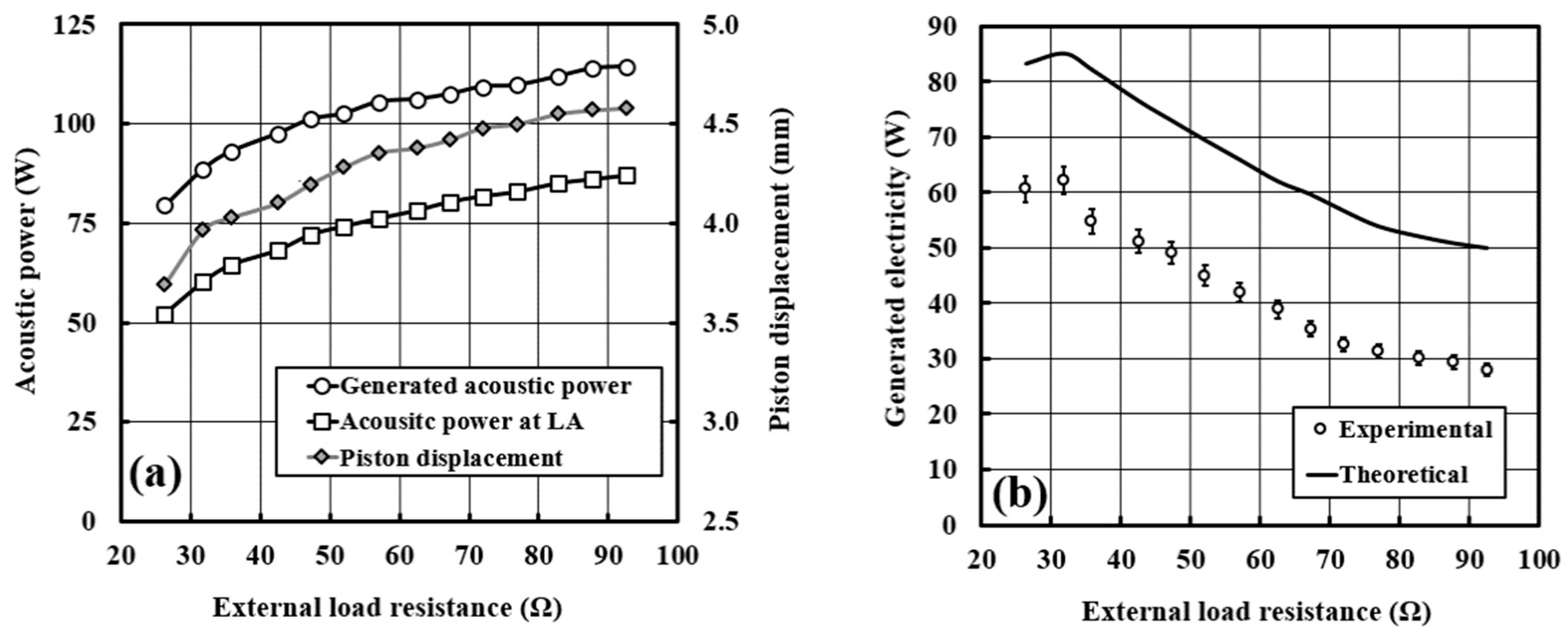
Figure 5a shows the experimental results for the acoustic power generated by one engine stage, the acoustic power delivered to one side of the linear alternator and the piston displacement at different load resistances. Increasing the load resistance will decrease the linear alternator acoustic load which allows the piston to oscillate at higher displacement.
Figure 5b shows the electricity output measured using the load resistance connected to the linear alternator against the predicted values obtained from the DeltaEC model. The experimental values are indicated by the symbols, while the continuous line shows the model prediction. The experimental values represent the average of four experimental readings, while the error bars correspond to their standard deviation. In experiments, the device generated 62.2 W of electricity at load resistance of 30.8 Ω (the best performance of the engine will be presented later in
Section 4.1). The load resistance, the amplitude of acoustic pressure at the linear alternator and the temperature differential across the regenerator taken from experiments were applied as the boundary conditions for the DeltaEC model. A maximum electrical power of 85.02 W was predicted when the load resistance is 30.8 Ω.
The experimental and simulated electricity output profiles are comparable at all magnitudes of load resistance. However, significant discrepancies are observed. The main reason is that the phase difference between the volumetric flow rate and pressure at the linear alternator in the experiment is not the linear alternator’s favourable acoustic condition set during modelling. For instance, the phase difference in the simulation is −30°, while in the experiment it is 10.5°.
Figure 2 shows that the linear alternator does not favour the experimental phase difference value. Unfortunately, when fitting the DeltaEC model to the experimental results one can only take care of a limited number of the most important parameters, for instance the pressure amplitudes and temperature data will take precedence over phase relationships. However, there are additional reasons for discrepancies between modelling and experiments. For example, acoustic streaming which occurs in the experiment (explained in
Section 4.2) and which is responsible for transferring heat from the hot to ambient heat exchanger is not included in the model. Similarly, the acoustic power dissipation through major and minor losses was calculated in the simulations using steady flow loss correlations for oscillating flow. In addition, DeltaEC performs calculations by integrating the one-dimensional wave and heat transfer equations, while the actual flow and heat transfer physics is three-dimensional in experiments. The accuracy of DeltaEC simulation results in predicting turbulence phenomena remains questionable, which may also be the underlying problem.
The power output of the electricity generator is a product of the acoustic power delivered to the alternator and its acoustic-to-electric transduction efficiency. The transduction efficiency should reach the maximum when the load resistance is equal to the coil resistance of the alternator [
21], i.e., 2 Ω. The electrical power produced is also proportional to the piston displacement to the power of two. This increases continuously as seen in
Figure 5a.
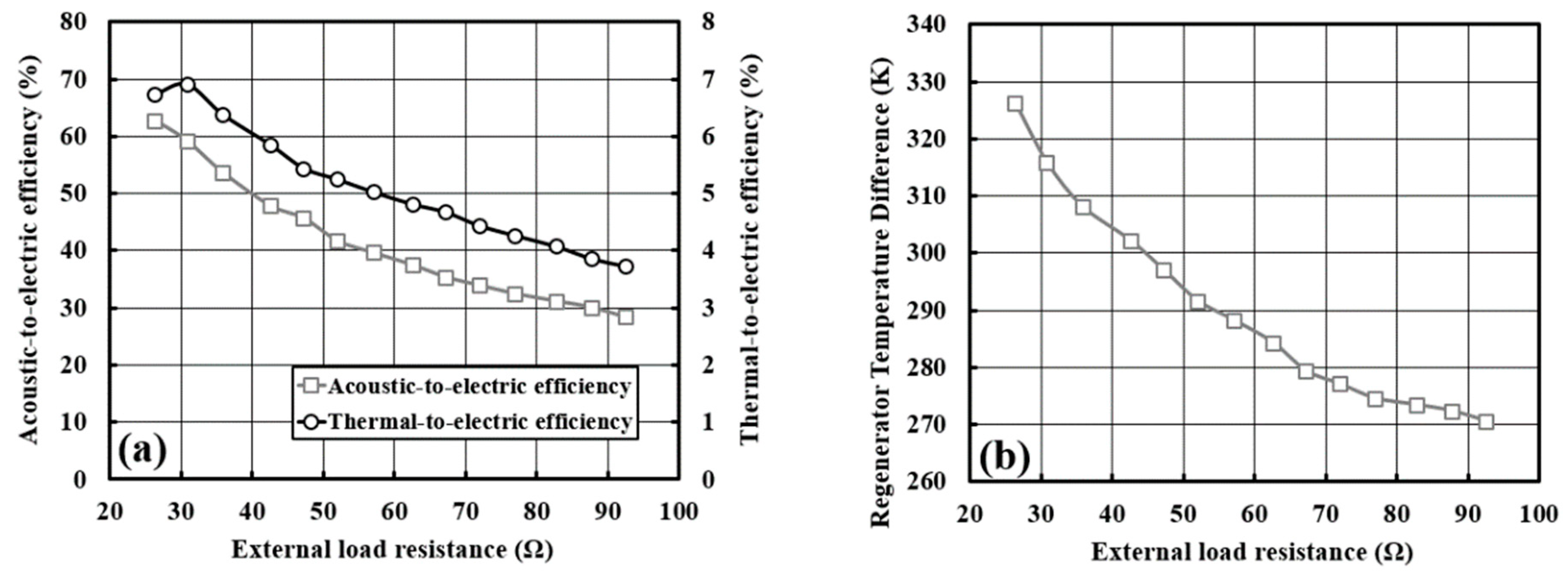
Figure 6a shows that the acoustic-to-electric efficiency falls from 62.7% to nearly 28.4% by increasing the load resistance from 26.3 Ω to 92.5 Ω. The thermal-to-electric efficiency reaches the maximum of 6.91% at the highest electrical output when applying a load resistance of 30.8 Ω.
Figure 6b shows the temperature difference measured across the regenerator (T2 and T4 shown in
Figure 4) at various load resistances. At the same heating power, the temperature differential across the regenerator reduces gradually vs. the load resistance. Clearly, the heat transfer between hot and ambient heat exchangers increases due to a high-volume flow rate, but unfortunately this is not coupled with the increase in electricity production. This is because, while the acoustic power increases (cf.
Figure 5a) the phasing between pressure and velocity (cf.
Figure 2) becomes less favourable, and so the electrical power extraction decreases.
3.2. Effect of Mean Pressure
The values of the mean pressure will affect both the power density of the acoustic field and the thermodynamic properties of the working gas. Swift et al. [
1] determined the power density factor to be
, where
is the speed of sound,
is the mean pressure and
is the cross-sectional area. Higher power density will enable the thermoacoustic engine to run at higher acoustic impedance which in turn will allow higher acoustic to electric conversion at the linear alternator [
18]. Varying the mean pressure changes the thermodynamic properties of the gas, including density and thermal and viscous penetration depths. These influence the processes of energy conversion in the thermoacoustic system. The mean pressure was varied in the range of 14–28 bar, at a load resistance of 30.8 Ω and heating power of 900 W. Any mean pressure less than 14 bar led to a non-harmonic oscillation which failed to maintain itself and was quickly damped.
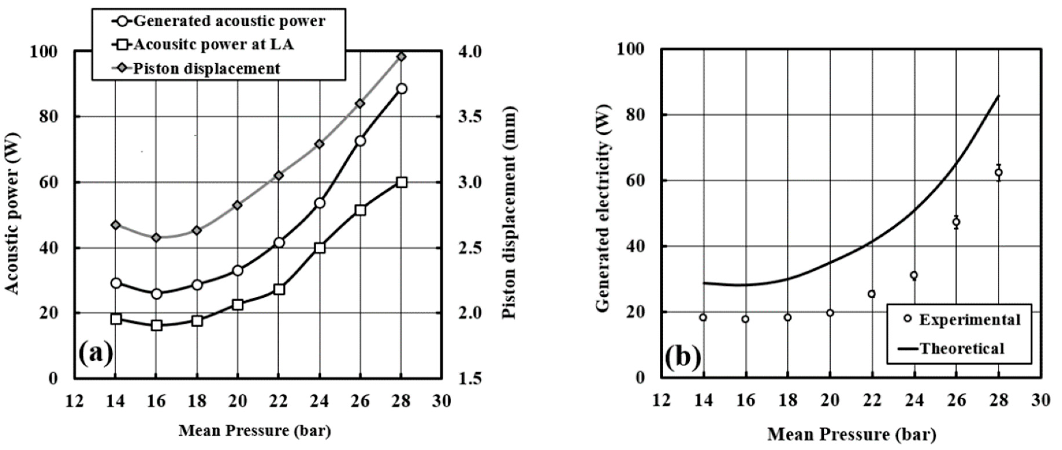
Figure 7a shows the experimental values of the net acoustic power generated in one engine stage, the acoustic power delivered to one side of the linear alternator and the piston displacement vs. load resistance applied. It indicates that the engine performs better at higher mean pressure, as it provides higher power density and favourable phase difference to the linear alternator.
Figure 7b shows the measured electrical power and the values predicted by the DeltaEC model. Symbols denote the experimental results, while the line shows the model prediction. In experiments, the engine generated 62.2 W of electricity at mean pressure of 28 bar (the best performance of the engine will be presented later in
Section 4.1). The mean pressure, load resistance, the amplitude of acoustic pressure at the linear alternator and the measured temperature differential across the regenerator were applied as DeltaEC boundary conditions. A maximum electrical power of 85.02 W was predicted when the mean pressure is 28 bar. There is a clear trend of decreasing the generated electrical power with the decreasing mean pressure. The experimental and simulated electricity output profiles are comparable at all magnitudes of mean pressure. However, significant discrepancies are observed, which were explained in
Section 3.1 in some detail and these explanations are applicable here too. Additional
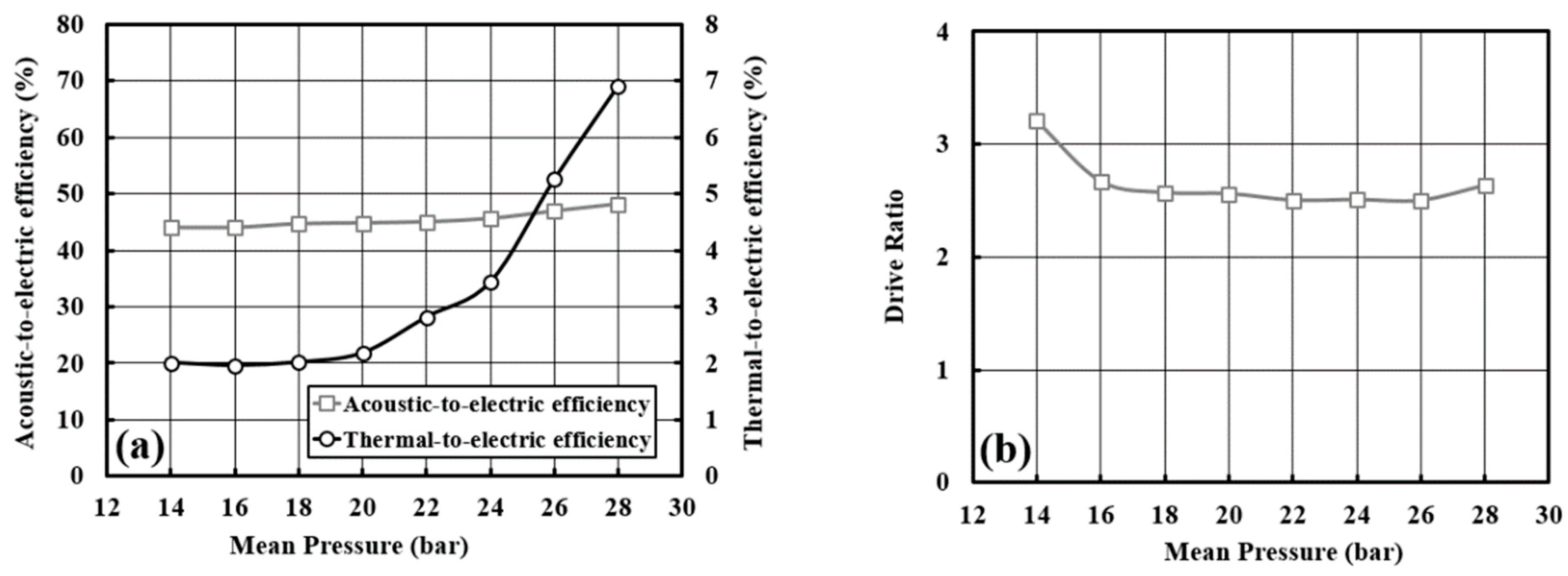
Figure 8 shows the effect of mean gas pressure on the acoustic-to-electric efficiency and thermal-to-electric efficiency (cf.
Figure 8a) and the measured drive ratio (cf.
Figure 8b).
Focusing on the low mean pressure range, it is not clear why the generated electrical power, generated acoustic power, drive ratio and piston displacement increase slightly when the mean pressure drops from 16 to 14 bar. Theoretically, these values should decrease based on the argument of power density being proportional to mean pressure. Most likely, this counterintuitive performance enhancement might be attributed to a phase difference at the regenerator being closer to the traveling wave for 14 bar (compared to 16 bar), which could lead to generating a higher acoustic power. Swift [
1] pointed out that a resonator channel acts as an acoustic inertance and compliance simultaneously. Both contribute to the behaviour of the wave propagation in the channel. However, reducing the mean pressure increases the acoustic compliance effect which shifts the volumetric flow rate phase, while decreasing the acoustic inertance effect of a resonator which shifts the pressure phase. Unfortunately, the current setup does not allow the detailed measurements to validate this point. However, it is possible to inspect the DeltaEC modelling results in terms of the phase angle between oscillating pressure and volumetric velocity. When the mean pressure reduces from 28 to 16 bar the phase angle increases from 58.9° to 68.4°, i.e., the wave becomes “less travelling” and “more standing”. On the other hand, a further decrease of mean pressure from 16 to 14 bar causes the phase angle to decrease from 68.4° to 68.0° to make the wave slightly “more travelling” again, which explains the apparent improvement of generator performance.
3.3. Effect of Heating Power
Heating power and oscillation intensity are the two parameters determining the regenerator hot side temperature. However, heating power is the dominant parameter determining the ability to maintain a high temperature difference across the regenerator during the oscillation. In this section, the value of the heating power represents the summation of the equal heating power of the two stages. At no oscillation, there is a high heat loss of about 450 W per stage from the hot heat exchanger which is deducted in performance calculations in this paper. The heating power was varied from the minimum power of 500 W capable of maintaining oscillations to a maximum of 1700 W, at 28 bar mean pressure and load resistance of 30.8 Ω.
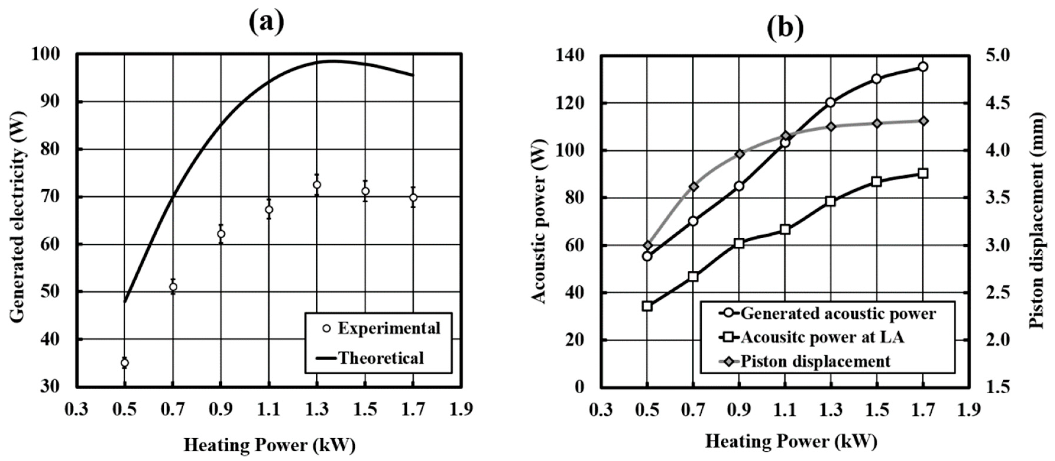
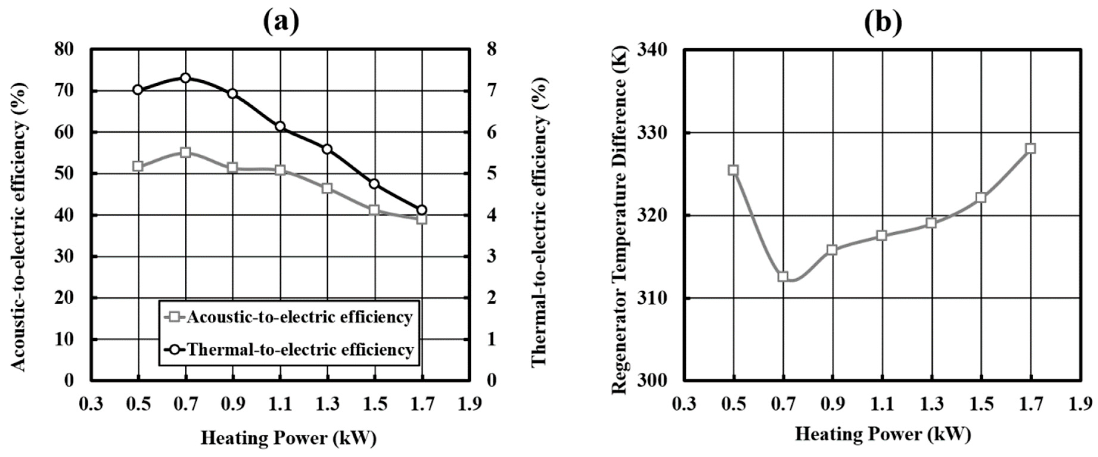
Figure 9a shows the generated electrical power at different heating power for both experiments and simulation. For both, the maximum is reached at a heating power of 1300 W. In the experiments, a maximum electrical power output of 72.5 W was obtained at 5.58% of thermal-to-electric efficiency, while the maximum efficiency of 7.3% was obtained at heating power of 700 W generating 51.1 W of electricity, as shown in
Figure 10a. The thermal-to-electric efficiency decreases between 700 W and 1700 W.
The existence of maximum generated electricity for heat input of 1300 W can be explained as a combination of two effects: On the one hand, increasing the heating power leads to the increase of the regenerator temperature difference (
Figure 10b), generated acoustic power, acoustic power at the linear alternator and the piston displacement (
Figure 9b). At the same time, the measured difference between volumetric flow phase and pressure phase increases towards the unfavourable values for the linear alternator which leads to the decrease in the alternator acoustic-to-electric efficiency, as shown in
Figure 10a. In experiments, the phase difference at 900 W heating power is 10.5° and it increases up to 34° at 1700 heating power.
Figure 2 shows how shifting the phase difference affects the generated power and efficiency of the linear alternator. These competing effects lead to a maximum electricity production at 1300 W heating power rather than the highest heating power.
The regenerator acts as an acoustic power amplifier. However, the flow resistance inside the regenerator plays a vital role in the power amplification as reported by Yu and Jaworski [
22]. At a certain acoustic impedance, the flow resistance will dissipate most of the acoustic power fed through the regenerator cold end and this will decrease the acoustic power generation. Under such circumstances, the externally set temperature gradient will not have a significant effect. In fact, low conversion of heat into sound will lead to heating up of the regenerator hot side as shown at 500 W heating power in
Figure 10b.
4. System Debugging
The aim of the debugging and optimization process was to solve and/or eliminate two problems: self-starting and streaming.
4.1. Start-Up Improvement
As mentioned in
Section 3, the engine in its baseline configuration could not self-start and required “kick-starting” where a few cycles of initial excitation came from externally exciting the linear alternator. The successful solution to this problem turned out to be a slight reduction in the flow resistance. Yu and Jaworski [
22] highlighted the relation between the flow resistance and local acoustic impedance and their effect on the net acoustic power and acoustic power input. It was concluded that the flow resistance plays a key role in determining the regenerator impedance as it determines the volumetric flow rate at a specific pressure amplitude. At a given pressure amplitude, the higher flow resistance increases the acoustic impedance by decreasing the volumetric flow rate.
Reducing the flow resistance in the regenerator was a possible solution to reduce the acoustic impedance, and hence increase the acoustic power leaving the regenerator, at specific acoustic power entering it, by reducing the acoustic power dissipated at the regenerator. The flow resistance could be reduced by decreasing the length of the regenerator or increasing the cross-sectional area. In the current research, the regenerator holder was welded to the hot heat exchanger and a heavy flange, therefore its length and diameter are fixed. The only way to reduce the regenerator length is to replace some of the regenerator mesh screens with coarse mesh (same as used for the spacers, cf.
Section 2). The coarse mesh screens were applied on the cold side of the regenerator, for ease of replacement.
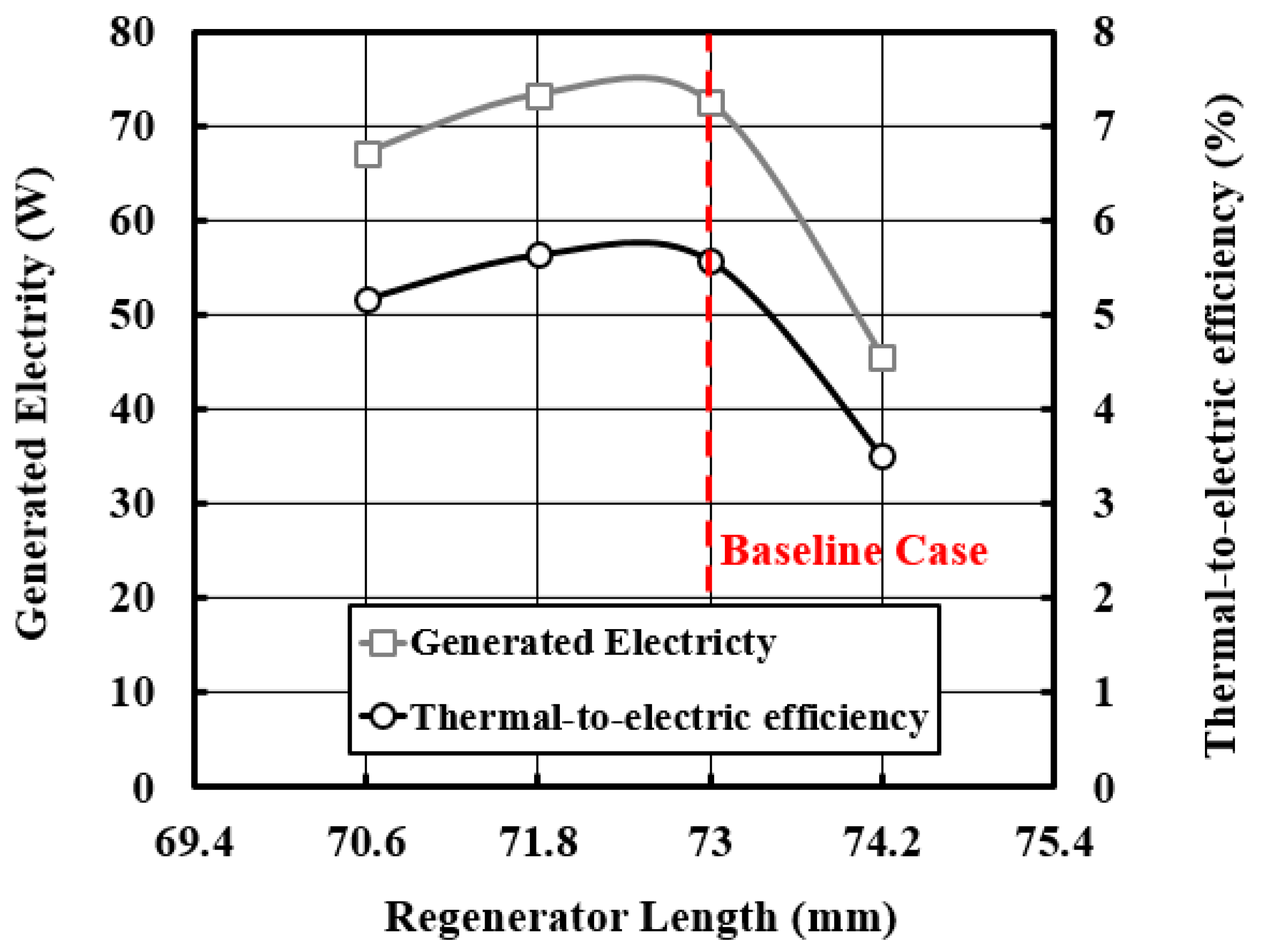
The effect of the regenerator length was investigated experimentally at 30.8 Ω load resistance, 1300 W heating power and 28 bar mean pressure. The regenerator length was increased once and reduced twice by a 1.2 mm step, which is the thickness of a single coarse mesh.
The engine self-starts at a regenerator length of 71.8 mm and 70.6 mm. The oscillation starts at a regenerator temperature difference of 280 °C. The reduction of the flow resistance was found to enhance the performance by a very small fraction.
Figure 11 shows the effect of regenerator length on the generated electricity and thermal-to-electric efficiency. The new maximum generated electricity is 73.3 W at 5.64% thermal-to-electric efficiency. The relative Carnot efficiency is 11.3%, drive ratio is 3.4% at a regenerator temperature difference of 288.8 °C.
4.2. Efforts Towards Supressing Streaming
Gedeon streaming exists in looped-tube or toroidal devices only. The reason is that a closed loop topology encourages a steady flow to circulate along such resonators. Gedeon [
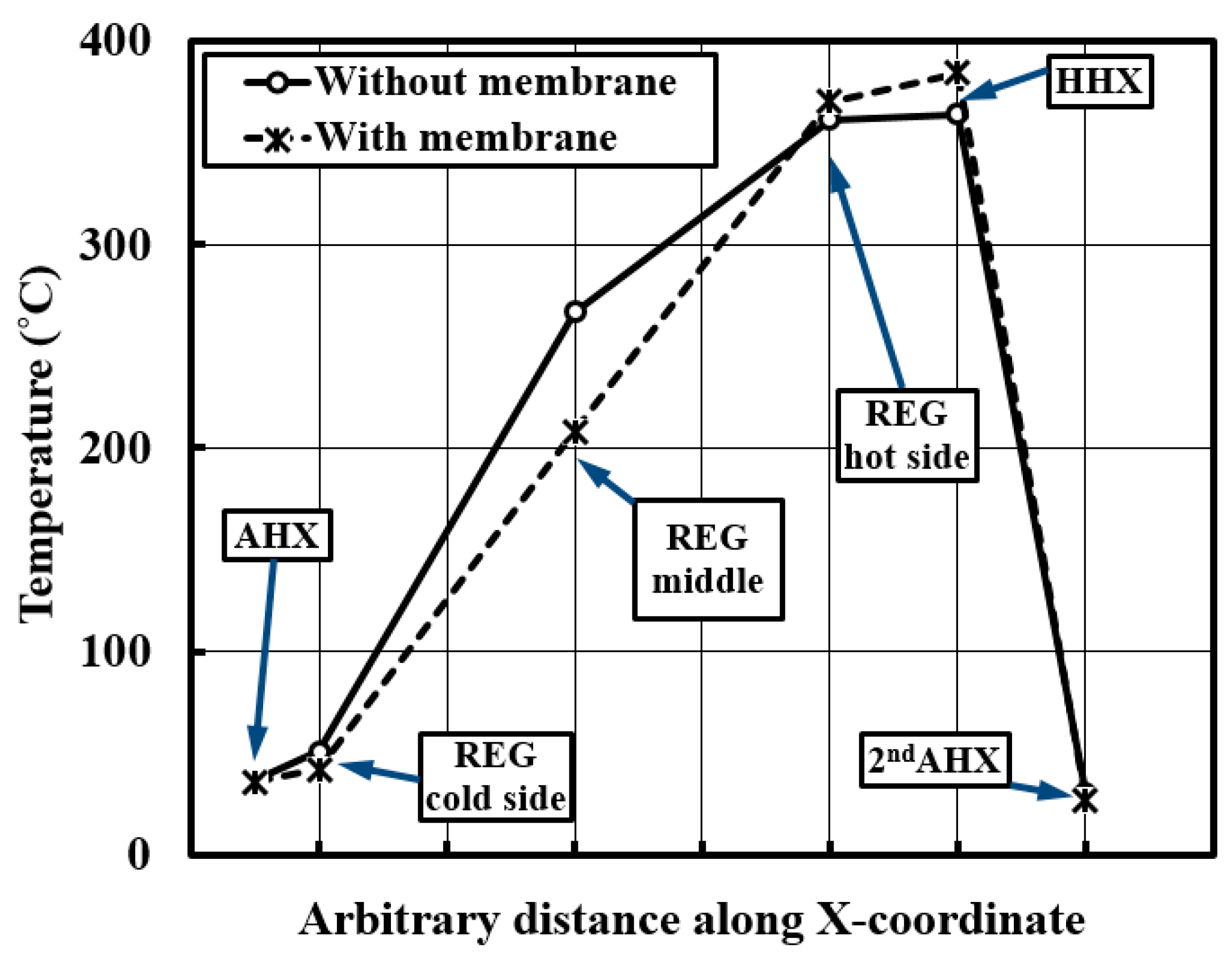
23] explained it as mass flow in the Stirling engines and pulse tube cryocoolers with a closed loop which leads to time-averaged convection enthalpy flux from the hot to the cold side. This phenomenon wastes heat in a thermoacoustic engine by removing heat from the hot side to the ambient of the regenerator without generating acoustic power. The devices suffering from a non-zero mass flow through the porous medium will show a non-linear temperature distribution within the porous medium. All the experimental tests showed a non-uniform temperature distribution, an example being shown in
Figure 12. Many researchers [
1,
24,
25] summarized that this kind of streaming can be suppressed either by placing a latex membrane or applying a non-symmetric flow resistance such as jet pump. The latex or elastic membrane will be transparent to the acoustic power while forming a barrier to the streaming flow, hence eliminating it.
The elastic membrane needs to be placed close to the minimum volumetric flow rate to suppress this streaming at the lowest possible acoustic power loss.
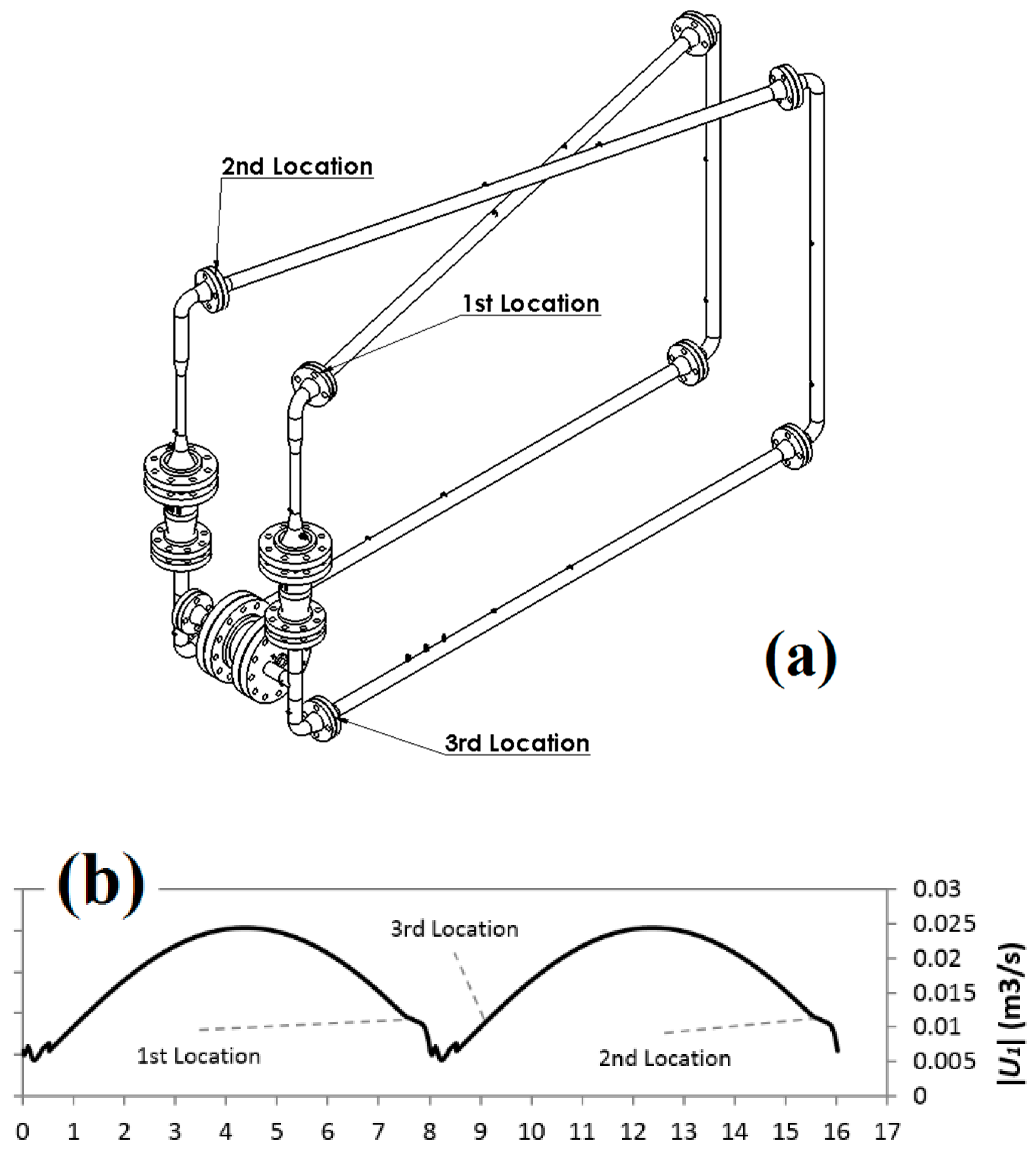
Figure 3 shows that the best location is near the main ambient heat exchanger. Unfortunately, this location in the experimental rig was used to feed through the thermocouples, and hence, the membrane could not be placed there. Potential locations are between two flanges at three locations, as shown in
Figure 13a.
Figure 13b shows the locations of the membrane with reference to the theoretical volumetric flow rate.
The membrane was selected based on its material elastic properties and thickness. A sheet of 100% genuine latex of 0.25 mm thickness, was used.
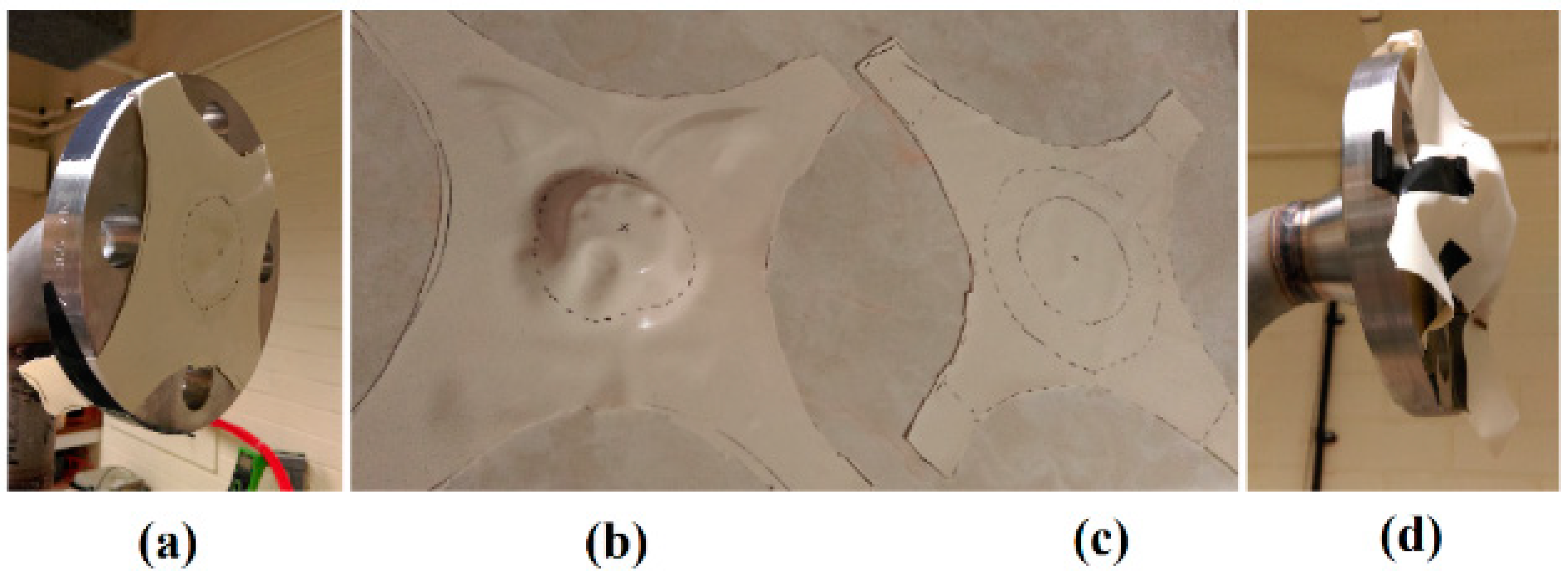
Figure 14b–d show the three profiles of the membrane that were tested: flat, concave and loose.
Figure 14a shows an example of an assembled membrane. All three profiles were used in single and double locations. They were used on their own at the 1st and 3rd location, as shown in
Figure 13a, and together at the 1st and 2nd location. The concave profile was made by continuous stretching and heat treatment.
The experimental results showed that a single membrane placed at any location or a double membrane can suppress the Gedeon streaming and generate a uniform temperature distribution along the regenerator, as shown in
Figure 12. Unfortunately, the membranes also act as flow resistance and dissipate the acoustic power. The generated electricity for the tested membrane locations and profiles varied from 0.5 W to 4.2 W. The highest performance was achieved by using one concave membrane at the 1st location.
5. Feedback Loop Optimization
This section presents a DeltaEC study to propose a modified design of the experimental apparatus to reduce its size. In particular, the new model considers shortening the feedback loop while keeping the current thermoacoustic cores and alternator holder unchanged. The current engine is 16.1 m long, of which approximately 15 m is a constant diameter feedback loop.
The function of the feedback loop is to deliver acoustic power to the regenerator at a favourable acoustic phasing. The current uniform section feedback loop shifts the pressure phase by 175° and volumetric flow rate phase by 50°. This phase shift could be achieved within a much shorter length by using a variable cross-section feedback loop. A wide cross-section pipe shifts the phase of the volumetric velocity since it acts as an acoustic compliance, while a narrow pipe shifts the pressure phase since it acts as an acoustic inertance [
1]. The combination of compliance-inertance loop shifts the acoustic phasing in much shorter length than the constant diameter loop.
Many configurations of feedback loop combining inertances and compliances were studied, however, the paper will present the one that provides the shortest length without dissipating a high share of engine’s generated acoustic power. Firstly, DeltaEC was used to simulate the acoustic field in the feedback loop only. The model considered the acoustic wave characteristics at the beginning and the end of the thermoacoustic core as boundary conditions of the compliance-inertance feedback loop. The new feedback loop reduced the engine length from 16.1 to 7.5 m. Subsequently, it was tested numerically on a full model and showed the same performance.
For a pipe of a certain length and diameter, the phase shifting capabilities strongly depend on the acoustic wave characteristics at the inlet. In this study, the phase shifting results for the local acoustic wave at the engine feedback inlet are shown in
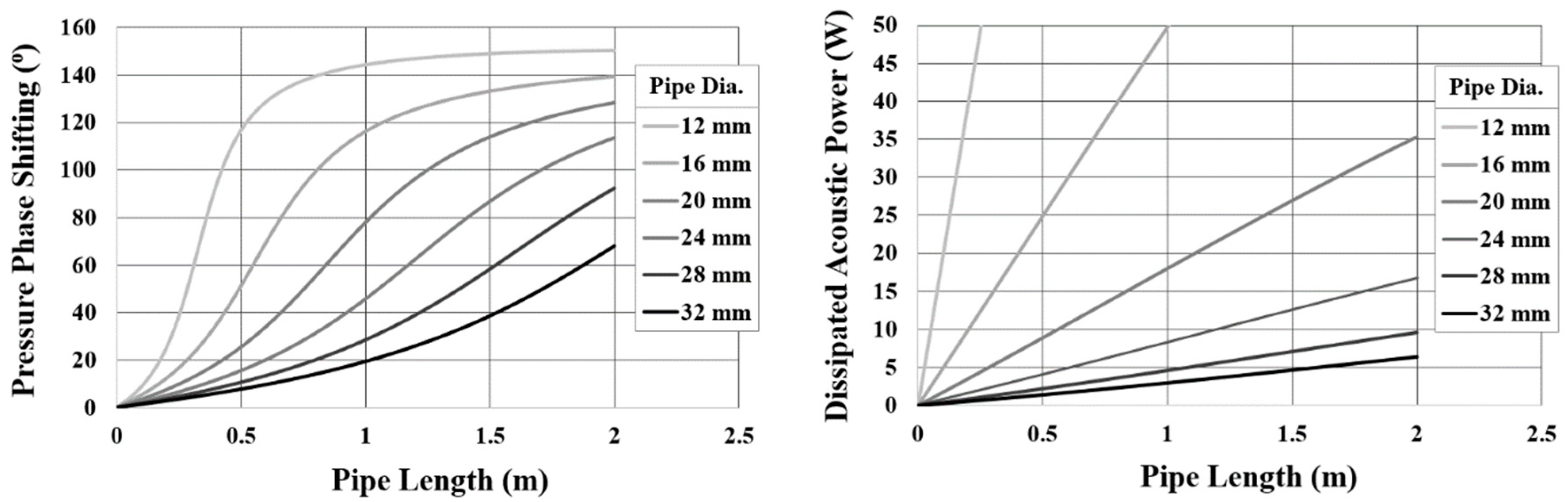
Figure 15. The selection of the pipe dimensions to act as an acoustic inertance is based on the pressure phase shifting and acoustic power dissipation.
Figure 15 shows an example of the pressure phase shifting and acoustic power dissipation for different sizes of pipes at an acoustic impedance of 5.1 M Pa∙s/m
3, 55° phase difference and 56.6 Hz frequency (which are the values at the inlet of the feedback loop to be replaced). A small diameter pipe can shift the pressure phase at a shorter length than larger diameter, however, it will dissipate higher acoustic power. For every pipe diameter there is a length range that appears to be very sensitive to the pressure phase shifting. This region needs to be avoided.
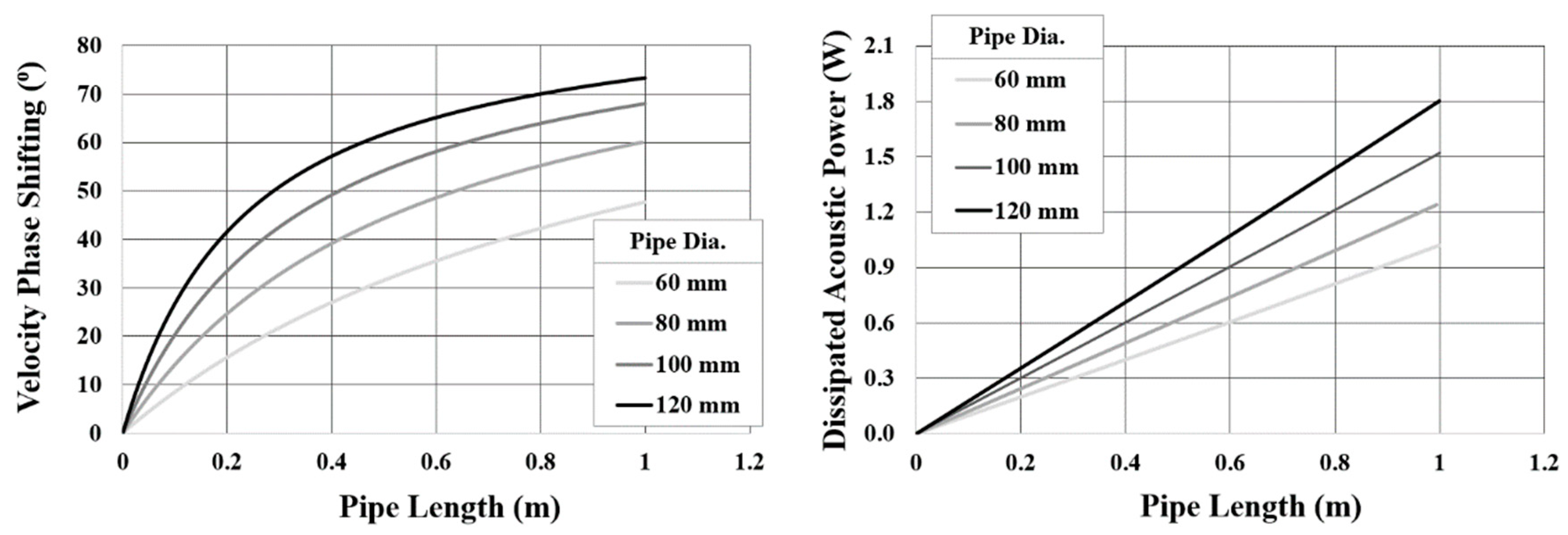
Large diameter pipe shifts the velocity phase at low acoustic power dissipation. The phase shifting capabilities strongly depend on the acoustic wave characteristics at the inlet. The selection of the pipe diameter and length is based on the required phase shifting, at the acoustic wave characteristics at the inlet.
Figure 16 shows an example of the effect of pipe length and diameter on the velocity phase shifting at an acoustic impedance of 3.8 M Pa∙s/m
3, 39° phase difference and 56.6 Hz frequency (which are the values in the middle of the feedback loop where the compliance will be placed). Similar to the selection of inertance, the steep change regions of the phase shifting need to be avoided for better solution stability.
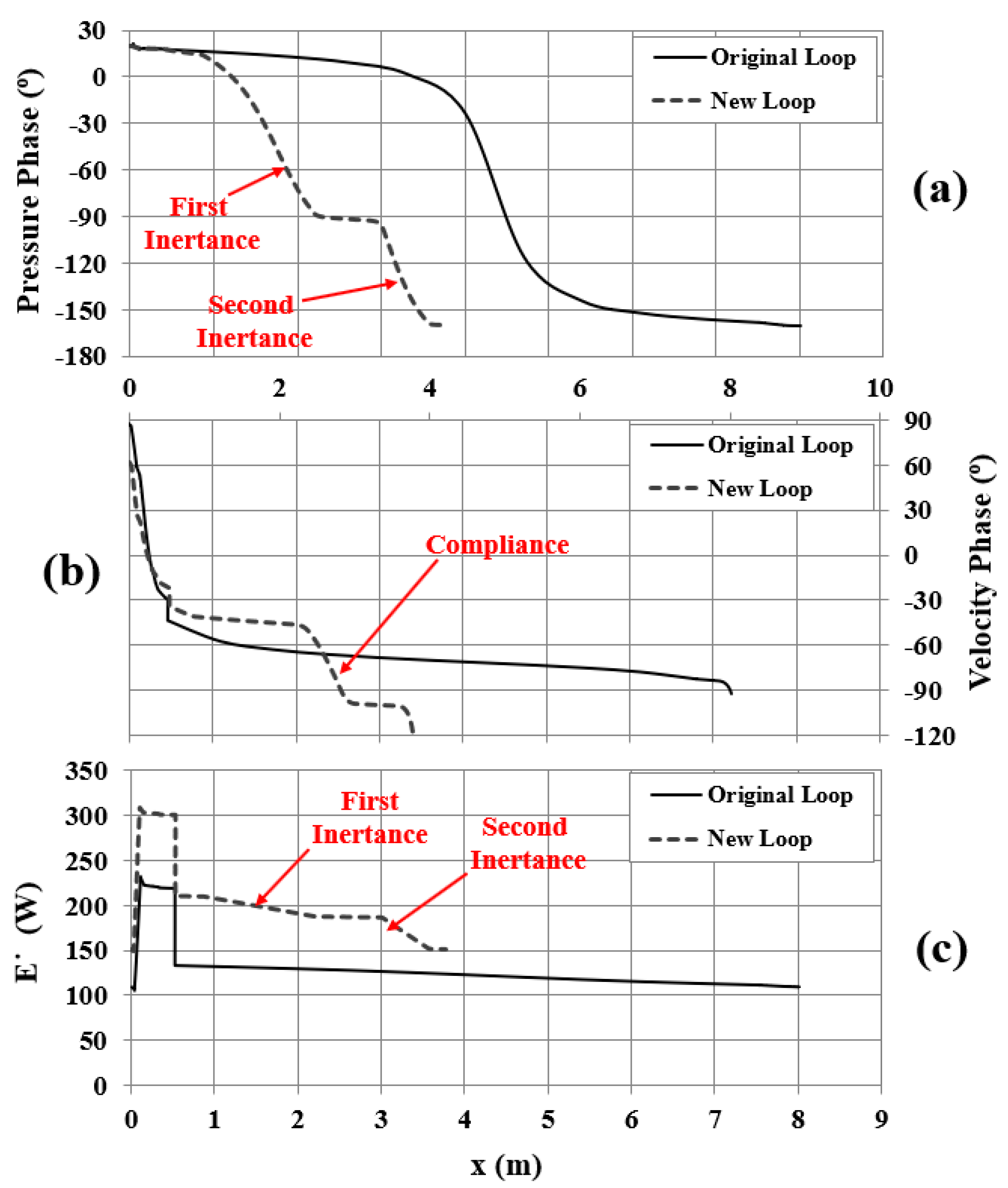
The best feedback loop configuration studied consisted of inertance-compliance-inertance. The inertance was split into two parts with a compliance sandwiched between them so that the inertance after the compliance will be in lower acoustic impedance region. This will allow the use of a thinner pipe in the second inertance (after the compliance) which will lead to a shorter feedback loop without creating a high acoustic power loss. After continuous optimisation process, the ideal diameters of the inertances and compliance were replaced by those available for the commercially available pipes. This generated some discrepancy which was actually found to be advantageous as the new configuration allowed a reduction of the phase difference near the middle of the regenerator closer to the traveling wave phase difference (namely from 26° to 9°). This helped to increase the generated acoustic power, at a similar regenerator temperature difference, from 123.5 W to 159.5 W. However, the extra generated acoustic power is dissipated in the feedback loop. The original feedback loop dissipates 23.8 W while the new loop dissipates 59.5 W, as shown in
Figure 17c.
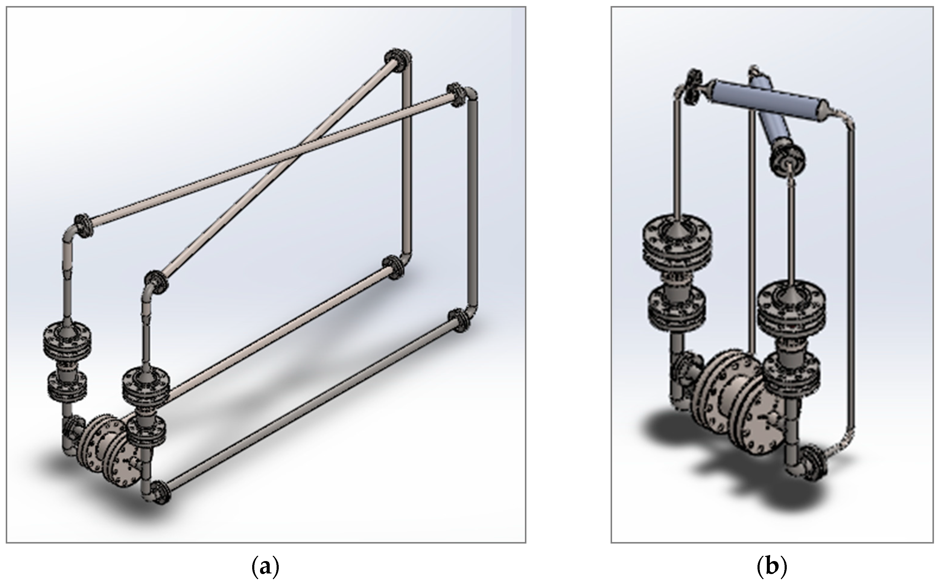
Figure 18 compares the engine configuration for both old and new feedback loops.
Figure 17 compares the pressure phase, velocity phase and acoustic power in one stage for the original and new feedback loop. The first section of the feedback loop is a 1½ inch diameter pipe with 300 mm length, which is part of the previous configuration. This is followed by a standard cone leading to the first inertance which is 1313 mm long and has a ¾ inch (20.9 mm) diameter. This shifts the pressure phase by approximately 100°, as shown in
Figure 17a. The acoustic compliance is 420 mm long and 3 inches (77.9 mm) in diameter, which shifts the volumetric flow velocity phase by approximately 40°, as shown in
Figure 17b. The second inertance is 584 mm long with dimeter of ½ (12.2 mm) inch, and shifts the pressure phase by approximately 62°, as shown in
Figure 17a. Both reducers connecting the compliance to the two inertances are non-standard, and of 50 mm length. The length and diameter of the two inertances and compliance were carefully optimized aiming to achieve the acoustic conditions at the shortest length possible.
6. Conclusions
Current work is focused on detailed studies and potential further improvements of a two-stage traveling-wave thermoacoustic engine. Here, the configuration of two identical half-wavelength stages allows the coupling of the linear alternator to two points with out-of-phase acoustic field, i.e., in so-called “push-pull” mode in an attempt to improve the impedance matching of the alternator to the engine, as well as reduce the ultimate cost by requiring only one alternator for two power extraction points. Modelling approaches are combined with experimental work in order to improve the overall performance of the prototype as well as improve the design to achieve more compact size.
In particular, the work presented here deals with system debugging, for instance improvements in electrical power output through limiting the axial heat leaks, and investigating the effects of regenerator length (i.e., regenerator impedance) on the start-up conditions in order to allow the engine self-excite without external power input and application of elastic membrane to eliminate Gedeon streaming. In addition, the paper presents a detailed account of the characterisation of the electricity generator system from the point of view of the mean pressure (range 14–28 bar) and heating power (500–1700 W) and load resistance (26.3 Ω to 92.5 Ω). It was found that the maximum electricity generated can reach 73.3 W at the heat input of 1300 W, load resistance of 30.8 Ω and mean pressure of 28 bar, with the overall thermal-to-electric efficiency of 5.64%. The maximum thermal-to-electric efficiency of 7.3% was obtained at heat input power of 700 W, while generating 51.1 W of electricity.
Finally, a design exercise was carried out aiming at reducing the size of the device while maintaining the same levels of performance. DeltaEC simulations have shown that introducing an inertance-compliance-inertance coupling instead of the constant diameter feedback pipe can reduce the resonator length from 16.1 m to 7.5 m, leading to a much smaller volume of the device.
Author Contributions
A.J.J. and X.M. guided the research. A.H. carried out the research by conceptualising the design, DeltaEC modelling, experimental data collection and producing the first draft. All authors critically evaluated the data and contributed to improving the manuscript through a number of iterations, in particular interpretation and discussion.
Funding
This research was funded by Royal Society Industry Fellowship scheme (Ref. IF110094, 2012-2015) and EPSRC UK under HARP2 programme (Ref. EP/R023328/1, 2018-2021).
Acknowledgments
Artur J. Jaworski acknowledges funding from the Royal Society Industry Fellowship scheme (Ref. IF110094, 2012-2015) and EPSRC UK under HARP2 programme (Ref. EP/R023328/1, 2018-2021). All authors acknowledge Innovate UK for financial support under TITAN project (ref no. 131497).
Conflicts of Interest
The authors declare no conflict of interest.
References
- Swift, G.W. Thermoacoustics: A Unifying Perspective for Some Engines and Refrigerators; Acoustical Society of America (through the American Institute of Physics): Melville, NY, USA, 2002. [Google Scholar]
- Luo, E.; Dai, W.; Zhang, Y.; Ling, H. Thermoacoustically driven refrigerator with double thermoacoustic-Stirling cycles. Appl. Phys. Lett. 2006, 88, 074102. [Google Scholar] [CrossRef]
- Dai, W.; Luo, E.; Hu, J.; Ling, H. A heat-driven thermoacoustic cooler capable of reaching liquid nitrogen temperature. Appl. Phys. Lett. 2005, 86, 224103. [Google Scholar] [CrossRef]
- Dai, W.; Yu, G.; Zhu, S.; Luo, E. 300 Hz thermoacoustically driven pulse tube cooler for temperature below 100 K. Appl. Phys. Lett. 2007, 90, 024104. [Google Scholar] [CrossRef]
- Yazaki, T.; Iwata, A.; Maekawa, T.; Tominaga, A. Traveling wave thermoacoustic engine in a looped tube. Phys. Rev. Lett. 1998, 81, 3128. [Google Scholar] [CrossRef]
- Chen, B.; Yousif, A.A.; Riley, P.H.; Hann, D.B. Development and assessment of thermoacoustic generators operating by waste heat from cooking stove. Engineering 2012, 4, 25859. [Google Scholar] [CrossRef]
- Zhang, X.; Chang, J. Onset and steady-operation features of low temperature differential multi-stage travelling wave thermoacoustic engines for low grade energy utilization. Energy Convers. Manag. 2015, 105, 810–816. [Google Scholar] [CrossRef]
- de Blok, K. Novel 4-stage traveling wave thermoacoustic power generator. In Proceedings of the ASME 2010 3rd Joint US-European Fluids Engineering Summer Meeting Collocated with 8th International Conference on Nanochannels, Microchannels, and Minichannels, Montreal, QC, Canada, 1–5 August 2010; pp. 73–79. [Google Scholar]
- Hu, J.Y.; Luo, E.C.; Zhang, L.M.; Chen, Y.Y.; Wu, Z.H.; Gao, B. Analysis of a displacer-coupled multi-stage thermoacoustic-Stirling engine. Energy 2018, 145, 507–514. [Google Scholar] [CrossRef]
- de Blok, K. Multi-stage traveling wave thermoacoustics in practice. In Proceedings of the 19th International Congress on Sound and Vibration, Vilnius, Lithuania, 8–12 July 2012. [Google Scholar]
- Zhang, X.; Chang, J.; Cai, S.; Hu, J. A multi-stage travelling wave thermoacoustic engine driven refrigerator and operation features for utilizing low grade energy. Energy Convers. Manag. 2016, 114, 224–233. [Google Scholar] [CrossRef]
- Yang, R.; Wang, Y.; Jin, T.; Feng, Y.; Tang, K. Development of a three-stage looped thermoacoustic electric generator capable of utilizing heat source below 120 C. Energy Convers. Manag. 2018, 155, 161–168. [Google Scholar] [CrossRef]
- Yang, R.; Wang, Y.; Feng, Y.; Jin, T.; Tang, K. Performance of a looped thermoacoustic engine with multiple loads capable of utilizing heat source below 200 °C. Appl. Therm. Eng. 2019, 148, 516–523. [Google Scholar] [CrossRef]
- Li, L.; Wu, Z.; Hu, J.; Yu, G.; Luo, E.; Dai, W. A novel heat-driven thermoacoustic natural gas liquefaction system. Part I: Coupling between refrigerator and linear motor. Energy 2016, 117, 523–529. [Google Scholar] [CrossRef]
- Li, D.; Wu, Z.; Luo, E.; Zhang, L. Experimental Investigation on the Conversion between Heat and Power of the kW-class Thermoacoustic Engine. Energy Procedia 2014, 61, 1058–1062. [Google Scholar]
- Wu, Z.; Yu, G.; Zhang, L.; Dai, W.; Luo, E. Development of a 3kW double-acting thermoacoustic Stirling electric generator. Appl. Energy 2014, 136, 866–872. [Google Scholar] [CrossRef]
- Bi, T.; Wu, Z.; Zhang, L.; Yu, G.; Luo, E.; Dai, W. Development of a 5kW traveling-wave thermoacoustic electric generator. Appl. Energy 2017, 185, 1355–1361. [Google Scholar] [CrossRef]
- Hamood, A.; Jaworski, A.J.; Mao, X.; Simpson, K. Design and construction of a two-stage thermoacoustic electricity generator with push-pull linear alternator. Energy 2018, 144, 61–72. [Google Scholar] [CrossRef]
- Ward, B.; Clark, J.; Swift, G. Design Environment for Low (Amplitude Thermoacoustic Energy Conversion DeltaEC Version 6.3 b11 Users Guide; Los Alamos National laboratory: Santa Fe, NM, USA, 2012.
- Fusco, A.M.; Ward, W.C.; Swift, G.W. Two-sensor power measurements in lossy ducts. J. Acoust. Soc. Am. 1992, 91, 2229–2235. [Google Scholar] [CrossRef] [PubMed]
- Yu, Z.; Backhaus, S.; Jaworski, A.J. Design and Testing of a Travelling-Wave Looped-Tube Engine for Low-Cost Electricity Generators in Remote and Rural Areas. In Proceedings of the 7th International Energy Conversion Engineering Conference, Denver, CO, USA, 2–5 August 2009. [Google Scholar] [CrossRef]
- Yu, Z.; Jaworski, A.J. Impact of acoustic impedance and flow resistance on the power output capacity of the regenerators in travelling-wave thermoacoustic engines. Energy Convers. Manag. 2010, 51, 350–359. [Google Scholar] [CrossRef]
- Gedeon, D. DC gas flows in Stirling and pulse tube cryocoolers. In Cryocoolers 9; Springer: New York, NY, USA, 1997; pp. 385–392. [Google Scholar]
- Wilcox, D.; Spoor, P. Gedeon streaming suppression in a small scale thermoacoustic-Stirling engine-generator. J. Acoust. Soc. Am. 2014, 135, 2408. [Google Scholar] [CrossRef]
- Tijani, M.E.H.; Spoelstra, S. High temperature thermoacoustic heat pump. In Proceedings of the 19th International Congress on Sound and Vibration, Vilnius, Lithuania, 8–12 July 2012; pp. 8–12. [Google Scholar]
Figure 1.
(a) Conceptual drawing of the engine; (b) Photo of the thermoacoustic engine reported here.
Figure 1.
(a) Conceptual drawing of the engine; (b) Photo of the thermoacoustic engine reported here.
Figure 2.
LA electrical power generated and efficiency at push-pull coupling for different acoustic impedance and phase difference.
Figure 2.
LA electrical power generated and efficiency at push-pull coupling for different acoustic impedance and phase difference.
Figure 3.
Distribution of pressure amplitude, volumetric velocity and acoustic power along the engine.
Figure 3.
Distribution of pressure amplitude, volumetric velocity and acoustic power along the engine.
Figure 4.
Cross-section of the thermoacoustic core consisting of ambient heat exchanger, regenerator packing, hot heat exchanger, thermal buffer tube and secondary ambient heat exchanger.
Figure 4.
Cross-section of the thermoacoustic core consisting of ambient heat exchanger, regenerator packing, hot heat exchanger, thermal buffer tube and secondary ambient heat exchanger.
Figure 5.
(a) Acoustic power generated by one engine stage, acoustic power delivered to one side of the linear alternator and piston displacement, (b) Electricity generated as a function of load resistance on the linear alternator. Heating power is 900 W.
Figure 5.
(a) Acoustic power generated by one engine stage, acoustic power delivered to one side of the linear alternator and piston displacement, (b) Electricity generated as a function of load resistance on the linear alternator. Heating power is 900 W.
Figure 6.
(a) Acoustic-to-electric and thermal-to-electric efficiencies vs. load resistance; (b) Temperature differential across the regenerator vs. load resistance. Heating power is 900 W.
Figure 6.
(a) Acoustic-to-electric and thermal-to-electric efficiencies vs. load resistance; (b) Temperature differential across the regenerator vs. load resistance. Heating power is 900 W.
Figure 7.
(a) Acoustic power produced in one engine stage, acoustic power on one side of the linear alternator and piston displacement vs. mean pressure; (b) Electricity generated by the device vs. mean pressure. Heating power is 900 W.
Figure 7.
(a) Acoustic power produced in one engine stage, acoustic power on one side of the linear alternator and piston displacement vs. mean pressure; (b) Electricity generated by the device vs. mean pressure. Heating power is 900 W.
Figure 8.
(a) Acoustic-to-electric and thermal-to-electric efficiencies vs. mean pressure; (b) Drive ratio vs. mean pressure. Heating power is 900 W.
Figure 8.
(a) Acoustic-to-electric and thermal-to-electric efficiencies vs. mean pressure; (b) Drive ratio vs. mean pressure. Heating power is 900 W.
Figure 9.
(a) Electricity generated by the device vs. heating power; (b) Acoustic power generated in one engine stage, acoustic power on one side of the alternator and piston displacement vs. heating power.
Figure 9.
(a) Electricity generated by the device vs. heating power; (b) Acoustic power generated in one engine stage, acoustic power on one side of the alternator and piston displacement vs. heating power.
Figure 10.
(a) Acoustic-to-electric and thermal-to-electric efficiencies vs. heating power; (b) Regenerator temperature difference vs. heating power.
Figure 10.
(a) Acoustic-to-electric and thermal-to-electric efficiencies vs. heating power; (b) Regenerator temperature difference vs. heating power.
Figure 11.
Generated electricity and thermal-to-electric efficiency versus the regenerator length.
Figure 11.
Generated electricity and thermal-to-electric efficiency versus the regenerator length.
Figure 12.
The effect of the presence of a concave membrane on the temperature profiles in the thermoacoustic core.
Figure 12.
The effect of the presence of a concave membrane on the temperature profiles in the thermoacoustic core.
Figure 13.
(a) Locations of the membrane along the engine loop; (b) locations of the membrane on the volumetric flow rate graph.
Figure 13.
(a) Locations of the membrane along the engine loop; (b) locations of the membrane on the volumetric flow rate graph.
Figure 14.
(a) A membrane assembled on a flange; (b) concave membrane; (c) flat membrane; (d) loose membrane.
Figure 14.
(a) A membrane assembled on a flange; (b) concave membrane; (c) flat membrane; (d) loose membrane.
Figure 15.
Effect of pipe length and diameter of the inertance pipe on (a) pressure phase shifting; (b) dissipated acoustic power.
Figure 15.
Effect of pipe length and diameter of the inertance pipe on (a) pressure phase shifting; (b) dissipated acoustic power.
Figure 16.
Effect of pipe length and diameter of the compliance pipe on (a) velocity phase shifting; (b) dissipated acoustic power.
Figure 16.
Effect of pipe length and diameter of the compliance pipe on (a) velocity phase shifting; (b) dissipated acoustic power.
Figure 17.
One-stage simulation results comparing the original and new feedback loop: (a) pressure phase, (b) velocity phase and (c) acoustic power flow along the engine.
Figure 17.
One-stage simulation results comparing the original and new feedback loop: (a) pressure phase, (b) velocity phase and (c) acoustic power flow along the engine.
Figure 18.
Electricity generator with: (a) original feedback loop and (b) improved feedback loop.
Figure 18.
Electricity generator with: (a) original feedback loop and (b) improved feedback loop.
© 2019 by the authors. Licensee MDPI, Basel, Switzerland. This article is an open access article distributed under the terms and conditions of the Creative Commons Attribution (CC BY) license (http://creativecommons.org/licenses/by/4.0/).


