1. Introduction
At present, energy crises and global warming have attracted urgent research attentions worldwide. Traditionally, heat energy is produced by burning combustible substances, which unavoidably leads to severe energy wastage and environmental deterioration. These drawbacks stimulate researchers to develop a fresh heating approach. In the past decades, induction heating based on magnetic coupling has been advocated highly and developed rapidly because of the definite advantages of cleanness, safety and high efficiency [
1]. In order to expedite the development of induction heating, a considerable number of researchers have explored this technology and obtained abundant achievements [
2]. Specifically, an all-surface induction heating system was developed with the capability of detecting the presence of metallic vessels and their material types [
3]. The selective operating frequency technique was developed for all-metal domestic induction heating [
4]. Meanwhile, the effective six phase matrix converter was designed for induction heating with characteristics of zero voltage switching [
5].
There is no doubt that the coils are the most important component in an induction heating system. The modeling, design and optimization of coils utilizing either analytical approaches or finite element methods have been discussed by many researchers. Adaptable-diameter inductors and a movable primary coil system were proposed and implemented to increase the range of suitable pot diameters and achieve uniform heating for different sizes of cookware, respectively [
6]. By using the particle swarm optimization to design a concentric multi-coil transverse flux induction heating system, the system could heat strips of different widths [
7]. Six concentric spiral coils were arranged in the same plane and controlled by six independent inverters to achieve homogeneous induction heating [
8]. Furthermore, superconducting windings were adopted to produce a strong rotating magnetic field for heating aluminum billets [
9]. Additionally, an induction heating system with a flexible cooking zone was developed by adopting several overlapped coils [
10]. A strongly-coupled outer-squircle inner-circular coil with the proper phase control was proposed to enhance the efficiency and all-surface heating performance [
11]. In addition, multiple coils which are arranged independently or concentrically with proper control from multiple inverters can be used to achieve uniform thermal distribution so as to enhance the heating quality [
12,
13]. All-metal induction heating can be achieved by adopting double-layer coils while operating at a constant resonant frequency [
14]. Apart from those pan-shaped vessels, wok-shaped vessels can be inductively heated by utilizing variable turn pitch coils to boost the heating performance [
15].
In 2007, by successfully transferring energy to a bulb two meters away, the wireless power transfer (WPT) based on magnetic resonance coupling (MRC) was experimentally demonstrated [
16]. Given the benefits of extending the transfer distance to tens of centimeters, the resulting WPT becomes especially attractive for battery charging of electric vehicles [
17] or other electronic devices via a large air gap [
18]. Similar to induction heating technology, the coil design and optimization for WPT play an important role in transferring the desired power with high efficiency. Moreover, the orthogonal receiving coil was implemented to improve the transfer efficiency under coil misalignment and achieve homogenous WPT for move-and-charge scenarios [
19]. A WPT system with a bowl-shaped transmitting coil to charge small electronics such as hearing aids and an effective method to calculate the magnetic field in the air was proposed in [
20]. Meanwhile, by adopting the MRC mechanism [
21], selective induction heating can be achieved by regulating the operating frequency at different resonant frequencies [
22]. Although the MRC mechanism has been recently applied to induction heating [
23,
24], the research only dealt with flat-bottom pans. Relevant work on the convex-bottom wok is absent in the literature.
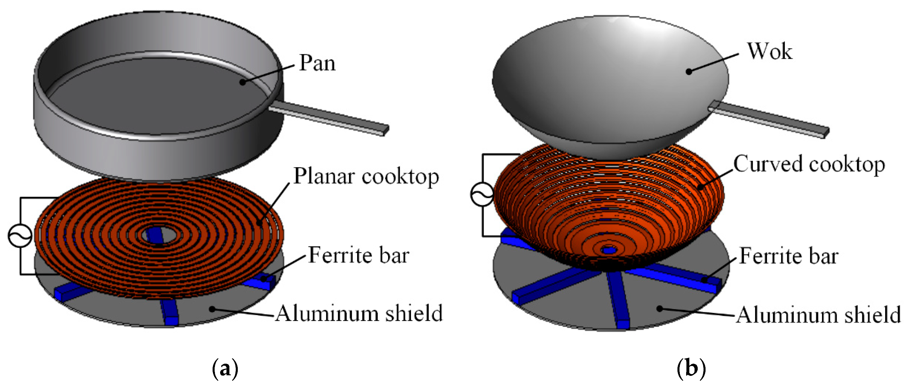
Currently, as shown in
Figure 1a,b, the primary cooktop for induction heating needs to be specifically designed as a planar cooktop and a curved cooktop to heat flat-bottom pans and convex-bottom woks, respectively. This specific arrangement significantly limits the utilization of cookware. Inevitably, customers are required to install various induction cookers in order to use different cookware for different cooking styles. The purpose of this paper is to propose and implement an all-in-one induction heating system for different utensils, including both flat-bottom pans and convex-bottom woks. The key is to introduce a detachable frustum cooktop and to adopt dual magnetic couplings so as to effectuate the desired heating performance.
In
Section 2, the proposed induction heating system and its principle of operation is described. Then, the theoretical modeling of the proposed system is derived in
Section 3, with emphasis on the functionality of the frustum coil.
Section 4 is devoted to the computational simulation of the proposed system, including the magnetic flux density, eddy-current density and Joule loss density distributions. In
Section 5, an experimental prototype is constructed and tested so as to further validate the feasibility of the proposed all-in-one induction heating. Finally, a conclusion is drawn in
Section 6.
2. Proposed Induction Heating System
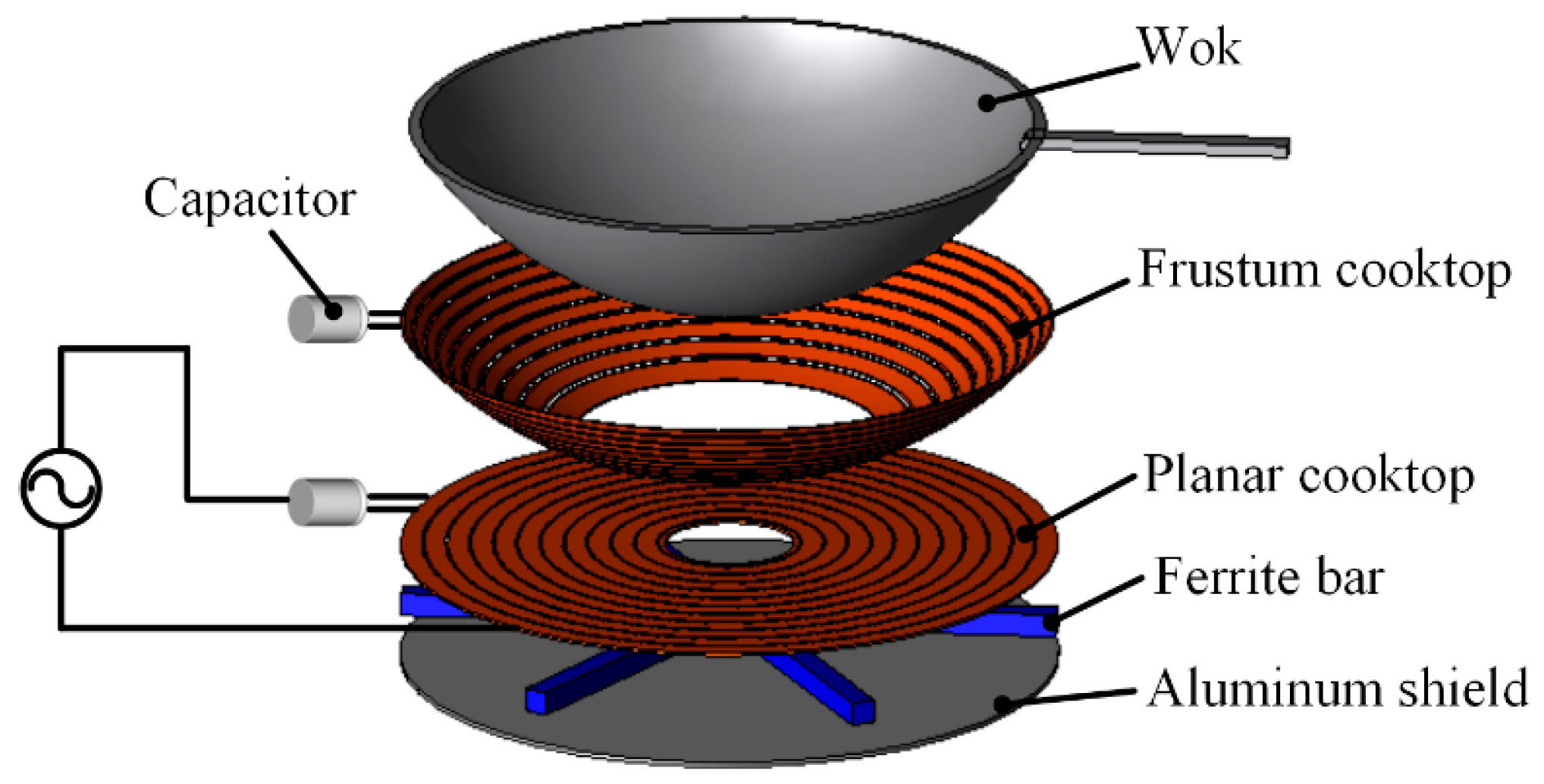
Figure 2 shows the configuration of the proposed induction system, which consists of a planar cooktop and a detachable frustum cooktop, both of them tuned at the same resonant frequency. When heating a flat-bottom pan, the frustum cooktop is detached; whereas when heating a convex-bottom wok, the frustum cooktop is employed to artfully heat the outer part of the wok. Additionally, the use of the frustum shape can help hold woks of different sizes. Since the principle of the induction heating for a flat-bottom pan using a planar cooktop has been widely discussed, the following discussion will focus on the wok heating using a planar cooktop together with a detachable frustum cooktop.
The principle of operation of the proposed induction heating system is based on dual magnetic coupling mechanisms, namely magnetic inductive coupling (MIC) and magnetic resonant coupling (MRC). Firstly, a high-frequency power supply or a resonant inverter [
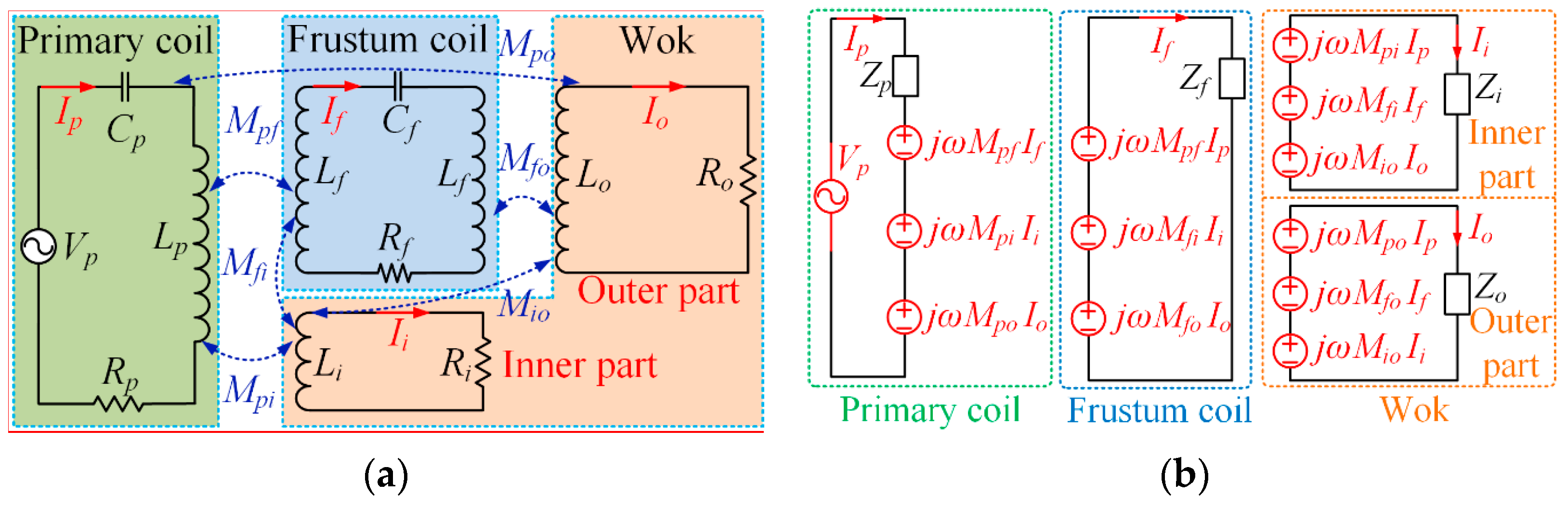
24] with an operating frequency ranging from 20 to 100 kHz serves to energize the primary coil. Then, it induces the resonant current to flow in the frustum coil via MRC, and the eddy current mainly flows in the inner part of the wok via MIC. Meanwhile, the frustum coil further induces the eddy current to mainly flow in the outer part of the wok. In order to theoretically analyze the proposed system, an equivalent circuit was established as depicted in
Figure 3, where
Lp,
Lf,
Li and
Lo are the self-inductances of the primary coil, frustum coil, inner part of the wok and outer part of the wok, respectively;
Rp,
Rf,
Ri and
Ro are the corresponding internal resistances, respectively;
Cp and
Cf are the compensated capacitors connected in series with the primary coil and frustum coil, respectively. All mutual inductances through magnetic couplings, namely,
Mpf,
Mpi,
Mfi,
Mpo,
Mfo and
Mio, are considered in the model. It should be noted that the ferrite bars and aluminum shield are ignored because they would cause unnecessary complication in the equivalent circuit while the corresponding effect on improving the magnetic field strength is somewhat compensated by the magnetic field leakage.
According to
Figure 3a, the impedances of the primary coil, frustum coil, inner part of the wok and outer part of the wok are denoted as:
By referring the impedances of the inner and outer parts of the wok to the frustum and primary coils, the equivalent circuit of
Figure 3a can be depicted as
Figure 3b so as to derive the decoupled circuit for the sake of easy calculation. Thus, the system equation can be expressed as:
Accordingly, the currents in the primary coil and frustum coil as well as in the inner and outer parts of the wok can be obtained as:
where
Here,
Ip and
If are currents in the primary coil and frustum coil, respectively;
Ii and
Io are the induced eddy currents in the inner part and outer part of the wok, respectively. In order to effectively transfer power from the primary coil to the frustum coil through a large air gap, it is necessary to ensure that both the primary and frustum coils work at the same resonant frequency, as given by:
According to (1) and (5), the inductances of the primary and frustum coils are fully compensated by their capacitances. Thus, the impedances
Zp and
Zf can be regarded as the pure resistances
Rp and
Rf, respectively:
Generated by the eddy current, the heating effect is mostly concentrated in a peripheral layer of the skin depth
δ, which can be obtained as:
where
f is the resonant frequency;
σ is the electrical conductivity;
μr and
μ0 are the relative permeability and vacuum permeability, respectively.
For easy calculation, the wok can be regarded as a spherical cap, which is a portion of a sphere cut off by a plane. Since the equivalent resistance of a vessel can be determined by the skin effect of the eddy current, then the resistances of the inner and outer parts of the wok can be expressed as:
where
Si and
So are the surface areas of the inner and outer parts of the wok and are equal to 2
πRE′ and 2
πR(
E −
E′), respectively;
R is the radius of the wok;
E′ and
E are the vertical heights of the inner part and outer part of the wok, respectively.
Therefore, by substituting (7) into (8), the equivalent resistances of the wok inner and outer parts can be expressed as:
By measuring the equivalent impedances of the primary and frustum coils under different conditions, the parameters in (2) can be quantitatively calculated and defined. In particular, the equivalent impedances of the primary coil itself, with the wok only and with both the frustum coil and the wok are
Zp,
Zpw and
Zpfw, respectively.
where
Similarly, the equivalent impedances of the frustum coil itself, with the wok only and with both the primary coil and the wok are
Zf,
Zfw and
Zfwp, respectively.
where
Accordingly, the six unknown variables, namely,
Li,
Lo,
Mpi,
Mpo,
Mfi and
Mfo, can be calculated based on the six equations listed in (10) and (12). The key terms of the proposed induction heating system are shown in
Table 1.
Based on (3) and (4), it can be found that the eddy currents Ii and Io are induced via both MIC and MRC mechanisms in the inner and outer parts of the wok, respectively. However, the eddy current Ii is mainly caused by the MIC mechanism because of the large Mpi, which is governed by the short distance between the primary coil and the inner part of the wok. Thus, there is no need to add an intermediate resonant coil to heat the inner part of the wok. On the contrary, the eddy current Io mainly depends on Mpf and Mfo or the MRC mechanism because of the small Mpo, which is determined by the large distance between the primary coil and the outer part of the wok. Mpf denotes the coupling strength between the primary coil and the frustum coil, while Mfo determines the coupling strength between the frustum coil and the outer part of the wok.
Moreover, the transmission efficiency of the proposed system can be calculated by:
where
Pout is the dissipated power in the wok;
Pin is the input power from the inverter;
φ is the phase angle between the input voltage
Vp and current
Ip.
Because of the MRC mechanism of the frustum coil, both Mpf and Mfo are significantly improved to induce the desired the eddy current. As a result, the proposed all-in-one induction heating system can effectively heat both the inner and outer parts of the wok by using a planar primary coil and a detachable frustum coil.
3. Theoretical Modeling
Given that the operating frequency of the induction heating system is around 20–100 kHz, the quasi-static approximation is employed for mathematical modeling. The geometric model of the wok, which can be regarded as a part of the spherical surface with the radius
R, can be built in the cylindrical coordinate, and its cross-section along the sphere diameter can be built in the orthogonal coordinate as shown in
Figure 4. In the figure,
E stands for the vertical height and
D the horizontal radius of the wok, while the angle from the wok edge to the bottom center is
θ. The wok is virtually divided into two parts, namely the inner part and outer part, which cover one third and two thirds of the horizontal diameter, respectively. The size of the primary coil size is selected by taking into account the effective heating for all wok areas while avoiding unexpected magnetic leakage. The size of the frustum coil is determined with the consideration of fully boosting the poor heating performance of the outer part of the wok and achieving a more uniform thermal distribution of the wok. All critical parameters of the wok model are given in
Table 2.
Consequently, the point on the edge of the wok inner part can be expressed by the corresponding arc angle
θ′, horizontal radius
D′ and vertical height
E′, as given by:
where
e,
g and
d are the wok and ceramic glass thicknesses and the vertical wok thickness, respectively.
According to the Maxwell equations, the relationship between the magnetic flux density
B and the induced eddy current
jωσA is given by:
where
ω and
A are the operating frequency and magnetic vector potential in the wok, respectively;
Jsource is the applied current density in the coil. In order to assess the importance of the frustum coil, the theoretical modeling is separately realized with and without the use of the frustum coil.
3.1. Without Frustum Coil
When the wok is heated directly by a planar primary coil without the frustum coil, the geometric model is depicted in
Figure 5, where the magnetic flux density
B1 at an arbitrary point
N (
rie,
zie) on the wok outside surface (the curved red line) is the point of interest. The inner and outer radii of the planar primary coil are
rpi and
rpo, respectively. The parameter
lie represents the vertical distance between the coil and the wok outside surface at the point of interest, which varies from
lmin to
lmax as follows:
Accordingly, following the process of derivation in [
15], the magnetic vector potential at the point of interest in the cylindrical coordinate produced by a single-turn coil located at
P (
ri,0) of the planar primary coil can be expressed as:
where
Ip is the primary current;
k is the integration variable;
J1(
kr) is a Bessel function of the first kind and order one;
k1 represents (
k2 +
jωμ0μrσ)
1/2. Hence, the magnetic flux density at the point of interest produced by the planar primary coil having
n turns can be obtained as:
3.2. With Frustum Coil
As mentioned above, the proposed induction heating system incorporates a detachable frustum coil to help heat the wok. For the inner part of the wok, the wireless power is mainly transferred using the MIC mechanism due to the short transfer distance. For the outer part of the wok, the wireless power is mainly transferred using the MRC mechanism in the presence of a large air gap. The geometric model is depicted in
Figure 6, where the magnetic flux density
B2 at an arbitrary point
N (
rje, zje) on the wok outside surface (the curved red and blue lines) is the point of interest. There are two scenarios: The point of interest is below the specified single-turn coil (
zj >
zje), as shown in
Figure 6a, or the point of interest is above the specified single-turn coil (
zj ≤
zje), as shown in
Figure 6b. For the first scenario,
zje is a negative value, and the magnetic vector potential at the point of interest produced by a single-turn coil located at
Q (
rj,
zj) of the frustum coil can be derived as:
where
If denotes the current in the frustum coil that was calculated in
Section 2.
For the second scenario,
zje is a positive value, and the magnetic vector potential at the point of interest can be derived as:
Assuming that the number of turns of the primary coil is np and the number of turns of the frustum coil is
nf, the magnetic flux density at the point of interest along the outer surface of the wok can be obtained as
4. Computational Simulation
As the finite element method (FEM) has been widely accepted for numerical analyses, the FEM-based software package JMAG was adopted to simulate the electromagnetic field and hence the eddy current loss. In order to achieve the desired heating performance while maintaining high transfer efficiency and low electromagnetic interference, the operating frequency was set to 40 kHz. The key parameters of the proposed heating system for both theoretical calculation and computational simulation are listed in
Table 2. It should be noted that the ferrite bars and aluminum shield were taken into account during simulation.
Firstly, the magnetic flux distributions without and with the frustum coil were simulated as shown in
Figure 7. When there is no frustum coil attached beneath the wok, it can be observed that a large amount of magnetic flux does not couple with the outer part of the wok owing to the corresponding large air gap. Such severe magnetic field leakage and weak magnetic coupling inevitably deteriorate the heating performance. On the contrary, when equipped with the frustum coil, the magnetic flux can couple effectively with both the inner and outer parts of the wok. Moreover, it can be observed from
Figure 7c,d that the frustum coil utilizes the MRC mechanism to significantly strengthen the magnetic coupling of the outer part of the wok, while suppressing the magnetic field leakage. The potential magnetic interference can be further reduced by properly shortening the outer radius of the frustum coil and adding shielding around the wok edge.
In order to accurately determine the parameters of the frustum coil and exhibit the enhanced magnetic coupling effect, the simulated results of the magnetic flux density along the wok surface without and with the frustum coil were compared with the analytical results from
Section 3, as shown in
Figure 8. Particularly, the calculated lines were obtained by moving points mentioned in (20) and (23) along the wok’s curved bottom. The slight discrepancy was mainly due to the inevitable magnetic field leakage, as well as the effect of the ferrite bars and aluminum shield. Because of the ferromagnetic property of the wok, the magnetic flux flowed along the wok surface to form a closed path. Thus, as depicted in
Figure 8, the magnetic flux density at the center of the wok was almost zero, which can also be observed from the magnetic flux distributions shown in
Figure 7.
Focusing on
Figure 8a, it can be observed that the magnetic flux density exhibited two peaks at the two ends of the inner part, but dropped dramatically at the outer part of the wok. Taking the magnetic flux density of 5.9 mT at the two ends of the inner part as the expected value, the number of turns of the frustum coil can be designed to meet this expected magnetic flux density:
where
Bexpected(
r,
z),
B1(
r,
z) and
B2(
r,
z) are the expected, original and compensated magnetic flux densities along the wok, respectively.
In order to ensure that the magnetic flux density in the outer part of the wok is effectively boosted above the expected line and to prevent uneven thermal distribution caused by too many coil turns, the turn number of the frustum coil should be carefully designed. Thus, the turn number of the frustum coil was calculated to be 40 according to (24) and the key parameters listed in
Table 1 and
Table 2. As a result, after being equipped with the frustum coil, the magnetic flux density in the wok is as shown in
Figure 8b.
To assess the effectiveness of the heating performance produced by the frustum coil, the average eddy current density in the surface of the wok was numerically computed. As depicted in
Figure 9a, without using the frustum coil, the planar primary coil can only produce a lower eddy current density concentrating on a small ring area in the inner part of the wok while the outer part of the wok involves much less eddy current density. In contrast, as depicted in
Figure 9b, after utilizing the artfully designed frustum coil, the proposed induction heating effectively enlarges the area of high eddy current density to both the inner and outer parts of the wok. This improvement was attributed to the proposed dual magnetic couplings, namely the MIC and MRC mechanisms. Moreover, the Joule loss density could be readily obtained from the simulation and directly related to the heating performance, which was adopted and analyzed under different operating frequencies as shown in
Figure 10. When the operating frequency was 37 kHz, which is lower than the resonant frequency of 40 kHz, it was found that the thermal effect was relatively poor with a maximum value of 5.17 × 10
7 W/m
3 and an average value of 3.78 × 10
7 W/m
3. On the other hand, when the operating frequency was 43 kHz, which is higher than the resonant frequency, the Joule loss density concentrated on the inner part and a small ring area of the outer part of the wok. The corresponding maximum and average Joule loss densities were 7.31 × 10
7 and 4.41 × 10
7 W/m
3, respectively. As expected, when the system was operated at the resonant frequency, the maximum and average Joule loss densities were 7.94 × 10
7 and 5.67 × 10
7 W/m
3, respectively, which are higher than those of other operating frequencies. This confirms that the proposed induction heating is capable of enhancing the thermal performance by regulating the operating frequency at the resonant frequency. Moreover, the high uniformity of thermal distribution at the resonant state can avoid the fast aging of the wok and improve its heating quality.
5. Experimental Verification
In order to verify the proposed induction heating, a prototype was built for experimentation. The testing setup is shown in
Figure 11, in which the AC power source was provided by a full-bridge inverter, the DC source of the inverter was provided by a high-power DC supply (Kikusui PWR1600M), the current was measured by current probes (Tektronix TCP A300), the temperature was measured by a thermal probe (NI USB-TC01) and recorded by the LabVIEW, the thermal image was captured by a noncontact thermal scanner (Fluke TiS40), the power factor and power were measured by a power analyzer (Voltech PM300) and all waveforms erre recorded in an oscilloscope (Lecroy 6100A). The resonant frequency was set at 40 kHz and the ambient temperature was 20 °C. For experimentation, the frustum coil was temporarily fixed by sticky tape and adhesive for the sake of experimental convenience. In future, it should be fixed by thermally adhesive coating with a sleeve. The corresponding compensation capacitor can be embedded inside the sleeve during the production stage so that it will become more practical and compact for commercialization.
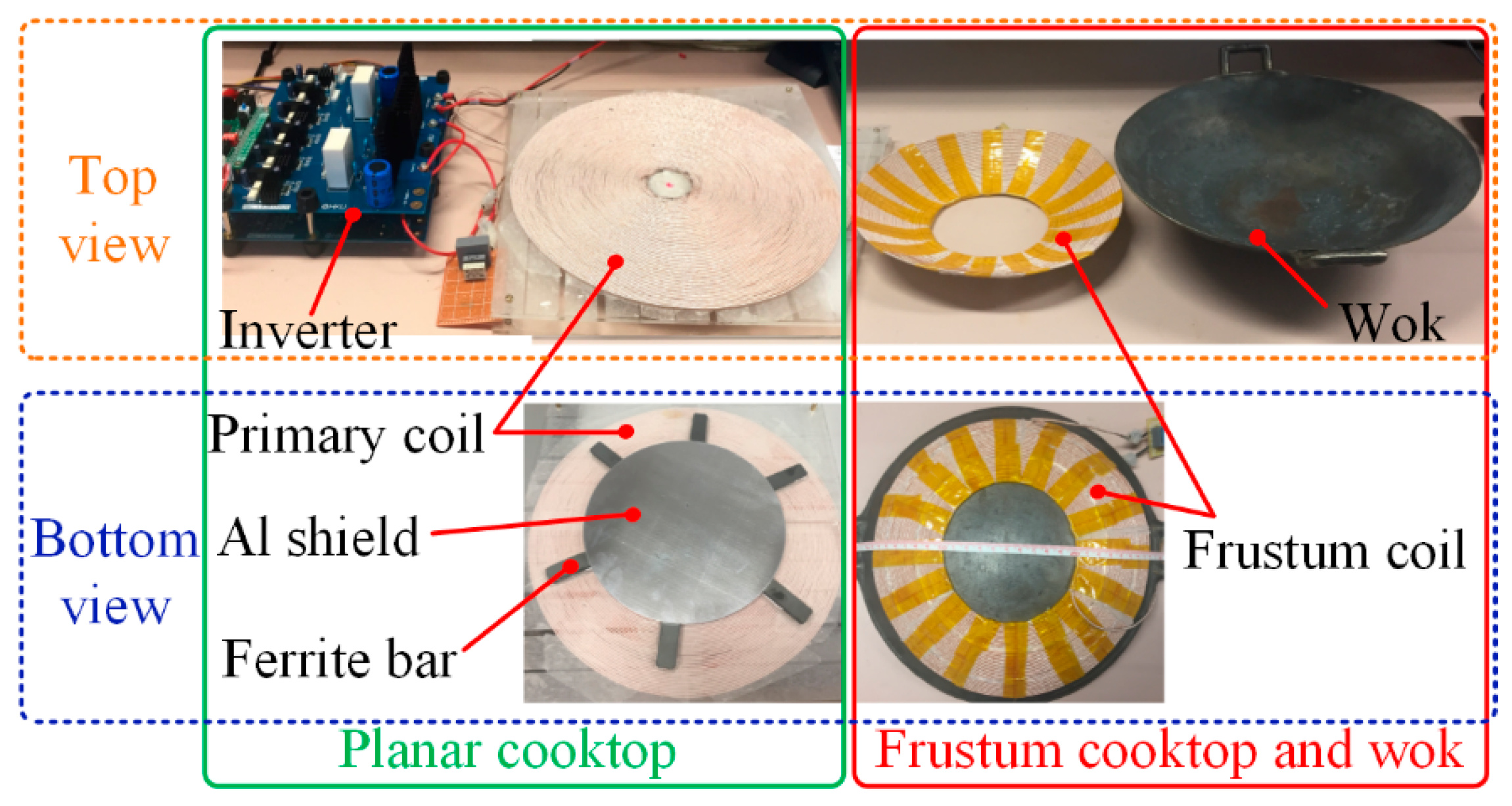
In addition,
Figure 12 shows the detailed construction of the prototype. For experimentation, the frustum coil was simply fixed using heat-resistant tape. In future, it will be coated by heat-resistant resin to protect the coil and increase the structural strength. Meanwhile, six ferrite bars and an aluminum shield were adopted under the primary coil so as to improve the magnetic field strength and reduce the magnetic field leakage, respectively. The wok was purposely kept empty to facilitate accurate temperature measurement using a thermal scanner.
To analyze the system response when operating at the resonant and non-resonant states, the input phase angle and power factor are shown in
Figure 13a, while the calculated and measured root-mean-square (RMS) currents are shown in
Figure 13b. When the operating frequency was at the resonant frequency, it was found that the phase angle and power factor reached the minimum value of 8.7° and the maximum value of 0.988, respectively. In addition, the measured results of the primary and frustum coil currents agree well with the calculated results obtained from (3) and (4), as shown in
Figure 13b. Namely, the inductor was fully compensated by the capacitor so that the MRC mechanism was achieved to maximize the power factor and currents at the resonant frequency. It should be noted that the measured results are slightly higher than the calculated results because the ferrite bars and aluminum shield were neglected in the calculation.
Meanwhile, the input power as well as the primary and frustum coil currents can be flexibly adjusted with a wide range by simply changing the input voltage. Specifically, the simulated and calculated
Ip and
If under different input voltages are shown in
Figure 14a. The trend of the calculated current is in good agreement with the simulated current while the values are slightly lower due to the fact that the ferrite bars and aluminum shielding were neglected. As shown in
Figure 14b, when the value of
Vp was varied from 20 V to 140 V, the input power increased from 20 W to 1500 W while the primary (frustum) coil RMS current increased from 0.97 A (1.26 A) to 10.73 A (12.12 A). Thus, when
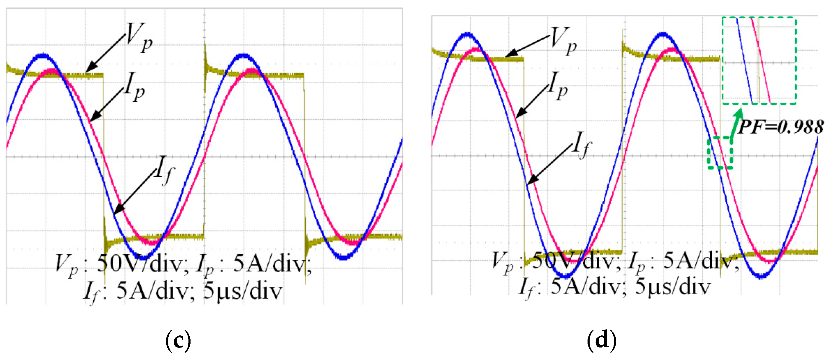
Vp was set at 20 V, 60 V, 100 V and 140 V, the waveforms of
Vp,
Ip and
If at the resonant frequency were measured as shown in
Figure 15. The corresponding RMS values of
Ip (
If) were 0.97 A (1.26 A), 3.58 A (4.42 A), 7.34 A (8.46 A) and 10.73 A (12.12 A), respectively. Also, as shown in
Figure 15d, the
Vp and
Ip waveforms are almost in phase due to the LC resonance, which not only caused the high-power factor of 0.988, but also helped to reduce the switching loss. Therefore, the system efficiency at the rated power of 1500 W was calculated to be equal to 96.75%.
In order to verify the effectiveness of the frustum coil and hence the MRC mechanism in the proposed induction heating, the wok was heated for 180 s without and with the frustum coil at the power rating of 1500 W. Then, the temperatures of nine evenly distributed points along the wok surface diameter were measured by the thermal probe. Throughout the whole heating period, the temperatures were sampled every 20 s. When the wok was heated without the frustum coil, it was observed (
Figure 16a) that only a small area near the center was heated up while the outer part of the wok was poorly heated. In particular, the temperature of the wok inner part reached over 70 °C with a maximum temperature of 85.5 °C at 180 s. However, the temperature of the wok outer part was comparatively low with a minimum temperature of 35.2 °C. When the wok was heated with the frustum coil, it was observed (
Figure 16b) that fast heating and uniform temperature distribution could be achieved both in the inner and outer parts of the wok. In particular, the temperature of the wok inner part reached over 105 °C with a maximum temperature of 105.9 °C at 180 s. What is more, the temperature of the wok outer part was remarkably improved and reached above 95 °C. Hence, the overall heating performance was significantly increased while the temperature difference was hugely reduced by the proposed system.
Finally, the entire heating effect of the proposed induction heating system equipped with the frustum coil was assessed. Specifically, the dissipated power in the primary coil, frustum coil and the wok were 27.63, 20.56 and 1435.98 W, respectively. The wok inner part is mostly heated by the primary coil with the MIC mechanism and the wok outer part is mainly heated by the frustum coil with the MRC mechanism. Thus, a homogenous power density can be generated to achieve an even temperature distribution. The corresponding thermal images of the wok after heating for 180 s are captured as shown in
Figure 17. Specifically, the temperatures of the selected nine evenly distributed points along the wok surface diameter varied between 105.3 °C and 93.6 °C, as depicted in
Figure 17a, which agree well with the data shown in
Figure 16b. In addition, as depicted in
Figure 17b, the temperatures of five evenly distributed points along the wok vertical height varied between 108.8 °C and 93.8 °C. This indicates that the heating performance of the wok along the vertical direction was as effective as that along the horizontal direction. Therefore, the experimental results well agree with the theoretical analysis and computational simulation, verifying the heating performance of the proposed induction heating.
6. Conclusions
In this paper, an all-in-one induction heating system was proposed and implemented, which is capable of effectively heating both flat-bottom pans and convex-bottom woks based on a planar cooktop. The key is to utilize a detachable frustum cooktop, which is actually a frustum coil coated with heat-resistant resin. Thus, the proposed system functionally combines the conventional planar cooktop and curved cooktop together while bringing dramatic convenience for cooking utensils with different shapes, which is absent in the literature.
Focusing on heating the wok, which is much more demanding than heating the pan, the frustum coil serves to provide the MRC mechanism to boost the magnetic coupling of the outer part of the wok with a large air gap. Meanwhile, the inner part of the wok with a small air gap is heated by the MIC mechanism. The number of turns of the frustum coil can be properly calculated so that the system not only heats a curved-bottom wok successfully, but also achieves a relatively uniform thermal distribution along the wok. Specifically, the theoretical models of the proposed induction heating system with and without using the frustum coil are derived to analyze the proposed system. Based on the FEM-based software package JMAG, a computational simulation of the proposed system was provided to elaborate the heating performance of the wok. After fabricating a prototype with the maximum delivering power of 1500 W, a series of experiments was performed. The calculated, simulated and experimental results are all in good agreement, thus validating the feasibility of the proposed induction heating system.


