Article

Active Control of Drive Chain Torsional Vibration for DFIG-Based Wind Turbine

1
School of Mechanical and Electrical Engineering, Shihezi University, Xinjiang 832007, China
2
School of Electrical Engineering, Chongqing University, Chongqing 400032, China
*
Author to whom correspondence should be addressed.
Energies 2019, 12(9), 1744; https://doi.org/10.3390/en12091744
Submission received: 2 April 2019 / Revised: 29 April 2019 / Accepted: 5 May 2019 / Published: 8 May 2019
(This article belongs to the Special Issue Design, Fabrication and Performance of Wind Turbines 2019)

Abstract

:
Due to the fast electric control of the doubly-fed induction generator (DFIG) when experiencing power grid disturbance or turbulent wind, the flexible drive chain of the wind turbine (WT) generates long-term torsional vibration, which shortens the service life of the drive chain. The torsional vibration causes fatigue damage of the gearbox and affects power generation. In this paper, a two-channel active damping control measure is proposed. The strategy forms a new WT electromagnetic torque reference value through two channels: one is a proportion integration differentiation (PID) damping term with frequency difference, which is used to reduce torsional vibration caused by frequency difference between fan and shafting; the other adopts the torsional vibration angle (θs) as the feedback signal, and an additional damping term is formed by bandpass filter (BPF) and trap filter (BRF). The strategy can increase the electromagnetic torque and suppress the torsional vibration of the drive chain. Finally, modeling and simulation using MATLAB/Simulink show that the method can effectively suppress the torsional vibration of the drive chain without affecting power generation.

1. Introduction

Wind power generation has been growing rapidly throughout the world in recent years, and the doubly-fed induction generator (DFIG) has become a mainstream wind turbine (WT) [1]. Due to the harsh environment of the WT and severe impact load, the failure rate of the WT is higher than other industrial fields; one of the serious problems is torsional vibration on the WT shaft [2]. Torsional vibration can cause significant stresses and fatigue loss of gearbox. In addition, torsional vibration of the mechanical components can be transmitted to electrical power oscillations, leading to potential resonances between WT and the power system. In severe cases, the WT will be damaged and lead to grid faults [3]. It can be seen that torsional vibration of the drive chain not only directly affects the safe operation of the WT, but also the stability of the network system. Therefore, reducing torsional vibration of the drive chain is particularly important and urgent.
In recent years, some scholars have done some research on control of the WT drive chain. Among other things, researchers studied the following: control of the DFIG by controlling the active and reactive power [4,5]; the control strategy under the grid fault of WT [6,7,8]; suppression of the torsional vibration by controlling the mechanical torque of the drive chain through pitch angle [9,10,11,12]; control of torsional vibration based on Small-Signal Analysis [13]; electromechanical oscillation damping [14]; and using the variable pitch system and converter as actuators to reduce the dynamic load of the WT to suppress torsional vibration of drive chain [15]. Although these methods have played a certain role in increasing damping and reducing torsional vibration, most of the research was on cases of grid faults or mechanical torque, and involve little about long-term low-amplitude and low-frequency torsional vibration of the drive chain during normal operation of the grid.
Based on the work of predecessors, this paper proposes a novel active control strategy to reduce the torsional vibration of the drive chain during normal operation of power grid. Since the inertia of the generator is much smaller than that of the WT, the dynamic change of the electromagnetic torque is more likely to cause severe vibration of the drive chain than the aerodynamic torque. Therefore, controlling the electromagnetic torque is the key to reducing torsional vibration of the drive chain and improving the reliability of the WT. In this paper, a two-channel active damping control measure is proposed, achieving the purpose of suppressing torsional vibration of the drive chain under the premise of ensuring the output power of the unit is stable.

2. Modeling of Wind Turbine

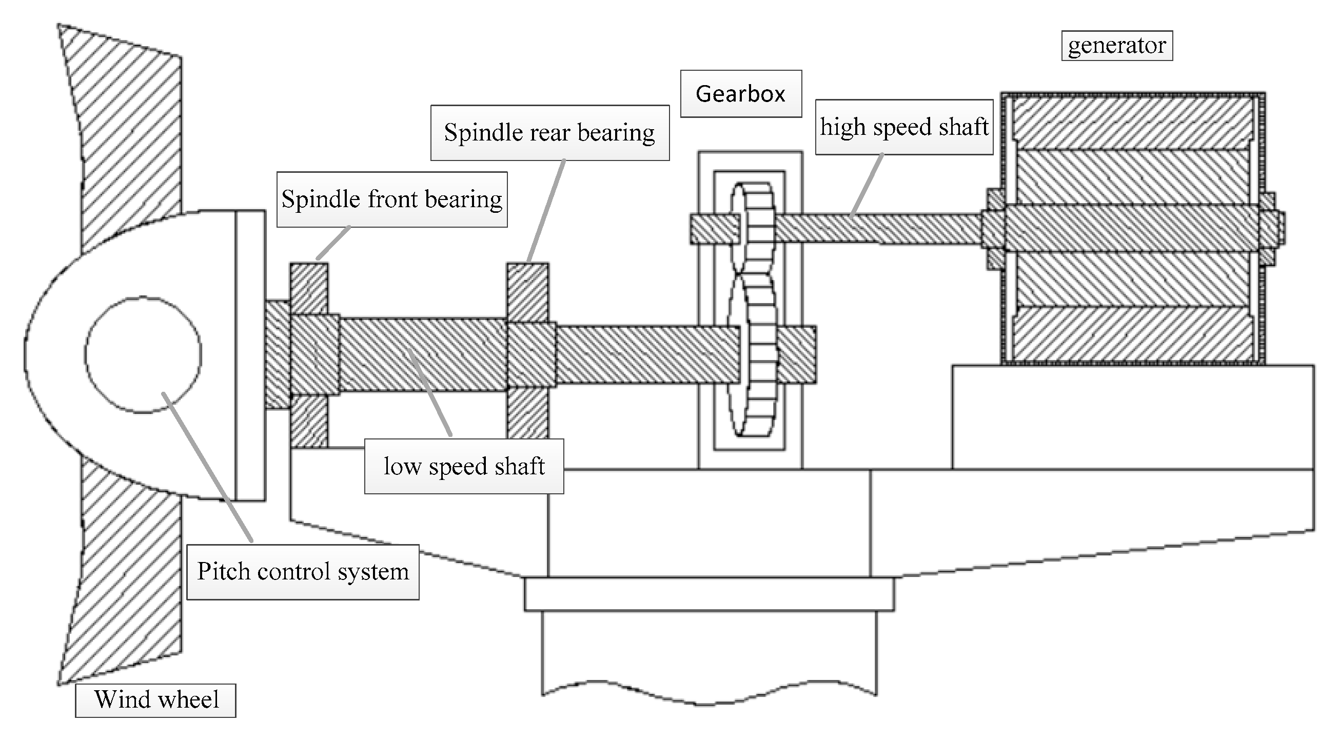
2.1. Structure of Wind Turbine

The drive chain of the doubly-fed WT studied in this paper is mainly composed of wind wheel, pitch control system, spindle front bearing, low speed shaft, gearbox, high speed shaft, generator, etc. (as shown in Figure 1). The mechanical energy absorbed by the wind wheel is transmitted to the gearbox through the low-speed shaft, and the high-speed shaft connects the high-speed output terminal of the gearbox with the generator. At the same time, the drive chain transfers the load to the tower barrel through the chassis and yaw system.

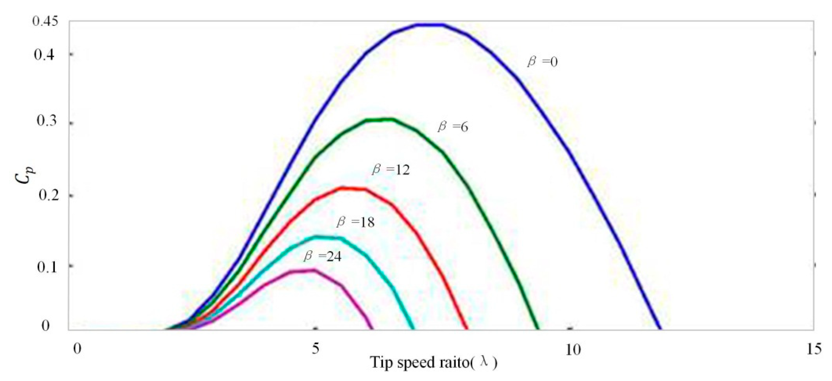
2.2. Modeling of the Wind Wheel

The mathematical relation for the mechanical power extraction from the wind can be expressed as follows [16,17]:
P m = 1 2 C p ( λ , β ) ρ π R 2 V 3
T t = P m ω m = 1 2 A ρ V 2 C p ( λ , β ) R λ
where Pm is the mechanical power (W) from the wind, Tt is the mechanical torque (N·m), ρ is the air density (kg/m3), A is the swept area by the WT rotor (m2), R is the blade radius (m), V is the wind speed (m/s), and Cp is the power coefficient (or performance coefficient), tip speed ratio is λ (ωm·R/V), and blade pitch angle is β (deg), ωm is the angular speed of the WT(rad/s). The Cp curves [18] were calculated for different tip speed ratio (λ) and different blade pitch angle (β). The Cpλ curves are shown in Figure 2.
The power coefficient (Cp) indicates how efficiently the conversion of wind power to rotational mechanical power is performed by the WT. The Betz limit is the maximum theoretic value reached by the power coefficient which is 0.59 for three blades horizontal axis WT (a more complete discussion can be find in [18]). The Cp curves are obtained experimentally by the manufactures following international rules.
In more generic analysis, the Equations (3) and (4) can be used to model the dynamics of the Cp. The values of C1C9 presented in Table 1 were suggested by Slootweg to represent the aerodynamics of a modern WT [19].
C p ( λ , β ) = C 1 · ( C 2 λ i C 3 · β C 4 · β C 5 C 6 ) · e C 7 λ i
λ i = 1 1 λ + C 8 · β C 9 β 3 + 1

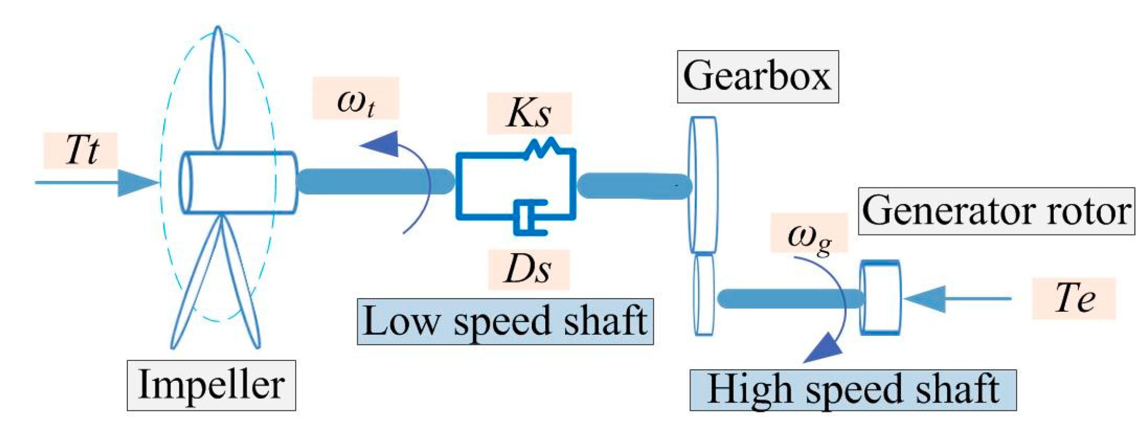
2.3. Drive Train Modeling

The impeller and generator rotor of a doubly fed WT are usually connected by a gearbox. Due to the existence of the gearbox, the flexibility of the entire shafting system is increased. In this paper, a two-mass model is used to simulate the flexible drive train system of a WT, which can accurately reflect torsional vibration of the drive chain. The two mass block shafting model equates impeller and hub as one mass block, and generator and gearbox as one mass block; the basic principle diagram is shown in Figure 3.
The WT low-speed shaft is converted to the high-speed side of the generator rotor by the gearbox, and the variables and parameters are still expressed by the symbols before the conversion. The mathematical model of the two-mass drive chain motion equation is as follows [20]:
{ J t d ω t d t = T t ( k s θ s + D s ( ω t ω g ) ) J g d ω g d t = ( k s θ s + D s ( ω t ω g ) ) T e d θ s d t = ω t ω g
where Jt, Jg are the inertia of the impeller and the generator rotor (including the gearbox); ωt and ωg are angular velocity of impeller and generator rotor; Tt and Te are mechanical torque and electromagnetic torque of WT; θs is the torsion angle of the drive chain; Ds and Ks are damping coefficient and stiffness coefficient of drive chain, respectively.
Simplified (5) can obtain (6):
J t J g J t + J g d 2 θ s d t 2 + D s d θ s d t + K s θ s = J g T t + J t T e J t + J g
Equation (6) is the differential equation of motion of the drive chain system, which can establish the state space equation of the drive chain based on the lumped mass method [20]:
[ d 2 θ s d t 2 d θ s d t ] = [ ( J t + J g ) D s J t J g ( J t + J g ) K s J t J g 1 0 ] · [ d θ s d t θ s ] + [ 1 J g 1 J t 0 0 ] · [ T e T t ]
d ω g d t = [ D s J g K s J g ] · [ d θ s d t θ s ] T e J g
In the Equations (7) and (8), the Te is used as the control input, the Tt of the wind wheel is regarded as the disturbance input.

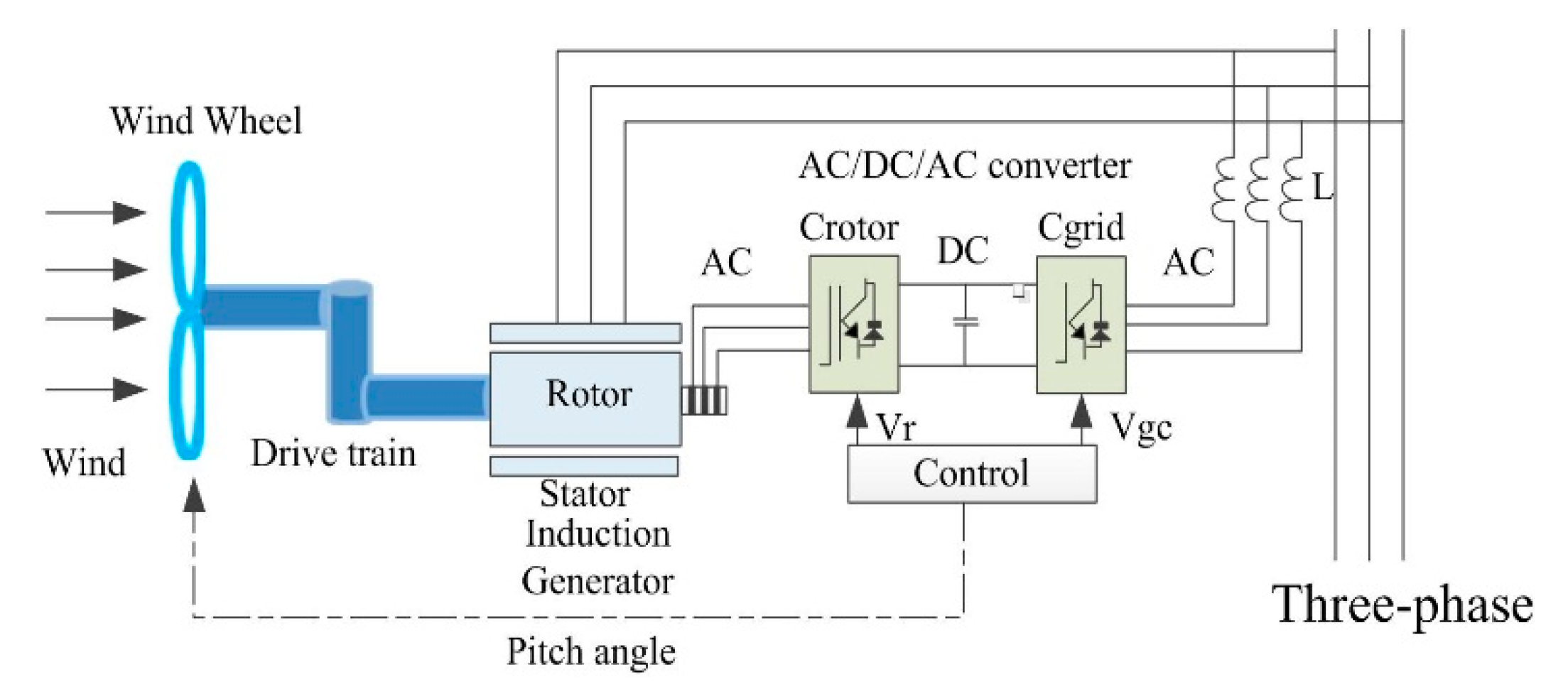
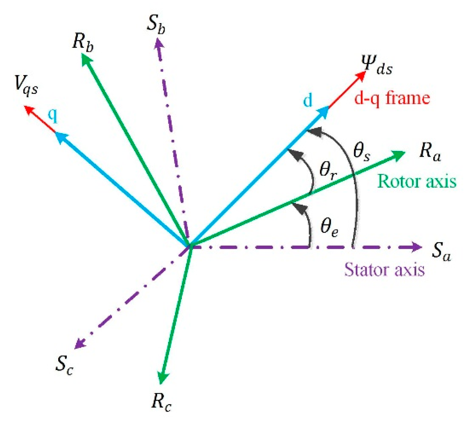
2.4. Dynamic Model of the DFIG

The generator stator of the doubly-fed WT is directly connected to the grid, and the generator rotor is connected to the grid through the back-to-back converter [21] (as shown in Figure 4). The mathematical model of doubly-fed generator in two-phase rotation coordinate system (d-q frame) is studied and oriented the stator flux [22] (ϕsd = ϕs ϕsd = ϕs; ϕsq = 0 ϕsq = 0).
The classical electrical equations of the DFIG in the Park frame are addressed in [23], Lennart [23] and Tapia [24] given as follows:
{ d φ s d d t = V s d R s i s d + φ s q ω s d φ s q d t = V s q R s i s q φ s d ω s d φ r d d t = V r d R r i r d + φ r q ω r d φ r q d t = V r q R s i s q φ r d ω r
where the stator and rotor angular velocities are linked by the following relation:
ω r = ω s ω
VsdVsq and VrdVrq are the stator and rotor d-q axes voltages, respectively; Rs and Rr are the stator and rotor phase resistances, respectively.
The stator and rotor flux can be expressed as follows:
{ φ s d = L s i s d + M i r d φ s q = L s i s q + M i r q φ r d = L r i r d + M i s d φ r q = L r i r q + M i s q
where L s = L f s + L m , L r = L f r + M 2 L m .
Where isdisq and irdirq are the stator and rotor d-q axes currents, respectively; φsdφsq and φrdφrq are the stator and rotor d-q axes fluxes, respectively; Ls, Lm, and Lr are the stator, magnetizing, and rotor inductances, respectively; The stator and rotor active and reactive powers are given, respectively, by Equations (12) and (13):
{ P s = 3 2 ( V s d i s d + V s q i s q ) Q s = 3 2 ( V s q i s d V s d i s q )
{ P r = 3 2 ( V r d i r d + V r q i r q ) Q r = 3 2 ( V r q i r d V r q i r q )
In the rotating field reference frame, the d-q orientation has to be synchronized with the stator flux [25] (see in Figure 5):
The electromagnetic torque is given by [26,27]:
T e = 3 2 p M L s ( i r d φ s q i r q φ s d )
where Te is electromagnetic torque; and p is number of poles. Basic equation of motion control systems is expressed as [28].
J d ω m d t + D ω m + K θ m = T e T m
with
d θ m d t = ω m
where J is the mechanical moment of inertia (kg·m2 kg·m2); ωm and θm are the mechanical angular speed of rotor (rad/s) and mechanical angle of rotor (rad), respectively; Te and Tm are the electromagnetic torque (N·m) and load torque (N·m), respectively; D and K are the resistance torque damping coefficient and torsional elastic torque coefficient, respectively.
Compared with other items, the damping torque and torsional elastic torque have less influence on the system. If the damping torque and torsional elastic torque are neglected, the basic equations of the motion control system can be simplified as follows:
J d ω m d t = T e T m
with:
d θ m d t = ω m
The objective of the control system is speed and angle of the motor. From Equations (15) and (16) can be seen, the only way to control the angle and speed is to control the electromagnetic torque of the motor. The control strategy proposed achieves the purpose of suppressing the torsional vibration of the drive chain by controlling the electromagnetic torque.

3. Active Control Approach

This paper proposed a new control strategy of torsional vibration during normal operation of the power grid. Based on proportion integration differentiation (PID) [29] control, the torsion angle (θs) is used as the feedback signal to increase the electromagnetic torque through the torsional load controller, and achieve the purpose of suppressing the torsional vibration under the premise of ensuring the output power of the unit is stable.

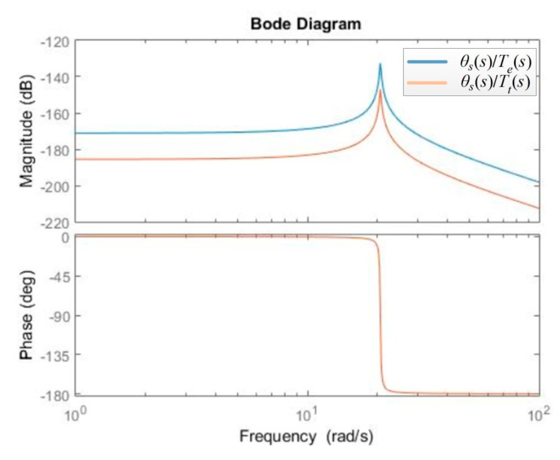
3.1. Characteristic Analysis of Torsional Vibration

According to the two-mass block model of the drive chain shown in Equation (5), the motion equation of the impeller relative to the angular displacement θs of the generator rotor can be obtained in [30]:
d 2 θ s d t 2 + D s ( 1 J t + 1 J g ) d θ s d t + K s ( 1 J t + 1 J g ) θ s = T t J t + T e J g
The above formula shows that θs moves in the form of second-order oscillation. The poles of the equation of motion are as follows:
λ 1 , 2 = ξ ω n ± j ω ξ
where, ω n = K s ( 1 J t + 1 J g ) is the natural oscillation frequency of drive chain, ξ = D s 2 K s ( 1 J t + 1 J g ) is the damping ratio of the drive chain, ω ξ = ω n 1 ξ 2 is the actual oscillation frequency after considering the system damping. It can be seen that the actual torsional vibration frequency of the drive chain is closely related to the parameters Ds, Ks, Jt, Jg of the system.
Through Formula (17), the transfer function with Tt and Te as input variables can be further derived, as shown in Formula (18) and (19).
θ s ( s ) T t ( s ) = 1 J t · 1 s 2 + 2 ξ ω n s + ω n 2
θ s ( s ) T e ( s ) = 1 J g · 1 s 2 + 2 ξ ω n s + ω n 2
Based on the transfer functions shown in Equations (18) and (19), the frequency domain characteristics of the drive chain from Tt and Te to θs can be obtained (as shown in Figure 6). It can be seen that whether the input quantity is electromagnetic torque disturbance or mechanical torque disturbance, the amplitude gain of the drive chain near the resonance frequency is very high, that is, both inputs can excite the drive chain torsional vibration. Meanwhile, it also can be seen the magnitude of the drive chain system with electromagnetic torque as input at the resonance frequency is larger than the mechanical torque, so the disturbance of electromagnetic torque will cause more serious torsional vibration.

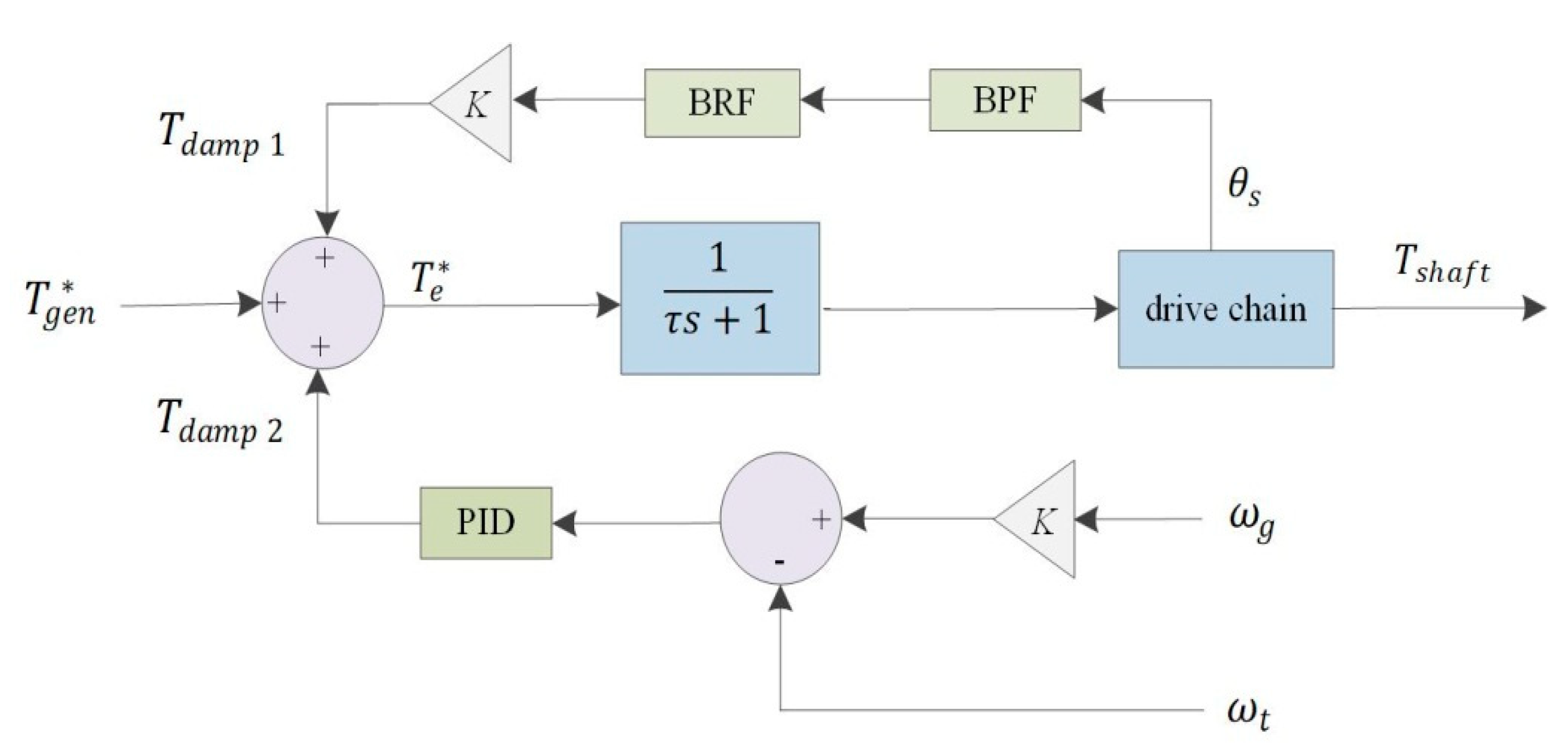
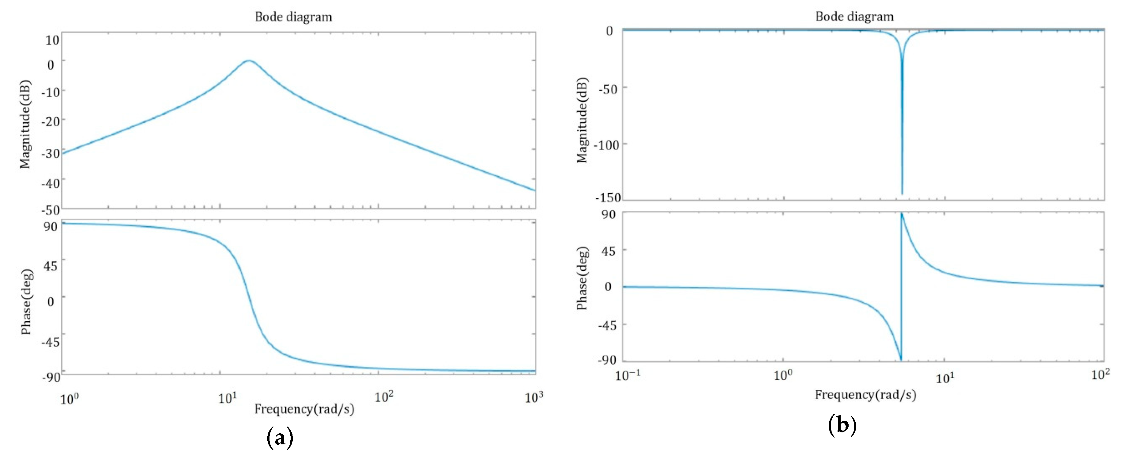
3.2. Control Principle of Drive Chain

On the basis of PID control, adding a torque feedback loop connected by a bandpass filter (BPF) and a trap filter (BRF) achieves two-channel active damping control, additional torques Tdamp1 and Tdamp2 are added near the natural vibration frequency of the drive chain. The main function of BPF is to produce ripple torque. The BRF is mainly to avoid the multi-section traversing frequency of wind wheel speed, such as 3P, 6P, and other frequencies. After the PID control, the deviation of the system is quickly and accurately eliminated, and the set value is restored, which makes the oscillation and deviation of the system smaller.
In the torsional vibration control of WT drive chain, the change of generator’s torque will have a great influence on its speed and output power. If the change of generator’s torque is too large, it may cause the instability of the system. So the Tdamp1 and Tdamp2 should be limited to a certain range, and then superimposed on the original torque reference value. Based on this principle, combined with the state space equation given in (7), the drive chain damping control strategy is shown in Figure 7.
It can be seen that the torque reference Te* contains three parts, as shown in the following equation:
T e * = T g e n * + T d a m p 1 + T d a m p 2
T g e n * is the given value of the torque control, Tdamp1 and Tdamp2 are the compensation electromagnetic torque. The Tdamp1 is obtained by series connection of a BPF and a BRF. The Tdamp2 is obtained by PID. The transfer functions between a BPF and a BRF are as follows:
G BPF ( s ) = K 2 ζ f ω s ( 1 + τ s ) s 2 + 2 ζ f ω s + ω 2
G BRF ( s ) = K ( s 2 + ω 2 ) s 2 + 2 ζ ω s + ω 2
In the formula, K is the control gain, ζf is the filter damping ratio, and ω is the center frequency. Sometimes, in order to compensate for the time lag in the design of the control system, a differential calculus (1 + τs) is added to the BPF, but the time constant τ is usually close to 0.
K = ( ζ t o t ζ 1 ) 1 J t + 1 J g
where
ζ = D s 2 K s 1 J t + 1 J g
In the formula, ζ (0.25 in paper) and ζtot are the inherent damping ratio of the drive chain system and the damping ratio after increasing the damping control, respectively.

4. Simulation Results

In order to verify the active control strategy proposed in this paper, modeling and simulation for the drive chain of 1.5 MW doubly-fed WT in MATLAB/Simulink. The parameters of WT are shown in Table 2.
According to the two mass modeling given in chapter 2, the drive chain model is built. The drive chain specific parameters are shown in Table 3.
According to the active control strategy introduced in chapter 3, the transfer functions of BPF and BRF are designed as follows:
G BPF = 6.16   s s 2 + 6.16   s + 236.97
G BRF = s 2 + 29.89 s 2 + 2.19   s + 29.89
According to (24) and (25), the corresponding Bode diagrams are obtained, as shown in Figure 8.

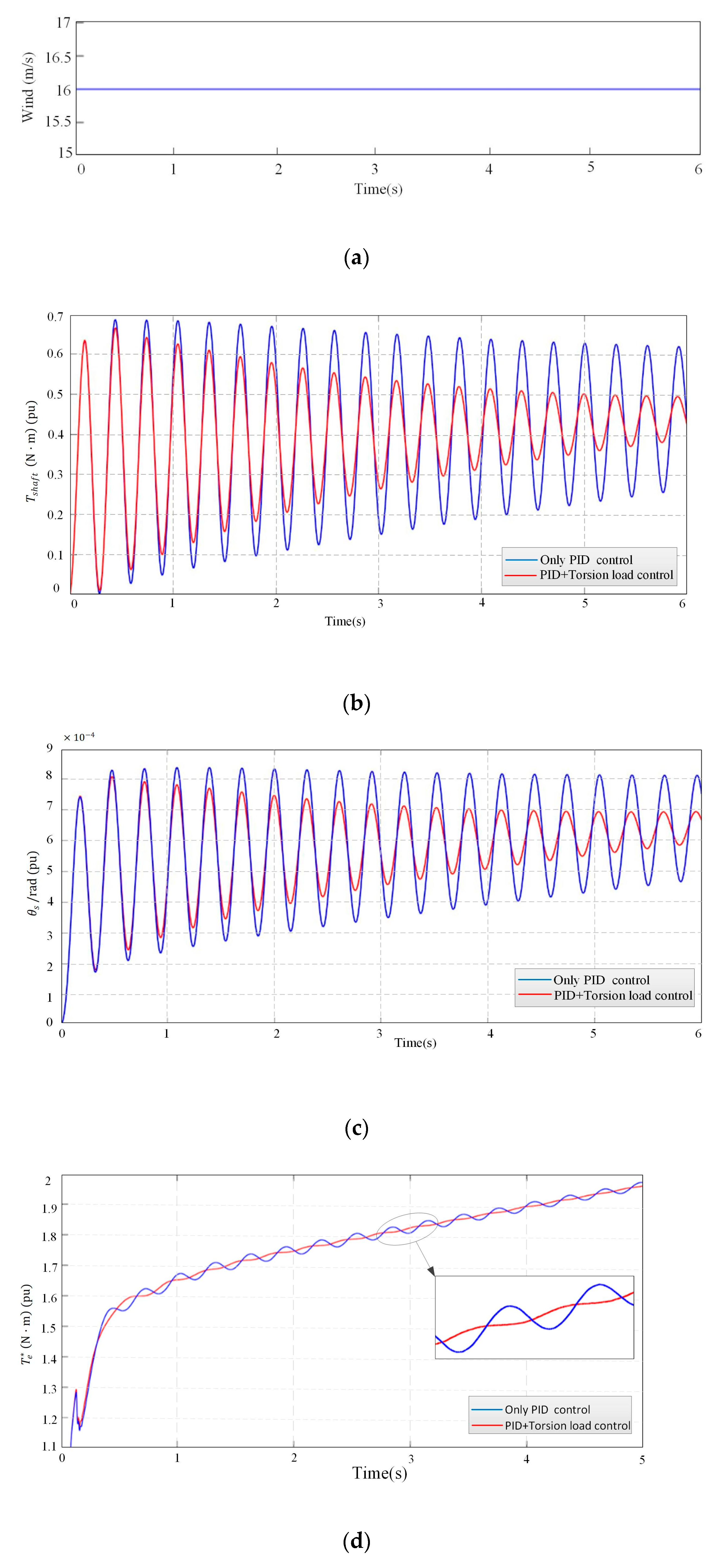
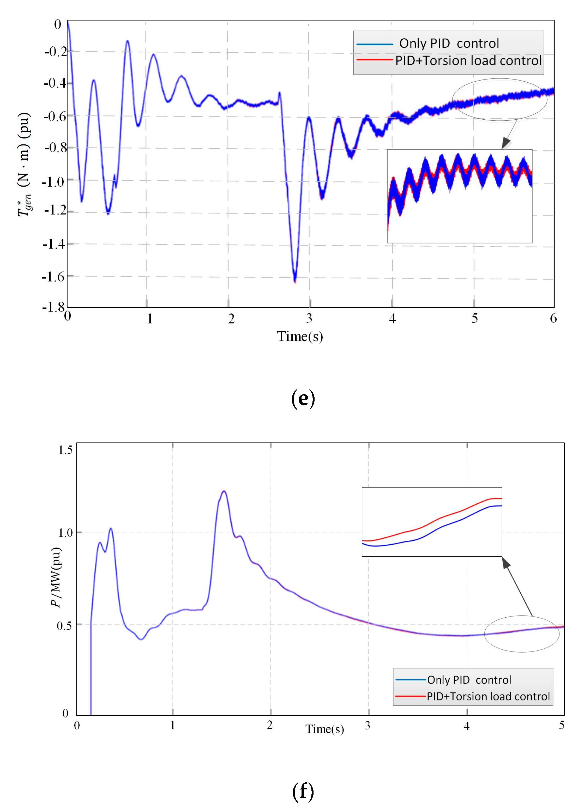
4.1. Simulation and Analysis under Constant Wind Speed (16 m/s)

Unless otherwise specified, all the simulations in this paper are carried out under the Per-unit value. At a constant wind speed (16 m/s), the simulation time is set to 6 s, the results are as follows in Figure 9.
Under constant wind speed (16 m/s), the simulation results Figure 9a–c show that the effect of suppressing the torsional vibration of the drive chain is not obvious only with the PID, the strategy of combined control of PID and torsional load proposed in this paper has a good effect on suppressing the torsional vibration of the drive chain. Simulation results Figure 9d–f show that the simulation curves of T g e n * and active power are basically coincident with only PID regulation, and PID regulation and torsional load control are combined; it shows that the control strategy proposed in this paper can effectively suppress the torsional vibration of the drive chain without affecting the power output.

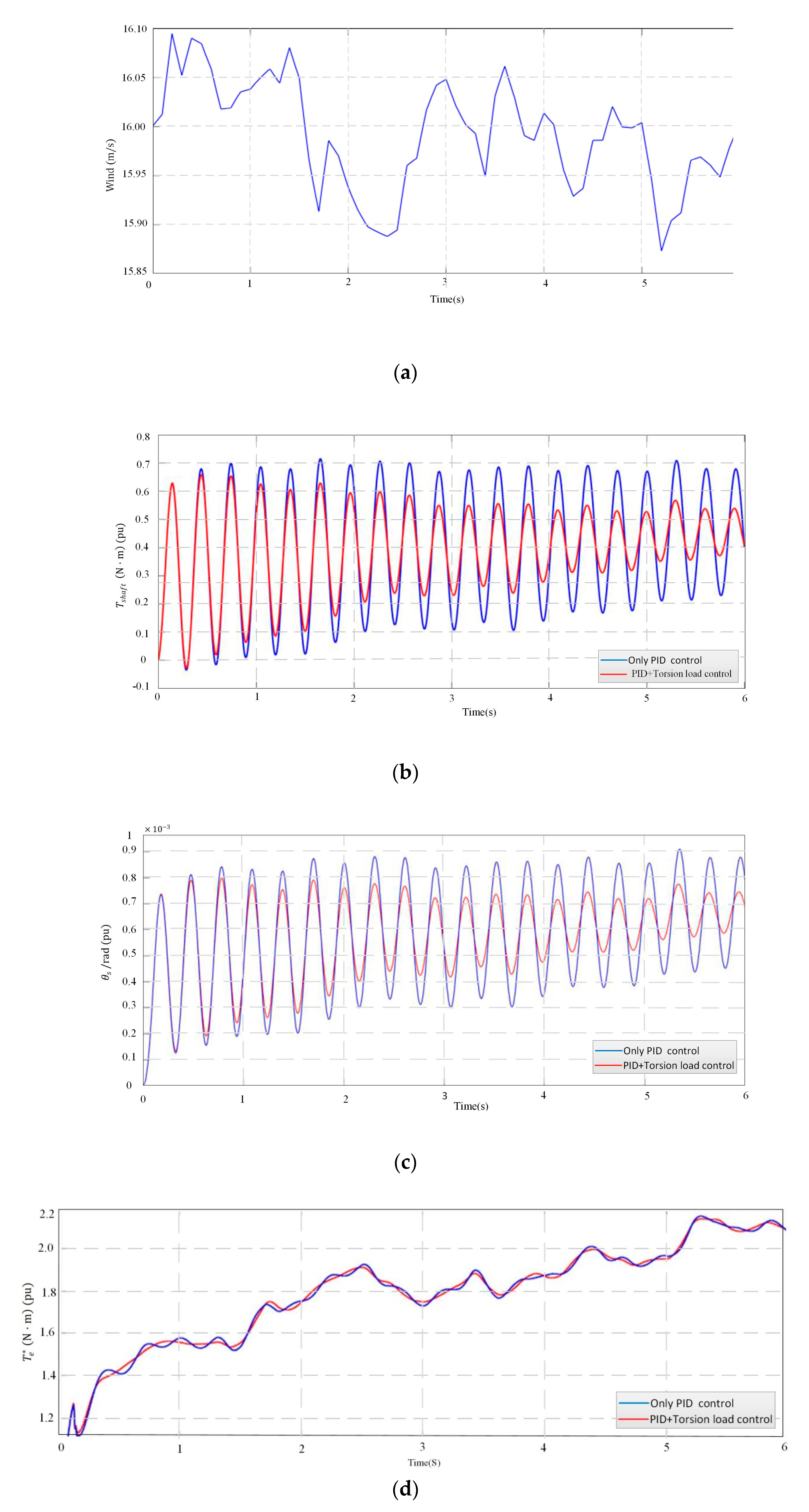
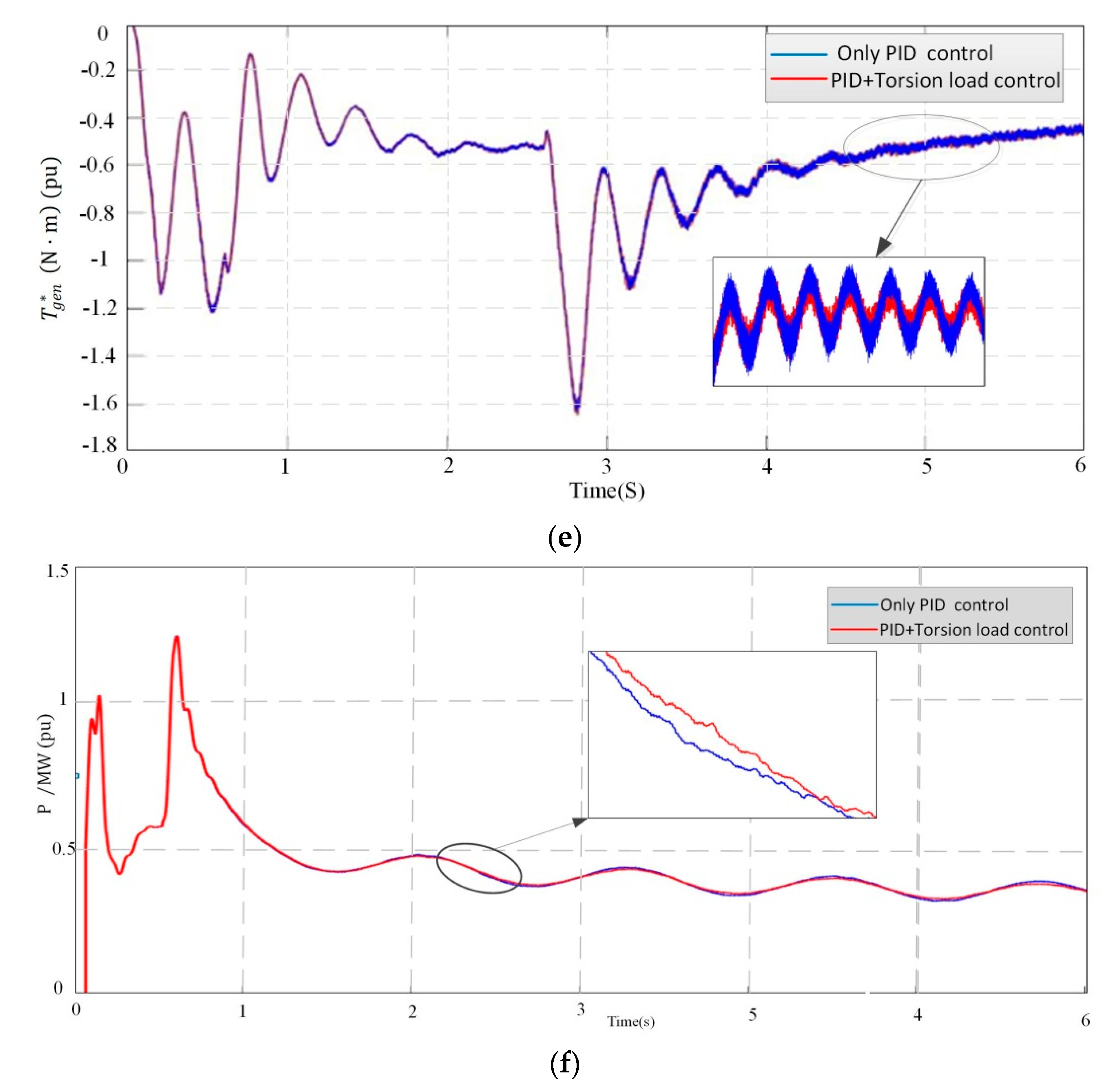
4.2. Simulation and Analysis under Turbulent Wind

In the turbulent wind condition, the same simulation time is set to 6 s, and the simulation results are shown in Figure 10.
Under turbulent wind conditions, it can be seen from Figure 10a–c that the torsional vibration of the drive chain is also effectively suppressed and has similar control effects with constant wind speed, indicating the control strategy proposed in this paper also has good control effect under complex wind conditions and has universal applicability. It can be seen from Figure 10d–f that the simulation curves of electromagnetic torque and active power are basically coincident with only PID regulation, and PID regulation and torsional load control are combined. It shows that the control strategy proposed in this paper can effectively suppress the torsional vibration of the drive chain without affecting the power output.

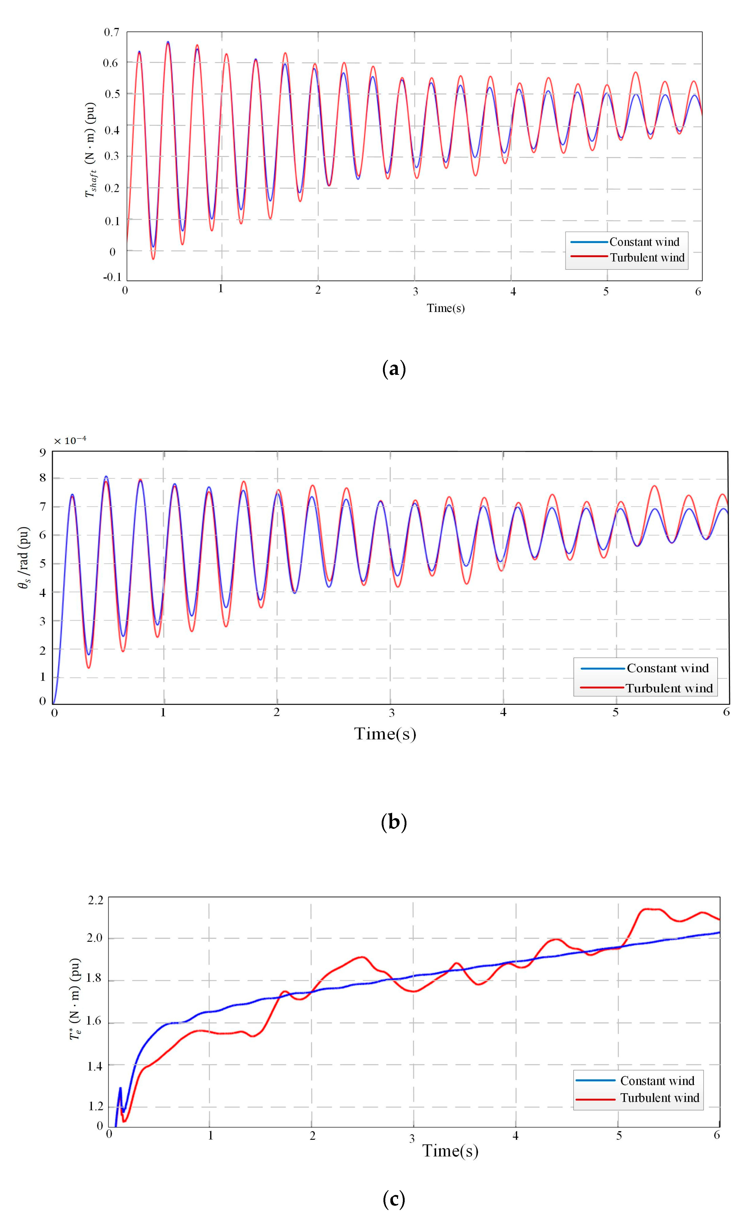
4.3. Under Constant Wind Speed (16 m/s) and Turbulent Wind

Under different wind speeds, in order to verify the control effect of the PID regulation and torsional load combined control strategy proposed in this paper, this section puts the simulation figure of constant wind speed (16 m/s) and turbulent wind in the same coordinate system, and simulation time is set to 6 s, as shown in Figure 11.
Figure 11a shows that the Tshaft of the drive chain will be different under different wind conditions, but under the PID regulation and torsional load combined control strategy, the turbulent wind condition Tshaft fluctuates near the constant wind condition. Figure 11b shows that the torsional vibration will be more serious in turbulent wind due to the uncertainty of the wind condition. However, under the PID regulation and torsional load combined control strategy, the turbulent wind condition θs fluctuates near the constant wind condition. Figure 11c shows that Te* will be different due to different wind conditions, through the control strategy, the turbulent wind condition Te* fluctuates near the constant wind condition. The constant wind condition only verifies the control performance of ideal conditions, and cannot be closer to reality, in order to be closer to the actual wind conditions under turbulence, the control strategy is verified. From the above results can be seen that the active control strategy proposed in this paper can effectively reduce the torsional vibration of drive chain under different wind conditions.

5. Conclusions

Aiming at a drive chain of a doubly fed WT with small damping and that is susceptible to torsional vibration load, a two-mass model of the drive chain is established. Through frequency domain analysis of the torsional vibration characteristics of the drive chain, it is found that the electromagnetic torque disturbance can cause more serious torsional vibration of the drive chain than the mechanical torque. In order to reduce torsional vibration of the drive chain during the normal operation of the power grid, a torsional load controller based on BPF and BRF is designed with the θs as feedback signal; combining PID and torsional load controller, a two-channel active damping control measure is proposed to suppress the torsional vibration of drive chain. The simulation results show that the control strategy proposed in this paper has better restraint effect on the torsional vibration of drive chain than with only PID, and the strategy has better adaptability when the input wind speed is uncertain, at the same time, it has no effect on the power output.

Author Contributions

M.L. designed the principles of the overall work and edited the final draft of paper; Z.L. realized MATLAB-based simulation and prepared the initial draft of paper; S.T. contributed significantly in writing the paper, Y.Z. and H.L. proposed some technical comments and edited the initial draft of paper.

Funding

This research was funded by Natural Science Foundation of China, grant number 51675354.

Conflicts of Interest

The authors declare no conflict of interest.

References

  1. Miao, F. Electromechanical Coupling Effect in DFIG-Wind Turbine Active Control for Load Reduction. Ph.D. Thesis, Beijing Jiaotong University, Beijing, China, 2017. (In Chinese). [Google Scholar]
  2. Ying, D.; Jie, G.; Tian, D.; Zhou, F.; Gao, S.; Zhao, M. Controlling structural vibrations in wind turbines by constructing function V. Sci. China Technol. Sci. 2015, 58, 1186–1195. [Google Scholar]
  3. Asgari, S.; Yazdizadeh, A. Robust model-based fault diagnosis of mechanical drive train in V47/660? kW wind turbine. Energy Syst. 2017, 9, 921–952. [Google Scholar] [CrossRef]
  4. Di, Z.; Ouyang, J.; Xiong, X.; Xiao, C.; Li, M. A System Transient Stability Enhancement Control Method Using Doubly Fed Induction Generator Wind Turbine with Considering Its Power Constraints. Energies 2018, 11, 945. [Google Scholar] [Green Version]
  5. Shen, Y.; Cui, M.; Wang, Q.; Shenm, F.; Zhang, B. Comprehensive Reactive Power Support of DFIG Adapted to Different Depth of Voltage Sags. Energies 2017, 10, 808. [Google Scholar] [CrossRef]
  6. Fateh, F.; White, W.N.; Grunbacher, D. Torsional Vibrations Mitigation in the Drivetrain of DFIG-based Grid-Connected Wind Turbine. IEEE Trans. Ind. Appl. 2017, 99, 1. [Google Scholar]
  7. Huang, P.H.; Moursi, M.S.E.; Hasen, S.A. Novel Fault Ride-Through Scheme and Control Strategy for Doubly Fed Induction Generator-Based Wind Turbine. IEEE Trans. Energy Conv. 2015, 30, 635–645. [Google Scholar] [CrossRef]
  8. Jia, F.; Wang, R.; Li, Z.; Cai, X.; Gao, Q. Torsional vibration suppression of DFIG drive-chain under grid fault. Electr. Power Autom. Equip. 2015, 35. [Google Scholar] [CrossRef]
  9. Zhao, J.; Lu, X.; Fu, Y.; Hu, X. Dynamic Frequency Control Strategy of Wind/Photovoltaic/Diesel Microgrid Based on DFIG Virtual Inertia Control and Pitch Angle Control. Proc. CSEE 2015, 35, 3815–3822. [Google Scholar]
  10. Rahimi, M. Improvement of energy conversion efficiency and damping of wind turbine response in grid connected DFIG based wind turbines. Int. J. Electr. Power Energy Syst. 2018, 95, 11–25. [Google Scholar] [CrossRef]
  11. Jun, L.; Feihang, Z.; Zhao, C.č.; Wang, Z. Mechanism analysis and suppression strategy research on permanent magnet synchronous generator wind turbine torsional vibration. ISA Trans. 2019, 10, 1016. [Google Scholar]
  12. Mohammadi, E.; Fadaeinedjad, R.; Moschopoulos, G. Implementation of internal model based control and individual pitch control to reduce fatigue loads and tower vibrations in wind turbines. J. Sound Vibr. 2018, 421, 132–152. [Google Scholar] [CrossRef]
  13. Liu, L.; Xie, D.; Chu, H.; Gu, C. A Damping Method for Torsional Vibrations in a DFIG Wind Turbine System Based on Small-Signal Analysis. Electr. Power Comp. Syst. 2017, 45, 560–573. [Google Scholar] [CrossRef]
  14. Ying, J.; Yuan, X.; Hu, J.; He, W. Impact of Inertia Control of DFIG-based WT on Electromechanical Oscillation Damping of SG. IEEE Trans. Power Syst. 2018, 33, 1. [Google Scholar] [CrossRef]
  15. Su, Y. Research on Active Suppression Strategy of Dynamic Load of Double-Fed Wind Turbine Drive Train. Master Thesis, Shenyang University of Technology, Shenyang, China, 2018. (In Chinese). [Google Scholar]
  16. Yilmaz, A.S.; Özer, Z. Pitch Angle Control in Wind Turbines Above the Rated Wind Speed by Multi-Layer Perceptron and Radial Basis Function Neural Networks. Expert Syst. Appl. 2009, 36, 9767–9775. [Google Scholar] [CrossRef]
  17. Akhmatov, V. Analysis of Dynamic Behaviour of Electric Power Systems with Large Amount of Wind Power. Ph.D. Thesis, Technical University of Denmark, Lyngby, Denmark, 2003. [Google Scholar]
  18. Muyeen, S.M.; Hasanali, M.; Rion, T.; Murata, T.; Tamura, J. Damping of Blade-shaft Torsional Oscillations of Wind Turbine Generator System. Electr. Mach. Power Syst. 2008, 36, 17. [Google Scholar] [CrossRef]
  19. Slootweg, J.G.; Polinder, H.; Kling, W.L. Representing Wind Turbine Electrical Generating Systems in Fundamental Frequency Simulations. IEEE Trans. Energy Conv. 2003, 18, 516–524. [Google Scholar] [CrossRef]
  20. Ping, D. Research on Active Control of Totsional Vibration in Wind Turbine Drive Train. Master Thesis, North China Electric Power University, Beijing, China, 2017. (In Chinese). [Google Scholar]
  21. Ponce, P.; Ponce, H.; Molina, A. Doubly fed induction generator (DFIG) wind turbine controlled by artificial organic networks. Soft Comput. 2018, 22, 2867–2879. [Google Scholar] [CrossRef]
  22. Kasmieh, T. Adaptive stator flux estimator for the induction machine Direct Torque Control. In Proceedings of the International Symposium on Power Electronics, Ischia, Italy, 11–13 June 2008. [Google Scholar]
  23. Andreas, P.; Lennart, H.; Torbjorn, T. Evaluation of current control methods for wind turbines using double-fed induction machines. IEEE Trans. Power Electr. 2005, 20, 227–235. [Google Scholar]
  24. Tapia, A.; Tapia, G.; Ostolaza, J.; Saenz, J. Modeling and control of a wind turbine driven doubly fed induction generator. IEEE Trans. Energy Conv. 2003, 18, 194–204. [Google Scholar] [CrossRef]
  25. Bedoud, K.; Ali-Rachedi, M.; Bahi, T.; Lakel, R.; Grid, A. Robust Control of Doubly Fed Induction Generator for Wind Turbine Under Sub-Synchronous Operation Mode. Energy Procedia 2015, 74, 886–899. [Google Scholar] [CrossRef]
  26. Luu, T.; Nasiri, A. Power Smoothing of Doubly Fed Induction Generator for Wind Turbine Using Ultra capacitors. In Proceedings of the IEEE Transactions IECON 2010 36th Annual Conference, Glendale, AZ, USA, 7–10 November 2010; pp. 3293–3298. [Google Scholar]
  27. Altun, H.; Sünter, S. Modeling, simulation and control of wind turbine driven doubly-fed induction generator with matrix converter on the rotor side. Electr. Eng. 2013, 95, 157–170. [Google Scholar] [CrossRef]
  28. Hu, J.; Hao, Y.; Yuan, X. Modeling of DFIG-Based WTs for Small-Signal Stability Analysis in DVC Timescale in Power Electronics Dominated Power Systems. IEEE Trans. Energy Conv. 2017, 99. [Google Scholar] [CrossRef]
  29. Derugo, P.; Szabat, K. Damping of torsional vibrations of two-mass system using adaptive low computational cost fuzzy PID controller. In Proceedings of the 11th International Conference on Power Electronics and Drive Systems, Sydney, Australia, 3–12 June 2015. [Google Scholar] [CrossRef]
  30. Yang, C. Active Control Strategies and Characteristics of Dynamic Loads of Wind Turbine Generator Systems. Ph.D. Thesis, Chongqing University, Chongqing, China, 2015. (In Chinese). [Google Scholar]
Figure 1. Diagram of Structure of Wind Turbine.
Energies 12 01744 g001
Figure 2. Cp curves suggested by Slootweg for dynamic analysis.
Energies 12 01744 g002
Figure 3. Drive chain model block diagram.
Energies 12 01744 g003
Figure 4. Schematic diagram of doubly-fed induction generator (DFIG) wind turbine system.
Energies 12 01744 g004
Figure 5. Orientation of the d-q frame.
Energies 12 01744 g005
Figure 6. Frequency domain characteristics of θ s ( s ) T e ( s ) and θ s ( s ) T t ( s ) .
Energies 12 01744 g006
Figure 7. Block Diagram of Drive Chain Damping Control.
Energies 12 01744 g007
Figure 8. Bode diagrams (a,b) are bandpass filter (BPF) and trap filter (BRF), respectively.
Energies 12 01744 g008
Figure 9. Simulation results under constant wind speed (16 m/s). (a) Wind speed (ωt) 16 m/s; (b) Output mechanical torque on the shaft (Tshaft); (c) Torsion vibration angle (θs); (d) Electromagnetic torque reference value (Te*); (e) The given value of the electromagnetic torque ( T g e n * ) ; (f) Active power (p).
Energies 12 01744 g009aEnergies 12 01744 g009b
Figure 10. Simulation Results under Turbulent wind. (a) Turbulent wind; (b) Output mechanical torque on the shaft (Tshaft); (c) Torsion vibration angle (θs); (d) The electromagnetic torque reference value (Te*); (e) The given value of the electromagnetic torque ( T g e n * ) ; (f) Active power (p).
Energies 12 01744 g010aEnergies 12 01744 g010b
Figure 11. Simulation Results under constant wind speed and turbulent wind. (a) Output mechanical torque on the shaft (Tshaft); (b) Torsion vibration angle (θs); (c) The electromagnetic torque reference value Te*.
Energies 12 01744 g011
Table 1. Optimized values of the Cp curve equations presented in [19].
C1C2C3C4C5C6C7C8C9
0.731510.580.0022.1413.218.4−0.02−0.003
Table 2. Wind turbine parameters of 1.5 MW doubly-fed.
CategoryValue
Type of Wind TurbinesDoubly-fed wind turbine
Rated power1.5 MW
Number of blades3.0
Rated speed18.0 r/min
Wind wheel diameter70.0 m
Power regulationVariable pitch angle and speed
Cutting into the wind 3.5 m/s
Cutting out the wind 25.0 m/s
Rated wind speed16.0 m/s
Table 3. Drive chain parameters of 1.5 MW double-fed WT.
CategoryValue
Wind wheel moment of inertia (Jt)4.45 × 10⁶ kg·m2
Generator moment of inertia (Jg)8.45 × 10⁵ kg·m2
Damping of drive chain (Ds)1.72 × 10⁵ N·m/rad
Stiffness of drive chain (Ks)3.03 × 10⁸ N·m/rad

