Article

Control Strategy for Power Conversion Systems in Plasma Generators with High Power Quality and Efficiency Considering Entire Load Conditions

1
Department of Electrical and Computer Engineering, Sungkyunkwan University, Suwon 16419, Korea
2
R&D Center, New Power Plasma, CO., LTD., Pyeongtaek 17703, Korea
*
Author to whom correspondence should be addressed.
Energies 2019, 12(9), 1723; https://doi.org/10.3390/en12091723
Submission received: 2 April 2019 / Revised: 26 April 2019 / Accepted: 2 May 2019 / Published: 7 May 2019
(This article belongs to the Special Issue Plasma Processes for Renewable Energy Technologies)

Abstract

:
In this paper, a control method for the power conversion system (PCS) of plasma generators connected with a plasma chamber has been presented. The PCS generates the plasma by applying a high magnitude and high frequency voltage to the injected gasses, in the chamber. With regards to the PCS, the injected gases in the chamber could be equivalent to the resistive impedance, and the equivalent impedance had a wide variable range, according to the gas pressure, amount of injected gases and the ignition state of gases in the chamber. In other words, the PCS for plasma generators should operate over a wide load range. Therefore, a control method of the PCS for plasma generators, has been proposed, to ensure stable and efficient operation in a wide load range. In addition, the validity of the proposed control method was verified by simulation and experimental results, based on an actual plasma chamber.

1. Introduction

There has been an increasing importance for a cleaning process in a semiconductor or a display manufacturing process, as manufacturing processes have become more precise and require a high yield rate [1,2]. The purpose of the cleaning process is to remove organic contaminants and particles on the surface of a semiconductor or a display. Cleaning processes are divided into wet cleaning process (using a chemical solution) and dry cleaning (a plasma cleaning) processes. Currently, the semiconductor cleaning process is moving away from the wet cleaning process to the dry cleaning process, because of environmental issues caused by chemical wastes and the development of precise semiconductor processes [2,3,4,5]. The dry cleaning process requires a plasma generator and it comprises a power conversion system (PCS), which supplies electric power to generate plasma, and a plasma chamber that serves as a load of the PCS. In this configuration, the PCS which generates a high-frequency and high-magnitude AC voltage, is an essential part to ensure a stable and efficient operation of the plasma generator.
When controlling the PCS for the plasma generator, the characteristics of the plasma chamber should be considered. According to the condition of the chamber such as the amount of injected gases, pressure, and plasma ignition states, the required input power of the chamber to be supplied by the PCS varies. In other words, when the chamber is equivalent to the load of the PCS, the load level of the PCS is changed, depending on the condition of the chamber. The equivalent impedance of the chamber is very large (ideally open), before the ignition of the injected gases and the impedance decreases, sharply after the ignition state. Therefore, the primary requirements of the PCS for a plasma generator is that it should have a constant characteristic, to prevent a short circuit problem after ignition. Additionally, the PCS should be capable of supplying high magnitude and high frequency voltage to the chamber in the initial state, to ignite the injected gases. The next requirement is that the PCS should supply high quality power to the chamber, regardless of the chamber conditions because high quality plasma gases can be generated when the input power quality of the chamber is high. This means that the output power quality of PCS determines the quality of the plasma gases. In addition, losses of the plasma generator occur in the PCS. Thus, the efficiency of the PCS is also important for an efficient operation of the plasma generator [5,6,7,8,9]. In previous studies on modular pulse generators, characteristics of plasma chambers, the system efficiency, and the output power quality were not seriously considered. Therefore, they were difficult to directly apply to plasma generators requiring a stable and efficient operation [10,11,12,13,14,15].
In the previous studies on PCS for plasma generators, the characteristics of the plasma chamber were considered. However, the PCS mainly consisted of a single-module PCS, and there were several disadvantages to this configuration [6,7,8,9]. The main disadvantage arose from a transformer with a high step-up ratio or a high magnitude of input voltage for the DC-AC inverter. In this case, the losses of inverters were increased because of the increasing input current or input voltage of the inverters. In addition, the design flexibility was decreased because the hardware design should have changed according to the rated power of the plasma generator. For these reasons, in this paper, input-parallel and output-series connected inverters were applied to the PCS for the plasma generator, as shown in Figure 1. As several inverters were connected, a flexible design was possible, according to the rated power. In addition, the input voltage of a filter network (vTR.S) was the sum of the secondary side voltages of the transformers, so a high output voltage could be generated, which was supplied to the chamber [16,17,18,19]. Another advantage was that, this configuration was not significantly affected by the unbalance between DC-AC inverters. When the secondary sides of the transformers were connected in parallel, problems of circulating currents could occur due to the unbalance between the connected DC-AC inverters. However, there was no circulating current in this configuration because the secondary sides were connected in series [18].
Several control methods have been proposed for the two-stage AC-AC converters in Figure 1. The first method employs an AC-DC converter that controls the DC-link voltage (VDC) at a constant value, and all of the connected inverters control the output power of the PCS, simultaneously [16,17]. When applying this control method, unnecessary power losses in the light and intermediate load region occur, because all of the connected inverters are used in the operation, even if one or two inverters are capable of controlling the output power. In addition, there is a disadvantage that the output power quality is decreased because THD of vtr.s, which is the input voltage of the filter network in Figure 1, is increased. The second method employs DC-AC inverters which operate with a fixed duty ratio, and the AC-DC converter controls the VDC at variable values, to control the output power [19]. When adopting this method, the quality of the output power does not degrade sharply. However, this method is not suitable for plasma generators because the impedance range of the plasma chamber is wide. Another control method employs DC-AC inverters, which control the shape of vTR.S as in the multi-level voltage waveforms [10,18]. However, these control methods mainly focus on the output power quality, and system efficiency is not seriously considered.
Therefore, in this paper, a control method of the two-stage AC-AC converter with input–parallel and output–series connected inverters, for plasma generators, is proposed. The proposed method controls the number of operating inverters by considering the output power level and the output power quality. Thus, by applying the proposed control method, not only the system efficiency but also the output power quality could be improved. Additionally, the validity of the proposed control method was verified through a simulation and an experiment based on an actual prototype of a PCS for plasma generators.

2. Conventional Control Algorithm of DC-AC Inverters for Plasma Generators

As shown in Figure 1, the two-stage AC-AC converter for the plasma generator consists of a three-phase AC-DC converter and DC-AC inverters. The three-phase AC-DC converter controls the input currents to ensure a high input power factor and controls the VDC. The DC-AC inverters are connected in input–parallel and output–series configuration, by transformers, and each inverter performs phase-shift control with a high switching frequency, such as 400 kHz. Among these PCSs, DC-AC inverters which are directly connected to the plasma chamber mainly affect the performance of the plasma generator. The requirements of the DC-AC inverter for plasma generator are as follows. (1) As inverters operate at a high switching frequency, a zero voltage switching (ZVS) operation is necessary. (2) After the ignition of injected gases, the equivalent impedance of the chamber decreases sharply. Therefore, the filter network can operate with a constant current output, to prevent overcurrent, even though the chamber impedance drops rapidly. (3) The DC-AC inverter should be able to supply high-quality output power to a plasma chamber, for high yield rates, by generating a high-quality plasma. To satisfy the first and second requirements, selection and design of the filter network is important. Among conventional filter networks, an LCL filter network satisfies these requirements [5,20,21]. To meet the third requirements, the control method of the DC-AC inverter is important, and the conventional control method has a limitation that the output power quality decreases in the light and intermediate load region. Figure 2 shows waveforms of the DC-AC inverters that are applied in the conventional control method. All of the connected inverters simultaneously transfer power from the primary side to the secondary side of the transformers. Therefore, there are several disadvantages of the conventional control method. (1) In the light and intermediate load region, the phase shift angle (α) is the phase angle of the operating inverter switches, S1 and S3 in Figure 1. As shown in Equation (1), THD of vTR.S is high when α is small. As a result, the power quality of the output power in the light load region decreases because vTR.S is the input voltage of the LCL filter network. (2) The efficiency of DC-AC inverters is drastically reduced because all of the connected inverters operate, even in the load region. In other words, unnecessary switching losses occur in the light and intermediate load region, when the conventional control method is applied.
T H D v = π α 8 sin 2 ( α 2 ) 1

3. Proposed Control Algorithm of DC-AC Inverters for Plasma Generators

3.1. Principle and Characteristics of the Proposed Control Algorithm

As shown in Equation (1) and Figure 3, when α of the inverters become less than 0.5π, THD of vTR.s is increased so the quality of the output power is decreased. To solve this problem, the proposed control method controls not only α but also the number of operating inverters (N). When N is reduced, α should be increased to output the same power. Therefore, the proposed control method has a wide operating range where THD of vTR.s is low in the light and intermediate load region, as shown in Figure 3. By employing this control method, the degradation of output power quality can be reduced, compared with that in the conventional control method. In addition, the efficiency of the PCS can be increased because N is reduced. The proposed control method is described in detail as follows. (1) As a high output voltage is required to ignite the injected gases, all connected inverters operate with a maximum value of N and α, at the initial start. (2) After ignition, the DC-AC inverter controls α according to the reference value. (3) When α becomes less than 0.5π, N is reduced. (4) After adjusting N, α is controlled according to the reference value. (5) Steps 2 to 4 are repeated until the output power of inverters and the reference value become the same or N becomes 1. (6) If N becomes 1, the operating inverter controls α without a lower limit of α. When the reference value is smaller than the output of inverters, N is increased when α becomes π. These steps are depicted as a flowchart in Figure 4. In this flowchart, VREF is the reference output voltage and Vsen is the sensing voltage of the output voltage of the PCS. Example waveforms for the proposed control method are shown in Figure 5. In order to prevent the injection of high-frequency induced currents to the DC-link, through the non-operating inverters, these inverters operate in a freewheeling mode (freewheeling inverters). The freewheeling current flows through the upper or lower switches. When the freewheeling current flows only through the upper or lower switches, thermal imbalance between the upper and lower switches in the same arm occurs. Therefore, as shown in Figure 6 that shows example gate signals of the operating and freewheeling inverters, the freewheeling path of freewheeling inverters is changed periodically. Additionally, the switching frequency of the freewheeling inverters should be relatively smaller than that of the operating inverters, to prevent high switching losses of freewheeling inverters.

3.2. Mathematical Model of the Proposed Control Algorithm.

In order to apply the proposed control method and to design the corresponding hardware, it is necessary to analyze the characteristics of the input–parallel and series–connected DC-AC inverters, based on the mathematical model. The fundamental voltage and the RMS voltage of vTR.S, in terms of N, α, and switching frequency (ωs) are shown in Equations (2) and (3).
v T R . S ( 1 ) ( t ) = 4 π N V D C sin ( α 2 ) sin ( ω s t )
V T R . S ( R M S ) ( 1 ) = 2 2 π N V D C sin ( α 2 )
The output voltage and the output current (io) can be derived from the input current (iINV) and the output gain, as shown in Equations (4) and (5). In this equation, Q is the Q factor of the LCL network, γ is the ratio of the inverter-side inductor (L1) to the load-side inductor (L2), and ωn is the ratio of the resonant frequency of the LCL network to the switching frequency [5,15,16].
H i n v = I i n v ( V T R . S ( R M S ) ( 1 ) L 1 / C f ) = ( 1 γ ω n 2 ) + j ω n Q 1 Q ( 1 ω n 2 ) + j [ ( 1 + γ ) ω n γ ω n 3 ]
H O = I O ( V T R . S ( R M S ) ( 1 ) L 1 / C f ) = 1 1 Q ( 1 ω n 2 ) + j [ ( 1 + γ ) ω n γ ω n 3 ]
Using Equations (4) and (5) the output current, output voltage, and inverter-side current can be derived as Equations (6)–(8), respectively, when the equivalent chamber impedance is Ro.
I O . r m s = 1 π Z n 2 2 ( 1 ω n 2 ) / Q + j [ ( 1 + γ ) ω n γ ω n 3 ] n V D C sin ( α 2 )
V O . r m s = 1 π Z n 2 2 ( 1 ω n 2 ) / Q + j [ ( 1 + γ ) ω n γ ω n 3 ] n V D C R O sin ( α 2 )
I i n v . r m s = 2 2 π Z n ( 1 γ ω n 2 ) + j ω n / Q ( 1 ω n 2 ) / Q + j [ ( 1 + γ ) ω n γ ω n 3 ] n V D C sin ( α 2 )
The DC-AC inverter and magnetic components are designed based on the mathematical analysis results, and the designed hardware is simulated and experimentally studied to verify the proposed control method.

4. Simulation and Experimental Results

The design of the plasma generator described in previous sections was applied to the simulation and an experiment. The specifications of the prototype, including the three-phase AC-DC converter and DC-AC inverters, connected in input–parallel and output–series configuration, are listed in Table 1. Using Equations (2) and (3), the RMS value of vTR.S (VTR.S(RMS)) was derived. To satisfy the output power condition at the calculated VTR.S(RMS), the required gain of the LCL filter network was 0.57 or higher. In addition, the resonant frequency of the LCL filter network for constant current operation should have been close to the switching frequency (400 kHz), so it was designed to be 450 kHz, at which the ZVS operation was possible. The parameters of the LCL filter network, which satisfied these conditions, could be derived using Equation (4), as shown in Table 2. Simulation and experiments were performed with the designed hardware, to verify the validity of the proposed control method.

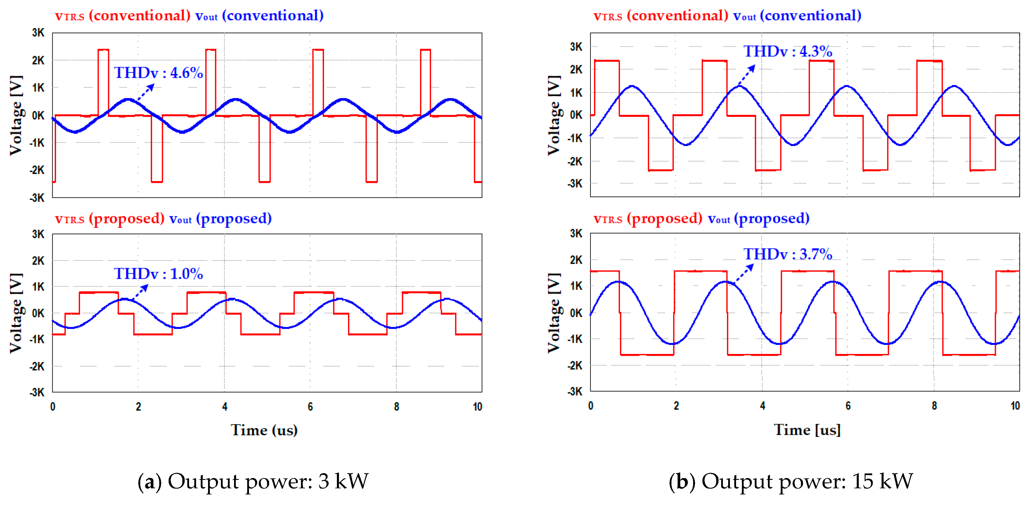
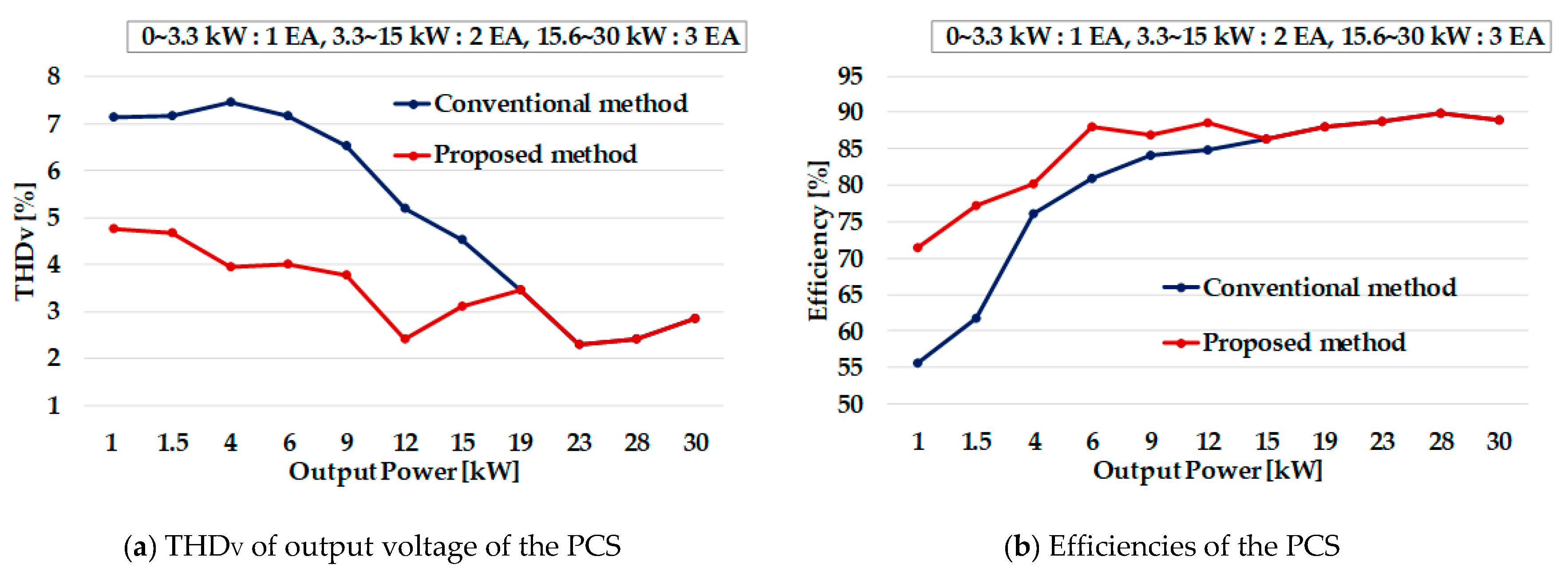
4.1. Simulation Results

The simulation was performed using PSIM based on the system parameters in Table 1 and Table 2. Three kW and 15 kW were set as the light load and intermediate load conditions, respectively. Figure 7 shows the simulation waveforms, when the proposed and conventional control methods were applied. As shown in these waveforms, α of vTR.S was relatively large when the proposed control method was applied, compared with α when the conventional control method was applied in the light and the intermediate load region. Therefore, the quality of the output voltage (vout) was higher for the proposed control method. From the simulation results, it could be confirmed that the proposed control method was more advantageous than the conventional control method, in the light and the intermediate load region.

4.2. Experimental Results

A prototype of the AC-DC converter and DC-AC inverters were designed using the same conditions as the simulation. The experimental environment is shown in Figure 8. Figure 9 shows the maximum output power, according to N and these experimental results corresponded to the simulation and the numerical analysis results. Figure 10 shows the results of a comparative experiment of the proposed and conventional control methods. When the output power exceeded 15.6 kW, the experimental waveforms of the proposed and conventional control methods were the same, because three inverters must operate in both control methods. However, when the output power was smaller than 15.6 kW, the experimental results showed that the maximum value of vTR.S was relatively small and α was relatively large, when applying the proposed control method. These experimental results showed that the proposed control method could improve the output power quality and increase the efficiency of the PCS, by reducing N. Finally, THDv of the output voltage and the system efficiency, according to the control methods, are presented in Figure 11. Figure 11a shows the THDv of the output voltage (i.e., the input voltage of the chamber). THDv was improved in the light load conditions when the proposed control method was applied (average 3% and maximum 3.5%). Likewise, the efficiency in the light load conditions was also improved because α of vTR.S was relatively large and N was small when applying the proposed control method in the light and intermediate load conditions. Therefore, the output power quality and the system efficiency were improved in the proposed control method. Both simulation and experimental results showed that the output power quality and system efficiency were improved in the light load condition, when the proposed control method was applied. Hence, these simulation results and experimental results validated the proposed control method.

5. Conclusions

In this paper, a control algorithm and design for plasma generators with input–parallel and output–series connected inverters were proposed by considering the characteristics of the plasma chamber. The proposed control method controlled the number of operating inverters, according to the chamber condition and controlled the inverter operation to make it suitable for a plasma generator with an input–parallel and output–series configuration. The proposed control method and the design method were verified through informative simulation and experiment. In addition, a comparative simulation and the experiment results of the proposed control method and conventional control method were presented. The simulation and experimental results showed that the proposed control method and design method could be successfully applied to a PCS for an actual plasma generator.

Author Contributions

Conceptualization, H.M.A.; Data curation, H.M.A. and E.J.; Formal analysis, H.M.A.; Investigation, H.M.A. and E.J.; Project administration, B.K.L.; Software, H.M.A. and E.J.; Supervision, B.K.L.; Validation, H.M.A. and C.S.L.; Visualization, H.M.A. and S.-H.R.; Writing–original draft, H.M.A. and B.K.L.; Writing–review & editing, H.M.A. and B.K.L.

Funding

This work was supported by “Human Resources Program in Energy Technology” of the Korea Institute of Energy Technology Evaluation and Planning (KETEP), granted financial resource from the Ministry of Trade, Industry & Energy, Republic of Korea. (No. 20184030202190)

Conflicts of Interest

The authors declare no conflicts of interest.

References

  1. Kamieniecki, E.; Foggiato, G. Analysis and control of electrically active contaminants by surface charge analysis. In Handbook of Semiconductor Wafer Cleaning Technology, 3rd ed.; Noyes Publications: Park Ridge, NJ, USA, 1993; pp. 497–536. ISBN 978-032-351-084-4. [Google Scholar]
  2. Chen, X.; Holber, W.; Loomis, P.; Sevillano, E.; Shao, S.Q. Advances in Remote Plasma Sources for Cleaning 300 mm and Flat Panel CVD Systems. Semiconductor® Magazine, 20 August 2003. [Google Scholar]
  3. Jin, Y.; Ren, C.S.; Fan, Q.Q.; Yan, H.; Li, Z.; Zhang, J.; Wang, D. Surface Cleaning Using an Atomospheric-Pressure Plasma Jet in O2/Ar Mixtures. IEEE Trans. Plasma Sci. 2003, 40, 2706–2710. [Google Scholar] [CrossRef]
  4. Balish, K.E.; Nowak, T.; Tanaka, T.; Beals, M. Dilute Remote Plasma Clean. U.S. Patent 6329297B1, 11 December 2001. [Google Scholar]
  5. Yong-Nong, C.; Chih-Ming, K. Design of Plasma Generator Driven by High-frequency High-Voltage Power Supply. J. Appl. Res. Technol. 2013, 11, 225–234. [Google Scholar] [CrossRef]
  6. Tran, K.; Millner, A. A New Power Supply to Ignite and Sustain Plasma in a Reactive Gas Generator. In Proceedings of the 2008 Twenty-Third Annual IEEE Applied Power Electronics Conference and Exposition (2008 APEC), Austin, TX, USA, 24–28 February 2008; pp. 1885–1892. [Google Scholar]
  7. Kim, Y.M.; Kim, J.Y.; Mun, S.P.; Lee, H.W.; Kwon, S.K.; Suh, K.Y. The design of inverter power system for plasma generator. In Proceedings of the 2005 International Conference on Electrical Machines and Systems, Nanjing, China, 27–29 September 2005; pp. 1309–1312. [Google Scholar]
  8. Ahn, H.M.; Sung, W.Y.; Lee, B.K. Analysis and Design of Resonant Inverter for Reactive Gas Generator Considering Characteristics of Plasma Load. J. Electr. Eng. Technol. 2018, 13, 345–351. [Google Scholar] [CrossRef]
  9. Chen, W.; Zhuang, K.; Ruan, X. A Input-Series- and Output-Parallel-Connected Inverter System for High-Input-Voltage Applications. IEEE Trans. Power Electron. 2009, 24, 2127–2137. [Google Scholar] [CrossRef]
  10. Abdelsalam, I.; Elgenedy, M.A.; Ahmed, S.; Williams, B.W. Full-bridge Modular Multilevel Submodule-based High-voltage Bipolar Pulse Generator with Low-voltage DC, Input for Pulsed Electric Field Applications. IEEE Trans. Plasma Sci. 2017, 45, 2857–2864. [Google Scholar] [CrossRef]
  11. Luc-André, G.; Bélanger, J. A Modular Multilevel Converter Pulse Generation and Capacitor Voltage Balance Method Optimized for FPGA Implementation. IEEE. Trans. Ind. Electron. 2015, 62, 2859–2867. [Google Scholar] [CrossRef]
  12. Elgenedy, A.M.; Darwish, A.; Ahmed, S.; Williams, B.W. A Modular Multilevel-Based High-Voltage Pulse Generator for Water Disinfection Applications. IEEE Trans. Plasma Sci. 2016, 44, 2893–2900. [Google Scholar] [CrossRef]
  13. Elserougi, A.A.; Massoud, A.M.; Ahmed, S. A Modular High-Voltage Pulse-Generator with Sequential Charging for Water Treatment Applications. IEEE. Trans. Ind. Electron. 2016, 63, 7898–7907. [Google Scholar] [CrossRef]
  14. Mohamed, A.; Darwish, A.; Williams, B.W. A Transition Arm Modular Multilevel Universal Pulse-Waveform Generator for Electroporation Applications. IEEE. Trans. Power. Electron. 2017, 32, 8979–8981. [Google Scholar] [CrossRef]
  15. Rocha, L.L.; Silva, J.F.; Redondo, L.M. Multilevel High-Voltage Pulse Generation Based on a New Modular Solid-State Switch. IEEE Trans. Plasma Sci. 2014, 42, 2956–2961. [Google Scholar] [CrossRef]
  16. Fang, T.; Ruan, X.; Tse, C.K. Control Strategy to Achieve Input and Output Voltage Sharing for Input-Series-Output-Series-Connected Inverter Systems. IEEE Trans. Power Electron. 2010, 25, 1585–1596. [Google Scholar] [CrossRef]
  17. Guo, Z.; Sha, D.; Liao, X.; Luo, J. Input-Series-Output-Parallel Phase-Shift Full-Bridge Derived DC–DC Converters with Auxiliary LC Networks to Achieve Wide Zero-Voltage Switching Range. IEEE Trans. Power Electron. 2014, 29, 5081–5086. [Google Scholar] [CrossRef]
  18. Ahn, H.M.; Sung, W.Y.; Kim, M.K.; Ryu, S.H.; Lim, C.S.; Lee, B.K. Control Method of Input-Parallel and Output-Series Connected Inverters for Plasma Generator. In Proceedings of the 2018 IEEE Applied Power Electronics Conference and Exposition (APEC), San Antonio, TX, USA, 4–8 March 2018; pp. 3563–3568. [Google Scholar]
  19. Alou, P.; Oliver, J.; Cobos, J.A.; Garcia, O.; Uceda, J. Buck+half Bridge (d=50%) Topology Applied to very Low Voltage Power Converters. In Proceedings of the 2001 Sixteenth Annual IEEE Applied Power Electronics Conference and Exposition (2001 APEC), Anaheim, CA, USA, 4–8 March 2001; pp. 715–721. [Google Scholar]
  20. Borage, M.; Tiwari, S.; Kotaiah, S. Analysis and Design of an LCL-T Resonant Converter as a Constant-Current Power Supply. IEEE Trans. Ind. Electron. 2005, 52, 1547–1554. [Google Scholar] [CrossRef] [Green Version]
  21. Bhat, A.K.S. A Fixed Frequency LCL-Type Series Resonant Converter. IEEE Trans. Aerosp. Electron. Syst. 1995, 31, 97–103. [Google Scholar] [CrossRef]
Figure 1. Configuration of the two-stage AC-AC converter for plasma generators.
Energies 12 01723 g001
Figure 2. Example waveforms of DC-AC inverters with the conventional control method.
Energies 12 01723 g002
Figure 3. Comparison of operating areas according to the control methods.
Energies 12 01723 g003
Figure 4. Flow chart of the proposed control method.
Energies 12 01723 g004
Figure 5. Example waveforms of DC-AC inverters with the proposed control method.
Energies 12 01723 g005
Figure 6. Gate signals of an operating inverter and a freewheeling inverter.
Energies 12 01723 g006
Figure 7. Waveforms of DC-AC inverter according to the output power and control methods.
Energies 12 01723 g007
Figure 8. Experimental environment.
Energies 12 01723 g008
Figure 9. Waveforms in the maximum output condition according to the number of operating inverters.
Energies 12 01723 g009
Figure 10. Waveforms of inverters according to control methods.
Energies 12 01723 g010
Figure 11. Experimental results of the PCS for the plasma generator.
Energies 12 01723 g011
Table 1. Specifications of the power conversion system (PCS) for plasma generators.
AC-DC Converter
ParameterValue
Rated Power30 kW
Grid voltage3Φ 440VLL.RMS
Grid frequency60 Hz
Switching frequency10 kHz
DC-link voltage800 Vdc
DC-AC Inverter
ParameterValue
Rated Power10 kW (1 EA)
Number of connected inverters3 EA
Switching frequency (operating inverter)400 kHz
Switching frequency (freewheeling inverter)10 kHz
Turn ratio of transformer1
Equivalent resistor of chamber (Ro)50 Ω
Table 2. Specifications of the designed LCL filter network for the PCS.
ParameterValue
L126 uH
L220 uH
Cf4.7 nF

