1. Introduction
Climate and environmental crisis problems that have emerged in recent years, have led to the proposition of new energy solutions, including the substitution of combustion engines by electrical systems accompanied with Li-ion batteries. The CO
2 intensity of electric vehicles (EVs) can be determined by the specific mixture of power generation sources used for driving, such as coal, nuclear, or renewable power sources, as well as the carbon intensity of the vehicle manufacturing process. The high energy efficiency components of electric vehicles allow them to significantly cut CO
2 emissions with respect to internal combustion engines. The IEA (International Energy Agency) (2017a) observed that, in 2015, electric cars in Europe emitted ~50% less CO
2 than gasoline cars and 40% less than diesel cars [
1].
To increase the driving range of EVs, a large number of high energy density Lithium-ion batteries should be installed. However, Lithium-ion batteries have a shortcoming in heat resistance—a temperature that is too high or too low will result in a drastic reduction in battery capacity and service life [
2,
3]. Studies have shown that the heat inside Lithium-ion batteries is mainly induced from reactions that produce Ohmic heat and polarization heat [
4,
5,
6]. Various models have been proposed based on these heat generation mechanisms. Among them, the most widely used model is the Bernardi model because of its simple logics and reasonable accuracy [
7]. Heubner et al. [
8] conducted research on the heat generation of a LiCO
2/graphite lithium ion battery with a 0.2–1 C discharge rate (discharge rate 1 C = battery capacity/one hour). Total heat generation was between 50 and 150 kJ/L. Liu [
9] carried out the research on cell aging due to heat generation under conditions of 2 and 4 C. The maximum heat generation was 9 and 35 W, respectively. Todd M. Bandhauer [
10] investigated the heat generation of C/LiFePO
4 lithium ion batteries with different current magnitudes. He reported that heat generation reached 200 W/L with a current of 5 A. Heat generation from a LiFePO
4 (20 Ah) battery was investigated by Panchal [
11], who showed that the rate of heat generation was 13 W for a discharge rate of 1 C.
Conventional air cooling and water cooling methods have been used to solve the thermal problem of batteries. Choi [
12] investigated the effect of the wind speed on air cooling using a battery size of 240 mm × 130 mm × 13.4 mm, a channel size of 210 mm × 2–6 mm, and a coolant flow rate of 2–6 m
3/h. Under a wind speed of 6 m
3/h and a 40 A square pulse cycle, the temperature of the battery cell was maintained at about 37.5 °C. Yu [
13] conducted air convection cooling for a battery pack with a size of 620 mm × 430 mm × 310 mm and a coolant flow rate of 0.1–2 m
3/min. Under a 1 C discharge rate and an air flow rate of 2 m
3/min, the maximum temperature of the new battery pack was reduced by nearly 4.5 °C compared to the original pack. Ling [
14] performed research work on air cooling methods for 18,650 battery cooling. The spacing between centers of two neighboring cells was 30 mm and the wind speed was varied between 1 and 5 m/s. Under a discharge rate of 1.5 C and an air speed of 1 m/s, the battery’s maximum temperature rose sharply to 60 °C, and under air speeds higher than 3 m/s, the temperature was kept below 45 °C. Bai [
15] reported a PCM (phase change material) battery cooling method with a water flowing cold plate. The battery size used was 170 mm × 230 mm × 12 mm, the height of the cold plate was 2–7 mm, and the mass flow rate was 0.25–3 g/s. After five continuous charge–discharge cycles at 0.5 and 2 C, the maximum temperature was kept below 42 °C. However, due to the small flow passage, a 42 Pa pressure drop was observed at a channel width of 3 mm. Tong [
16] investigated various parameters of a cooling system with a water coolant plate, such as the flow rate, section size, and discharge rate. Under a coolant velocity of 0.1 m/s and a discharge rate of 1 C, the average temperature difference was only 2 °C. Huo [
17] investigated a mini channel cold plate cooling system with six 1 mm thick micro channels. At a flow rate of 1 kg/s, the maximum temperature was maintained between 30 and 32 °C. However, the pressure loss reached 478 Pa. To make the data compatible for EV/HEV (hybrid electric vehicle) application, Panchal [
18] developed a modified exponential–polynomial equivalent circuit model to simulate the temperature and voltage fields with water cooling. Under a discharge rate of 1–2 C and working temperatures of 5, 15, 25, and 35 °C, the model showed good agreement with the experimental results.
However, due to the low thermal conductivity of air and the large volume of the air cooling system, the cooling system requires a large heat transfer surface area and flow passage for air convection cooling. Furthermore, due to the high viscosity of water, the water cooling system requires extra energy to circulate liquid.
The importance of the heat pipe as a thermal superconductor for thermal management is gradually being realized. Liu [
19] carried out research on battery cooling with an ultra-thin micro heat pipe (168 mm × 10 mm × 1 mm). In their system, one end of the heat pipe is inserted between the batteries, and the other end is a finned sink. When air cooling was conducted at a discharge rate of 3 C, the maximum temperature of the battery was 53 °C. Wang [
20] investigated the battery cooling method with an L-shaped heat pipe. The heat pipe evaporation section was flattened (120 mm × 13.16 mm × 4.5 mm), and the lower condensation section was cylindrical (length = 50 mm and diameter = 10 mm). Under a heating rate of 20 W/cell, the maximum temperature of the battery was about 50 °C. Hong [
21] investigated the loop heat pipe battery cooling system with system inclination and battery heat generation. The evaporation section of a loop heat pipe is a flat plate with 25 micro-channels (width = 3 mm and depth = 0.6 mm) inside it. The inner and outer diameters of the loop pipe were 2.4 and 3 mm, respectively.
Due to the importance of thermal management in high heat generation Li-ion batteries, heat pipes are adopted in many cooling system as an efficient heat transfer device, but most heat pipe-adapted cooling systems are bottom heating-top or side cooling systems. These types of cooling system have good cooling performance but take up a lot of space. In addition, their structures are not convenient in terms of battery maintenance.
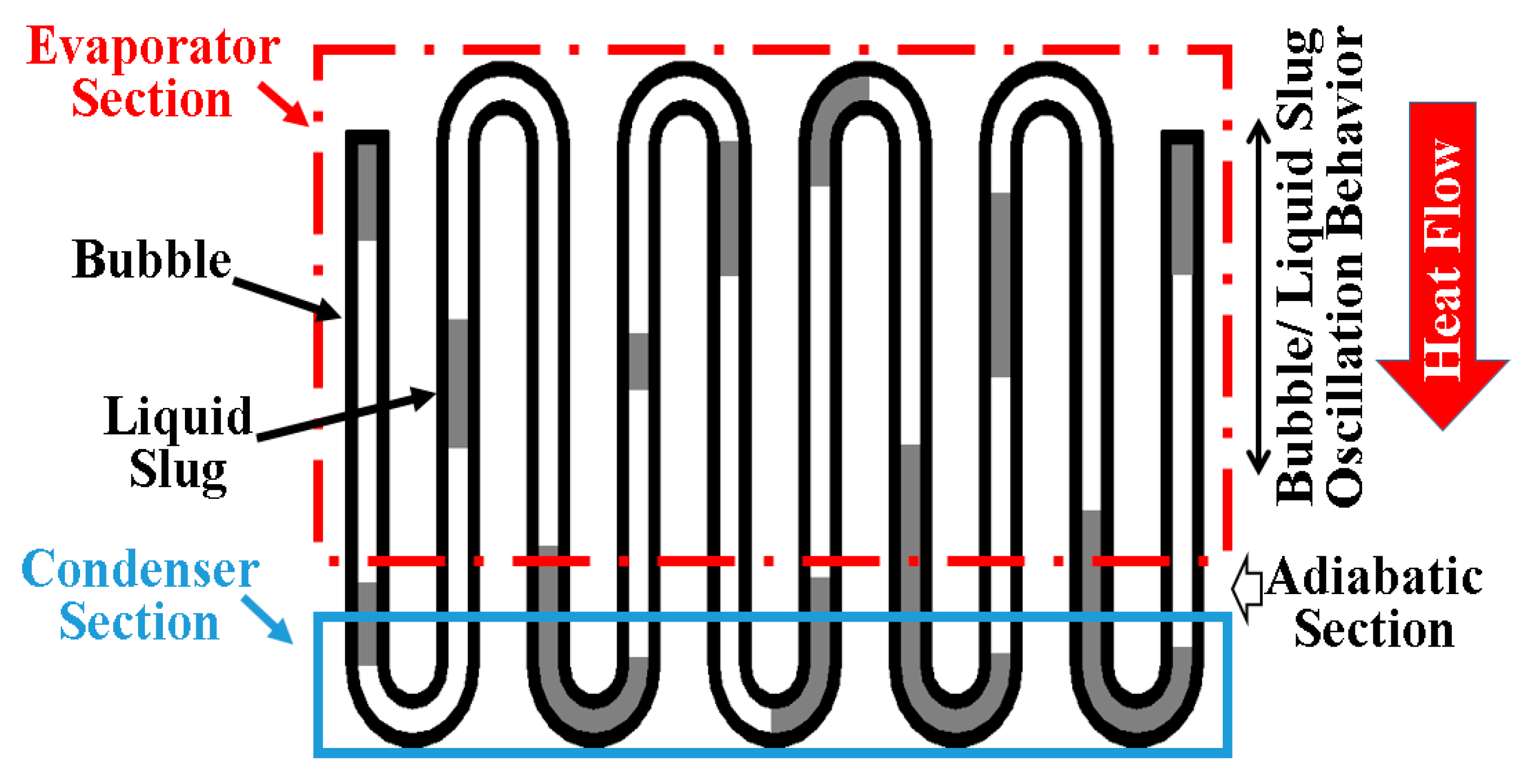
OHP, a highly efficient and simple-structured type of heat pipe, is now being studied extensively. As shown in
Figure 1, it consists of a curved channel and working fluid, which can be described as the evaporator, adiabatic, and condenser sections. Because the vapor bubble is separated by multiple liquid slugs, when the heat is supplied to the evaporator section, a pressure difference is created between the bubbles, causing the liquid plug to oscillate between the evaporator section and the condenser section, thereby transferring heat.
Rao [
22] studied the OHP (four turns, inner diameter = 1.8 mm, and outer diameter = 3 mm) for battery cooling. Under 20 W of heating, at 800 s, steady state was reached, and the maximum temperature was about 55 °C. In another paper, Rao reported on a cooling system that combined OHP and PCM (phase change material) [
23]. Although its cooling performance was shown to be good, it is still bottom heating/top cooling. Qu [
24] used a special OHP for the battery thermal management of hybrid-electric vehicles. The condensation section and evaporation section of OHP were a micro-grooved copper tube system. At 121 W, the micro-grooved cooling system could maintain a temperature of 50 °C.
Chi [
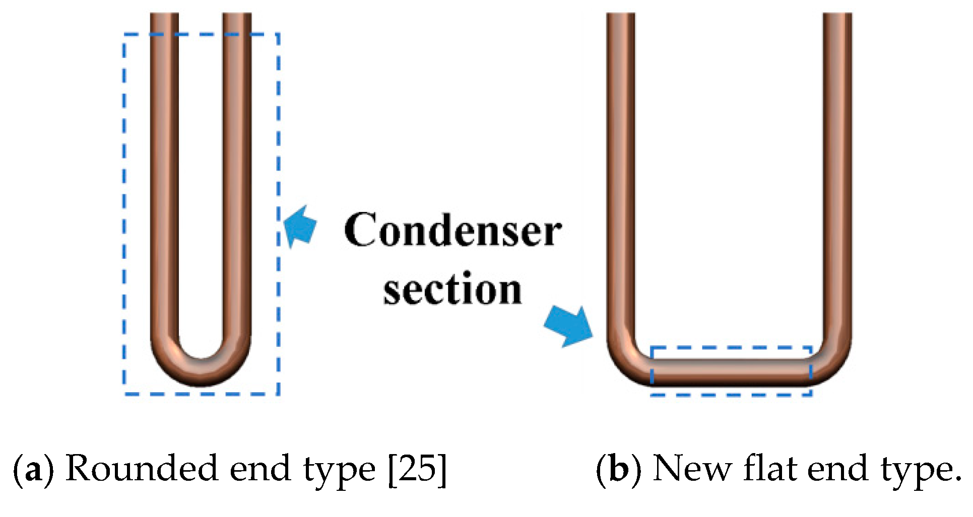
25] proposed a top heating/bottom cooling OHP model shown in
Figure 1. As shown in
Figure 2a, their OHP cooling system has the conventional rounded lower end with a short (15 mm) condenser section. However, as the number of OHP increases, the structure of cooling of system will also become more complicated.
According to the cooling method used to transfer heat from the battery to the outside environment, cooling technology can carry out various liquid cooling methods (air, water, oil-based fluids, and refrigerants, etc.) and PCM. In addition, heat pipe cooling technology is also under development [
7,
26].
Table 1 shows the comparison of various cooling methods. As described in
Table 1, liquid cooling methods are mainly divided into direct and indirect method. The direct cooling type involves direct immersion of the battery into the high-resistance coolant, so the cooling efficiency is very high. However, there are several problems, such as electrical short-circuiting, electrochemical corrosion, and sealing. Furthermore, the battery is immersed in the coolant, so maintenance and replacement will be very troublesome. Indirect type involves letting water flow through the channel between the batteries. Compared with the direct type, some problems are alleviated, but since the channels are generally small and the pressure drop is also very large, the pump consumes a lot of electric energy, thereby reducing the electric vehicle travel [
7,
27,
28]. Due to the low specific heat and low thermal conductivity, the efficiency of air cooling is very low. However, the structure is simple and there is no disadvantage of water cooling, so the method of increasing the flow rate or the cross-section of the passage is used in the battery cooling of the electric vehicle [
7,
27,
28]. PCM cooling uses the principle of heat absorption during phase change. Although PCM can absorb a large amount of heat, its thermal conductivity is low, for example, paraffin has a thermal conductivity of only 0.149–0.514
. The temperature will increase dramatically after PCM melts; therefore, PCM is used in combination with air cooling or liquid cooling. Moreover, the PCM density is large, and if used in a large amount, the battery space is reduced [
26,
27,
29,
30].
As a heat superconductor, the heat pipe is capable of rapid heat transfer. In most studies, the cooling section is in the upper part of the battery. This structure affects battery maintenance and updates. As a special heat pipe, OHP can work without gravity. Moreover, it is small in size and diverse in shape, so it can be applied to a large number of diverse batteries. The OHP proposed in this paper has a heating section that is much larger than the cooling section (~20 times), so the cooling effect is not ideal. However, with the adjustment of parameters, we believe that the performance of OHP will get better and better.
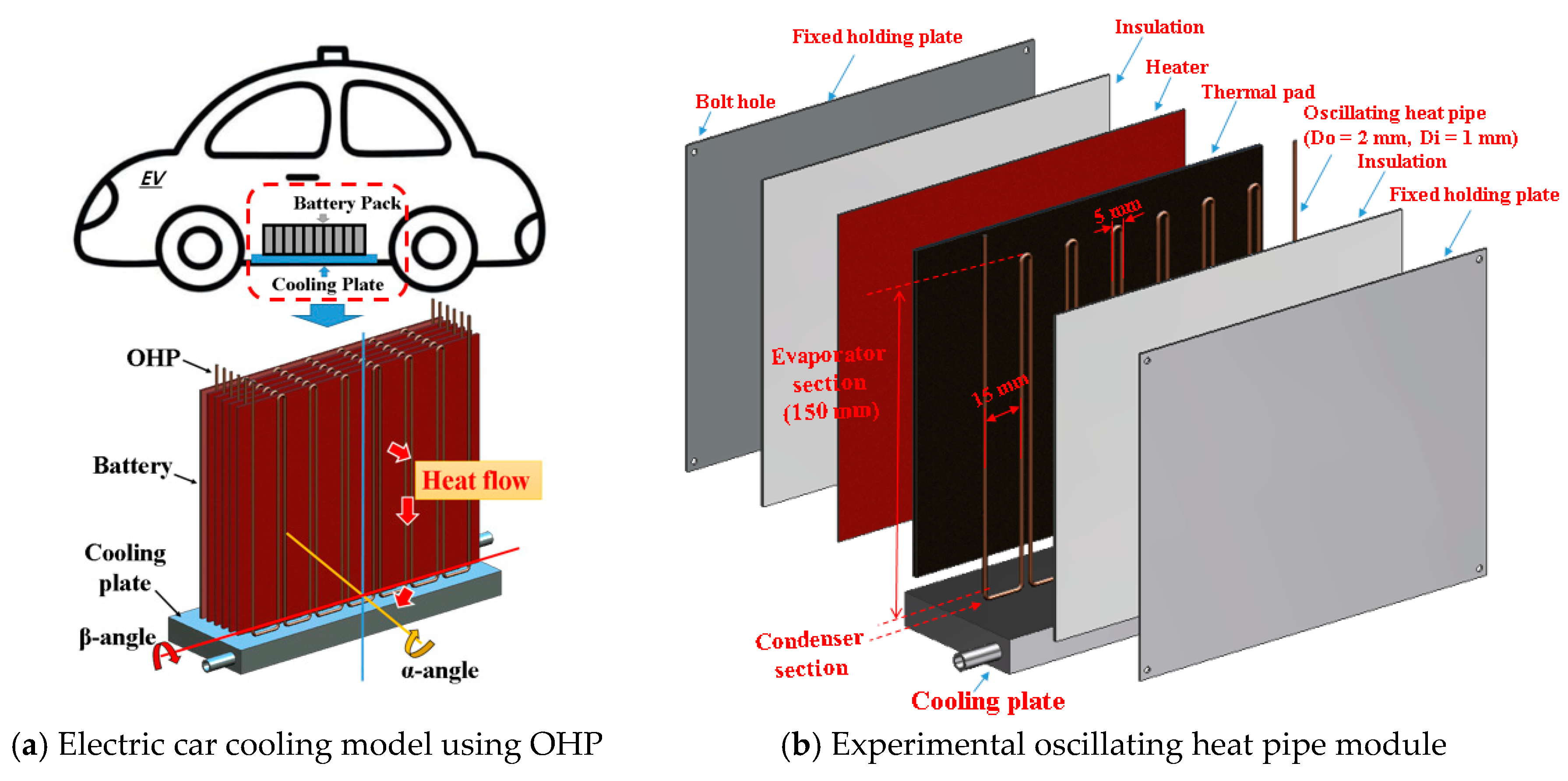
The present study investigated an OHP (Oscillating Heat Pipe) battery cooling system with a condenser directly contacting the cold plate surface in bottom cooling mode, as shown in
Figure 2. The performance and various effects of the system’s operating parameters, such as the charging rate, orientation, pipe size, and supplied heating rate, were assessed.
2. Experiments
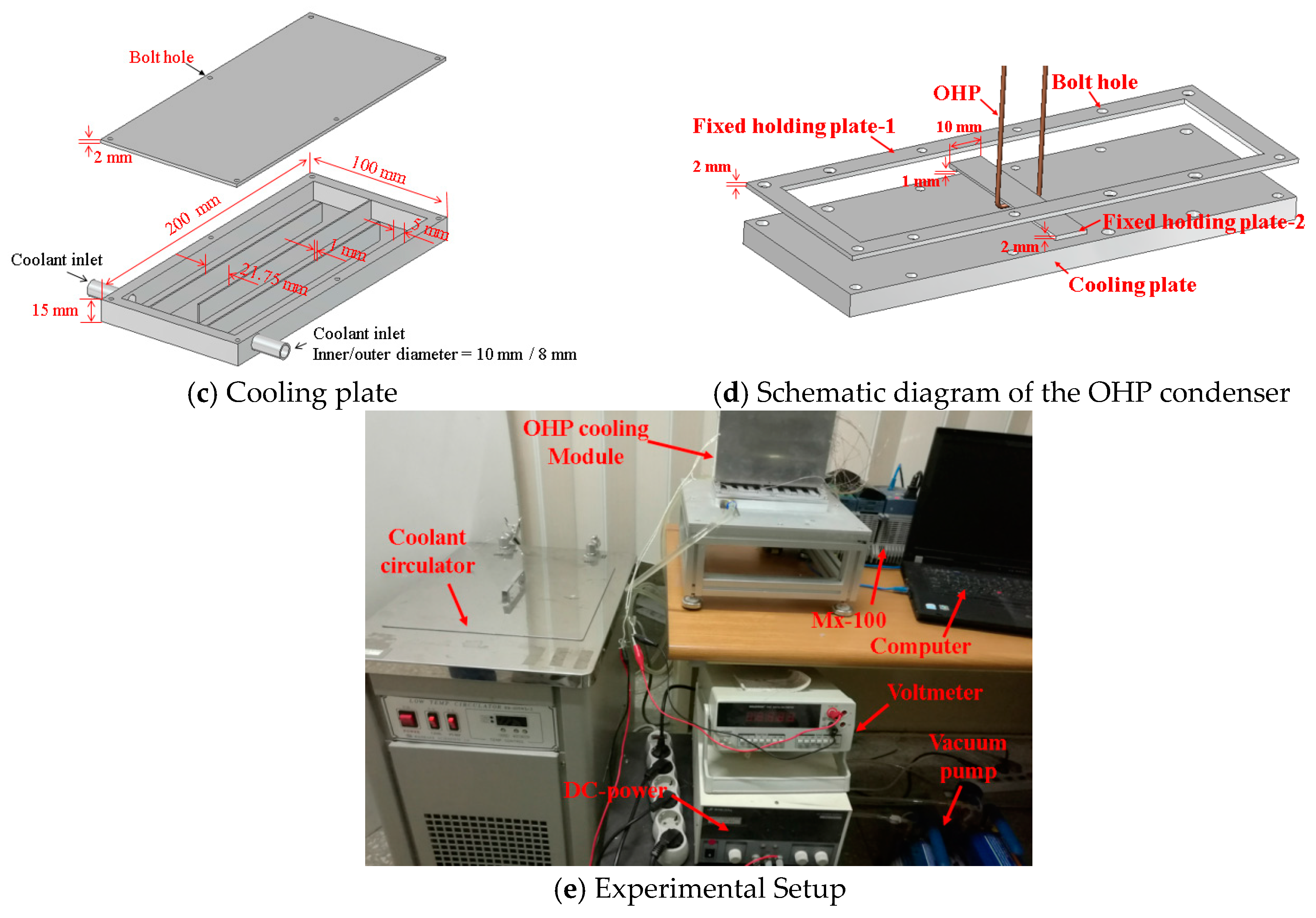
Figure 3a–e shows a battery cooling system with the new type of OHP, which will be applied to an electric vehicle.
Figure 3b,e shows the present experimental setup accompanied by the OHP. The experimental setup mainly consists of an OHP, a heater, a DC-power supply (DP30-10DU, TOYOTECH, Incheon, Korea), a water flowing cooling plate (0.01 kg/s), and a multichannel data acquisition system (Yokogawa, MX-100). The maximum critical inner diameter of the OHP can be obtained by Equations (1) and (2). Furthermore, the cooling plate has two passing flow channels, as shown in
Figure 3c, and is made of aluminum alloy and sealed with a silicone ring. The bottom end outer surface of the condenser section in the OHP directly contacts the top surface of the cooling plate system. In order to reduce the thermal resistance between the cooling plate and the condenser section of the OHP, the condenser end and the cooling plate were bolt jointed tightly between fixed holding plate-1 and fixed holding plate-2, as shown in
Figure 3d.
Despite the simple structure of the OHP, the physical flow behavior inside it is very complex, and its performance is affected by many different parameters, including the thermo physical properties of the working fluid. The OHP channel diameter for randomly separating the pulsating liquid slug/vapor plug flow of the OHP must have a Bond number ≤ 4, as determined by Equation (1) [
31]. If the Bond number is greater than 4, the surface tension will not withstand the buoyancy driven force, and the vapor plug will not be able to collapse, so it will maintain a stable shape.
In light of this,
Dcr can be defined as Equation (2):
Using Equation (2), when the working fluid is methanol, the critical inner diameter
Dcr of OHP is ~3.2 mm. Based on this critical inner diameter of OHP, a few commercial copper tube combinations were tested. The test OHPs were fabricated using copper capillary tubes (D
o/D
i = 1.8 mm/0.8 mm, D
o/D
i = 2 mm/1 mm, D
o/D
i = 2.4 mm/1.4 mm), and the end side of the evaporator was bent to 180
o with a 5 mm curvature diameter. The bottom side of the condenser was a straight pipe of 10 mm length, bent at 90
o with a 5 mm curvature diameter. The OHP had eight turns, as shown in
Figure 3b. The resistance flat heater (190 mm × 150 mm) was used to simulate the Li-ion battery, which is modeled as an LG chem Li-ion car battery. Heat generation rates of 10, 14, and 20 Watts were used based on information from the literature [
7,
11].
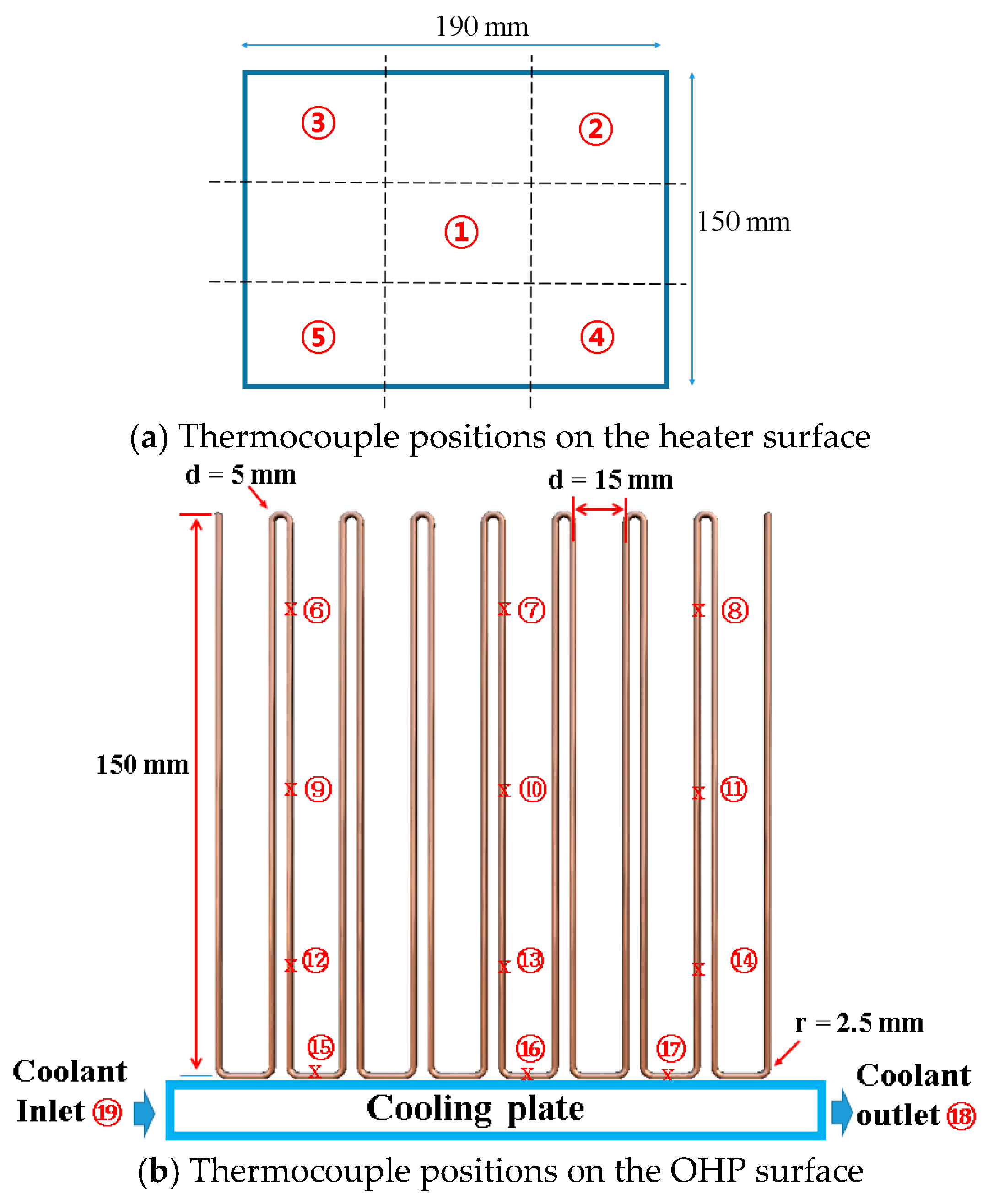
In the present experimental system, K-type thermocouples (TT-K-36-SLE, Omega, Stamford, CT, USA) and a data acquisition module (MX-100, Yokogawa, Tokyo, Japan) were used to measure temperatures in many positions. The temperature measurement points of the thermocouples are shown in
Figure 4 in the following positions: numbers 1–5 in the heater surface, numbers 6–8 in the upper part of the evaporation section of the OHP, numbers 9–11 in the middle part of the evaporation section of the OHP, numbers 12–14 in the bottom part of the evaporation section of the OHP, numbers 15–17 in the condenser section of the OHP, and numbers 18 and 19 in the coolant outlet and inlet.
To estimate the thermal performance of the OHP and the system, the thermal resistances of the OHP and the system were estimated by Equations (3)–(5). The OHP operation based on the charging rate was evaluated with R
OHP, where
,
, and
are the average temperatures of the nine evaporator positions, three condenser positions, and five heater positions, respectively, and
is the coolant inlet point. Input heat was supplied to the evaporator using a DC power transformer through a flat thermal pad. The input power was calculated by Equation (6), where
V and
I are the input voltage and electric current, respectively [
32].
In the present work, the parameters influencing the thermal resistance were the temperature (T), current (I), and voltage (V). The voltage and current error of the DC power supply was ± (0.1% rdg + 5 digits), and the temperature error of MX-100 was ± (0.05% rdg + 0.7 °C).
and
are the sensitivity coefficient and the error of each parameter, respectively, and they were calculated by Equation (7) [
33]:
Finally, the standard uncertainty error of
, which was calculated by Equation (8), under heating at 10 W was ± 0.12 °C/W.
To analyze the oscillation behavior of the temperature at a specific location on the OHP, the Fast Fourier Transform (FFT) method was applied for temperature position no. 16, which is an interface temperature position between the evaporator and the condenser. The FFT Power Spectrum Density (PSD) was calculated by Equation (9), where
is the auto-correlation function of the input signal. The PSD and frequency were computed by Equations (10) and (11), where
and
are the number of input data points and the sampling interval, respectively [
34]:
3. Results and Discussion
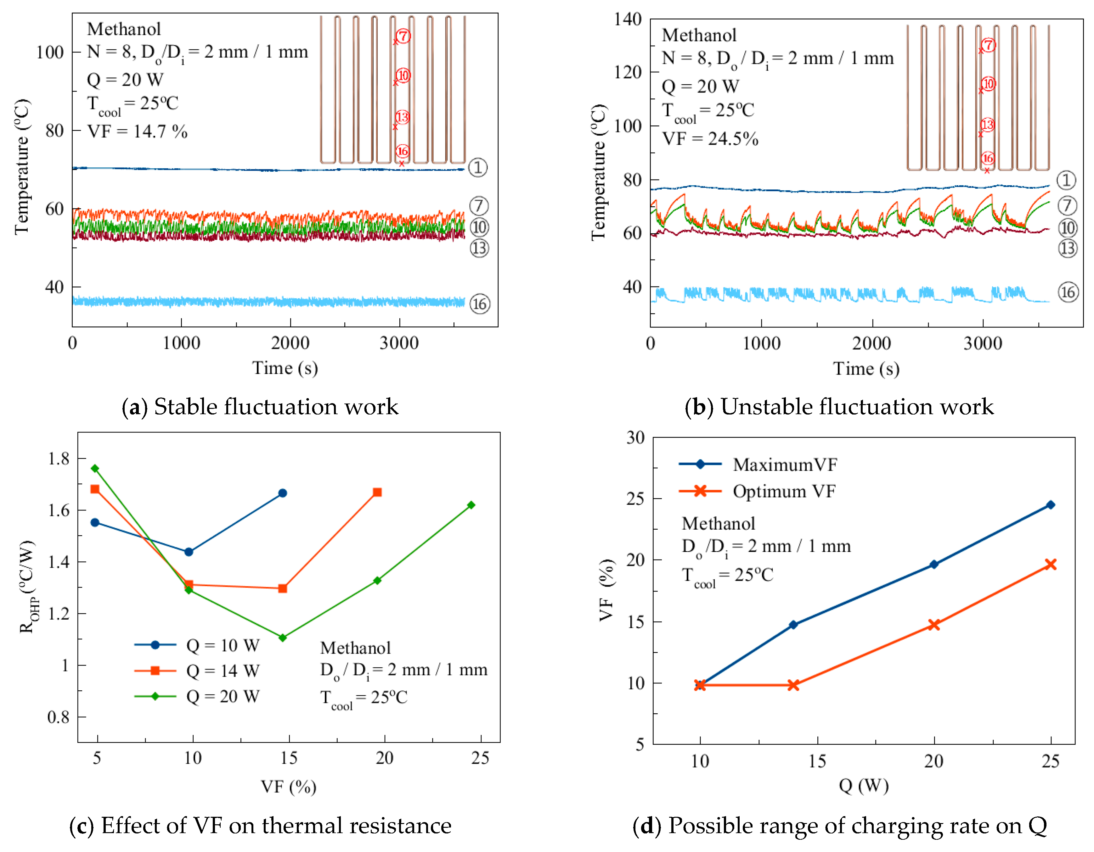
Figure 5a,b shows two types of OHP working conditions with different amounts of charge. Under constant heating (Q = 20 W) and a certain range of charge (volume fraction (VF) = 14.7%), the OHP system temperature shows stable oscillatory behavior. However, if this range is exceeded, the working status will change from stable to intermittently unstable behavior. As shown in
Figure 5a, the temperature oscillation of the evaporation section is constantly maintained in the range of 50–60 °C. However, when VF increased to 24.5% with the same heat flux, the temperature of the evaporation section largely fluctuated from 60 to 70 °C. When the Q was 10 W and the VF increased from 4.9% to 9.8%, the thermal resistance of OHP decreased from 1.5 to 1.43 K/W. However, when the VF increased to 14.7%, the thermal resistance of OHP increased to 1.66 K/W due to intermittent temperature fluctuations. When Q was 14 W, the minimum value of the thermal resistance (1.29 K/W) was observed at a VF of 14.7%. When Q increased to 20 W, the optimal value of VF was still 14.7% and the thermal resistance of OHP was 1.11 K/W. Generally, as VF increased, the thermal resistance of OHP decreased firstly, and then increased with increasing VF, as shown in
Figure 5c. This is because if the charged amount of working fluid is insufficient, the working fluid cannot be sufficiently supplied to the evaporator section of OHP, resulting in a dry-out and increased OHP thermal resistance. If Q also increases, the dry-out phenomena in the evaporator becomes more serious and the thermal resistance of OHP increases, as shown in the
Figure 5c with VF = 4.9%. With the increase of VF, dry-out is well activated in the evaporation section of OHP and thermal resistance of OHP also reduces. However, when the amount of working fluid is not excessive, the pressure drop will increase between the liquid and pipe wall, the motion of working fluid will be resisted, intermittent fluctuated operation occurs, and then subsequently, the thermal resistance will increase. When VF is sufficiently large with an increasing Q, the temperature difference will also increase between the evaporator and condensation sections. This will lead to an increased pressure difference between working fluids in both sections. Heat transfer is stable and thermal resistance is reduced at a VF of 9.8–14.7%, as shown in
Figure 5c. This means that the optimum charging rate of an OHP system should be correctly determined.
Figure 5d shows a certain optimum and maximum criteria range for the charging rate, which is observed as a working condition.
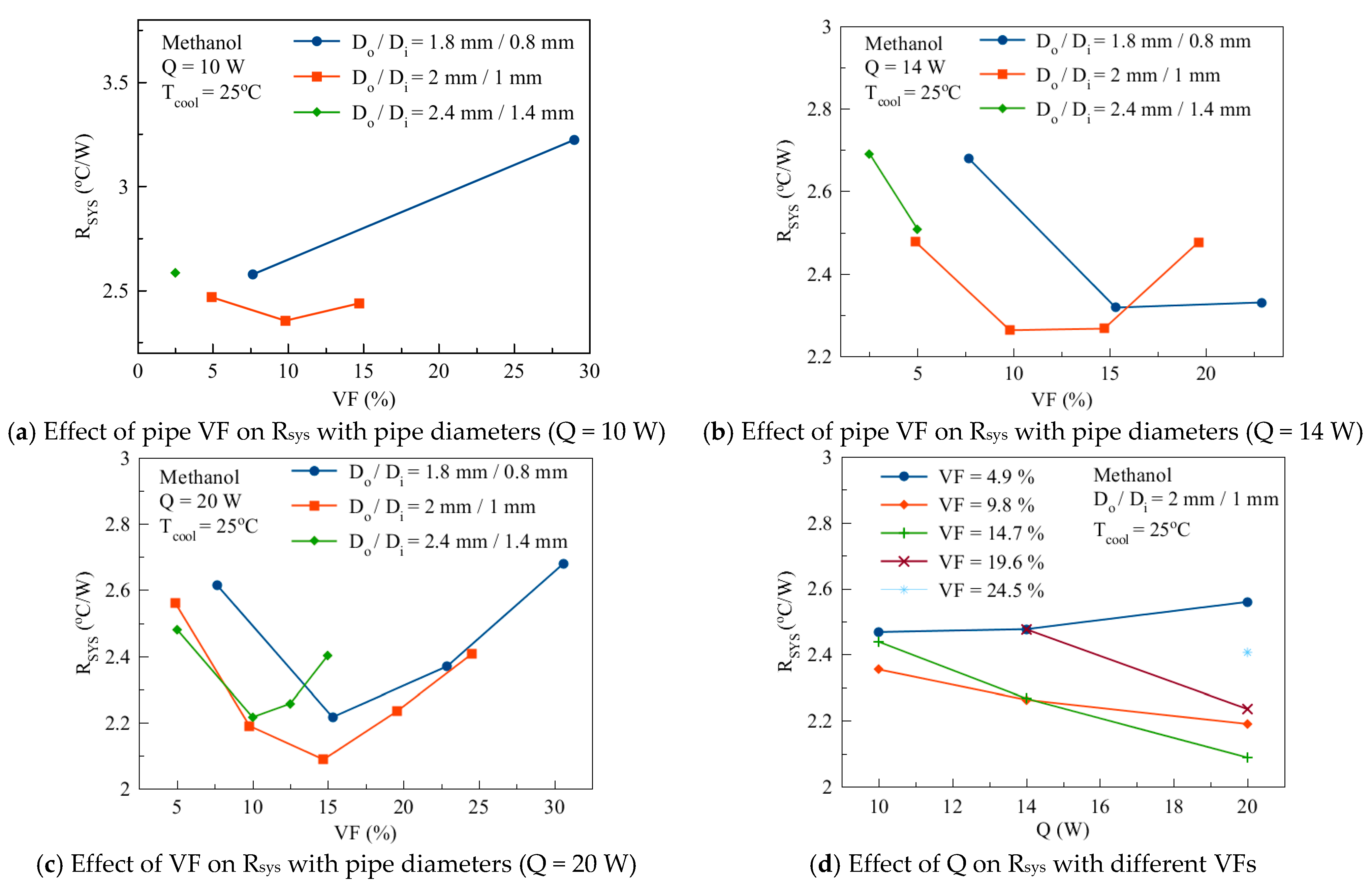
The contact thermal resistance between the tube and the heater or cooling plate is affected by the diameter of the tube.
Figure 6 shows the thermal resistance of the cooling system between the heater surface and the cooling plate under a constant heating rate in the OHP with different tube diameters and with different amounts of charge. When the D
o/D
i was 1.8 mm/0.8 mm, the optimal VF was about 15%. When the D
o/D
i was 2 mm/1 mm, the optimal VF was 10–15%. However, when the D
o/D
i was 2.4 mm/1.4 mm, the optimal VF was about 2–10%. From this, we know that the smaller the pipe diameter is, the bigger the optimal VF and the maximum VF are. This is because the larger the diameter, the larger the volume of OHP; pressure changes in the working fluid are also slow. However, in contrast, the smaller the diameter, the larger the pressure drop.
Figure 6d also shows the effect of Q on thermal resistance with different VFs. The figure shows that the best working performance in terms of the thermal resistance was obtained when VF was 9.8%. When VF was 9.8%, the plot line trend of thermal resistance with Q was not steeper than a VF of 14.7%. This means that the optimum charging rate is a VF of 9.8%.
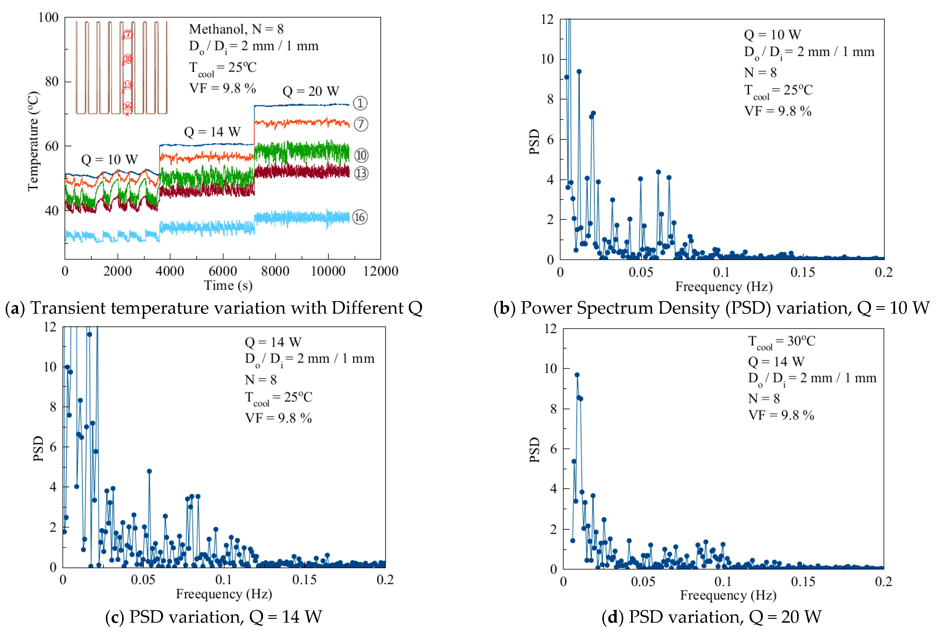
Figure 7 shows the PSD of temperature position no. 13 with a D
o/D
i of 2 mm/1 mm and a VF of 9.8% with different heat fluxes. As shown in
Figure 7a–d, when Q was 10 W, a larger PSD was distributed in the low frequency region (0–0.75 Hz). In the high frequency region, the PSD was small with a value of less than 1. When Q increased to 14 W between 0.075 and 0.125 Hz, PSD obviously increased. Compared with Q values of 10 and 14 W, PSD obviously increased across the full frequency range when Q was 20 W.
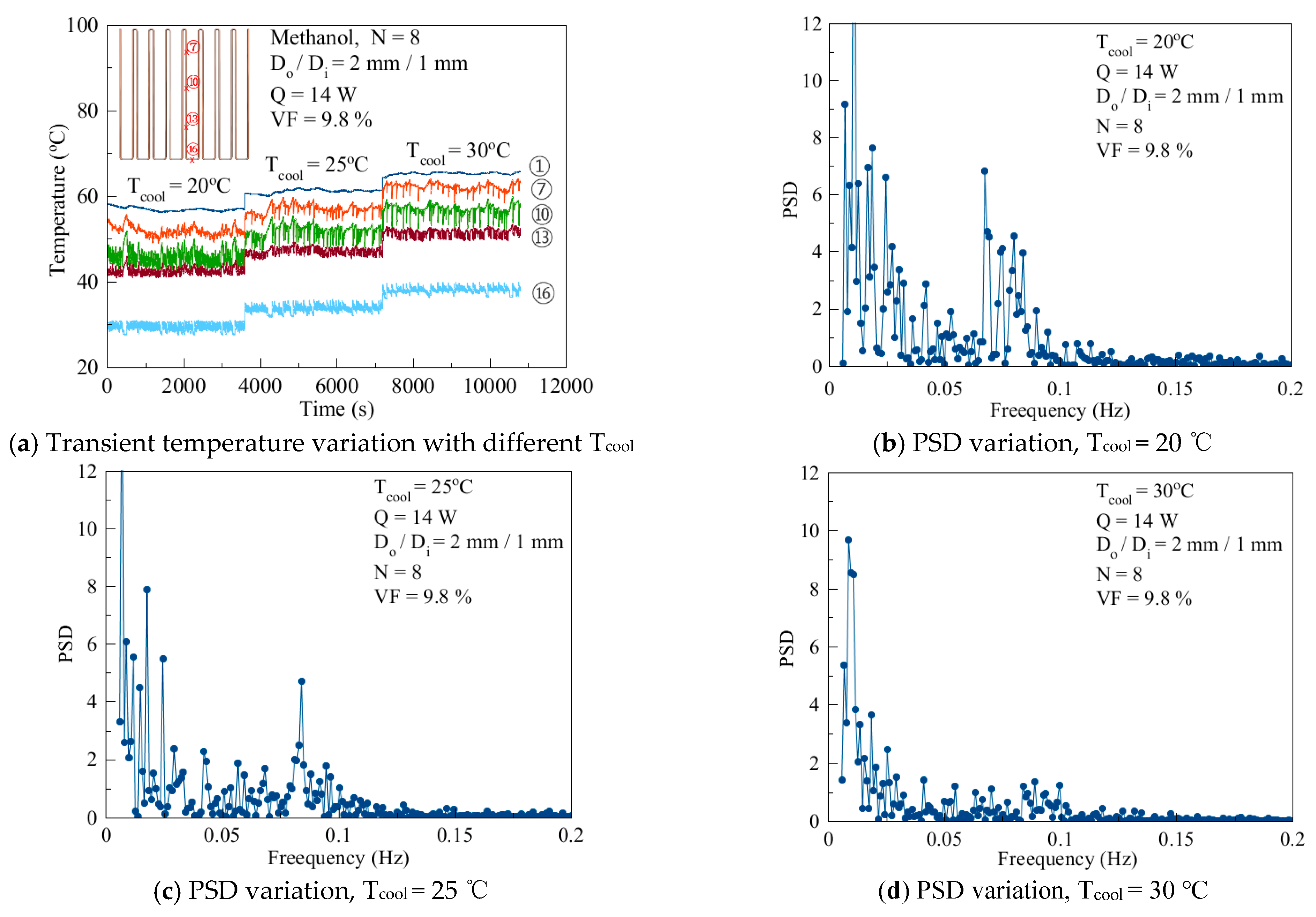
As shown in
Figure 8a–d, with a T
cool of 20 °C, the peak appeared near to 0.75 Hz and was relatively wide. When the T
cool rose to 25 °C (
Figure 8c), the peak was significantly narrower. When the T
cool continued to rise to 30 °C, not only did the peak disappear completely, PSD also decreased in the full frequency region. From this behavior, it can be understood that when the heating temperature increases or the coolant temperature decreases, the temperature difference will increase between the evaporation section and the condensation section. Thus, the pressure gradient also increases, the working fluid movement will be smooth, and larger PSD values will be distributed in the high frequency region.
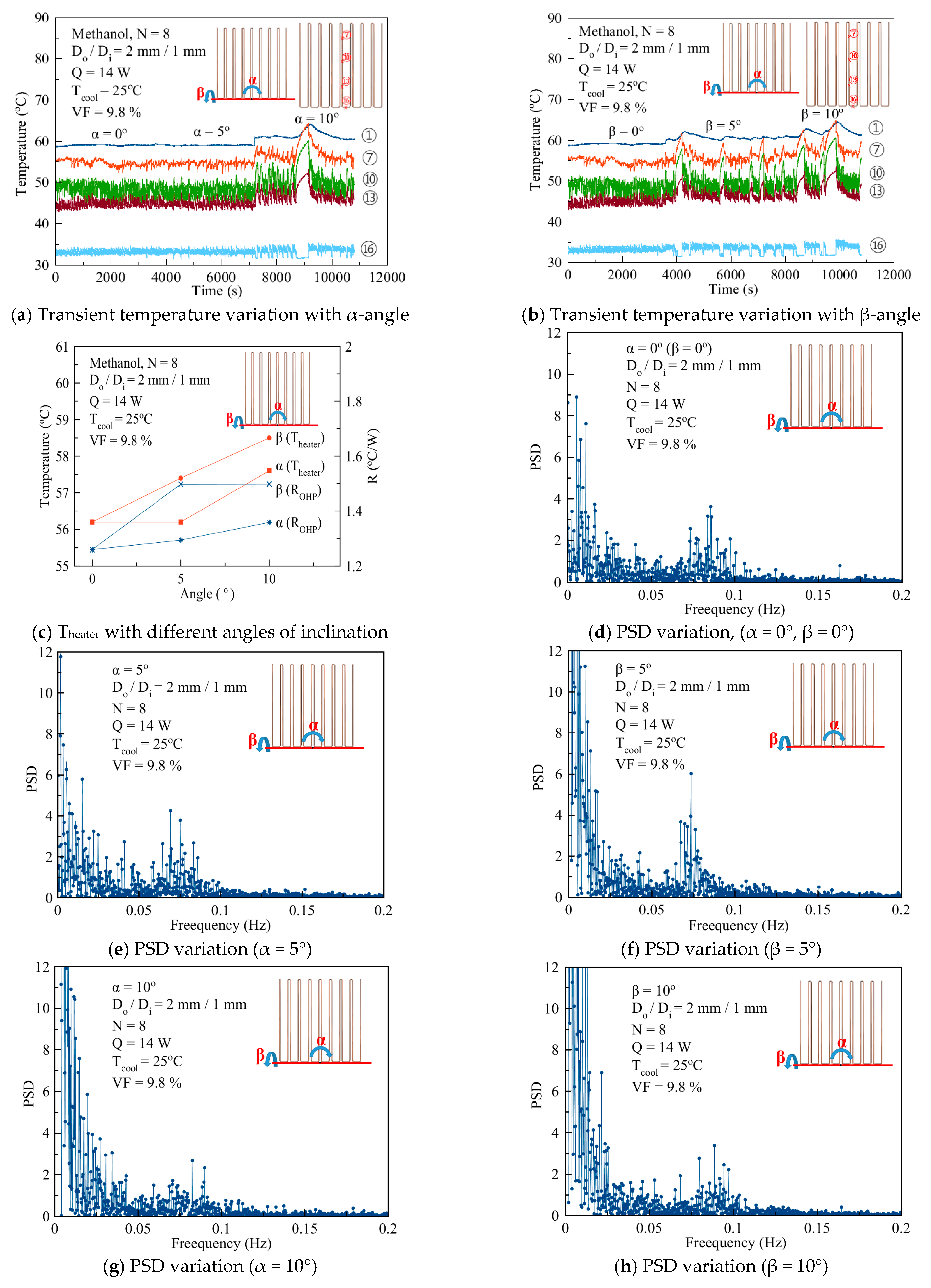
Figure 9 shows the experimental result with an orientation change of D
o/D
i = 2 mm/1 mm under the experimental conditions of a VF of 9.8%, a Q of 14 W, and a T
cool of 25 °C. When the α-angle was 0°, the peak frequency appeared between 0.075 and 0.1 Hz. When the α-angle increased to 5°, the peak moved to the low frequency region. After the α-angle had increased to 10°, the peak almost disappeared, and in the low frequency region, the PSD increased significantly. Similarly, when β increased, the peak value of PSD between 0.05 and 0.1 Hz gradually reduced, and due to the increase in intermittent oscillation, the PSD in the low frequency region increased. We know from this that as the α-angle (or β-angle) increases, intermittent oscillations occur, and larger values of PSD migrate from the high frequency region to the low frequency region and the thermal resistance increases. This is because the increase of the α-angle causes the gravity component g sin(α) to also decrease. However, because the α-angle can increase the uneven distribution of the head, it has a better performance than the β-angle.


