1. Introduction
The air-conditioning system (AC) is one of the most energy-demanding auxiliary loads in electric vehicles (EVs) that limits their driving range. In order to reduce the energy consumption, it is important to develop more energy-efficient AC systems, compact enough to be used in EVs.
Over the past century, conventional AC systems have been widely used for cooling and dehumidifying air. Although conventional AC systems are very efficient in cooling (sensible load), their performance in terms of humidity removal can be still enhanced (latent load). Indeed, these systems use cooling coils to remove the moisture from humid air by cooling the supply air below its dew point, which leads to an unnecessary and energy-expensive process on the air. Therefore in conventional AC systems, comfort conditions are not usually met in an energy-efficient way, especially in hot and humid climates [
1,
2].
To deal with the latent load more effectively, liquid desiccant cycles (LDCs) have been applied and integrated into HVAC systems [
3,
4,
5,
6]. In LDCs the humidity of supply air is absorbed in a devoted contactor by a liquid desiccant, in direct contact or through a semi-permeable membrane. While both approaches are energy-efficient in treating the latent load, the later one is more suitable to be adopted in EVs. Then, the absorbed water in the contactor is driven off in a second contactor (regenerator) and the desiccant concentration is restored [
7].
Despite the LDC´s advantageous functionality, its performance is largely affected by the temperature of liquid desiccant. In fact, due to the water vapor absorption (latent heat release) and heat transfer between the hot supply air and liquid desiccant, the temperature of liquid desiccant rises thus reducing the vapor absorption potential along the desiccant path. To deal with this issue, Isetti et al. [
7] drawn attention to the performance improvement of LDCs by designing and developing the first prototype of a combined membrane contactor, which is internally cooled by a refrigerant flow directly derived by a vapor compression cycle. Since then, there has been a growing number of experimental and numerical studies on the performance of internally cooled membrane-based dehumidifiers [
8,
9,
10,
11,
12].
However, despite the promising performance of the membrane contactors in dehumidification for air conditioning, these systems usually are too bulky to fit into limited spaces such as vehicles [
13]. Isetti et al. [
14] proposed an innovative compact Three-Fluid Combined Membrane Contactor (3F-CMC) as the core component of a LDC to dehumidify the air in an energy-efficient way. This cycle is integrated with a traditional vapor compression cycle (VCC) to form a climate-control system for serving in electric vehicles (EVs). In this 3F-CMC, liquid desiccant is internally cooled by means of the refrigerant that flows inside mini-tubes. The mini-tubes are located in the desiccant channel that is separated from the air stream by a semi-permeable membrane. These mini-tubes treat the sensible heat from the liquid desiccant and keep its temperature controlled, and accordingly, the water vapor absorption potential in an acceptable range. The above described 3F-CMC and the related hybrid climate control system have been developed up to technology readiness level (TRL) 6 in a successful H2020 project called XERIC. In the H2020 work programme, TRL 6 means “technology demonstrated in relevant environment (industrially relevant environment in the case of key enabling technologies)”.
In this paper, the performance of this core-component of a high-efficient innovative air-conditioning system for electric vehicles is deepen. In detail, a sensitivity analysis of the governing parameters is performed by adopting a 3D Computational Fluid Dynamics (CFD) model to simulate the conjugate heat and mass transfer inside the 3F-CMC. The numerical results for different operating conditions are validated by experimental measurements on a 3F-CMC prototype with good agreement. Both numerical and experimental results show noteworthy dehumidification performance of the compact 3F-CMC, especially for hot and humid conditions.
2. Description of the Experimental System
The 3F-CMC is composed by 11 repetitive elements assembled together and confined between two aluminum-closing plates. Each element is made of a male frame, a female frame, four U-shaped mini-tubes, one spacer. On each frame, a flat sheet of membrane of 0.034 m
2 (with a net working surface exposed to air of 0.03 m
2) is thermal welded, with the hydrophobic side facing the liquid desiccant. The membrane used was the D845, provided by GVS (Zola Predosa, Bologna, Italy); it is a PTFE membrane on a nonwoven support with liquid entry pressure (LEP) equals 3.4 bar, having a total thickness
and mean pore size
of nominal 165 and 0.24 μm, respectively. Inside the desiccant channel 20 (four U-shape tubes
five turns each) copper-alloy mini-tubes are located with the internal and external diameters equal 0.9 and 1.6 mm, respectively, as illustrated in
Figure 1 (bottom-right). In this figure and for a better understanding of the 3F-CMC device, just two modules are shown while closing plates are also included in the break-down view. Moreover, desiccant solution has co-counter-flow and cross-flow arrangements with refrigerant and airflows, respectively.
The experimental set up for the absorption tests, which has been built in TICASS’ laboratory, is sketched in
Figure 1. The 3F-CMC, which is shown in
Figure 1 (inside the green frame), is fed by two loops: one where the desiccant (LiCl aqueous solution-CAS N° 7447-41-8, CARLO ERBA Reagents S.r.l., Cornaredo (MI), Italy) flows and the second one crossed by chilled water coming from a thermostatic water bath; the latter has a high mass flow rate in order to simulate the refrigerant phase change. The desiccant is moved by a Fluid-o-Tech
® gear micro pump (Fluid-o-Tech s.r.l. Corsico, (MI), Italy) and its flow rate was measured by a DigiFlow
® Flow X3 ULF03.H.0 digital flowmeter (F.I.P. Formatura Iniezione Polimeri S.p.A, Genoa, Italy). The LiCl concentration was measured by means of probes sensible to the solution electric conductivity (BC Electronics
® ST3214, with a functional range up to 2000 ms). The water is moved to the 3F-CMC by the centrifugal pump of the thermostatic bath (ECO RE 2025, Lauda
®, Delran, NJ 08075) and its flow rate was measured by a second digital flowmeter DigiFlow
® Flow X3. Both loops were equipped with K thermocouples to measure temperatures at the inlet and outlet sections of the 3F-CMC. All measured data were recorded by a data-acquisition system including a multichannel scanner and a personal computer.
The air is aspirated by a centrifugal fan (SAIT Spa, Salò, Italy) whose rpm is controlled by an inverter (the data acquisition system was developed by Dafne S.r.l., Genoa, Italy) so that the mass flow rate can be varied in a wide range (from 50 m
3/h up to 300 m
3/h). The airflow is measured by a GWF
® (Macquarie Park NSW, Australia) turbine gas meter (working range: 20–400 m
3/h). At the 3F-CMC inlet, air RH and temperature can be varied by means of electric resistances and with an electronic controlled vapor source (IR33, Carel
®, Sha Tin, Hong Kong, China). Air RH and temperature are measured at the inlet and at the outlet of the 3F-CMC by thermo-hygrometric probes (Rotronic Italia S.r.l., Milan, Italy). Before data acquisition, the probes were calibrated against fixed points of RH obtained with LiCl and NaCl saturated solutions [
15]. The experimental uncertainties related to air temperature and RH measurements were respectively ±1% and ±2%.
3. Numerical Model
This section describes the adopted numerical approach to model the conjugate heat and mass transfer in one repetitive module of the 3F-CMC. Due to the complex flow behavior passing through this device, a fully 3D-CFD model was applied for both air and desiccant flows. In the 3F-CMC, heat transfer takes place among three flows, namely humid air, LiCl solution, and refrigerant, while water vapor is absorbed from humid air into LiCl aqueous solution through the membrane.
Figure 1 (bottom) illustrates a magnified segment (left) and a break-down view (right) of two repetitive elements of the 3F-CMC. In the current study, a half of one repetitive element is modeled, representing all the geometry details, as illustrated in
Figure 2. In fact, the computational domain includes two fluid zones (for air and desiccant), one solid zone (spacer), and the membrane (as a thin two-sided wall). To decrease the complexity of the problem the following assumption are made, while both desiccant and air flows are considered steady and laminar:
Absorbed vapor condenses into liquid water at the wetted membrane surface in the desiccant channel.
Dilution heat is ignored for the considered operating conditions.
The salt crystallization at the desiccant side and vapor condensation at the airside of the membrane are not considered.
The membrane is single-layer with a uniform distribution of pores.
Due to the phase-changing refrigerant flow inside the mini-tubes, their surface temperature is constant.
In this model, the conservation equations for the mass, momentum, and energy are solved for both humid air and desiccant solution, then:
where
, and
is the stress tensor [
16]. Furthermore, two diffusion-convection equations are solved for the mass fraction of water vapor, so-called the humidity ratio
, and condensed water
inside the air and desiccant channels, respectively:
Here
and
are diffusivity coefficients of water vapor and condensed water in air and the desiccant solution, respectively. The source terms used in Equations (1)–(5) are listed in
Table 1.
In
Table 1,
is the specific enthalpy,
is the specific heat,
is the reference temperature, and
represents the vapor volumetric mass flux rate through the membrane.
3.1. Water Vapor Transport Through the Membrane
The mass flux through the membrane is assumed to be due to the partial pressure difference of water vapor at the air and desiccant sides of the membrane. Then one can write [
7]:
Here
represents the water vapor transfer resistance coefficient through the membrane. In Equation (6)
is the mass flux per unit surface area on the membrane, related to the volumetric mass flux in the Equations (1)–(5) by
. Here
and
are, respectively, the volume and the surface area of the adjacent cells to the membrane (on both sides) where mass transfer takes place. In this model
is the partial pressure of the vapor in the air and
stands for the equilibrium partial pressure of water vapor at the interface of air/desiccant. This equilibrium partial pressure is a function of the mass fraction of LiCl in the solution
and its temperature
. For more detail, see the
Appendix A.
Vapor Transfer Resistance Coefficient
In the membrane-based dehumidification, water vapor passes through the membrane pores due to the partial pressure gradient on the both membrane sides, as a result of vapor absorption by the desiccant. This transport process corresponds to the rarefaction level of the gas inside the membrane medium, determined by Knudsen number (
). Knudsen number is defined as the ratio of the molecular mean free path
to a reference length as:
Here is the Boltzmann constant, is the mean pore size, is the average molecular diameter, and is the total pressure. When Knudsen number is small , the molecule-molecule collision is the dominant momentum transfer mechanism, and the gas molecules diffuse through the pores and microstructure of porous media as a result of inter-molecular collisions. When Knudsen number is high wall-molecule collisions occur more frequently than the gas molecule-molecule events and the gas diffuses due to the wall-molecule interactions, so-called “Knudsen diffusion”. For Knudsen numbers between these two regimes, both mechanisms for diffusion are important and contribute to the gas transport through the membrane.
While the hydrophobic membrane in the 3F-CMC is filled with stagnant air, both Knudsen and molecular diffusion contribute to the vapor transport through its porous structure, and one can assume separate contributions of the involved mechanisms with no direct coupling [
17]. Among different approaches that apply this assumption, Dusty Gas Model (DGM) [
18] and Schofield’s model [
19,
20] are widely used to describe the water vapor transport through membranes for different applications such as membrane distillation (MD) [
21,
22,
23,
24] and membrane contactors for dehumidification [
12,
17,
25]. In fact, these models take advantage of an electrical analogy in which the pressure gradient is the driving force and resistances against Knudsen and molecular diffusions function as electrical resistors in series circuits. Thus, one can write:
where:
Moreover, for a single-layer membrane, the tortuosity can be described as [
22]:
3.2. Boundary Conditions
The inlet and outlet boundary conditions in this study, for air and desiccant channels, are velocity-inlet and pressure-outlet, respectively. Moreover, the inlet and outlet of the air channel are extended enough to get a better convergence. In the current study, the Dirichlet boundary condition is imposed on mini-tubes´ surface with constant temperature. In addition, the membrane is reduced to a thin solid wall, in which both heat and mass fluxes are conserved. In both the membrane and spacer, heat is conducted through the solid zone while is coupled with the convection heat transfer by surrounding flows. Furthermore, the source terms listed in
Table 1 can be non-zero in the very first layer of meshes at both sides of the membrane.
3.3. Solution Scheme
In this paper, the conjugate heat and mass transfer of absorption dehumidification and cooling inside the 3F-CMC was simulated, by means of ANSYS-Fluent software (V. 18.1). Proper User Defined Functions (UDFs) and User Defined Scalars (UDSs) were developed to describe the diffusion-convection transport and source terms in the governing equations, while the pressure and velocity fields were coupled via the “coupled” algorithm. Mesh dependency was checked and the computational domain was meshed with
hexahedral cells.
Figure 2 (left-bottom) shows the generated mesh in a magnified cross section of the computational domain (2D view). The threshold criterion for the convergence was set to
.
4. Results and Discussion
4.1. Validation
Two series of experiments (A2 and A3), each one for different concentrations of LiCl solution, were conducted to investigate the performance of the 3F-CMC under various operating conditions, as listed in
Table 2. In addition, we also compared our numerical results with another set of experiments (A1) that was previously reported [
26].
The thermo-physical properties of the spacer, membrane, and LiCl solution used in the simulation are summarized in
Table 3. In this paper, in order to study the performance of the 3F-CMC, one effectiveness absorption parameter
and one effectiveness sensible parameter
are defined, respectively as the ratios between the actual removed moisture and decreased temperature to the maximum possible values, as discussed in [
27]:
Here
is the inlet equilibrium water vapor content at the interface between the air and desiccant solution.
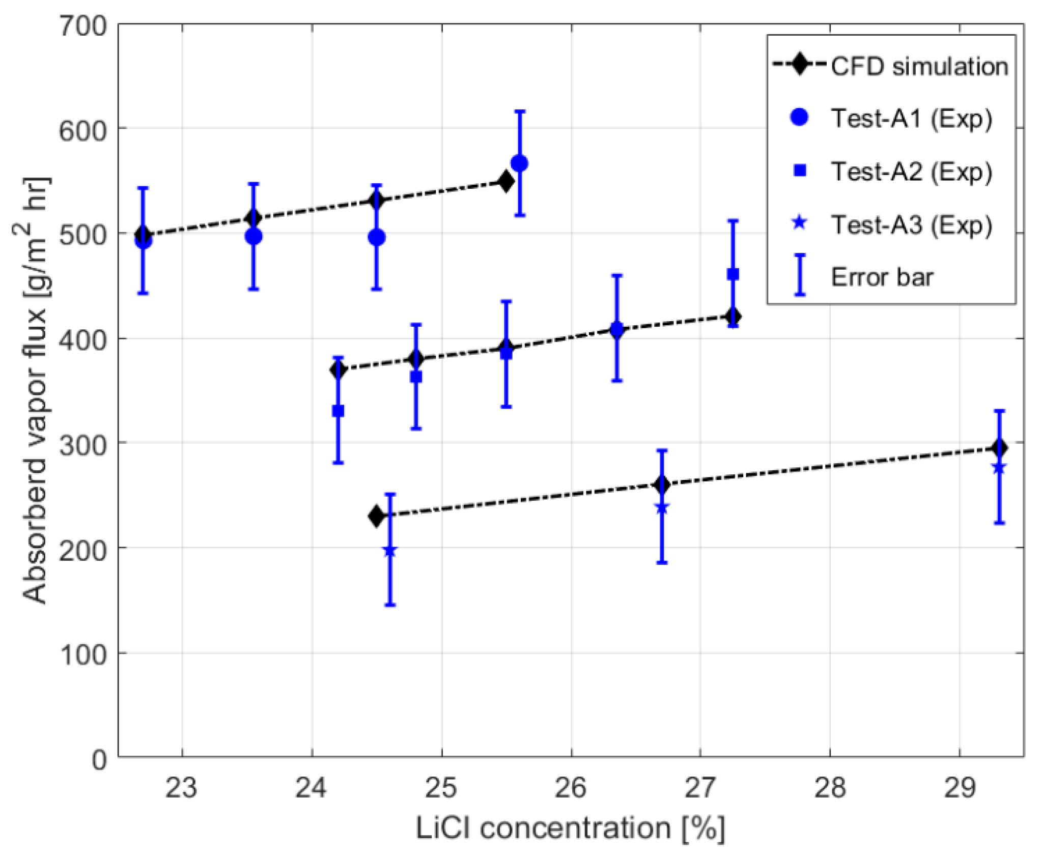
Figure 3 shows how the moisture absorption rate in the 3F-CMC changes under different operating conditions and LiCl concentrations for the three sets of experiments (A1, A2, and A3). The experimental results presented here report the absorbed vapor by liquid desiccant, while the amount of condensed water on the closing aluminum plates of the 3F-CMC were excluded and the error bar equals
. According to
Figure 3, CFD simulations can predict the absorbed water flux from humid air very well. As it is seen, by increasing the desiccant concentration, the affinity of the solution goes up steadily, leading to higher dehumidification rates for all cases.
4.2. Sensitivity Analysis
Having validated the CFD model, we numerically studied the 3F-CMC performance under different operating conditions. In this way, different parameters of the inlet air such as the humidity, flow rate, and temperature were investigated. Except for the investigated parameter, all studied cases had the same operating conditions as for Test A2, when the LiCl solution concentration was 25.5%.
Figure 4 illustrates how the pressure of the inlet airflow changes through the air channel in one cross section (indicated by a purple line in
Figure 2). As numerical results depict the pressure drop for the airflow, when
, is about 60 Pa which is quite satisfactory. Moreover,
Figure 5 shows the contours of the liquid desiccant velocity that is perpendicular to the airflow, while separated by means of the selective membrane. As it is evident, the desiccant velocity close to mini-tubes and especially on top of them is lower than in the rest of the desiccant channel. This might lead to a weaker convective term for condensed water at this zone in desiccant channel. It is worth noting that due to the complex geometry in the presence of a spacer in the air channel and mini-tubes in the desiccant channel a fully 3D model was applied; however, the plotted data hereafter report averaged values at the outlets.
4.2.1. Effects of the Inlet Air Humidity
Figure 6 illustrates the effect of the inlet humidity ratio
on the absolute moisture removal, absorption and sensible effectiveness parameters. As it is demonstrated the higher
, the higher moisture removal from the humid air. It is also evident that the moisture removal changes linearly with
.
According to this figure, for the considered operating conditions, the lowest corresponding under which the 3F-CMC device can still absorb water vapor from humid air is about 28%. Furthermore, on the one hand this figure shows that when % the absolute moisture removal is about 450% higher than that of with . On the other hand, the absorption effectiveness decreases dramatically for more humid air. It means that the 3F-CMC can reach up to 90% of the maximum possible vapor absorption (based on the inlet temperature of the desiccant) when , while this value drops to 45% for .
4.2.2. Effects of Desiccant Temperature and Flow Rate
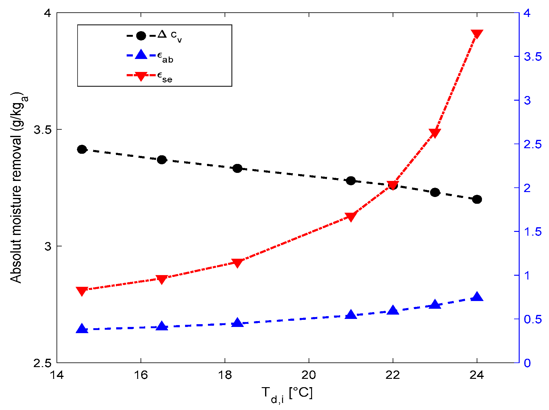
Figure 7 depicts how the inlet desiccant temperature affects the performance of the 3F-CMC and its absorption effectiveness. This figure shows that the desiccant temperature has a significant influence on its capacity to absorb water vapor. Even though the absorption effectiveness rises slightly by increasing the desiccant temperature, the absolute moisture removal declines, implying a noticeable degradation in the solution affinity for water vapor. As
Figure 7 indicates, a reduction in the inlet desiccant temperature by 9.4 °C enhances the moisture removal by 7%.
Figure 7 also demonstrates that by increasing the inlet temperature of desiccant, the 3F-CMC would remove sensible load more effectively and the sensible effectiveness rises dramatically.
According to Equation (13) and the operating conditions for Test A2, one can conclude that even though the inlet desiccant temperature went up from 14.6 to 24 °C, the outlet temperature of air increased just about 1.5 °C. This might be a result of an efficient heat transfer by the mini-tubes´ internal cooling that contributes mainly to the treatment of the sensible load; providing an increase in refrigerant mass flow rate.
Additionally,
Figure 8 presents the effects of the desiccant flow rate on the 3F-CMC performance. According to this figure, there is a plateau in the moisture removal, absorption, and sensible effectiveness for different desiccant flow rates, which was also reported by other researchers [
11]. In this way, the 3F-CMC might work with lower desiccant mass flow rates for the same dehumidification performance that means the energy needed for pumping would decrease.
4.2.3. Effects of the Inlet Air Temperature
As
Figure 9 displays, by increasing the inlet air temperature from 26.2 to 36 °C, the moisture removal declines by
, while the humidity ratio at the inlet is constant. It means that in contrast to the inlet humidity ratio, the inlet air temperature affects the absorption rate of the 3F-CMC just slightly, confirmed by the almost constant absorption effectiveness. Moreover, when inlet air temperature increases by 9.8 °C, the sensible effectiveness shows about 10% decrease, that according to Equation (13) corresponds to a small rise of the outlet air temperature, by 0.8 °C.
4.2.4. Effects of the Airflow Rate
Figure 10 shows that how the 3F-CMC performance changes with different airflow rates. As it is evident, the higher airflow rate, the less absorption effectiveness and absolute moisture removal per unit air mass
. However, thanks to the more air mass flow rate passing through the 3F-CMC, the total amount of the absorbed moisture rises, which is reported in
Figure 11. In fact, when the airflow rate passing through the 3F-CMC goes up from
to
, the amount of absorbed moisture increases by about 75%, while the absorption effectiveness and absolute moisture removal per
reduce about 56%. Moreover,
Figure 10 demonstrates that the sensible effectiveness decreases linearly by increasing the airflow rate. From this figure and Equation (13), it is concluded that the average temperature of the outlet air rises about 2 °C. Accordingly, we can infer that when higher airflow rates need to be treated, it would be more efficient to use more modules. In this way to choose the final number of modules used in the 3F-CMC, one needs to compromise between the 3F-CMC size and its efficiency, based on the process airflow rate.
5. Conclusions
In this paper, we studied the performance of a compact internally-cooled membrane contactor, designed for serving in EVs. This contactor, namely 3F-CMC, is the core-component of a hybrid climate-control system to treat the air humidity in an energy-efficient way. First, the numerical approach for simulating the conjugate heat and mass transfer inside the 3F-CMC was developed, by evaluating the vapor transfer resistance coefficient for the membrane. The numerical results show good agreement with experimental data under different operating conditions. Then, a sensitivity analysis was carried out to study how important is the effect of the following parameters on the 3F-CMC performance, namely: temperature, absolute humidity, and flow rate of the inlet air; temperature, concentration, and mass flow rate of the inlet liquid desiccant. The numerical results indicated that:
The absorption rate of the 3F-CMC was 450% higher when the inlet relative humidity went up from 37% to 75%, both for the same inlet temperature .
Passing higher airflow rates through the 3F-CMC would increase the absorbed vapor flux by desiccant; however, the absorption effectiveness would decrease. Thus, it is recommended to increase the number of modules of the 3F-CMC in order to treat higher flow rates and latent loads while preserving a high effectiveness.
The desiccant mass flow rate was the least influential variable on the absorption rate, which means that it is possible to reduce it without jeopardizing the performance of the 3F-CMC.
6. Patents
C. Isetti, S. Lazzari, E. Nannei, Italian Patent Application n° 102017000018072; “Contattore a membrana a tre fluidi perfezionato e impianto integrato di climatizzazione ad alta efficienza energetica utilizzante tale contattore”, filed 17/2/2017.
C. Isetti, S. Lazzari, E. Nannei, Italian Patent Application n° 102017000015758; “Impianto integrato di climatizzazione ad alta efficienza energetica”, filed 14/2/2017.
F. Boero, A. Bottino, G. Capannelli, C. Cattaneo, A. Comite, C. Isetti, Italian Patent Application n° 102018000004346, “Nuovi sistemi di protezione/rivestimento di materiali utilizzabili in varie applicazioni caratterizzate da ambienti chimicamente o fisicamente aggressivi attraverso la deposizione di strati nano-metrici sulla superficie esterna”, filed 4/10/2018.
Author Contributions
Conceptualization, E.A., O.I., and S.L.; methodology, E.A. and O.I.; software, E.A. and I.S.; validation, E.A., O.I., S.L., and F.B.; formal analysis, E.A., O.I.; investigation, E.A., O.I., S.L., and F.B.; data curation, F.B.; writing—original draft preparation, E.A.; writing—review and editing, E.A., O.I., and S.L.; visualization, E.A., I.S.; supervision, O.I, S.L.
Funding
This work is part of XERIC project that has received funding from the European Union’s Horizon 2020 research and innovation programme under grant agreement N°653605.
Conflicts of Interest
The authors declare no conflict of interest.
Nomenclature
| Specific heat of vaporization, |
| Thermal conductivity, |
| Molar weight of water vapor |
| The universal gas constant, ) |
| Velocity vector, |
| Greek symbols |
| Thickness, |
| Porosity |
| Dynamic viscosity, |
| Density, |
| Tortuosity |
| Subscripts |
| Air |
| Condensed water |
| Desiccant solution |
| Dry air |
| Inlet/out |
| Knudsen diffusion |
| Membrane |
| Molecular diffusion |
| Refrigerant |
| Spacer |
| Vapor |
| Water |
Appendix A
The water vapor equilibrium partial pressure for LiCl reads as [
28]:
where
is the saturation pressure for the water vapor:
and:
References
- Dai, Y.J.; Wang, R.Z.; Zhang, H.F.; Yu, J.D. Use of liquid desiccant cooling to improve the performance of vapor compression air conditioning. Appl. Therm. Eng. 2001, 21, 1185–1202. [Google Scholar] [CrossRef]
- Lambert, M.A.; Jones, B.J. Automotive adsorption air conditioner powered by exhaust heat. Part 1: Conceptual and embodiment design. Proc. Inst. Mech. Eng. Part D J. Automob. Eng. 2006, 220, 959–972. [Google Scholar] [CrossRef]
- Das, R.S.; Jain, S. Experimental performance of indirect aireliquid membrane contactors for liquid desiccant cooling systems. Energy 2013, 57, 319–325. [Google Scholar] [CrossRef]
- Yuan, W.; Yang, B.; Guo, B.; Li, X.; Zuo, Y.; Hu, W. A novel environmental control system based on membrane dehumidification. Chin. J. Aeronaut. 2015, 28, 712–719. [Google Scholar] [CrossRef]
- Isetti, C.; Nannei, E.; Magrini, A. On the application of a membrane air—liquid contactor for air dehumidification. Energy Build. 1997, 25, 185–193. [Google Scholar] [CrossRef]
- Abdel-Salam, A.H.; Simonson, C.J. Capacity matching in heat-pump membrane liquid desiccant air conditioning systems. Int. J. Refrig. 2014, 48, 166–177. [Google Scholar] [CrossRef]
- Isetti, C.; Nannei, E.; Orlandini, B. Three-fluid membrane contactors for improving the energy efficiency of refrigeration and air-handling systems. Int. J. Ambient Energy 2013, 34, 181–194. [Google Scholar] [CrossRef]
- Lun, W.; Li, K.; Liu, B.; Zhang, H.; Yang, Y.; Yang, C. Experimental analysis of a novel internally-cooled dehumidifier with self-cooled liquid desiccant. Build. Environ. 2018, 141, 117–126. [Google Scholar] [CrossRef]
- Annadurai, G.; Tiwari, S.; Maiya, M. Experimental performance comparison of adiabatic and internally-cooled membrane dehumidifiers. Int. J. Low-Carbon Technol. 2018, 1–10. [Google Scholar] [CrossRef]
- Huang, S.M.; Yang, M.; Hu, B.; Tao, S.; Qin, F.G.; Weng, W.; Wang, W.; Liu, J. Performance analysis of an internally-cooled plate membrane liquid desiccant dehumidifier (IMLDD): An analytical solution approach. Int. J. Heat Mass Transf. 2018, 119, 577–585. [Google Scholar] [CrossRef]
- Yang, Y.; Yang, M.; Huang, W.; Huang, S.M.; Ye, W.B.; Hong, Y.; Qin, F.G.F.; Shao, Y. Heat and mass transfer in an adjacent internally-cooled membrane-based liquid desiccant dehumidifier (AIMLDD). Energy Procedia 2017, 142, 3990–3997. [Google Scholar] [CrossRef]
- Woods, J.; Kozubal, E. A desiccant-enhanced evaporative air conditioner: Numerical model and experiments. Energy Convers. Manag. 2013, 65, 208–220. [Google Scholar] [CrossRef]
- Sahlot, M.; Riffat, S.B. Desiccant cooling systems: A review. Int. J. Low-Carbon Technol. 2016, 11, 489–505. [Google Scholar] [CrossRef]
- Isetti, C.; Nannei, E.; Lazzari, S.; Hariri, S.; Iliev, O.; Prill, T. New Climate-Control Units for More Energy-Efficient Electric Vehicles: The Innovative Three-Fluids Combined Membrane Contactor. In Proceedings of the 2017 Twelfth International Conference Ecological Vehicles and Renewable Energies (EVER), Monte Carlo, Monaco, 11–13 April 2017; pp. 1–5. [Google Scholar]
- Greenspan, L. Humidity fixed points of binary saturated aqueous solutions. J. Res. Natl. Bureau Stand. 1977, 81, 89–96. [Google Scholar] [CrossRef]
- ANSYS Fluent. Theory Guide; Ansys Inc.: Canonsburg, PA, USA, 2015. [Google Scholar]
- Zhang, L.Z. Mass Diffusion in a Hydrophobic Membrane Humidification/Dehumidification Process: The Effects of Membrane Characteristics. Sep. Sci. Technol. 2006, 41, 1565–1582. [Google Scholar] [CrossRef]
- Mason, E.A.; Malinauskas, A.P. Gas Transport in Porous Media: The Dusty-Gas Model; Churchill, S.W., Ed.; Elsevier: New York, NY, USA, 1983. [Google Scholar]
- Schofield, R.W.; Fane, A.G.; Fell, C.J.D. Gas and vapour transport through microporous membranes. II. Membrane distillation. J. Membr. Sci. 1990, 53, 173–185. [Google Scholar] [CrossRef]
- Schofield, R.W.; Fane, A.G.; Fell, C.J.D. Gas and vapour transport through microporous membranes. I. Knudsen-Poiseuille transition. J. Membr. Sci. 1990, 53, 159–171. [Google Scholar] [CrossRef]
- Martínez, L.; Florido-Díaz, F.J.; Hernandez, A.; Pradanos, P. Characterisation of three hydrophobic porous membranes used in membrane distillation: Modelling and evaluation of their water vapour permeabilities. J. Membr. Sci. 2002, 203, 15–27. [Google Scholar] [CrossRef]
- Srisurichan, S.; Jiraratananon, R.; Fane, G.A. Mass transfer mechanisms and transport resistances in direct contact membrane distillation process. J. Membr. Sci. 2006, 277, 186–194. [Google Scholar] [CrossRef]
- Rao, G.; Hiibel, S.R.; Childress, A.E. Simplified flux prediction in direct-Simplified flux prediction in direct-contact membrane distillation using a membrane structural parameter. Desalination 2014, 351, 151–162. [Google Scholar] [CrossRef]
- Fan, H.; Peng, Y. Application of PVDF membranes in desalination and comparison of the VMD and DCMD processes. Chem. Eng. Sci. 2012, 79, 94–102. [Google Scholar] [CrossRef]
- Das, R.S.; Jain, S. Performance characteristics of cross-flow membrane contactors for liquid desiccant systems. Appl. Energy 2015, 141, 1–11. [Google Scholar] [CrossRef]
- Isetti, C.; Nannei, E.; Lazzari, S.; Cerrai, B.; Nari, S. XERIC climate-control system for energy-efficient electric vehicles: First experimental results and numerical evaluation of the overall performance. In Proceedings of the 2018 Thirteenth International Conference on Ecological Vehicles and Renewable Energies (EVER), Monte Carlo, Monaco, 10–12 April 2018; pp. 1–6. [Google Scholar]
- Qi, R.; Lu, L.; Yang, A.H. Development of simplified prediction model for internally cooled/heated liquid desiccant dehumidification system. Energy Build. 2013, 59, 133–142. [Google Scholar] [CrossRef]
- Conde-Petit, M.R. Aqueous Solution of Lithium and Calcium Chlorides: Property Formulations for Use in Air Conditioning Equipment Design; M. CONDE ENGINEERING: Zurich, Switzerland, 2014. [Google Scholar]
Figure 1.
(Top) Scheme of the experimental setup for absorption test showing the 3F-CMC prototype in the green frame. (Bottom) A magnified section (left) and a break-down view (right) of two modules of the 3F-CMC Computer Aided Design (CAD), illustrating the air and solution channels, spacer (in green), mini-tubes (in gray), membranes (in red), closing plates, and frames (in blue).
Figure 2.
(Left-Top) Top view of the computational domain, illustrating the airflow direction (in orange), desiccant flow direction (in yellow), and Spacer (in green). (Right) shows a longitudinal cross section where the purple line indicates (dimensions are in mm). In this view, the air domain is in orange, spacer is in green, desiccant domain is in yellow, and blue shows the frame. (Left-Bottom) illustrates one magnified section of the longitudinal cross section, showing two fluid domains separated by membranes (in red), spacer, and outer surface of mini-tubes (in grey), where the desiccant flow is normal to the airflow.
Figure 3.
Experimental data vs. CFD simulation.
Figure 3.
Experimental data vs. CFD simulation.
Figure 4.
Airflow streamlines colored by pressure [Pa] through an air channel (arrow shows the airflow direction).
Figure 4.
Airflow streamlines colored by pressure [Pa] through an air channel (arrow shows the airflow direction).
Figure 5.
Velocity [mm/s] contours in the desiccant channel (arrow shows the desiccant flow direction).
Figure 5.
Velocity [mm/s] contours in the desiccant channel (arrow shows the desiccant flow direction).
Figure 6.
Effects of the inlet humidity on the absolute moisture removal, absorption, and sensible effectiveness parameters.
Figure 6.
Effects of the inlet humidity on the absolute moisture removal, absorption, and sensible effectiveness parameters.
Figure 7.
Effects of the temperature of the inlet LiCl solution on the absolute moisture removal, absorption, and sensible effectiveness parameters.
Figure 7.
Effects of the temperature of the inlet LiCl solution on the absolute moisture removal, absorption, and sensible effectiveness parameters.
Figure 8.
Effects of the solution flow rate on the absolute moisture removal, absorption, and sensible effectiveness parameters.
Figure 8.
Effects of the solution flow rate on the absolute moisture removal, absorption, and sensible effectiveness parameters.
Figure 9.
Effects of the temperature of the inlet air on the absolute moisture removal, absorption, and sensible effectiveness parameters.
Figure 9.
Effects of the temperature of the inlet air on the absolute moisture removal, absorption, and sensible effectiveness parameters.
Figure 10.
Effects of the airflow rate on the absolute moisture removal, absorption, and sensible effectiveness parameters.
Figure 10.
Effects of the airflow rate on the absolute moisture removal, absorption, and sensible effectiveness parameters.
Figure 11.
Effects of the airflow rate on the absorbed vapor flux by the 3F-CMC.
Figure 11.
Effects of the airflow rate on the absorbed vapor flux by the 3F-CMC.
Table 1.
Source term used in the governing equations.
Table 1.
Source term used in the governing equations.
| Source Term | Value |
|---|
| |
| |
| |
| |
| |
Table 2.
Operating conditions for the experiments.
Table 2.
Operating conditions for the experiments.
| Test | | | | | | | |
|---|
| A1 [26] | 66 | 20 | 63 | 17.4 | 30.5 | 15.1 | 17.1 |
| A2 | 66 | 20 | 68 | 14.6 | 26.2 | 14.6 | 18.3 |
| A3 | 66 | 20 | 61 | 10.1 | 22.0 | 11.6 | 12.2 |
Table 3.
Spacer, membrane, and desiccant properties.
Table 3.
Spacer, membrane, and desiccant properties.
| Domain | Parameter | Value | Domain | Parameter | Value |
|---|
| Spacer | | | Membrane | | |
| | | | | | |
| | | | | | |
| Desiccant | | | | | |
| | | | | | 0.63 |
| | | 3100 | | | |
| | | | | | |
© 2019 by the authors. Licensee MDPI, Basel, Switzerland. This article is an open access article distributed under the terms and conditions of the Creative Commons Attribution (CC BY) license (http://creativecommons.org/licenses/by/4.0/).


