1. Introduction
Currently, techniques for addressing water scarcity and power shortage issues are largely being applied separately in geothermal fields, while the initiative to solve the twin problems together is increasingly being pursued. Most of the high-temperature geothermal energy (>200 °C at 1 km depth) is traditionally exploited through power plants using well-proven technologies like steam systems and single/double flash systems [
1,
2]. Meanwhile, low-temperature geothermal energy can be optionally used for desalination and freshwater generation, and extra desalination systems are normally needed [
3].
As for power generation in the geothermal energy field, the single-flash plant is the most common power plant installed at a newly developed liquid-dominated fields, and the steam plant is always the first choice in fields where the geofluids have higher vapor quality [
4]. In the steam system (SS), vapor and liquid in the original high temperature geothermal fluid is separated directly after discharged from the wellhead; in the single-flash system (SFS), high-temperature geothermal water is directed into a flashing vessel where the two-phase geofluid is flashed and vapor and liquid are separated. The separated geothermal liquid is then reinjected back into the field while the vapor is passing through an expander and generator for power generation. However, irreversibilities associated with both the separating process of the steam system and the flashing process of the single-flash system are inevitable [
5]. To address this issue, the total flow expansion concept is worthy of further investigation. A trilateral flash system (TFS) which would process the wellhead discharge directly for expansion and power generation through a total flow turbine is thus proposed.
The motive of total flow expansion development comes from the idea of avoiding irreversibilities in the flashing and separating processes of traditional geothermal systems. The US Lawrence Livermore Laboratory [
6] proposed the total flow concept and developed it in the 1970s and 1980s, and a single-stage pure impulse turbine was designed and tested to recover energy from geothermal hot brine deposits. The best efficiency tested from the prototype in lab was 23%, and it was estimated to reach 45% with full-admission conditions [
7]. Another type of total flow expander, a rotary separator turbine, was proposed and designed for biphase geothermal fluid by Cerini et al. [
8]. Extensive tests were conducted and an efficiency of 27% was obtained at part load. Screw expanders have also been used as total flow devices for steady intermittent processes [
9] and a 50 kW industrial system had been manufactured and operated by Electratherm Inc. in a number of installations [
10]. In recent years, Akbarzadeh et al. [
11] researched a combined power–water generation system in both a solar energy and geothermal energy field. They started by proposing a system for simultaneous desalination and power generation based on the trilateral flash cycle (TFC). Compared to traditional power cycles, the trilateral flash cycle can more effectively utilize most of the energy available in low/medium grade heat sources. After expansion steam is condensed into freshwater and stored instead of being abandoned [
12]. Later, they proposed two-phase nozzle design and conducted research on total flow expansion devices, targeting low temperature and low vapor quality geothermal water in Australia. By upgrading the expansion device from a two-arm rotor to reaction turbines, the performance of the system has been improved significantly, demonstrating the good potential of the combined power and water generation concept [
13].
As for water desalination, freshwater generation in geothermal fields has been researched on a theoretical basis for many years [
3]. In most proposed designs, either the geothermal water was directly used to drive the desalination device or the exhaust heat of geofluid after power generation was used to accomplish the desalination. Savvina, L. et al. [
14] conducted a techno-economic analysis of a desalination system driven by low-enthalpy geothermal energy. Both direct use and indirect use of geofluid for desalination were investigated. Calise, F. et al. [
15,
16] proposed a novel polygeneration system for electricity, desalinated water, and space heating and cooling generation utilizing both solar and geothermal energy. Dynamic simulation and thermo-economic analyses were conducted for short-term and long-term operations, and the desalination subsystem has a relatively low cost. A case study on the hybrid system in Pantelleria Island was then presented, indicating that the system is capable of covering the fresh water demands of the island in addition to its power and heating/cooling output [
17].
Geothermally driven desalination is proven to be a promising technique in both stand-alone systems and multipurpose systems with integration of power generation subsystems. In smaller scale geothermal fields, an easier and more flexible way of water harvesting is to condense the exhaust steam from turbine outlet into freshwater. A similar design has been investigated by Khaghani [
18]. Total flow technology was realized by a reaction turbine for geothermal energy to generate power as well as fresh water, and the average fresh water production was estimated to be ~7.5% of the feed water flow rate.
As geothermal resources are abundant in geothermal fields like Aluto Langano of eastern Africa, instead of merely being used for electrical power or being equipped with complex subsystems for multipurpose outputs, it can be utilized for freshwater harvesting through a steam condensation process after expansion, without adding extra desalination devices.
Looking back at similar design strategies for combined power–water generation, the concept of combined power and freshwater generation without adding subsystems is by now rather new for geothermal application. Based on these considerations, a new design strategy for combined power and freshwater generation is proposed for the geothermal energy utilization. In this work, two typical high-temperature geothermal wells are firstly chosen as heat sources from the Aluto Langano geothermal field of Ethiopia. On the basis of practical analysis of wellhead conditions, three combined power–freshwater generation configurations are proposed and investigated. Two of them are slightly modified from traditional steam system (SS) and single-flash system (SFS), while the third one is a trilateral flash system (TFS), which is rather novel in this field. Performance parameters investigated include the power generation ability, system efficiency, freshwater generation capacity, as well as the system energy saving potential.
2. Heat Source Analysis—Geothermal Well Information
The geothermal wells under investigation are located in the Aluto Langano geothermal field of Ethiopia, which is grouped as a liquid-dominated geothermal field in eastern Africa [
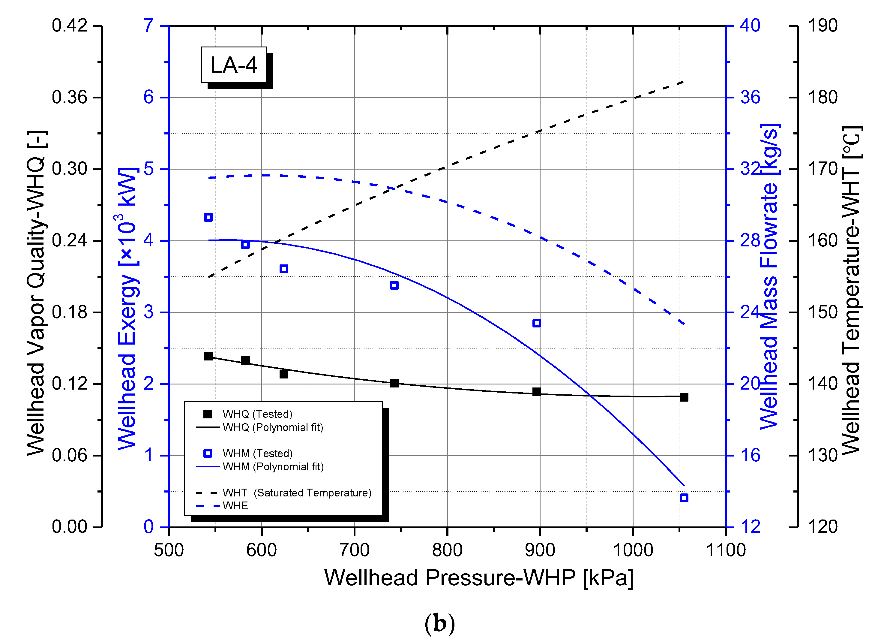
19]. Two typical and active geothermal wells—LA-8 and LA-4—were chosen as the targeted heat sources for the energy utilization systems. Both of them have two-phase, liquid-dominated wellhead discharges, and the discharge data from wellhead tests are gathered and analyzed in
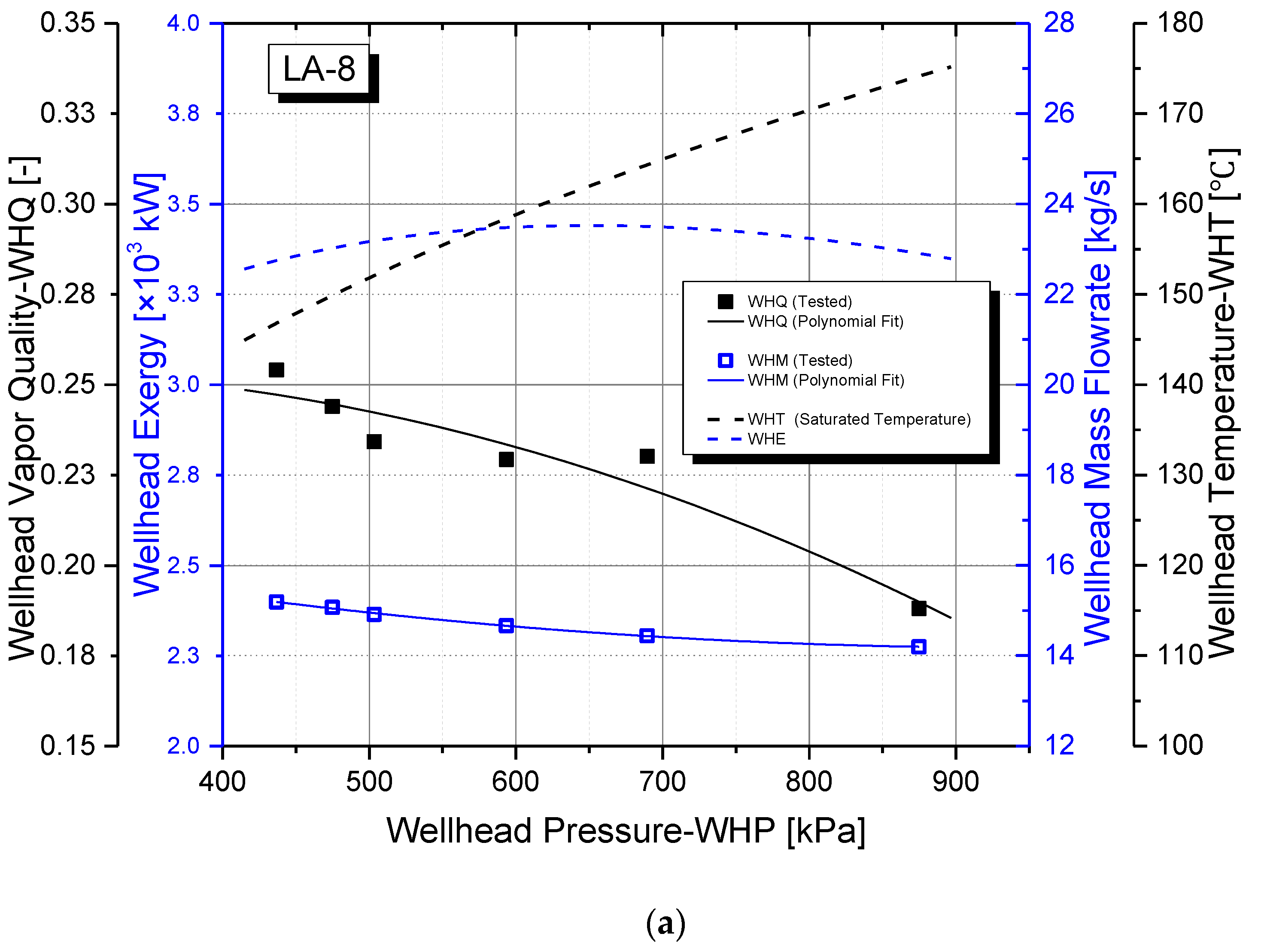
Figure 1. Wellhead vapor quality (WHQ) and wellhead mass flow rate (WHM) are tested in situ [
19]. Applying the data and empirical methodology [
20], polynomial curves are fitted to the test points to correlate the well flow data to corresponding wellhead pressures to better show the discharge profile. Besides, the wellhead temperature and geofluid exergy is calculated based on the pure water properties in REFPROP [
21], ignoring other geofluid constituents with small proportions. The wellhead discharge data provide operating conditions for the proposed systems.
The two wells—LA-8 and LA-4—have similar wellhead pressure ranges and similar production variations within these pressure ranges. Wellhead vapor qualities and flow rates continually reduce as the head pressure increases. However, they have their respective characteristics in terms of the production scale and thermal water vapor quality. Firstly, the vapor quality of LA-8 is mostly within the range of 0.19 to 0.25, which is approximately twice as large as that of LA-4 (0.1~0.14), meaning that LA-4 is more liquid-dominated than LA-8. Secondly, wellhead mass flow rate (WHM) discharged from LA-4 is much higher than that from LA-8, as the blue squares and lines in
Figure 1 show. As wellhead pressure increases, WHM of LA-8 decreases slightly from 15.4 kg/s to 14.2 kg/s, while that of LA-4 drops from 28.0 kg/s to 14.3 kg/s, indicating that LA-8 has much smaller yet steadier discharge. As demonstrated by the property calculations, both wellhead temperatures of LA-8 and LA-4 are increasing within the 140 to 180 range, grouping them as low–medium enthalpy geothermal resources. Furthermore, as the blue dashed lines represent, the exergy of wellhead geofluid (WHE) is between 3.3 × 10
3 kW and 3.5 × 10
3 kW and 2.8 × 10
3 kW and 4.9 × 10
3 kW for LA-8 and LA-4, respectively. Comparing to that of LA-8, higher exergy of geofluid is calculated under most LA-4 conditions mainly because of its larger mass flow rate. The exergy level indicates the energy capacity of each geothermal well.
3. System Configuration and Modeling
3.1. System Description
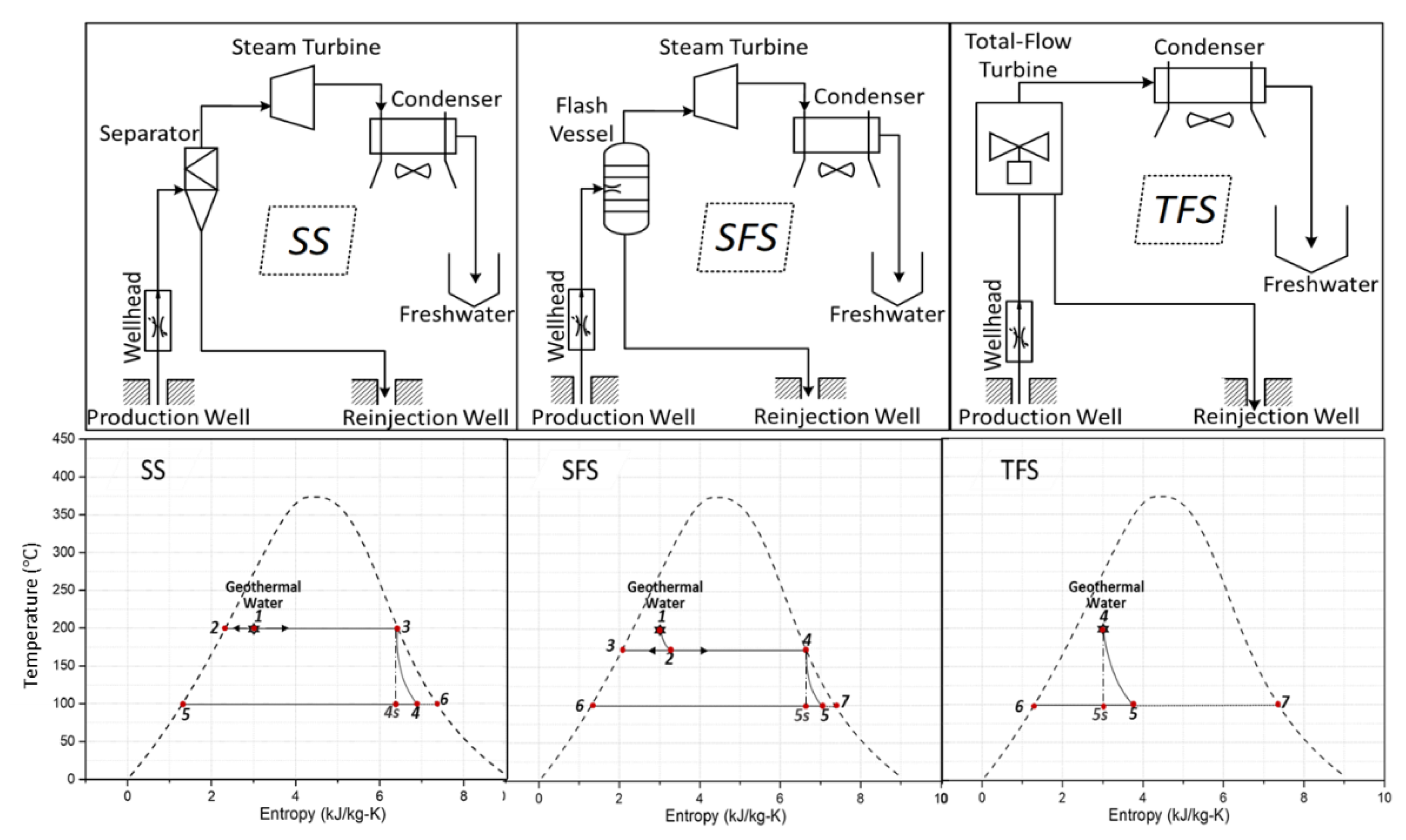
The three geothermally sourced systems proposed for combined power and freshwater generation are configured and illustrated in
Figure 2, including a steam system (SS), a single-flash system (SFS), and a trilateral flash system (TFS). The corresponding temperature–entropy diagrams of the three systems are attached right below their configurations. As shown in the figures, the first two traditional power systems are mostly similar to each other, except that a separator is applied in SS while a flash vessel is adopted in SFS. The flash vessel is a 2-in-1 device that accomplishes both flow flashing and liquid/steam separating processes.
For the trilateral flash system (TFS), geothermal water from the wellhead is introduced to the designed total flow turbine directly [
22]. Less processes and components are needed in this system comparing to the other two. Brine water and steam after expansion are separated in a specially designed turbine housing, with steam flowing upwards through the condenser for freshwater production while the brine water flows back to reinjection well due to gravity.
Moreover, instead of directly reinjecting the condensed water to geothermal reservoirs or discharging it to the environment in the form of coproduced brine and/or uncondensed steam, the desalinized freshwater during condensation is wholly recovered by the proposed three systems.
3.2. Modeling Assumptions
Some assumptions are needed before the system modeling:
The separation process is modeled as an isobaric process with constant pressure.
Any change in the kinetic or potential energy of the fluid is neglected as it undergoes a flashing process or an expansion process through the turbine.
Heat loss from the turbines is neglected.
3.3. Steam System (SS) Modeling
The key process for a steam system is the expansion in turbine, i.e., from points 3 to 4 as shown in
Figure 2. It should be noted that the occurrence of moisture during the expansion process would reduce turbine efficiency. According to the Baumann rule [
23], an average moisture percentage of 1% reduces the turbine efficiency by roughly 1%. Even though the turbine inlet flow is saturated vapor with zero moisture, as the expansion starts, the steam turbine operates mostly in the two-phase region, thus degradation in performance caused by moisture should be taken into account. Adopting the Baumann rule, the turbine efficiency
ηt is given by
ηtd is the dry turbine efficiency which is conservatively assumed to be constant at 85%; x3 (= 1) and x4 denote the vapor qualities of inlet and outlet flows of the steam turbine, respectively.
The ideal turbine outlet state would be used to get the thermodynamic state of point 4, which is in return determined by turbine efficiency, as shown in
Figure 2, fluid properties at state 4 s.
h4s is the enthalpy of state 4s, which can be calculated from the known pressure and entropy values (s4s = s3). Otherwise, h4s can be directly obtained from the REFPROP database with input of the known pressure and entropy values. Both methods share the same principle and thus yield the same h4s output.
Adopting the Baumann rule, the enthalpy of the turbine outlet state 4 can be obtained:
Then, the vapor quality x4 is obtained from the condensing pressure and entropy value h4.
Therefore, the power produced by the turbine per unit mass of steam flowing through it is given by
Freshwater is harvested from the condenser through the steam condensation process. For a steam system, the mass flow rate ratio of freshwater to heat source is the vapor quality of the wellhead geofluid since it is directly separated when discharged, and the freshwater mass flow rate is easily obtained.
When the steam exits from the turbine outlet, either mechanical air-cooling or natural draft air-cooling techniques can be adopted for condensation. The natural draft air-cooling research enhanced by thermal chimney concept is now under development [
24].
By adopting a reasonable energy consumption rate for up-to-date desalination technology (
), the freshwater generated from the thermal systems can be converted into equivalent energy savings:
3.4. Single-Flash System (SFS) Modeling
Comparing with steam system, the single-flash system has a flashing process occurring at constant enthalpy before the liquid/steam separation and steam expansion processes, as demonstrated in
Figure 2.
For a traditional SFS designed for a saturated liquid heat source, there is a ‘rule of thumb’ about the optimal temperature of state 2 which determines the separation temperature as well as the inlet flow state of turbine [
5]. According to the ‘rule of thumb’, the optimum power output occurs when the separator temperature is close to the average temperature between the heat source and heat sink. However, calculations show that the rule is no longer applicable with the two-phase heat source in this work, since the optimum performance is not obtained at the average temperature state. In order to obtain the optimum temperature and the corresponding optimal performance, the system performance of a SFS is thus modeled by decreasing the temperature of state 2 from wellhead temperature to condensing temperature by a small temperature step of 0.1 °C, and the optimal separation temperature and system performance are therefore accurately obtained.
Apart from the modeling of the liquid/steam separation process, the steam expansion process and condensation are the same as those of a steam system.
3.5. Trilateral Flash System (TFS) Modeling
Modeling of the novel trilateral flash system is quite simple since only two processes are included and average turbine efficiency is preset as constant. Detailed equations of each process in each system are listed in
Table 1. It should be noted that all the subscripts of parameters in this table are corresponding to those in
Figure 2. The zero-dimensional approach-based programming and data processing are accomplished in MATLAB environment.
3.6. Modeling Validation
The three models of steam system (SS), single-flash system (SFS), and trilateral flash system (TFS) have been validated against previous work in the literature, as shown in
Table 2. The very close correspondence of the model results to the referenced instances demonstrates the viability of the models presented here. Working conditions of the current models were changed accordingly to those in references and very small deviations were obtained. The reason for the slight deviation originates from different property databases applied. The property database in the current work is from REFPROP.
3.7. Simulation Description
With the above preparation, three systems are simulated under variable wellhead conditions. The input geofluid data for the models are fully displayed in
Figure 1 for both LA-8 and LA-4, including the wellhead vapor qualities, mass flow rates, temperatures, and pressures.
As for the three thermal systems, the power generation performance is primarily determined by the turbine efficiency and inlet flow state. So far, no total flow turbines are commercially available for geothermal application [
25], but previous and ongoing research has indicated its promising potential [
13,
22]. Four average total flow turbine efficiencies (
ηtave) have been conservatively set as 20%, 30%, 40%, and 50% for the trilateral flash system (TFS) according to previous investigations in similar applications [
26]. The turbine inlet enthalpy of TFS equals to the enthalpy of wellhead flow because of its total flow characteristic. Average dry expansion efficiencies for both steam turbines in SFS and SS are both conservatively set as 85% [
5].
To avoid vacuum and system complexity, the condensation is designed to be conducted at atmosphere pressure, so the freshwater recovered has a near-boiling temperature of 100 °C.
4. Results and Analysis
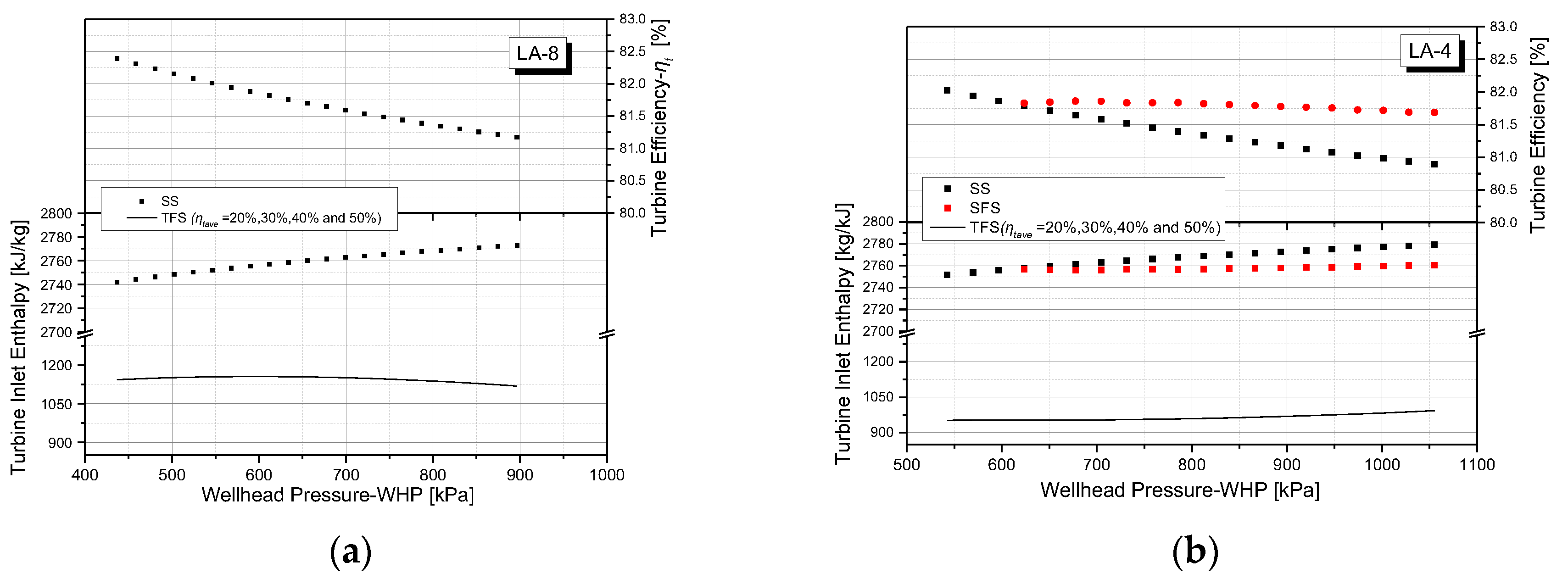
4.1. Principal Influence Factors of System Performance.
For the single-flash system (SFS), the flow mixture after flashing is separated into vapor and brine liquid. There generally exists an optimal separating temperature to obtain the best thermodynamic performance if the heat source is saturated liquid [
5]. However, this rule is not applicable when the heat source is a two-phase mixture, so the optimal separation temperature and system performance are sought through modeling, as illustrated in
Section 3.4 above. Simulations under LA-8 conditions show that the system performance (power generation) keeps decreasing as the separation temperature decreases from wellhead temperature to the temperature near condensation, and no optimal performance occurs during this process. This means that the best power generation occurs when the vapor and liquid are separated directly after being discharged from wellhead and no flash process is actually needed. Hence, the single-flash system (SFS) becomes a steam system (SS).However, the optimal separation temperature occurs when wellhead pressure is higher than 600 kPa under LA-4 conditions. So a SFS will only be applied under these conditions and is ploted in red dots in
Figure 3b). The turbine wet efficiency of SFS decreases slightly as the well heat pressure increases from 600 kPa to 1055 kPa.
For the steam system (SS), turbine wet efficiency keeps decreasing as the wellhead pressure increases, as shown in
Figure 3a,b. The reason is that turbine inlet vapor quality is always 1, while the outlet vapor quality decreases as the wellhead pressure increases, since the dry expansion efficiency is fixed. According to the Baumann rule, vapor quality is an essential parameter to determine the turbine wet efficiency. Therefore, the increasing wetness of turbine outlet flow reduces turbine efficiency. Besides, the turbine inlet enthalpy of SS keeps increasing as the wellhead temperature and pressure both increase. Compared to that of the steam system, the turbine efficiency of SFS is higher and steadier [
27].
Besides, the turbine inlet enthalpy of steam system (SS) keeps increasing under both wells’ conditions as the wellhead temperature and pressure increase, and it is ~2–3 times higher than that of the trilateral flash system (TFS) since the inlet flow contains only vapor of SS as well as SFS while the total flow turbine inlet contains a large propotion of low-enthalpy liquid. It should also be noted that, turbine inlet enthalpy of trilateral flash system (TFS) under LA-8 conditions is ~15–20% higher than that of LA-4 because LA-8 is less liquid-dominited.
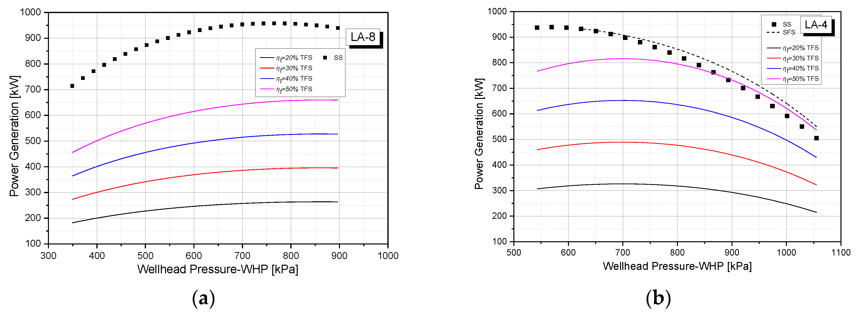
4.2. System Performance: Power Generation
Under LA-8 conditions, the steam system (SS) is superior to the TFS in terms of power generation capacity. As
Figure 4a shows, its power output changes within 714.7 kW to 958.0 kW under the wellhead pressure range. However, the maximum power output of trilateral flash system (TFS) with a turbine efficiency of 50% is only 659.6 kW, which is 45.2% lower than that of SS. The efficiency of the total flow turbine mainly determined the power generation ability of the TFS, indicating that higher efficency (>50%) is needed for TFS in order to be competitive with the traditional steam system for heat sources like LA-8.
However, the power output scenario is different under LA-4 conditions. As demonstrated in
Figure 4b, a total flow turbine with an efficiency of 50% makes the trilateral flash system (TFS) comparable with the steam system (SS) and single-flash system (SFS) regarding power generation, especially when the wellhead pressure is higher than 800kPa. Besides, the comparison of (a) and (b) in
Figure 4 reveals that changing the geothermal well from LA-8 to LA-4 would improve the power generation of the TFS by 15 to 30% attributes to the mass flow rate increase.
On the other hand, the power changing tendencies under two heat source conditions are different. Basically, the increase of wellhead pressure and temperature tends to increase the turbine inlet enthalpy, while the decrease of wellhead quality tends to reduce it, and the decreasing mass flowrate tends to reduce the power output. In summary, the power generation trends are consequently formed by the interactions of these three factors. As a result, the power generation of two systems under LA-8 conditions mostly show an increasing trend. However, under LA-4 conditions, the power generation of the two traditional systems keep decreasing while that of the trilateral flash system (TFS) changes in parabolic patterns.
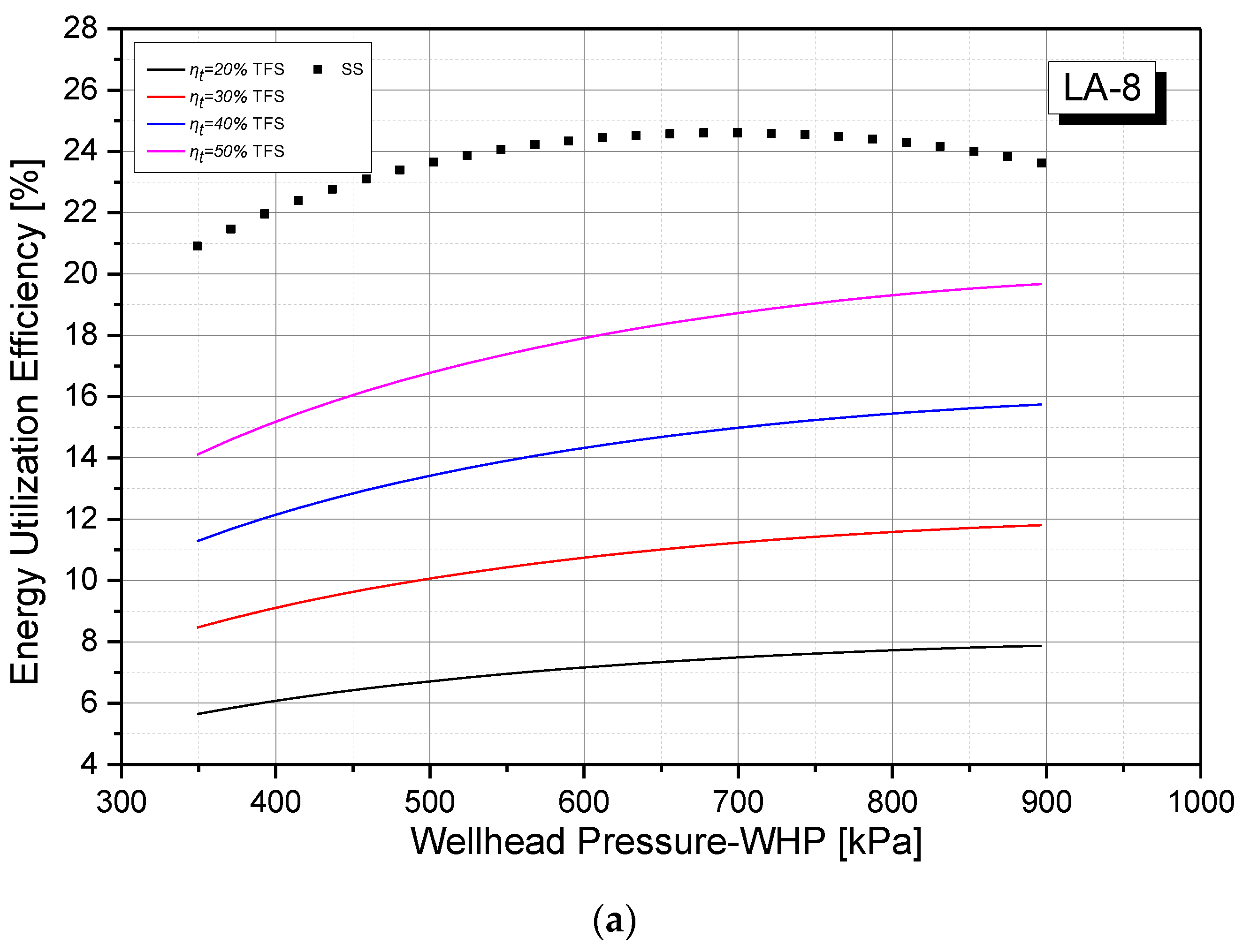
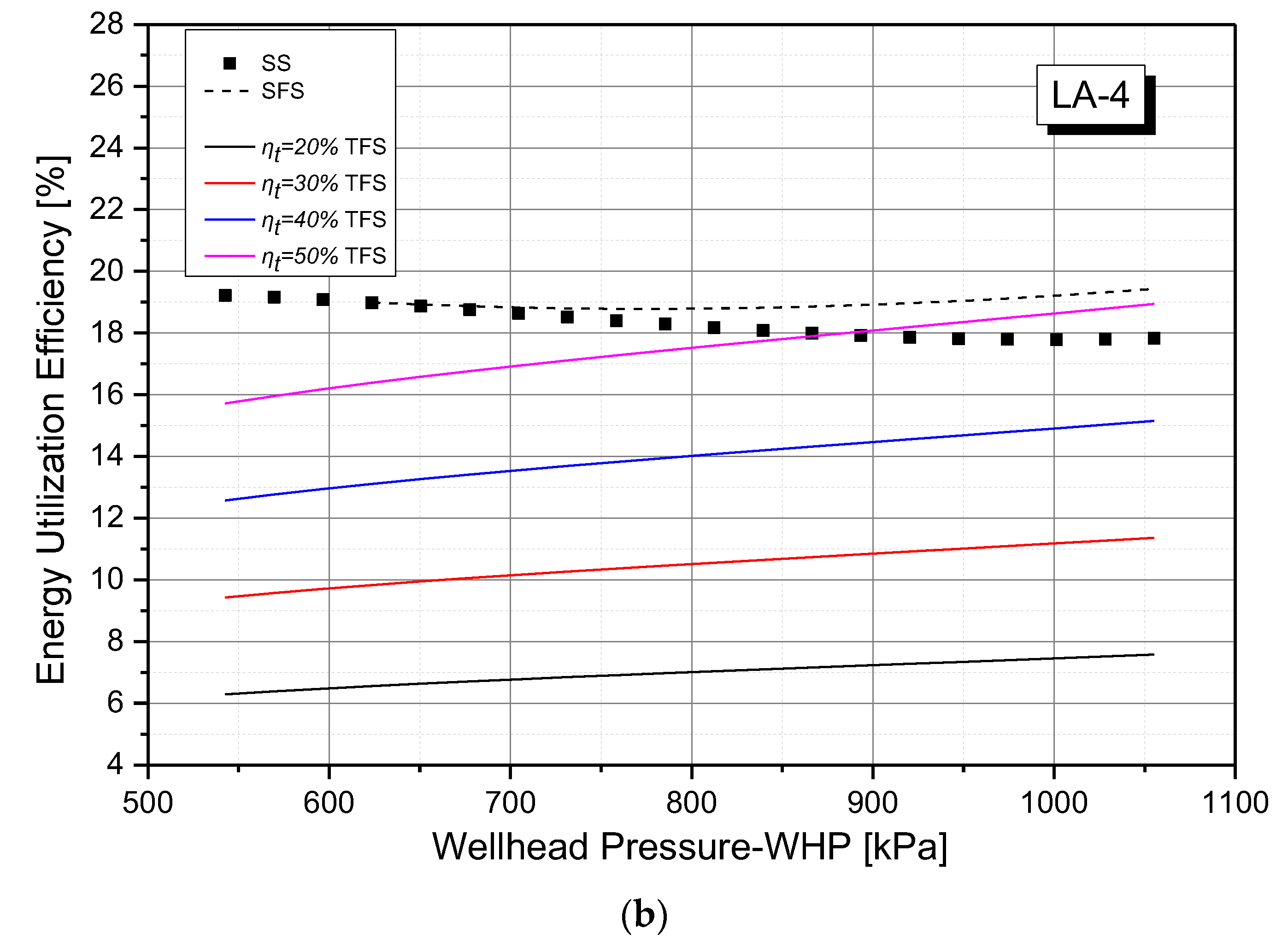
4.3. System Performance: Energy Utilization Efficiency
Comparing to that of LA-8, a higher exergy of total geothermal fluid is calculated under LA-4 conditions mainly because of its greater mass flow rate. Consequently, even though the power generation of LA-4 is higher than that of LA-8, the energy utilization efficiencies of trilateral flash system (TFS) are roughly in the same range under two well conditions. For instance, efficiencies of TFS are 14.1–19.7% of LA-8 and 15.7–18.9% of LA-4 if the total flow turbine efficiency is 50%.
However, the efficiencies of the traditional systems drop as the wellhead changes from LA-8 to LA-4. Comparison of
Figure 5a,b shows that the steam system and single-flash system have no big advantages over the trilateral flash system (TFS) regarding the energy efficiency when the total flow turbine efficiency is 50% under wellhead conditions of LA-4.
4.4. System Performance: Fresh Water Generation
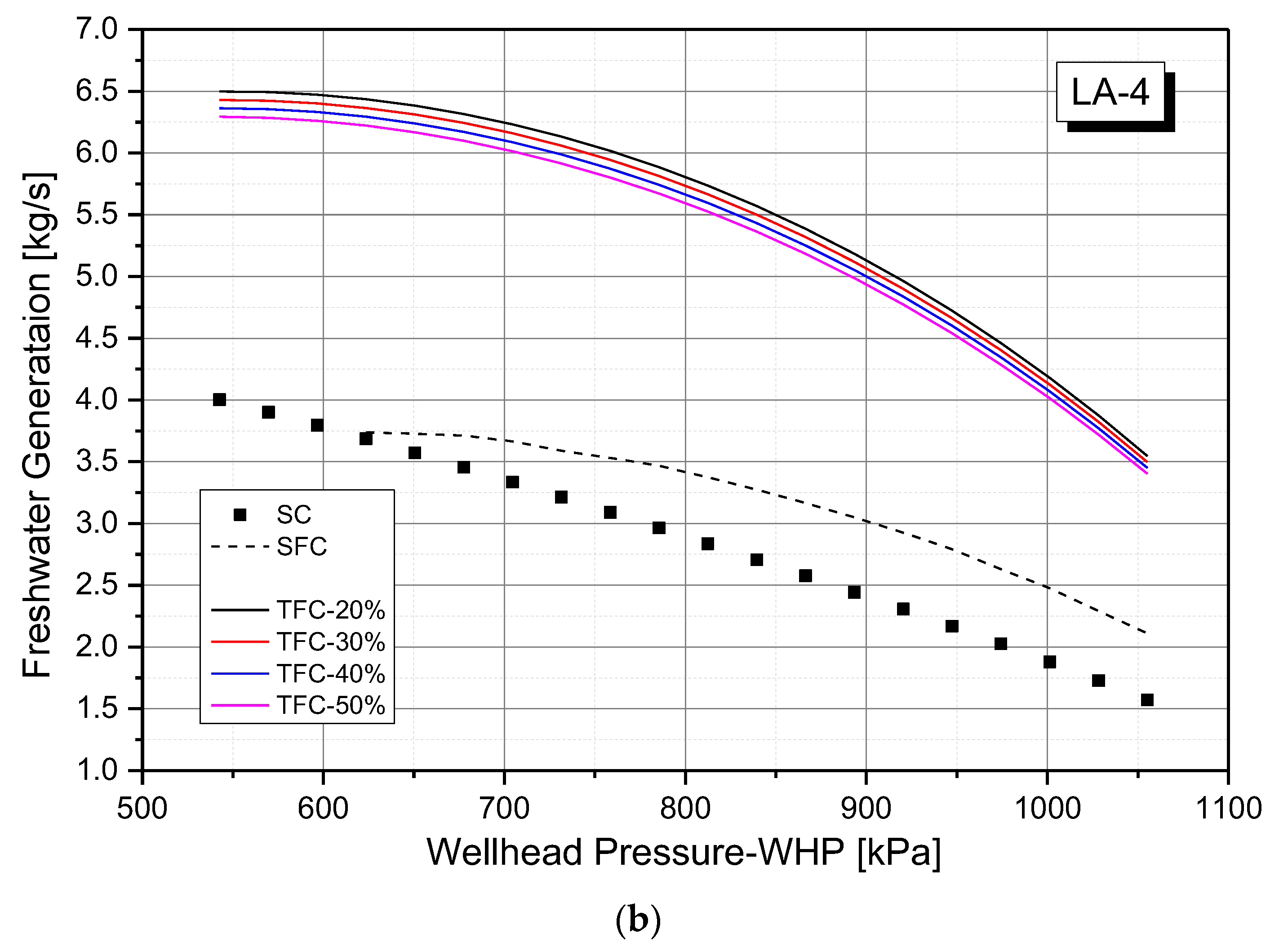
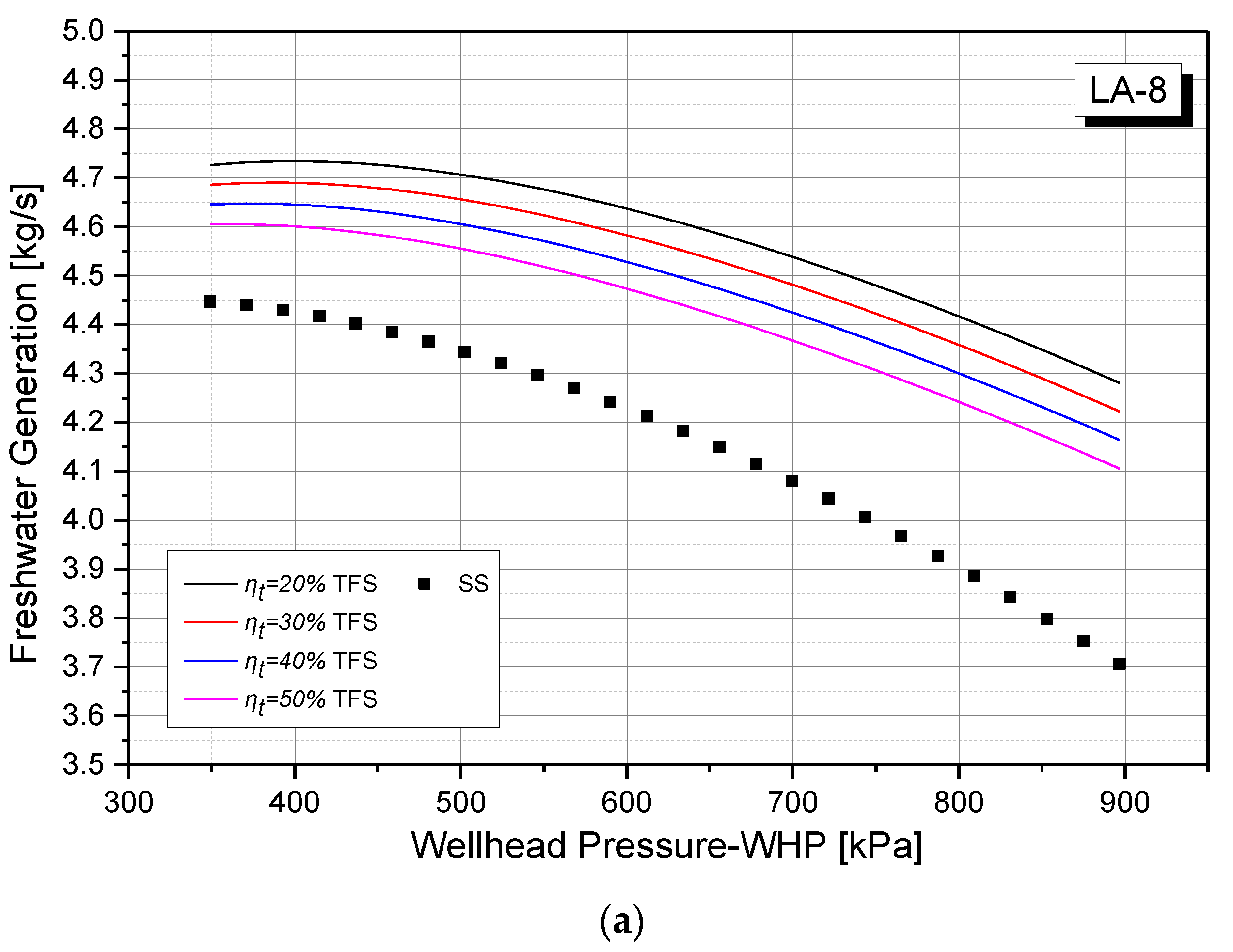
For a trilateral flash system (TFS), the advantage over traditional power systems is its fresh water generating capacity, as shown in
Figure 6. With a turbine efficiency of 20% the freshwater production of the trilateral flash system (TFS) can be up to 2.7 times higher than that of traditional systems. However, higher turbine efficiency leads to slighter lower specific freshwater production, because of lower turbine outlet vapor quality. The considerable amount of fresh water generated in the condensing stage is an extra benefit of the power system, especially for areas where there is a shortage of fresh water. The geothermal heat source is better utilized without adding separate water desalination systems. The three power systems have similar fresh water variations. The fresh water mass flow rates of three systems all decrease with the increase of wellhead pressure and the decrease of wellhead vapor quality.
Besides, comparison of
Figure 6a,b indicates that thermal systems under LA-4 conditions can reach a higher freshwater output amount than those with LA-8, and the advantage of freshwater generation of trilateral flash system (TFS) over traditional systems under LA-4 can be four times higher than that under LA-8 conditions. This is mainly dominated by the wellhead mass flow rate as well as vapor quality. For example, within the same wellhead pressure range from 550 kPa to 900 kPa, freshwater quantities of steam system (SS) are 3.7–4.3 kg/s and 2.4–4.0 kg/s under LA-8 and LA-4 conditions, respectively; the freshwater production rate of the single-flash system (SFS) is within the 3.0 to 3.7 kg/s range; freshwater generations of TFS with turbine efficiency of 20% are 4.1–4.5 kg/s and 5.2–6.5 kg/s under LA-8 and LA-4 conditions, respectively. On average, 31.4% and 23.6% of total wellhead flow is recoverable by the TFS system under LA-8 and LA-4 conditions, respectively.
4.5. Equivalent Energy Saving
More energy is saved by using condensation as freshwater generation without adding desalination equipment. In order to better estimate the energy benefits of the proposed power & freshwater generation concept, an equivalent energy saving index is introduced here. It should be noted that, as preset in the modeling, the condensation is designed to happen at atmospheric pressure to avoid vacuum and system complexity, the freshwater recovered has a near-boiling temperature of 100 °C, which qualifies them to be further utilized as hot freshwater and the extra energy saving and benefit can be obtained.
The up-to-date desalination technology survey reveals that 3 kWh/m
3 is consumed for freshwater generation which is equal to 10.8 kW/(kg/s) [
28]. By converting the freshwater generated from the thermal systems above to its equivalent energy savings, and adding them to the power generation, the equivalent energy saving of whole systems can be obtained, as listed in
Table 3.
As indicated in
Table 3, energy savings of freshwater generation can reach up to 70 kW under LA-4 conditions. The energy saving can be regarded as an extra benefit since the energy scale determines that adding a whole set of desalination subsystems would not be an economic solution for the particular field condition. By averaging the energy saving within the wellhead pressure range, the system equivalent energy savings under two wellhead conditions are listed. For LA-8 with higher wellhead vapor quality, the traditional steam system has an absolute energy saving advantage over the TFS. However, for more liquid-dominated wells like LA-4, the TFS would be comparable with traditional geothermal power systems regarding the total energy saving capacity.
5. Conclusions
To address the concurrent water and energy shortage issues in regions where geothermal sources are abundant, three combined power and freshwater generation configurations have been proposed and compared in this work, including a steam system (SS), a single-flash system (SFS), and a trilateral flash system (TFS). Both power-generating and water-producing performance was investigated, and conclusions are drawn as follows.
Regarding the power generation capacity, a total flow turbine with an efficiency of 50% makes the TFS comparable with SS and SFS under LA-4 conditions, but higher efficiency (ηtave > 50%) is needed for TFS in order to be competitive with the traditional systems for heat source like LA-8 with higher wellhead vapor quality.
Regarding the energy utilization efficiency, TFS with 50% turbine efficiency under LA-4 conditions has an efficiency range of 15.7 to 18.9%, and steam system and single-flash system have no major advantages over it.
The biggest advantage of the TFS over traditional power systems is its fresh water generating capacity. With a turbine efficiency of 20%, the freshwater production of TFS can reach up to be 2.7 times higher than that of traditional systems. On average, one-quarter to one-third of wellhead flow is recoverable by the system.
The TFS is comparable with traditional geothermal power systems regarding the total energy saving capacity. Its average value of equivalent energy saving within the LA-4 wellhead pressure range is 728.7 kW when turbine efficiency reaches 50%.
Generally speaking, a trilateral flash system (TFS) with suitable turbine efficiency can be comparable with the widely-used traditional steam system (SS) and single-flash system (SFS) regarding the power generation. Moreover, as a distinct advantage of the TFS, the freshwater generation capacity qualifies the TFS as a promising choice in remote arid geothermal terrains with both power and freshwater needs.


