Article

Visual Experimental Study on Gradation Optimization of Two-Stage Gravel Packing Operation in Unconventional Reservoirs

1
Petroleum Engineering, China University of Petroleum (East China), Qingdao 266000, China
2
Petroleum Systems Engineering, Faculty of Engineering and Applied Science, University of Regina, Regina, SK S4S 0A2, Canada
3
PetroChina Huabei Oilfield Company, Cangzhong 062552, China
*
Author to whom correspondence should be addressed.
Energies 2019, 12(8), 1519; https://doi.org/10.3390/en12081519
Submission received: 2 April 2019 / Revised: 16 April 2019 / Accepted: 18 April 2019 / Published: 22 April 2019
(This article belongs to the Special Issue Development of Unconventional Reservoirs)

Abstract

:
During the development of unconventional reservoirs with high sand production rate and fine silt content such as heavy oil and hydrate reservoirs, silt sand blockage problem is a serious issue. A two-stage gravel-packing sand control technique is applied to solve the silt sand blockage now. However, traditional experiments on this technique could not obtain the dynamic distribution law of intrusive sand in the gravel pack. In this study, a new visualization experiment based on hydrodynamic similarity criterion for studying particle blockage in gravel packs was conducted. Real-time monitoring of sand particle migration in the gravel pack could be achieved. Also, the stable penetration depth and the distributing disciplinarian of invaded particles could be determined. The results show that when the gravel-to-sand median size ratio of gravel bed I is less than five, the sand bridge can be formed at the front end of the gravel pack. This could prevent sand from further intruding. As the grain size of gravel bed II is increased, the flow velocity is reduced. Thus, the sand invading into gravel bed II tends to settle at the interface. A large amount of sand intrusion can happen to gravel pack II when the pore filling front breaks through the gravel bed I.

1. Introduction

Sand production has become one of the main factors restricting the efficient development of unconventional reservoirs such as hydrate and heavy oil reservoirs. It is mainly reflected in the damage to the near region of the wellbore, artificial lift, and surface equipment. A high-rate gravel-packing sand control technique has been widely applied to solve this problem. This technique has high sand control efficiency, a long validity period, and alleviation of the productivity impairment caused by the sand blocking material [1,2,3]. However, after a period of production, the gravel pack could be blocked by silty sand. Sparlin studied the permeability of common size gravel with different percentages of silty sand [4]. The study showed that the permeability of the gravel would be seriously decreased after mixing a small amount of silty sand. When the gravel pack blockage occurred in tubing-casing annulus and perforation holes, the additional pressure in the gravel layer could be raised significantly. Thus, well productivity would be decreased, and unnecessary reservoir energy loss would occur.
For unconventional reservoirs with high sand production rate and fine silt content, it is necessary to adopt appropriate sand control technology to achieve effective exploitation [5]. Two-stage gravel packing sand control technology is one of the most mature appropriate sand control technologies. This technology can effectively solve the sand blockage problem in high argillaceous and silty sand reservoirs. Gravel bed I with smaller grain size is packed to prevent the invasion of particles of larger grain size. The bigger grain size of gravel bed II allows the silt particles transported to gravel bed II to be discharged with the produced fluid. This can effectively avoid the blockage, and the permeability could be impaired, as shown in Figure 1. Good application efficiency was achieved [6,7]. The advantage of this sand-control technique is that it can effectively alleviate the blockage of the gravel layer and increase the effective period of the gravel pack.
The main causes of permeability damage of a gravel pack are particle migration, deposition, and blockage in gravel pores. Clarifying the plugging mechanism of a gravel pack is of great significance when optimizing sand control design. Also, it can help to predict the productivity of sand control wells more accurately. Due to the heterogeneity of pore throat and particle size distribution in the gravel pack, it is difficult to describe the clogging process accurately by analytical and theoretical methods only. It is necessary to conduct physical simulation research and revise the theoretical model based on the experimental results of studying particle transport in porous media. Many scholars have conducted a series of studies on particle migration in porous media and obtained many useful results. Bouhroum and Civan studied the pore structural changes of the gravel pack due to the clogging process of intruding particles by visualizing laboratory investigation. They concluded that the particulates migration process is characterized by a discontinuity of particulates concentration [8]. Bigno et al. studied the trends of gravel pack permeability reduction as a function of pore blocking and identified five prevailing pore blocking mechanisms [9]. To estimate the amount of deposited material quantitatively, Ail et al. used an on-line linear X-ray apparatus to study the deposition profile in deep bed filtration during produced water re-injection [10]. Deep penetration can be distinguished from external filter cake buildup by this method. Shirinabadi et al. studied the effect of gravel pack size on sand production experimentally and numerically [11]. Villarroel et al. built a gravel pack prototype of the two most common mesh sizes (16/20 and 20/40) and tested the influence of the gravel size under high in-situ stress contrast [12]. Lawal et al. carried out a series of studies on porous media permeability impairment by incorporating the kinetics of dynamical particle deposition into the classic deep-bed-filtration theory [13]. Gravelle et al. reproduced particle generation and particle transport in porous media and detachment after ionic strength reduction by laboratory experiments [14]. Li et al. studied the blockage rule of particles in a gravel pack experimentally and established the damage evaluation model of physical parameters of the gravel filling layer using the deposition model of particles in the liquid phase [15,16]. In addition to the above, many other scholars have characterized the deposition and plugging mechanism of particles in porous media through laboratory experiments and theoretical study [17,18,19,20,21,22,23,24].
Traditional experimental studies of gravel packs are usually conducted in invisible metal sand-filling pipes. The results typically obtained from the experiments convey little pressure distribution along the pipes [25,26,27]. The sand front interface and the penetration depth in a gravel pack cannot be obtained from the experiments. Also, simulation studies with a one-dimensional phenomenological model based on the average particle concentration obtained by experiments have been conducted [28,29,30,31,32]. However, these simulation studies cannot characterize the particle distribution. These studies cannot provide an effective guidance for gravel packing design. To meet the need of the two-stage gravel packing design, visualization experiments need to be conducted to determine the penetration depth of intrusive particles in a gravel pack. In this paper, newly designed visualization experiments were conducted to study the dynamic distribution of intrusive particles in the two-stage gravel pack. The influence of the two-stage gravel size and the packing ratio was analyzed based on our experimental results. The design optimizations of the two-stage gravel packing process are described herein.

2. Experimental Design
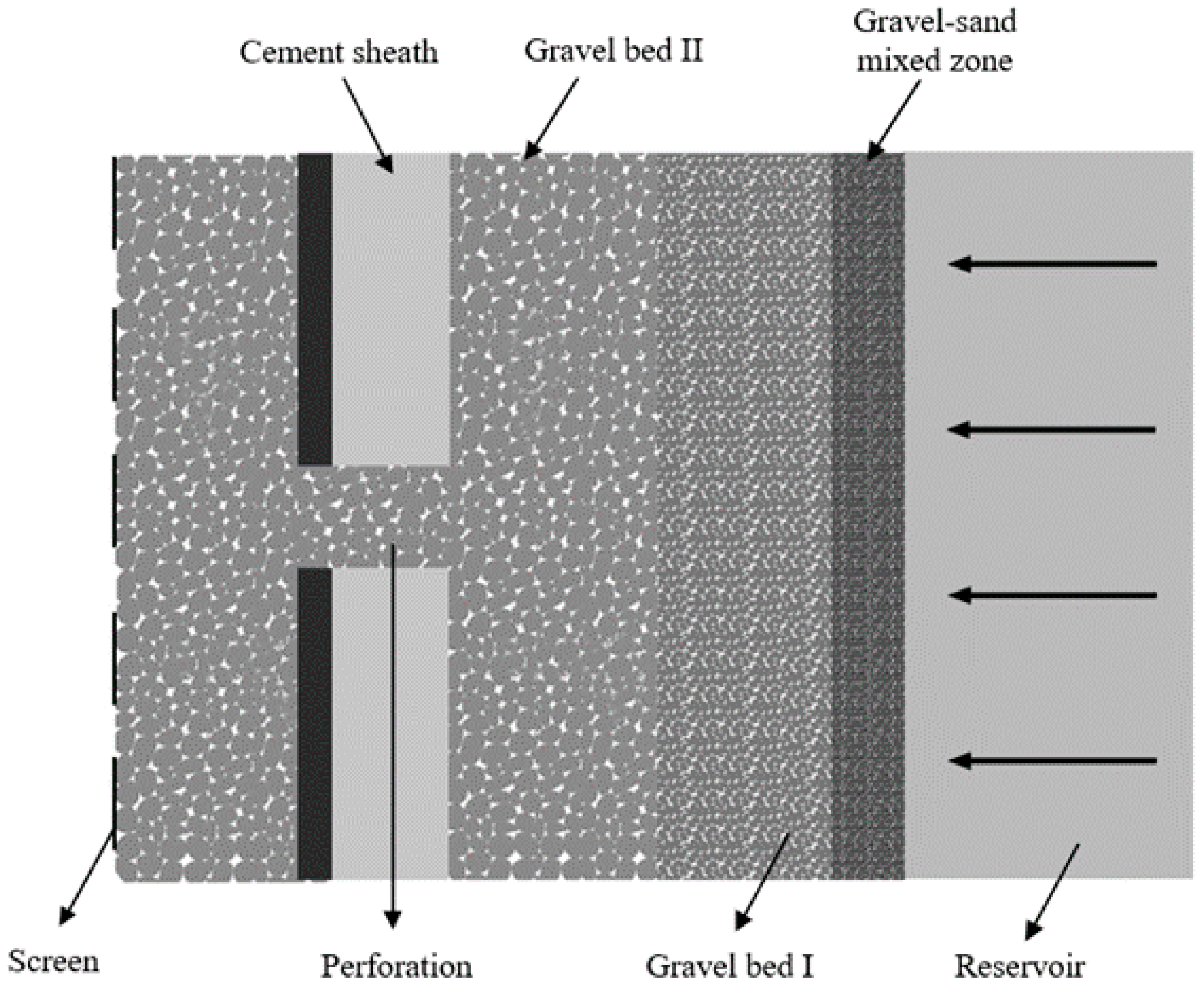
2.1. Methodology

There is no chromatic aberration between the packed gravel and the sand. Thus, the visualization cannot be achieved. Moreover, it is difficult to separate sand from gravel after the experiment, and the measurement of retained particles is hard to carry out. In this experiment, the prototype was enlarged. Glass beads were used instead of gravel to meet the experimental requirements of visibility and measurability. In the process of hydrodynamic and solid-liquid two-phase flow experiments, it was necessary to ensure a certain flow similarity between the model and the prototype. This required a fixed proportional relationship of physical quantities (geometrical, kinematical, and dynamical). To fit the motion modes of the sand particle in an actual stratum, similarity criteria needed to be established to determine the similarity scale of time, velocity, and flow in the visualization model. For the solid-liquid two-phase flow, flow and particle Reynolds criterion, Stokes criterion, and Freud criterion were the four dominant similarity criteria in designing the experiments.
l p ρ p u p μ f p = l m ρ m u m μ f m   ( R e ) p = ( R e ) m
d s p ρ s p u r p μ f p = d s m ρ s m u r m μ f m   ( R e s ) p = ( R e s ) m
d s p 2 ρ s p u r p μ f p l p = d s m 2 ρ s m u r m μ f m l m   ( S t k ) p = ( S t k ) m
ρ p l p 2 u p 2 ρ p g l p 3 = ρ m l m 2 u m 2 ρ m g l m 3   ( F r ) p = ( F r ) m
where subscript p represents prototype and subscript m represents model; Re and Res are the flow and particle Reynolds number, dimensionless; Stk is the Stokes number, dimensionless; Fr is the particle Freud number, dimensionless; l is the geometric characteristic length, m; ds is the particle diameter, m; ρ and ρs are the fluid and particle density, kg/m3; u and ur are the fluid velocity and relative velocity between solid and liquid phases, m/s; μ is the fluid viscosity, N·s/m2.
In the experiment, the prototype and the model could not satisfy all the above similarity criteria at the same time [33,34]. The approximation model was adapted to ignore the secondary factors. By ignoring the difference of surface roughness between gravel and glass beads, the fluids and the particles used in the experiment could be regarded as the same as those in natural conditions. When the Reynolds number of the prototype and the model was in the same self-modeling region, the similarity with criterion number Re could be ignored. For the flow in the sand-packing tube, the vertical distance that the gravity acted on was relatively short, thus the Froude number (Fr) that reflected the gravity action could be ignored. After the above simplification, it was concluded that the prototype and the model should have obeyed the particle Reynolds and Stokes similarity criteria for designing the experiment.
The following scale relations were obtained according to the established modeling law:
λ v = λ l 1 λ t = λ l λ v = λ l 2
where λl is the length similarity coefficient equal to lp/lm; λv is the velocity similarity coefficient equal to up/um; λt is the time similarity coefficient equal to tp/tm.
According to the selected similarity criterion, the velocity magnification of the experiment was determined to be equal to the λl. For example, if the quartz sand with ten times enlarged median grain size was selected to simulate the intrusive sand in the real situation, the injection rate of the visual experiment should be set as ten times the traditional displacement experiments.

2.2. Experiment Materials

The experimental set-up is shown in Figure 2. The Kamoer Lab UIP-S25-6 peristaltic pump was selected as the displacement pump with a range of 1–1300 mL/min. The liquid injection caliber was 8 mm, and the sand production was measured by the container placed at the outlet of the pipe. To achieve the visualization of sand migration and blockage in the gravel bed, a clear cylindrical PMMA (poly methyl methacrylate) pipe with a diameter of 40 mm and a length of 300 mm was selected as the sand-packing tube. The gravel used in traditional experiments were replaced by scale-up glass beads to monitor particle transportation. The injection rate was determined according to the hydrodynamic similarity criterion discussed before, thus, the motion of sand particles in the simulation bed was similar to the real situation. During the experiment, the movement and the blockage of particles in the gravel layer were monitored by real-time photography. When the gravel-sand interface was stable, the glass beads and the retained sand were taken out and weighed separately. Thus, the plugging degree of each section could be obtained.
According to the selected similarity criterion, the geometric magnification of the experiment was determined to be ten times. Taking sand with 0.1 mm median grain size as an example, the quartz sand with ten times enlarged median grain size was selected to simulate the intrusive sand in a real reservoir. The glass beads with specific particle size were selected to simulate gravel packs to ensure the visibility and measurability of intrusive particles. During the experiment, the temperature was kept at 20 degrees and the pressure was 1 atm. The injection fluid was the glycerol mixture with the viscosity of 5 cP.

2.3. Experiment Procedure

A schematic of the experiment is illustrated with Figure 2. The general procedure of the experiment is described as follows:
(1)
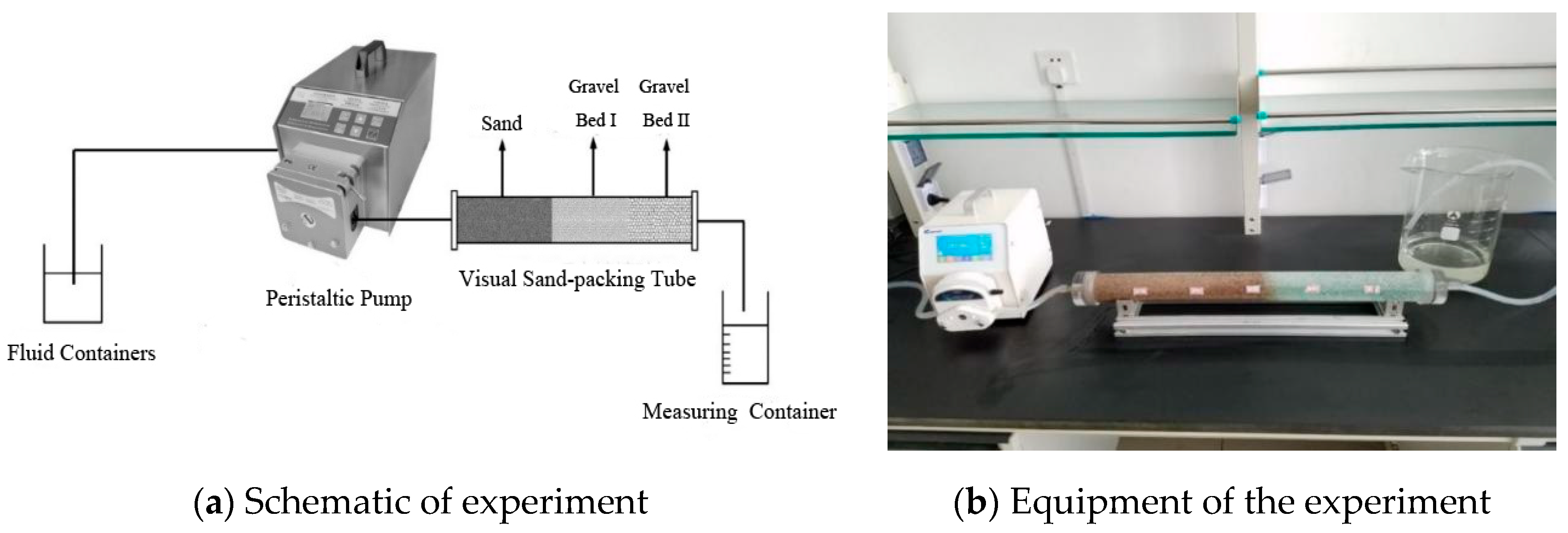
Clean up the tube and place the metal gauze at the outlet joint to prevent the glass beads from discharging at the outlet. This can help to ensure the flow stability during the experiment.
(2)
The end of the tube is sealed, and the composite simulated quartz sand sample is filled to one side. After packing to the design depth, the sand sample is compacted. Then, pack glass beads into the pipe from the other end and compact slightly. During packing, the quartz sand should be kept at the bottom to prevent a large amount of pre-intruding sand before the experiment.
(3)
After calibrating the flow rate of the peristaltic pump, the displacement container, the peristaltic pump, and the sand-packing tube are connected. The depth of sand invasion, the movement of the gravel-sand interface, and the sand distribution characteristics are recorded every 10 min during the experiment.
(4)
After displacement, unfold the sand-packing tube from the exit end. The glass beads and the retained sand are extracted from segments. The mixture is filtered, and the glass beads and the retained sand are recovered separately. The amount of retained sand of this packing section can be obtained by weighing the dried recycled sand.

2.4. Experiment Scheme

In order to investigate the influence of the two-stage gravel size and packing length on the two-stage gravel bed, the experimental scheme was designed as shown in Table 1.
The experimental design adopted in this work was based on the principle of moderate sand control. Moderate sand control should raise the sand retention rate of gravel bed I to avoid the blockage of gravel bed II. The design of gravel bed I grain size was based on the criterion proposed by Saucier. After taking both conductivity and sand retention rate into account, Saucier proposed that the gravel-sand size ratio should be 5–6 [35]. The selection of gravel bed II grain size was mainly based on field experience and the commonly used size of industrial gravel derived from the operation of two-stage gravel packing in Shengli Oilfield, China [7]. The design of the injection rate was based on the experimental data of Li et al. in the conventional gravel packing displacement experiments [15,16].

3. Results and Discussions

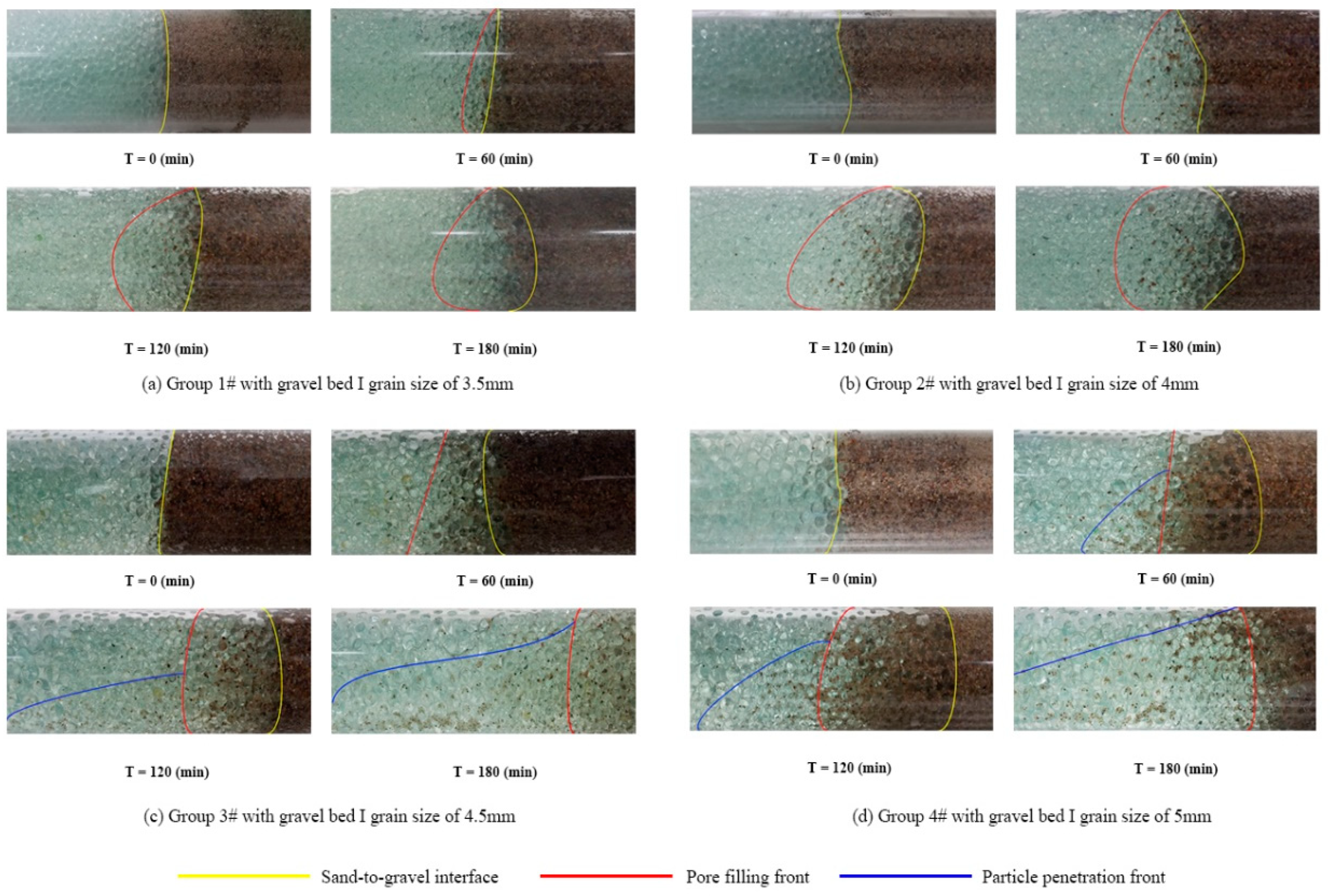
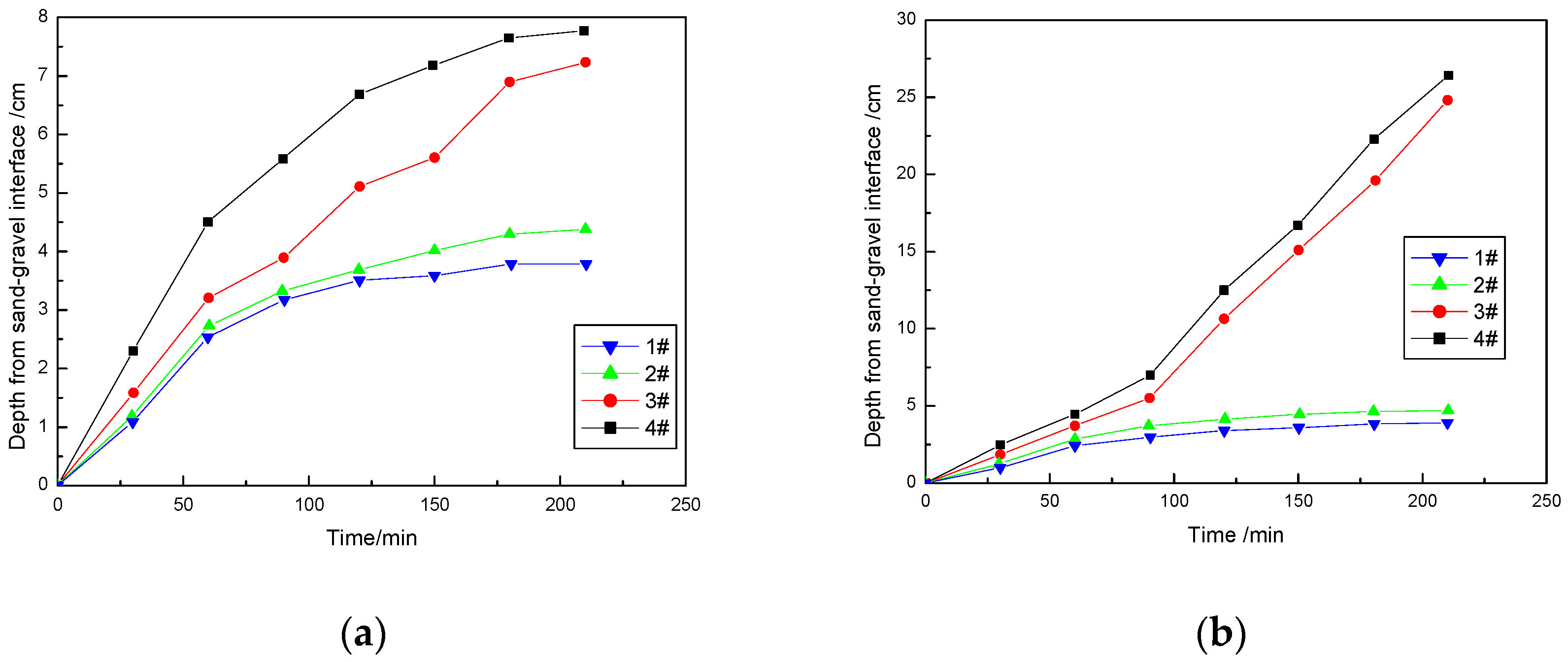
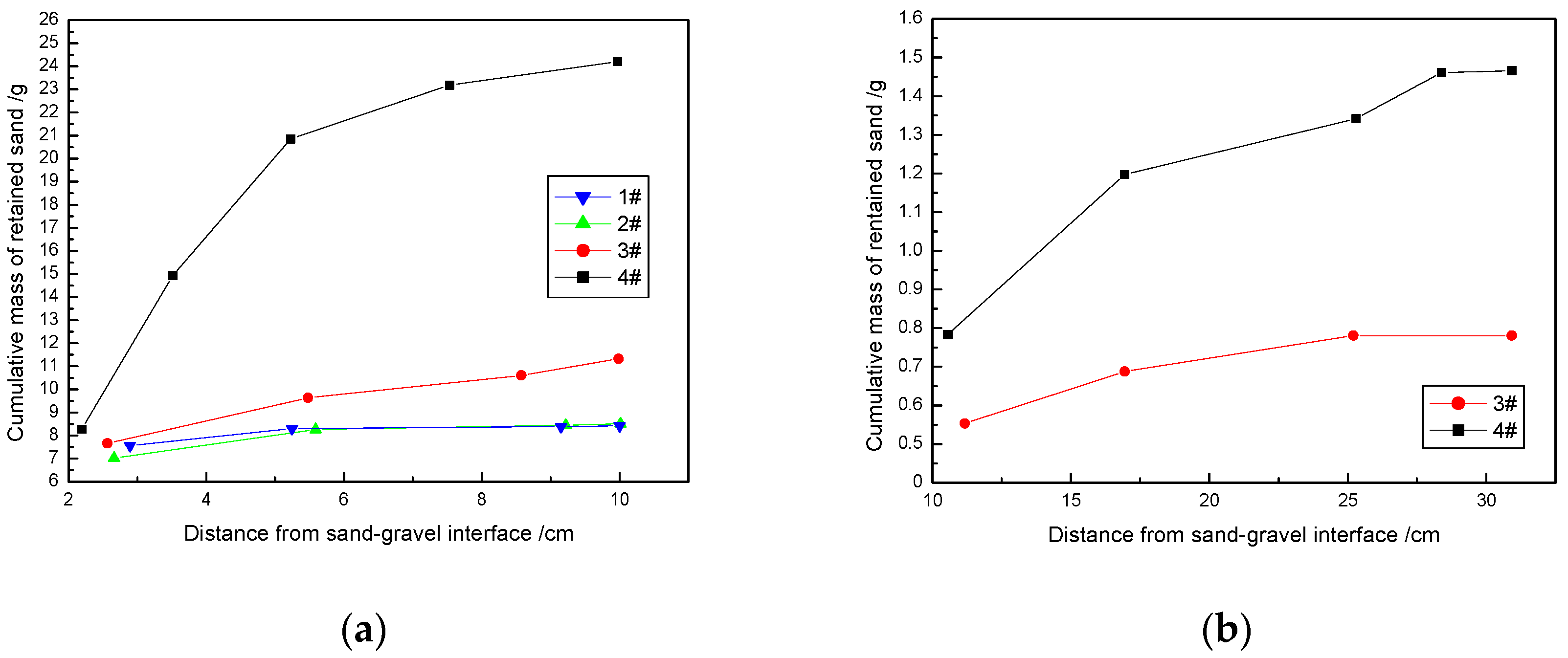
3.1. Particle Grain Size of Gravel Bed I

The grain size of packing gravel in gravel bed I is one of the most critical factors impacting the permeability of the two-stage gravel packs. Currently, the selection criteria for gravel grain size of field operation mainly refer to the research of Saucier, which suggested a five to six times gravel-size median grain size ratio. By our visual experimental study, the sand penetration depth of four groups of different gravel-sand grain size ratio was obtained. This could provide an accurate and quantitative basis for the design of two-stage packing proportion. The experimental scheme is illustrated with groups 1#–4#, Table 1.
In the four groups of experiments, the sand-to-gravel grain size ratio of gravel bed I was conformed to the design criterion of field operation. By conducting the visual experiments, the penetration depth and the distribution characteristics of the intruding particles of different gravel size was obtained. Thus, it could help to design the packing gravel grain size and the effective packing depth of gravel bed I. It could effectively prevent deep intrusion of sand into gravel bed II. Also, in this way, overall gravel pack permeability could be maintained or increased. During the experiment, the dynamic settlement and the blockage of intrusive sand in the pore space of the gravel were observed and regularly recorded, as shown in Figure 3.
The sand-gravel interface, the pore filling front, and the sand penetration front are shown in Figure 3. The pore filling zone refers to the gravel-sand mixing area where the pore throat was blocked severely at the gravel-sand interface due to the massive invasion of the sand particle. The sand penetration front indicates the longest distance of intrusive sand migrated into the gravel pack. It can be seen that the grain size of grade I gravel had an obvious influence on sand migration and blockage in formation.
The influence of gravel bed I grain size on sand migration and blockage in the gravel pack was obviously observed during the experiment. When gravel grain size was 3.5–4 mm, gravel bed I had a better sand controlled efficiency compared with other groups. This resulted in the shorter sand filling length, the slower expansion speed, and the lower level of the gravel pack plugging the degree near the sand-gravel interface. Also, a stable sand bridge could be formed in the pore space of the packed gravel. A stable sand bridge could restrain the expansion of the particle penetration front. The amount of retained particles of the gravel pack could be increased substantially with the enlargement of packed grain size. With the increase of pore space, it took a longer time to form a sand bridge that could exclude further particle intrusive. Thus, the penetration depth of particles was increased obviously.
It can be seen from Figure 4a that when the gravel grain size was less than five times that of the median grain size of the formation sand (group 1# and group 2#), the gravel bed I entirely excluded the further intrusion of the production sand. The variation characteristics of pore filling depth were similar in groups 1# and 2#. Both of them had a stable pore filling depth of 3–4 cm, which was nearly two times smaller than that of groups 3# and 4#. When the gravel-to-sand grain size ratio was more than five according to the Saucier criterion (group 3#), the depth of the gravel-sand mixing zone was increased significantly. However, when the grain size continued to increase to 5 mm, there was no obvious change in the trend of the pore filling front. The stable filling depth was slightly increased from 7 to 7.5 cm.
The particle penetration front of the gravel pack could be divided into two groups based on whether it was five times larger than the median grain size of the intruding sand, as shown in Figure 4b. In groups 1# and 2# with gravel bed I grain sizes of 3.5 mm and 4 mm (gravel-sand size ratio less than five), a stable sand bridge existed that could prevent the particles from further intrusion into the gravel-sand mixing zone. With the increase of packing gravel size, a large number of intrusive sands migrated to the deep place. Both of the experiments for group 1# and group 2# had a particle penetration depth of up to 20 cm. Additionally, because the overall blockage in the gravel pack was not critical, this part of the sand could usually be settled in the lower part of the pipe wall due to the action of gravity, as shown in Figure 3.
Figure 5 shows the distribution of sand retention in the two-stage gravel beds. The sand retention of the two groups of experiments with smaller grain size could only be detected in gravel bed I, which was mainly concentrated at 3–4 cm, where the pore fill took place. The mass of retained sand all over the gravel beds of groups 1# and 2# was about 7.8 g, which was much less than the other two groups. The amount of sand retained in the first 3 cm of the experimental group with gravel grain of 4.5 mm was similar to that in the experimental group with 3.5 mm and 4 mm diameters. However, it covered deeper gravel bed in longitudinal depth since there was retained sand detected in the gravel pore with a distance of 27 cm from the interface. Although the pore filling and the penetration depth of the two experimental groups with particle sizes of 4.5 mm and 5 mm were similar, the overall blockage amount of the gravel pack was much larger because of the larger pore inlet area and the accumulation space. The mass of retained sand all over the two gravel beds in group 4# was 26 g, which was much larger than that in group 3#.
By analyzing the obtained experimental results, it can be concluded that when the gravel-sand grain size ratio was less than five, sand bridges that formed in the pore space of the gravel pack could restrain further penetration of particles intrusion. The depth of the gravel-sand mixing zone was decreased, and there were few particles entering gravel bed II. Therefore, the gravel-sand grain ratio of gravel bed I could be controlled within five. At the same time, the packing length of gravel bed I should have been reduced, and the packing grain size of gravel bed II should have been increased to improve the gravel pack’s overall permeability.

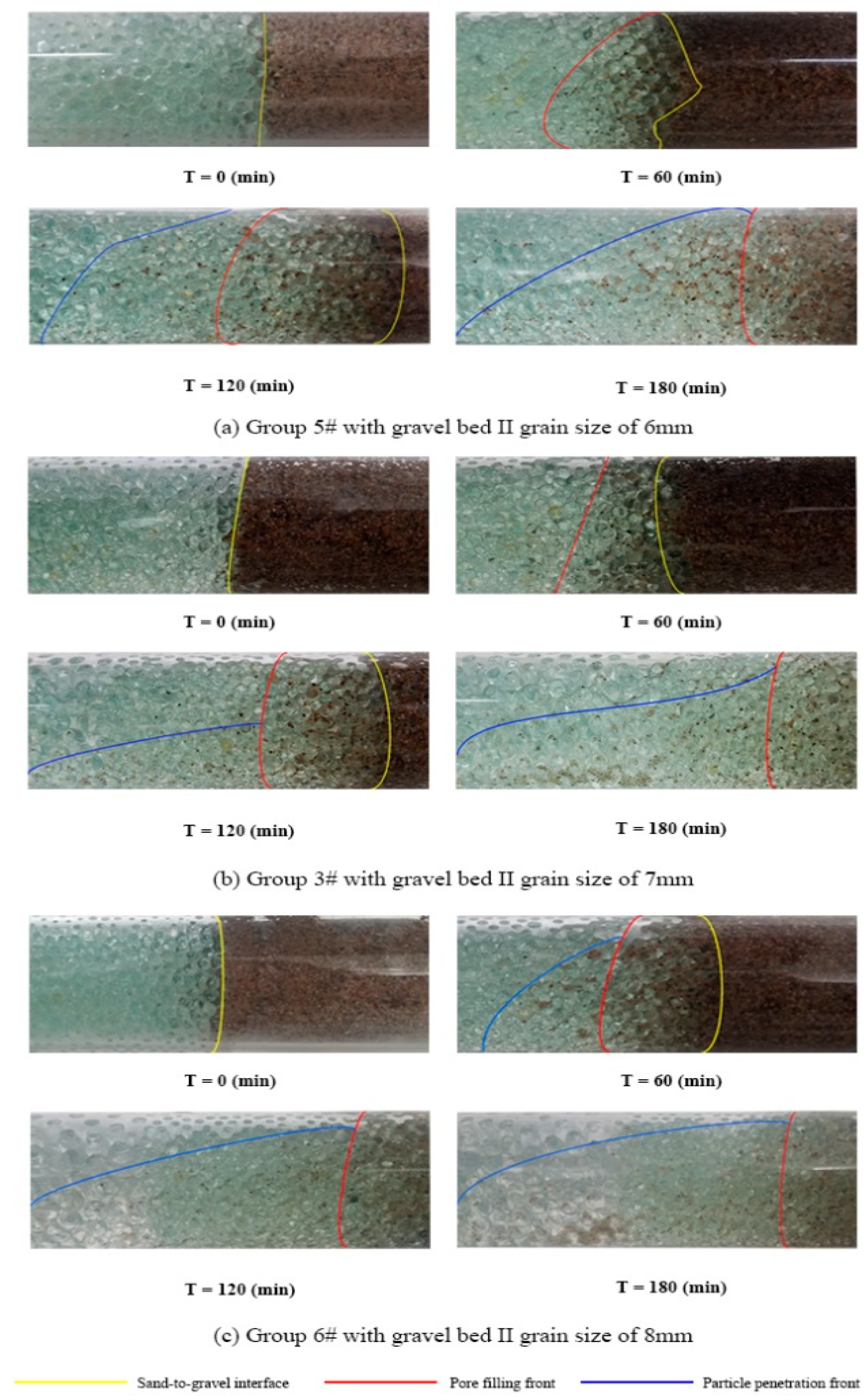
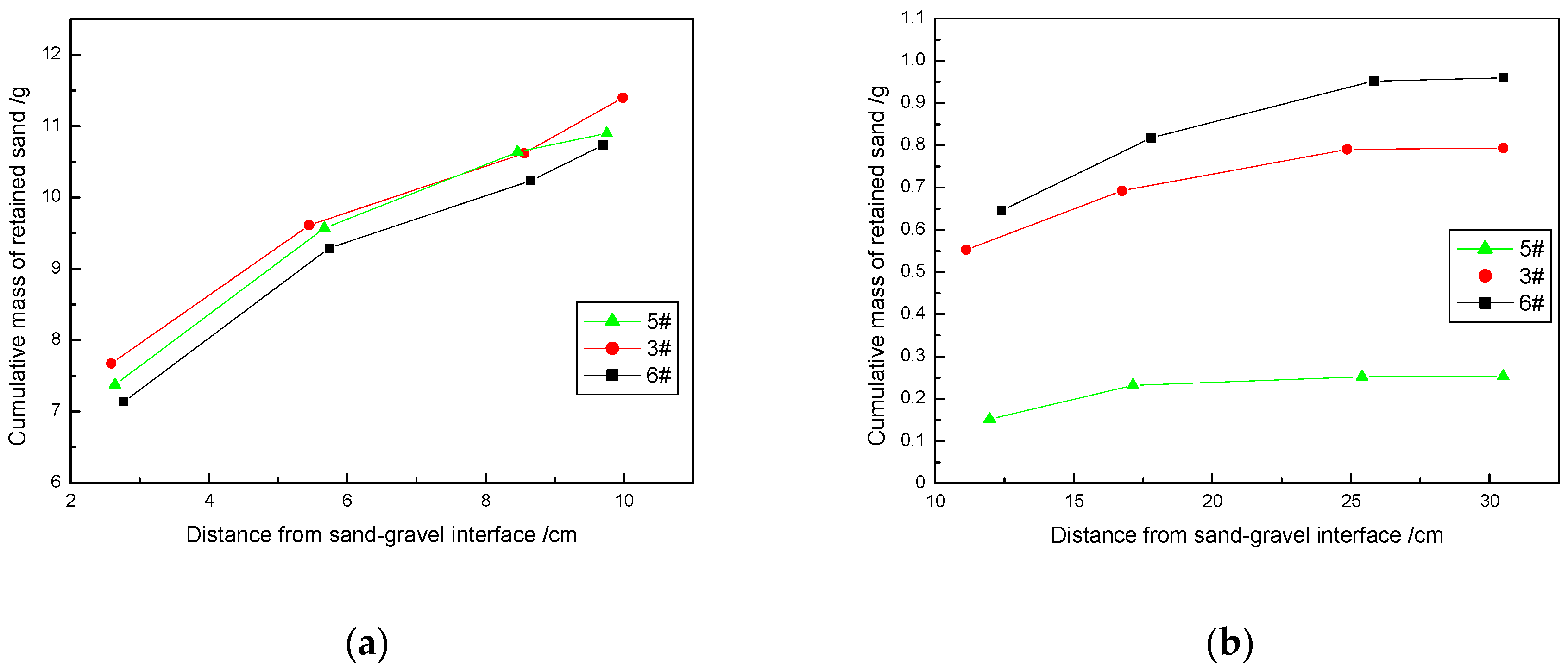
3.2. Particle Grain Size of Gravel Bed II

Until now, there had been no reliable criterion for packing gravel selection of gravel bed II. To increase the validity period and the permeability of the gravel pack, the following principles should be followed in designing packing gravel in gravel pack II. Packed gravel should effectively prevent the gravel in bed I from further migration.
In the three experimental groups, the median grain size ratio of gravel bed II to gravel bed I ranged from 1.33 to 1.78, which covered the possible combination range of industrial gravel selection of the field operation. The dynamic blockage in the gravel pack of the experiment is shown in Figure 6. The pore filling front of the three groups had similar regularity, while the penetration depth was quite different. With the increase in packing grain size of gravel bed II, the gravel pack’s pore space was increased, and the fluid velocity in the pore of the gravel layer was decreased. This resulted in a significant increase in the sedimentation sand at the interface between gravel beds I and II.
It can be seen from Figure 7 that these three groups had similar change regulation. Also, the steady-state values of the pore filling depth were all about 7 cm. The grain size of gravel bed II mainly affected the dynamic development law of the particle penetration depth. During the first 90 min of the experiment, the intrusive particles mainly migrated in gravel bed I, thus the three groups’ penetration depths had similar development characteristics. As the frontier of penetrated sand migrated to the junction of gravel beds I and II, the increase in gravel size led to more sand intrusion. Meanwhile, because the fluid flow velocity in the pore throat became slower, the experimental group of the larger gravel bed II gravel had more sand settlement at the two-stage gravel pack interface. Compared with group 5# with gravel grain size of 6 mm, the penetration depth of group 3# with grain size of 7 mm was increased significantly by 8 cm. Meanwhile, when the grain size was changed from 7 mm to 8 mm in group 6#, the penetration depth was only changed by 2 cm.
In group 5# with a gravel bed II grain size of 6 mm, the channel for blocked sand migration at the interface was relatively small, thus it was more difficult for particles to further enter gravel bed II, and this reduced the amount of retained particles, as shown in Figure 8.
When the grain size of gravel bed II was increased to 7 mm, the amount of sand retained at the interface was increased by 0.4 g compared with the group of 6 mm. The reason is that the amount of sand intruded was increased by the increase of the pore throat and the particle settlement caused by the decrease of flow velocity at the interface. However, the sand deposited at the interface did not further migrate, thus no blockage occurred to gravel bed II. The experimental group of packing grain size with 8 mm had a similar regularity in retained sand distribution law as the group with 7 mm, with only a minor increase of 0.2 g.
The following conclusions can be drawn from the above study: the grain size of gravel bed II had little effect on the length of the pore filling zone and the amount of retained particles of gravel beds I and II. It mainly affected the amount of retained sand at the two-stage interface and the particle penetration depth. During the experiment, the amount of retained sand at the interface of the experimental group with a grain size of 7 mm was larger than that of the experimental group with 6 mm, but it was a bit smaller than that of the experimental group with a grain size of 8 mm. From the perspective of maximizing overall permeability, 8 mm should be selected as the grain size of packed gravel in gravel bed II.

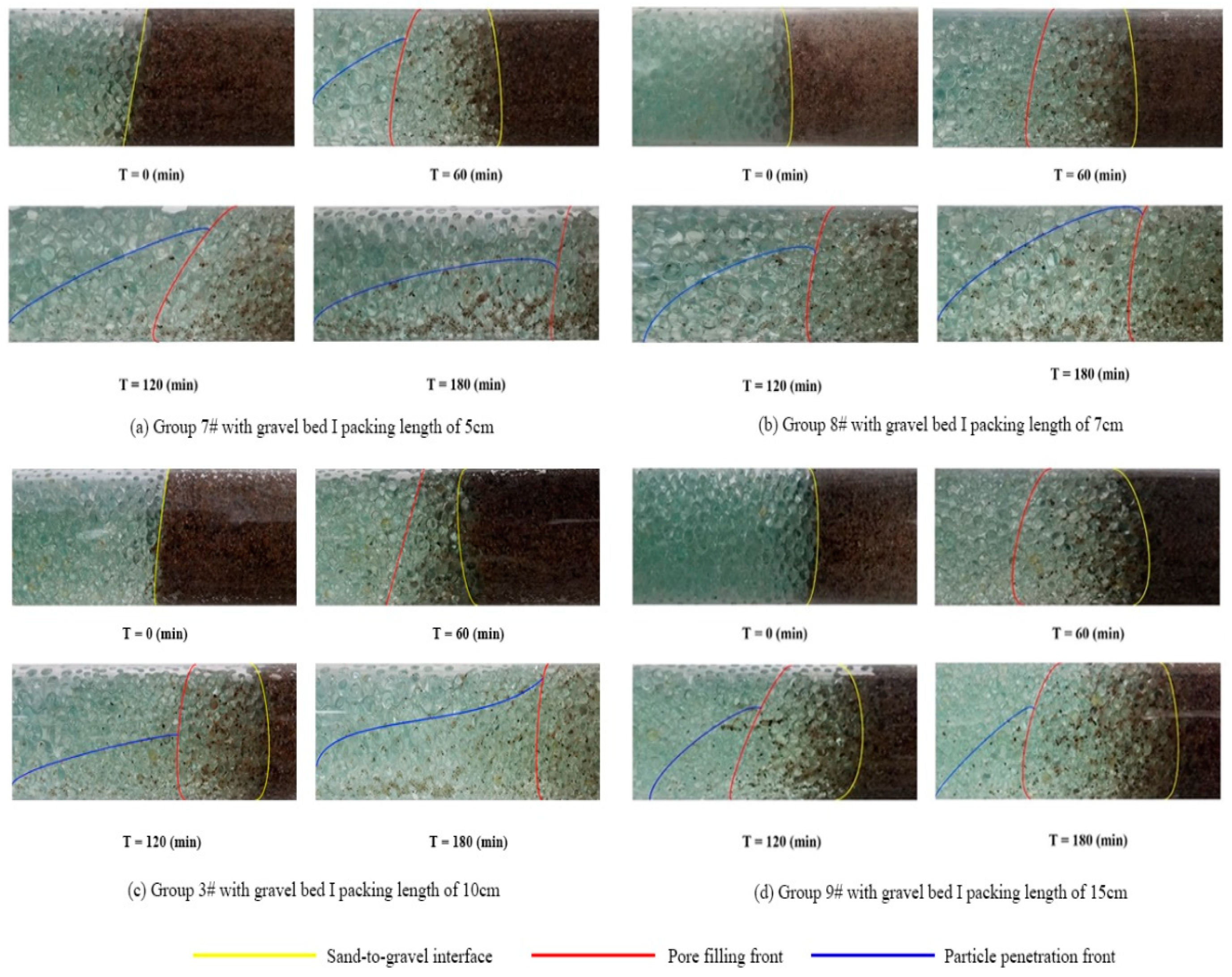
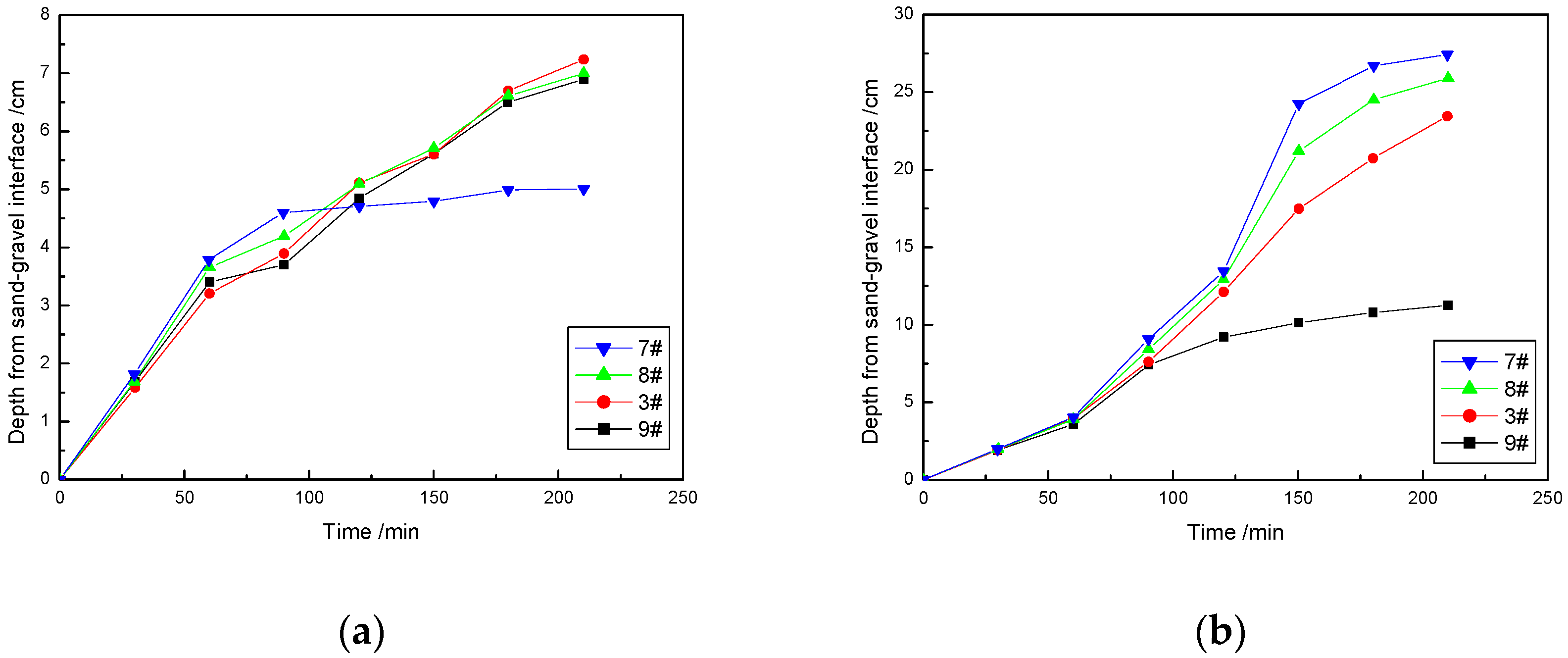
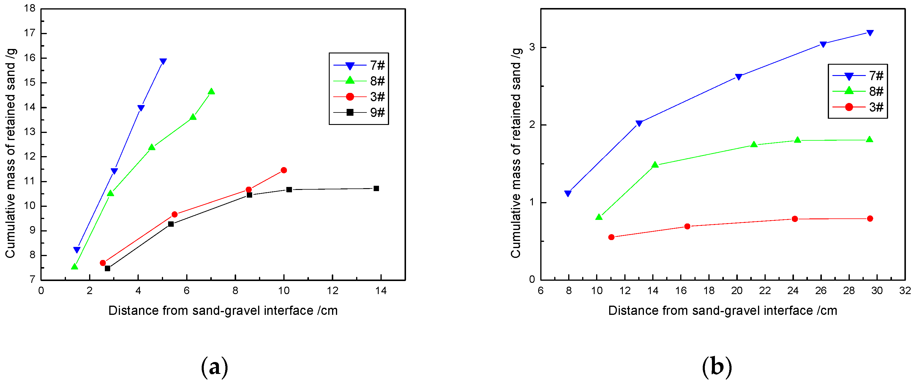
3.3. Two-Stage Gravel Packing Length

The two-stage packing length ratio is a critical factor that influences the sand control effect of the gravel packs. However, because of the limitations of objective factors such as the length of the sand packing tube and the distribution of pressure measuring points, very few conventional gravel packing experiments had the pack length ratio taken into account. In this experiment, because the packing quantity of the two-stage gravel could be controlled, the influence of packing length was investigated in this study.
It can be observed from Figure 9 that the sand pore filling phenomenon only existed in gravel bed I, while sedimentation occurred when particles intruded into the gravel bed II layer instead of pore filling. For all four groups, in the first 60 min, the intrusive sand was filled in the pore space of gravel bed I with the same expansion regularity. From 60 to 180 min, the pore filling depth of group 7# exceeded 5 cm, which was the packing length of gravel bed I. The sand fell into gravel bed II, and this resulted in sand sedimentation on the pipe wall and a large amount of retained sand at the two-stage interface. The pore filling front of groups 8# and 3# broke through gravel bed I around 120 min. Sand settlement took place at the two-stage gravel interface as well. However, the amount of retained sand was quite a bit smaller than group 7#. Intrusive sand in group 9# migrated within gravel bed I all through the displacement process, and no visible penetration front formed.
From Figure 10, it can be seen that the pore filling of the intrusion sand was only formed in gravel bed I. After the pore filling of gravel bed I was completed in group 7# with a packing length of 5 cm, the pore filling front had not been extended to gravel bed II. Sand particles only migrated in gravel bed I of group 9#, thus the pore filling depth of group 9# with a packing length of 15 cm was only slightly less than 7 cm and 10 cm. However, since gravel bed I had a lower porosity, particle penetration depth was apparently less than that of the other two groups, with a value of 10 cm. Because the stability value of pore filling depth under the experimental setting was more than 7 cm but less than 10 cm, the sand intrusion depth of group 3# was significantly reduced compared with that of group 8#.
As shown in Figure 11, in group 9#, intrusive sand was only distributed in gravel bed I, while in the first 10 cm or so of gravel bed I, the degree of blockage was similar to that of group (c), but no sand intrusion occurred after 10 cm. In the other three groups of experiments, the retained sand was all distributed along the whole of the two-stage gravel packs. The masses of retained particles in gravel bed I of groups 7# and 8# were 16 g and 15 g, respectively, which were significantly higher than 11.5 g and 10.4 g in groups 3# and 9#. A large amount of sand migrated into gravel bed II in group 7# and intruded to the end front of the gravel pack, consequently forming sand-production. Retained sand in gravel bed II of group 3# was about 0.5 g and was mainly concentrated at the two-stage interface, while the sand blockage in the middle of gravel bed II was less serious compared to that of group 8#, which had 1.6 g of sand retention.
Through the above experiments, the following conclusions can be drawn: after the completion of pore filling in gravel bed I of groups (a) and (b) with packing lengths of 5 cm and 7 cm, no pore filling phenomenon occurred in gravel bed II, however, a large amount of sand settlement formed at the two-stage interface. Under the experimental conditions, the pore filling front of group (c) would not break through gravel bed I, and the majority of intrusive sand settled at the two-stage interface instead of further penetration. It is suggested that the packing depth of gravel bed I should be 10 cm in this case.

4. Conclusions

In this study, particle migration and blockage in a two-stage gravel pack were obtained by conducting our newly designed visualization experiment. The effect of the two-stage gravel size and the packing ratio on pore filling length and particle penetration depth was analyzed. Also, the particle retained in each gravel pack section was analyzed. By obtaining the stable value of pore filling depth and pore plugging degree, the basis for gradation and grain size selection in sand control operations of two-stage gravel packing was proposed. Our work can provide guidance for designing a two-stage gravel pack during the development of unconventional reservoirs with high sand production rates and fine silt content. The following conclusions can be drawn from this work:
(1)
The pore filling depth could be shorter in the cases where grain ratio of gravel bed I to sand was less than five. The reason is that the sand bridge formed in the pore space of the gravel pack could restrain further particle penetration.
(2)
The grain size of gravel bed II had little influence on the length of the pore filling zone and the amount of retained particles in gravel beds I and II. It mainly affected the amount of retained sand at the two-stage interface and the particle penetration depth.
(3)
After completion of pore filling in gravel bed I in cases with packing lengths of 5 cm and 7 cm, no pore filling phenomenon occurred in gravel bed II. However, a large amount of sand settlement formed at the two-stage interface.

Author Contributions

Conceptualization, X.M.; Methodology, X.M., M.Q. and Z.M.; Formal analysis, Z.M. and T.L.; Investigation, X.M., Z.M. and M.Q.; Writing—original draft preparation, X.M.; Writing—review and editing, T.L., Z.N., and M.Q.; Funding Acquisition, X.M.

Funding

This research was funded by Shandong Natural Science Foundation Funded Project (Grant ZR2018BEE011), Fundamental Research Funds for the Central Universities National Science (Grant No. 18CX02027A), and Technology Major Project of the Ministry of Science and Technology of China (Grant No. 2016ZX05011004-003).

Acknowledgments

The Sand Control Lab in China University of Petroleum (East China) is highly appreciated.

Conflicts of Interest

The authors declare no conflict of interest.

References

  1. Chen, Y.; Deng, J.; Zhao, W. Research on solutions of the influences of high pressure repeating packing sand control on productivity. Pet. Sci. Technol. 2013, 31, 88–93. [Google Scholar] [CrossRef]
  2. Deng, F.; Feng, Y.; Yan, C.; Lin, H.; Gong, N.; Wang, J. Experimental investigation of factors affecting gravel pack efficiency for thermal recovery wells in Bohai Bay, China. J. Pet. Sci. Eng. 2017, 156, 835–844. [Google Scholar] [CrossRef]
  3. Mirshekari, B.; Dadvar, M.; Modares, H.; Dabir, B. Modelling and simulation of gravel-pack damage due to particle transport by single phase flow in cased hole completion. Int. J. Oil Gas Coal Technol. 2014, 7, 152–168. [Google Scholar] [CrossRef]
  4. Sparlin, D.D. Sand and Gravel—A Study of Their Permeabilities. In Proceedings of the SPE Symposium on Formation Damage Control, New Orleans, LA, USA, 30 January–2 February 1974. [Google Scholar] [CrossRef]
  5. Li, Y.; Liu, L.; Sun, J.; Ye, Y.; Chen, Q. Sanding prediction and sand-control technology in hydrate exploitation: A review and discussion. Mar. Geol. Front. 2016, 32, 36–43. [Google Scholar]
  6. Deng, J.; Tan, Q.; Sun, Y.; Chen, Y.; Duan, Z.; Wei, L.; Wang, E. Influence of high pressure pack repeat sand control on productivity and solution. Fault Block Oil Gas Field 2010, 17, 494–496. [Google Scholar]
  7. Chen, Y.; Deng, J.; Zhao, W. Research of gravel size optimization in sand control with variable particle diameter packing. J. Oil Gas Technol. 2010, 6, 319–321. [Google Scholar]
  8. Bouhroum, A.; Civan, F. A Study of particulates migration in gravel pack. In Proceedings of the SPE Formation Damage Control Symposium, Lafayette, LA, USA, 7–10 February 1994. [Google Scholar]
  9. Bigno, Y.; Oyeneyin, M.B.; Peden, J.M. Investigation of pore-blocking mechanism in gravel packs in the management and control of fines migration. In Proceedings of the SPE Formation Damage Control Symposium, Lafayette, LA, USA, 7–10 February 1994. [Google Scholar]
  10. Ali, M.A.J.; Currie, P.K.; Salman, M.J. Measurement of the particle deposition profile in deep-bed filtration during produced water re-injection. In Proceedings of the SPE Middle East Oil and Gas Show and Conference, Manama, Kingdom of Bahrain, 12–15 March 2015. [Google Scholar]
  11. Shirinabadi, R.; Moarefvaand, P.; Goshtasbi, K.; Ahangari, K. The physical and numerical modeling of sand production and gravel pack in oil wells by designing and manufacturing the machine and presenting a relation estimating sand production rate. J. Min. Sci. 2016, 52, 300–312. [Google Scholar] [CrossRef]
  12. Villarroel, F.M.G.; Vargas, E.A.J.; Bloch, M. Experimental analysis of gravel pack mesh size effect on the screen deformation under high in situ stress contrast. J. Am. Chem. Soc. 2010, 95, 4634–4639. [Google Scholar]
  13. Lawal, K.A.; Vesovic, V.; Boek, E.S. Modeling permeability impairment in porous media due to asphaltene deposition under dynamic conditions. Energy Fuels 2011, 25, 5647–5659. [Google Scholar] [CrossRef]
  14. Gravelle, A.; Peysson, Y.; Tabary, R.; Egermann, P. Controlled release of colloidal particles and remediation: Experimental investigation and modelling. In Proceedings of the SPE International Symposium on Oilfield Chemistry, The Woodlands, TX, USA, 11–13 April 2011. [Google Scholar]
  15. Li, Y.; Li, M.; Wang, L.; Meng, W. A Productivity Prediction Model for the Gravel-packed Horizontal Well. Liq. Fuels Technol. 2013, 31, 633–642. [Google Scholar] [CrossRef]
  16. Li, Y.; Qin, G.; Li, M.; Wang, W. Numerical simulation study on gravel-packing layer damage by integration of innovative experimental observations. In Proceedings of the SPE Heavy Oil Conference Canada, Calgary, AB, Canada, 12–14 June 2012. [Google Scholar]
  17. Civan, F. Reservoir formation damage: Fundamentals, modeling, assessment, and mitigation. Herd Health Environ. Res. Des. J. 2000, 7, 60–77. [Google Scholar]
  18. Keller, A.A.; Auset, M. A review of visualization techniques of biocolloid transport processes at the pore scale under saturated and unsaturated conditions. Adv. Water Resour. 2007, 30, 1392–1407. [Google Scholar] [CrossRef]
  19. Jacobsen, O.H.; Moldrup, P.; Larsen, C.; Petersen, L.W. Particle transport in macropores of undisturbed soil columns. J. Hydrol. 1997, 196, 185–203. [Google Scholar] [CrossRef]
  20. Benamar, A.; Ahfir, N.D.; Wang, H.Q.; Alem, A. Particle transport in a saturated porous medium: Pore structure effects. Comptes Rendus Géosci. 2007, 339, 674–681. [Google Scholar] [CrossRef]
  21. Moghadasi, J.; Müller-Steinhagen, H.; Jamialahmadi, M.; Sharif, A. Theoretical and experimental study of particle movement and deposition in porous media during water injection. J. Pet. Sci. Eng. 2004, 43, 163–181. [Google Scholar] [CrossRef]
  22. Rolle, M.; Hochstetler, D.; Chiogna, G.; Kitanidis, P.K.; Grathwohl, P. Experimental Investigation and Pore-Scale Modeling Interpretation of Compound-Specific Transverse Dispersion in Porous Media. Transp. Porous Media 2012, 93, 347–362. [Google Scholar] [CrossRef]
  23. Parker, S.E.; Lee, W.W. A fully nonlinear characteristic method for gyrokinetic simulation. Phys. Fluids B Plasma Phys. 1993, 5, 77–86. [Google Scholar] [CrossRef] [Green Version]
  24. Shin, C. Numerical simulation for particle penetration depth distribution in deep bed filtration. Chem. Eng. Technol. 2006, 29, 905–909. [Google Scholar] [CrossRef]
  25. Ma, S.; Dong, M.; Li, Z.; Shirif, E. Evaluation of the effectiveness of chemical flooding using heterogeneous sandpack flood test. J. Pet. Sci. Eng. 2007, 55, 294–300. [Google Scholar] [CrossRef]
  26. Liu, Q.; Cui, X.; Zhang, C.; Huang, S. Experimental investigation of suspended particles transport through porous media: Particle and grain size effect. Environ. Technol. Lett. 2016, 37, 11. [Google Scholar] [CrossRef]
  27. Bedrikovetsky, P.; Marchesin, D.; Shecaira, F.; Souza, A.L.; Milanez, P.V.; Rezende, E. Characterisation of deep bed filtration system from laboratory pressure drop measurements. J. Pet. Sci. Eng. 2001, 32, 167–177. [Google Scholar] [CrossRef]
  28. Bedrikovetsky, P. Upscaling of stochastic micro model for suspension transport in porous media. Transp. Porous Media 2008, 75, 335–369. [Google Scholar] [CrossRef]
  29. Kim, Y.S.; Whittle, A.J. Filtration in a porous granular medium: 1. simulation of pore-scale particle deposition and clogging. Transp. Porous Media 2006, 65, 53–87. [Google Scholar] [CrossRef]
  30. Guedes, R.G.; Al-Abduwani, F.A.H.; Bedrikovetsky, P.; Currie, P.K. Deep-bed filtration under multiple particle-capture mechanisms. SPE J. 2009, 14, 477–487. [Google Scholar] [CrossRef]
  31. Araújo, J.A.; Santos, A. Analytic model for DBF under multiple particle retention mechanisms. Transp. Porous Media 2013, 97, 135–145. [Google Scholar] [CrossRef]
  32. Kuhnen, F.; Barmettler, K.; Bhattacharjee, S.; Elimelech, M.; Kretzschmar, R. Transport of iron oxide colloids in packed quartz sand media: Monolayer and multilayer deposition. J. Colloid Interface Sci. 2000, 231, 32–41. [Google Scholar] [CrossRef]
  33. Carlson, D.R.; Widnall, S.E.; Peeters, M.F. A flow-visualization study of transition in plane Poiseuille flow. J. Fluid Mech. 1982, 121, 487–505. [Google Scholar] [CrossRef]
  34. Zamani, A.; Maini, B. Flow of dispersed particles through porous media—Deep bed filtration. J. Pet. Sci. Eng. 2009, 69, 71–88. [Google Scholar] [CrossRef]
  35. Saucier, R.J. Considerations in gravel pack design. J. Pet. Technol. 1974, 26, 205–212. [Google Scholar] [CrossRef]
Figure 1. Diagram of two-stage gravel packing well.
Energies 12 01519 g001
Figure 2. The flowchart and set-up of the experimental device.
Energies 12 01519 g002
Figure 3. Sand distribution in gravel packs affected by grain size of gravel bed I.
Energies 12 01519 g003
Figure 4. The dynamic diversification chart of the pore filling and the particle penetration depth influenced by grain size of gravel bed I: (a) pore filling depth; (b) particle penetration depth.
Energies 12 01519 g004
Figure 5. The cumulative mass of retained sand in two-stage gravel beds influenced by grain size of gravel bed I: (a) gravel bed I (b) gravel bed II.
Energies 12 01519 g005
Figure 6. Sand distribution in gravel packs affected by grain size of gravel bed II.
Energies 12 01519 g006
Figure 7. The dynamic diversification chart of the pore filling and particle penetration depth influenced by grain size of gravel bed II: (a) pore filling depth (b) particle penetration depth.
Energies 12 01519 g007
Figure 8. The cumulative mass of retained sand in two-stage gravel beds influenced by grain size of gravel bed II: (a) gravel bed I (b) gravel bed II.
Energies 12 01519 g008
Figure 9. Sand distribution in gravel packs affected by two-stage packing length.
Energies 12 01519 g009
Figure 10. The dynamic diversification chart of the pore filling and particle penetration depth influenced by two-stage packing length: (a) pore filling depth; (b) particle penetration depth.
Energies 12 01519 g010
Figure 11. The cumulative mass of retained sand in two-stage gravel beds influenced by two-stage packing length: (a) gravel bed I (b) gravel bed II.
Energies 12 01519 g011
Table 1. Experimental scheme.
Group NumberSand Median Grain size (mm)Gravel Bed I Grain Size (mm)Gravel Bed II Grain Size (mm)Displacement Rate (mL/min)Packing Length (I)/cmPacking Length (II)/cm
1#0.853.572001020
2#0.85472001020
3#0.854.572001020
4#0.85572001020
5#0.854.562001020
6#0.854.582001020
7#0.854.57200525
8#0.854.57200723
9#0.854.572001515

